EP2637262A1 - Connector, connector assembly and assembling/disassembling method therefor - Google Patents
Connector, connector assembly and assembling/disassembling method therefor Download PDFInfo
- Publication number
- EP2637262A1 EP2637262A1 EP13000684.4A EP13000684A EP2637262A1 EP 2637262 A1 EP2637262 A1 EP 2637262A1 EP 13000684 A EP13000684 A EP 13000684A EP 2637262 A1 EP2637262 A1 EP 2637262A1
- Authority
- EP
- European Patent Office
- Prior art keywords
- main body
- housing main
- housing
- detecting member
- lock arm
- Prior art date
- Legal status (The legal status is an assumption and is not a legal conclusion. Google has not performed a legal analysis and makes no representation as to the accuracy of the status listed.)
- Withdrawn
Links
Images








Classifications
-
- H—ELECTRICITY
- H01—ELECTRIC ELEMENTS
- H01R—ELECTRICALLY-CONDUCTIVE CONNECTIONS; STRUCTURAL ASSOCIATIONS OF A PLURALITY OF MUTUALLY-INSULATED ELECTRICAL CONNECTING ELEMENTS; COUPLING DEVICES; CURRENT COLLECTORS
- H01R13/00—Details of coupling devices of the kinds covered by groups H01R12/70 or H01R24/00 - H01R33/00
- H01R13/62—Means for facilitating engagement or disengagement of coupling parts or for holding them in engagement
- H01R13/627—Snap or like fastening
-
- H—ELECTRICITY
- H01—ELECTRIC ELEMENTS
- H01R—ELECTRICALLY-CONDUCTIVE CONNECTIONS; STRUCTURAL ASSOCIATIONS OF A PLURALITY OF MUTUALLY-INSULATED ELECTRICAL CONNECTING ELEMENTS; COUPLING DEVICES; CURRENT COLLECTORS
- H01R13/00—Details of coupling devices of the kinds covered by groups H01R12/70 or H01R24/00 - H01R33/00
- H01R13/62—Means for facilitating engagement or disengagement of coupling parts or for holding them in engagement
- H01R13/627—Snap or like fastening
- H01R13/6271—Latching means integral with the housing
- H01R13/6272—Latching means integral with the housing comprising a single latching arm
-
- H—ELECTRICITY
- H01—ELECTRIC ELEMENTS
- H01R—ELECTRICALLY-CONDUCTIVE CONNECTIONS; STRUCTURAL ASSOCIATIONS OF A PLURALITY OF MUTUALLY-INSULATED ELECTRICAL CONNECTING ELEMENTS; COUPLING DEVICES; CURRENT COLLECTORS
- H01R13/00—Details of coupling devices of the kinds covered by groups H01R12/70 or H01R24/00 - H01R33/00
- H01R13/64—Means for preventing incorrect coupling
- H01R13/641—Means for preventing incorrect coupling by indicating incorrect coupling; by indicating correct or full engagement
-
- H—ELECTRICITY
- H01—ELECTRIC ELEMENTS
- H01R—ELECTRICALLY-CONDUCTIVE CONNECTIONS; STRUCTURAL ASSOCIATIONS OF A PLURALITY OF MUTUALLY-INSULATED ELECTRICAL CONNECTING ELEMENTS; COUPLING DEVICES; CURRENT COLLECTORS
- H01R43/00—Apparatus or processes specially adapted for manufacturing, assembling, maintaining, or repairing of line connectors or current collectors or for joining electric conductors
- H01R43/26—Apparatus or processes specially adapted for manufacturing, assembling, maintaining, or repairing of line connectors or current collectors or for joining electric conductors for engaging or disengaging the two parts of a coupling device
Definitions
- the present invention relates to a connector, to a connector assembly and to an assembling or disassembling method therefor.
- a connector disclosed in Japanese Unexamined Patent Publication No. 2004-103551 includes a mating housing with a lock receiving portion, a housing main body connectable to the mating housing, a lock arm extending backward in a cantilever manner from a front end part of the housing main body and configured to hold the housing main body and the mating housing in a connected state by being resiliently engaged with the lock receiving portion, and a detecting member to be mounted on the housing main body movably from an initial position to a detection position and configured to detect whether or not the mating housing has been properly connected to the housing main body based on whether or not the detecting member can be moved to the detection position.
- a disengaging portion to be pressed in releasing an engaged state with the lock receiving portion is formed on a rear end part of the lock arm.
- the connector includes a protection wall standing up from the housing main body and covering the upper surface of the disengaging portion, thereby preventing the disengaging portion from being turned up.
- the detecting member includes a rear portion located behind the lock arm and to be pressed when the detecting member is moved to the detection position.
- the rear portion is in the form of a flat plate covering a rear part of the disengaging portion.
- the engaged state of the lock arm and the lock receiving portion has to be released by placing fingers or a jig on a side of the disengaging portion facing the protection wall from above and, in that state, pressing down the disengaging portion.
- a space for permitting the entrance of fingers or the jig at the protection wall side becomes smaller as the connector becomes smaller, there is a problem that it is difficult to operate the disengaging portion.
- the present invention was completed in view of the above situation and an object thereof is to facilitate an operation of releasing an engaged state of a lock arm.
- a connector comprising: a housing main body to be connected to a mating housing; a lock arm projecting from the housing main body, resiliently deformable in a deforming direction intersecting with a connecting direction of the housing main body with the mating housing, forming a deformation space between the lock arm and the housing main body, configured to hold the housing main body connected to the mating housing in a connected state by being resiliently engaged with a lock receiving portion of the mating housing, and including a disengaging portion to be operated in releasing an engaged state with the lock receiving portion; at least one protection wall projecting from the housing main body and configured to restrict an operation of the disengaging portion by at least partly covering a surface of the disengaging portion at a side substantially opposite to a surface facing the deformation space; and a detecting member to be mounted on or to the housing main body movably from an initial position to a detection position, configured such that a movement in a displacement direction is restricted at the initial position before the housing main body is
- the surface of the disengaging portion substantially opposite to the one facing the deformation space is at least partly covered by the protection wall and an inadvertent operation of the disengaging portion is prevented by the protection wall, whereas fingers or the jig are/is placed on the disengaging portion through the disengagement window formed on the rear portion of the detecting member to operate the disengaging portion in releasing the engaged state of the lock arm. Therefore, according to the above, an operation of releasing the engaged state of the lock arm can be easily performed, thereby improving overall operability.
- the lock arm extends backward in a cantilever manner from a front end part of the housing main body.
- the disengaging portion is formed on a rear end part of the lock arm.
- the adjacent portion is a rear portion which is located behind the lock arm and wherein the disengagement window is formed on a position of the rear portion substantially behind the disengaging portion.
- the adjacent portion is formed with a pair of catching portions located at substantially opposite sides of the disengagement window.
- the one or more catching portions are catchable by fingers or a jig in moving the detecting member in a return direction opposite to the displacement direction to the detection position.
- the disengagement window is a recess having a substantially angular U-shaped cross section and/or formed in a widthwise intermediate part of the adjacent portion.
- the disengaging portion of the lock arm can be at least partly seen through the disengagement window when the detecting member mounted on the housing main body is viewed from a mounting side.
- the detecting member is configured such that (i) the insertion movement is restricted at the initial position by the contact of a resilient arm portion of the detecting member with the lock arm before the housing main body is connected to the mating housing; (ii) the movement restricted state at the initial position is released and the detecting member is capable of reaching the detection position where the resilient arm portion at least partly enters the deformation space by being displaced from the initial position when the housing main body is properly connected to the mating housing; and/or (iii) the resilient arm portion is held in contact with the lock arm in the deforming direction at the initial position to apply a pre-load to the lock arm.
- the lock arm includes an accommodating recess which is open toward the deformation space and/or toward the back, and wherein the detecting member is configured such that: (i) a movement in a movement direction is restricted at the initial position by the contact thereof with the lock arm along the movement direction before the housing main body is connected to the mating housing; (ii) a movement restricted state at the initial position is released and the detecting member is kept at the standby position to substantially face the accommodating recess along the movement direction when the housing main body is properly connected to the mating housing; and (iii) the detecting member reaches the detection position by a displacement operation in the movement direction from the standby position, whereby at least one part of the detecting member is inserted into the accommodating recess.
- a connector assembly comprising: a connector according to the above aspect of the invention or a particular embodiment thereof, having a housing; and a mating connector having a mating housing connectable with the housing, the mating housing having a lock receiving portion engageable with the lock arm to lock the housings in the connected state.
- a connector assembly comprising a mating housing including a lock receiving portion; a housing main body connectable to the mating housing; a lock arm extending backward in a cantilever manner from a front end part of the housing main body, resiliently deformable in a height direction intersecting with a connecting direction of the housing main body and the mating housing, forming a deformation space between the lock arm and the housing main body, configured to hold the housing main body and the mating housing in a connected state by being resiliently engaged with the lock receiving portion, and including a disengaging portion on a rear end part to be pressed in releasing an engaged state with the lock receiving portion; a protection wall standing up from a rear end part of the housing main body and configured to restrict an operation of the disengaging portion by covering a surface of the disengaging portion at a side opposite to a surface facing the deformation space; and a detecting member to be mounted on the housing main body movably from an initial position to a
- the surface of the disengaging portion opposite to the one facing the deformation space is covered by the protection wall and an inadvertent operation of the disengaging portion is prevented by the protection wall, whereas fingers or the jig are/is placed on the disengaging portion through the disengagement window formed on the rear portion of the detecting member to operate the disengaging portion in releasing the engaged state of the lock arm. Therefore, according to the above, an operation of releasing the engaged state of the lock arm can be easily performed.
- the rear portion is formed with a pair of catching portions located at opposite sides of the disengagement window and catchable by fingers or a jig in moving the detecting member in a return direction opposite to a moving direction to the detection position.
- the catching portions on the rear portion are caught by fingers or the jig and the detecting member is pulled back to the initial position. Thereafter, the disengaging portion can be operated. Since the pair of catching portions are arranged at the opposite sides of the disengagement window in this case, space efficiency of the rear portion is improved and the miniaturization of the connector can be met.
- a method of assembling a connector assembly comprising the following steps: (i) providing a connector having a housing main body and a lock arm projecting from the housing main body and being resiliently deformable in a deforming direction intersecting with a connecting direction of the housing main body with the mating housing, forming a deformation space between the lock arm and the housing main body; (ii) providing a mating connector having a mating housing; (iii) matingly connecting the housing main body with the mating housing thereby resiliently engaging the lock arm with a lock receiving portion of the mating housing to hold the housing main body and the mating housing in a connected state, wherein the lock arm includes a disengaging portion to be operated in releasing an engaged state with the lock receiving portion, and wherein at least one protection wall projects from the housing main body and is configured to restrict an operation of the disengaging portion by at least partly covering a surface of the diseng
- a method of assembling a connector assembly comprising: (i) providing an assembled connector assembly of a connector and a mating connector, wherein the connector comprises a housing main body and a lock arm projecting from the housing main body and being resiliently deformable in a deforming direction intersecting with a connecting direction of the housing main body with the mating housing, forming a deformation space between the lock arm and the housing main body; and wherein the a mating connector comprises a mating housing matingly connected with the housing main body whereby the lock arm of the housing main body is resiliently engaged with a lock receiving portion of the mating housing to hold the housing main body and the mating housing in a connected state; and wherein a detecting member is mounted on or to the housing main body movably from an initial position to a detection position and includes an adjacent portion located adjacent the lock arm and to be operated when the detecting member is moved to the detection position, (ii
- the detecting member is configured such that a movement in a displacement direction is restricted at the initial position before the housing main body is connected to the mating housing and a movement restricted state at the initial position is released and the detecting member is capable of reaching the detection position by being displaced in the displacement direction when the housing main body is properly connected to the mating housing.
- the lock arm extends backward in a cantilever manner from a front end part of the housing main body, and/or wherein the disengaging portion is formed on a rear end part of the lock arm, and/or wherein the adjacent portion is a rear portion which is located behind the lock arm and wherein the disengagement window is formed on a position of the rear portion substantially behind the disengaging portion, and/or wherein the adjacent portion is formed with a pair of catching portions located at substantially opposite sides of the disengagement window, and/or wherein the one or more catching portions are catchable by fingers or a jig in moving the detecting member in a return direction opposite to the displacement direction to the detection position.
- a connector according to this embodiment includes a housing 10 and a mating housing 50 connectable to each other, and a detecting member 70 to be mounted on or in the housing 10. Note that, in the following description, sides of the two housings 10, 50 to be connected are referred to as front sides concerning forward and backward directions FBD.
- the mating housing 50 is made e.g. of synthetic resin and includes a (particularly substantially tubular) receptacle 51 which is open forward as shown in FIG. 11 .
- a lock receiving portion 52 is formed in or on (particularly a front end part of the outer or upper wall of) the receptacle 51.
- the lock receiving portion 52 particularly penetrates through the receptacle 51 (particularly the upper wall) in a height direction HD (direction intersecting with a connecting direction CD of the two housings 10, 50).
- the inner front surface of the lock receiving portion 52 serves as an engaging surface 53 which is a reverse tapered surface inclined slightly forward toward an upper or outer side.
- an interfering portion 54 is formed at a position adjacent (particularly immediately before) the lock receiving portion 52 at the (particularly front end part of the outer or upper wall of) the receptacle 51.
- An inclined surface 55 which is a tapered surface inclined forward toward an upper or outer side is formed at (particularly a lower or inner end part of the front surface of) the interfering portion 54.
- the lower or inner surface of the interfering portion 54 is arranged substantially horizontally (parallel to the connecting direction CD) from the inclined surface 55 to the lock receiving portion 52 and serves as a pressing surface 56 capable of pressing a protrusion 87 of the detecting member 70 (to be described later) and a lock projection 24 of a lock arm 12 from above or outside.
- the housing 10 is made e.g. of synthetic resin and includes a (particularly substantially block-shaped) housing main body 11 and a resiliently deformable and (particularly substantially cantilever-shaped) lock arm 12 integrally or unitarily coupled to (particularly the upper surface of) the housing main body 11 as shown in FIGS. 3 and 4 .
- One or more unillustrated terminal fittings are at least partly insertable into the housing main body 11.
- a (particularly substantially arch-shaped or bent or gate-shaped) protection wall 13 at least partly surrounding a rear end part (disengaging portion 28 to be described later) of the lock arm 12 is formed on the upper or outer surface of (particularly a rear end part of) the housing main body 11 as shown in FIGS. 5 and 6 .
- the protection wall 13 particularly is composed of or comprises a pair of outer side walls 14 standing up or projecting from substantially opposite widthwise end parts of the upper surface of the housing main body 11, a pair of inner side walls 15 located at inner sides of the both outer side walls 14 and standing up or projecting from the upper surface of the housing main body 11, and a covering wall 16 connected to (particularly the upper or distal ends of) the both inner side walls 15 and/or the both outer side walls 14 and particularly substantially extending over the entire width of the housing main body 11.
- an inner space of the protection wall 13 serves as a mount space 17 into which the detecting member 70 is to be at least partly inserted in an insertion direction ID (particularly parallel to the connecting direction CD), particularly substantially from behind.
- the covering wall 16 particularly is formed with at least one cut portion 18 which is open on-the rear end of the covering wall 16.
- the disengaging portion 28 of the lock arm 12 particularly can be at least partly seen through the cut portion(s) 18.
- the rear ends of the inner side walls 15 particularly are located before the rear ends of the outer side walls 14 by being at least partly partitioned by the cut portion 18.
- one or more, particularly a pair of guide grooves 19 are formed on (particularly the inner surface(s) of lower end part(s) of) the (particularly both) outer side wall(s) 14.
- the (both) guide groove(s) 19 particularly has/have a rectangular cross section, substantially extend in forward and backward directions FBD and/or is/are open on both front and rear ends of the (both) outer side wall(s) 14.
- One or more, particularly a pair of first retaining portions 21 are formed to project inward on the inner surfaces of (particularly lower parts of the rear ends of) the (particularly both) guide groove(s) 19. As shown in FIG.
- the rear surface(s) of the first retaining portion(s) 21 particularly is/are tapered surface(s) inclined inwardly toward the front and the front surface(s) thereof extend substantially in a width direction WD (a direction at an angle different from 0° or 180°, preferably substantially perpendicular to the forward and backward directions FBD and/or the inserting direction ID and/or the connecting direction CD).
- One or more, particularly a pair of second retaining portions 22 are formed to project outward on the outer surface(s) of (particularly rear end part(s) of) the (particularly both) inner side wall(s) 15.
- the (both) second retaining portion(s) 22 particularly substantially is/are in the form of long and narrow ribs substantially extending upward or outward (particularly in a height direction HD or a direction at an angle different from 0° or 180°, preferably substantially perpendicular to the forward and backward directions FBD and/or the inserting direction ID and/or the connecting direction CD and/or the width direction WD) from the outer or upper surface of the housing main body 11.
- the rear surface(s) of the second retaining portion(s) 22 particularly is/are tapered surface(s) inclined outwardly toward the front and/or the front surface(s) thereof particularly is/are reverse tapered surface(s) inclined slightly forwardly toward an outer side.
- one or more, particularly a pair of restricting portions 23 are formed to project outward on (particularly the outer surface(s) of front end part(s) of) the (particularly both) inner side wall(s) 15.
- the (both) restricting portion(s) 23 particularly is/are in the form of long and narrow ribs substantially extending downward or inward in the height direction HD from the lower or inner surface of the covering wall 16.
- the restricting portion(s) 23 particularly has/have a shorter projecting distance than the second retaining portion(s) 22 and/or a longer extending length than the second retaining portion(s) 22 and/or particularly is/are substantially arranged above or corresponding to the second retaining portion(s) 22.
- the rear surface(s) of the restricting portion(s) 23 particularly is/are tapered surface(s) inclined outwardly toward the front and/or the front surface(s) thereof is/are tapered surface(s) inclined inwardly toward the front.
- the lock arm 12 substantially extends backward or along the connecting direction CD from (particularly the upper or outer surface of a front end part of) the housing main body 11.
- the lock projection 24 is formed to project in the height direction HD in an intermediate part (particularly in a substantially central part) of the lock arm 12 in forward and backward directions FBD.
- a deformation space 25 is formed between the lower or inner surface of the lock arm 12 and the upper or outer surface of the housing main body 11.
- the lock arm 12 particularly includes a base end portion 26 (particularly substantially in the form of a rectangular plate) before the lock projection 24.
- a front end side of the base end portion 26 is coupled to the upper surface of the housing main body 11 and serves as a supporting point of resilient deformation of the lock arm 12.
- the lock arm 12 includes one or more, particularly a pair of coupling portions 27 substantially extending backward from (particularly both sides of) the lock projection 24 and the disengaging portion 28 coupled to the rear end(s) of the (both) coupling portion(s) 27, substantially extending in the width direction WD and arranged to be slightly higher.
- the rear surface of the lock projection 24 serves as a locking surface 29 substantially facing backward, wherein an upper or outer side facing the engaging surface 53 of the lock receiving portion 52 particularly is slightly reversely tapered and/or a lower or inner side facing a movement restricting surface 94 (to be described later) of the detecting member 70 particularly is slightly tapered as shown in FIG. 11 .
- the lock projection 24 at least partly is resiliently fitted into the lock receiving portion 52 from below or inside and the locking surface 29 is arranged to be able to come into contact with the engaging surface 53, whereby the two housings 10, 50 are held in a connected state CS.
- the lock arm 12 is resiliently deformed to at least partly enter the deformation space 25 by pressing the disengaging portion 28 from above or outside with the two housings 10, 50 properly connected. In this way, the lock projection 24 exits from the lock receiving portion 52 and the two housings 10, 50 can be separated or pulled apart.
- an accommodating recess 31 is so formed on the lower surface of the lock arm 12 to be open backward.
- the accommodating recess 31 is so dimensioned and/or shaped that the protrusion 87 of the detecting member 70 at least partly is fittable thereinto, and is open on the lower or inner surface (facing toward the deformation space 25) of the lock arm 12 and/or the rear surface of the lock projection 24.
- the inner upper surface of the accommodating recess 31 particularly is located higher than the upper surface of the base end portion 26 of the lock arm 12. Further, the inner upper surface of the accommodating recess 31 particularly is partly recessed to form an auxiliary recess 32. As shown in FIG.
- the auxiliary recess 32 is arranged in a widthwise intermediate part (particularly in a widthwise central part) of the inner upper surface of the accommodating recess 31 and has a width which particularly is leass than about half (particularly which is about 1/3) of the entire width of the accommodating recess 31.
- a depth of the auxiliary recess 32 is set to be sufficiently smaller than that of the accommodating recess 31.
- the detecting member 70 is likewise made e.g. of synthetic resin and includes a main portion 71 and a resilient arm portion 72 integrally or unitarily coupled to (particularly the front end of) the main portion 71 as shown in FIGS. 7 and 8 .
- the detecting member 70 is to be mounted on or in the housing main body 11 movably from an initial position IP to a detection position DP via a standby position SP.
- the main portion 71 includes a rear portion 73 substantially extending in the width direction WD and/or the height direction HD.
- the rear portion 73 is formed with a disengagement window 74.
- the disengagement window 74 particularly is a recess having a substantially angular U-shaped cross section and/or formed in a widthwise intermediate part (particularly in a substantially widthwise central part) of the upper end edge of the rear portion 73.
- the rear portion 73 includes one or more, particularly a pair of vertical portions 75 substantially extending in the height direction HD at opposite widthwise end parts and/or a horizontal portion 76 particularly coupled to rear end parts of the both vertical portions 75 and/or substantially extending in the width direction WD.
- the disengagement window 74 is partitioned by the both vertical portions 75 and the horizontal portion 76.
- the rear surfaces of the both vertical portions 75 and the horizontal portion 76 are arranged substantially along the height direction HD and can be pressed or operated (particularly in the inserting direction ID or from behind) during a movement to the detection position DP.
- a pair of catching portions 77 are formed to project on the upper ends of the both vertical portions 75.
- the both catching portions 77 are or can be caught by fingers or a jig and a displacement force (particularly a backward pulling force) acts on the both catching portions 77 in that state, whereby the detecting member 70 is or can be displaced (pulled back) from the detection position DP to the initial position IP.
- the both vertical portions 75 particularly have a substantially rectangular side view and include one or more, particularly a pair of guide portions 78 on (particularly lower end parts of the outer surfaces of) the vertical portions 75.
- the guide portions 78 particularly substantially are in the form of ribs substantially extending in forward and backward directions FBD particularly over the substantially entire length of the horizontal portion 76.
- one or more, particularly a pair of first stopping portions 79 are formed on (particularly a lower part, further particularly on substantially lower halves of) the both guide portions 78.
- the rear surfaces of the first stopping portions 79 substantially extend in the width direction WD.
- Each of the both guide portions 78 includes groove portions 81 located at both front and rear sides of the first stopping portion 79, substantially extending in forward and backward directions FBD and/or open on both front and rear ends.
- first shake preventing portions 82 are formed to project at one or more positions at least partly overlapping with the (particularly both) first stopping portion(s) 79 in forward and backward directions FBD on (particularly the upper surfaces of rear parts of) the (both) guide portions 78.
- the (both) first shake preventing portion(s) 82 particularly is/are in the form of ribs substantially extending in forward and backward directions FBD and/or substantially having a triangular or pointed cross section and/or arranged adjacent to thw widthwise end part(s) of the main portion 71, particularly on lower rear sides of opposite widthwise end parts of the main portion 71.
- one or more, particularly a pair of second shake preventing portions 83 are formed to project on the vertical portion(s) 75, particularly substantially on the upper end surfaces of front parts of the both vertical portions 75.
- the second shake preventing portions 83 particularly are in the form of ribs substantially extending in forward and backward directions FBD and/or substantially having a triangular or pointed cross section and/or particularly have a size slightly smaller than the first shake preventing portion(s) 82.
- the (particularly both) second shake preventing portion(s) 83 is/are arranged adjacent to the widthwise end part(s) of the main portion 71, particularly on upper front sides of the opposite widthwise end parts of the main portion 71.
- the (both) first shake preventing portion(s) 82 is/are held in sliding contact with the inner upper surfaces of the (both) guide groove(s) 19 while being squeezed and/or the (both) second shake preventing portion(s) 83 is/are held in sliding contact with the lower surface of the covering wall 16 while being squeezed, whereby a moving posture of the detecting member 70 particularly substantially is corrected to a proper posture.
- one or more, particularly a pair of resilient pieces 84 are formed to substantially project forward on (particularly the front ends of) the (both) vertical portion(s) 75.
- the (both) resilient piece(s) 84 particularly is/are in the form of plate(s) having a substantially rectangular side view and/or resiliently deformable substantially in the width direction WD with the front end(s) of the vertical portion(s) 75 as supporting point(s).
- one or more, particularly a pair of partial locking portions 85 and one or more, particularly a pair of second stopping portions 86 are formed substantially side by side in the height direction HD on (particularly front end parts of) the (both) resilient piece(s) 84.
- the partial locking portion(s) 85 project(s) inward from (particularly substantially upper halves of front end parts of) the resilient piece(s) 84 and substantially extend(s) in the height direction HD.
- the rear surface(s) of the partial locking portion(s) 85 particularly is/are tapered surface(s) inclined inwardly toward the front, and/or the front surface(s) thereof is/are tapered surface(s) inclined outwardly toward the front. As shown in FIG.
- the second stopping portion(s) 86 project(s) inward from (particularly substantially lower halves of front end parts of) the resilient piece(s) 84 and/or substantially extend in the height direction HD.
- the second stopping portion(s) 86 particularly is/are slightly smaller than the partial locking portion(s) 85.
- the rear surface(s) of the second stopping portion(s) 86 particularly is/are reverse tapered surface(s) inclined slightly backwardly toward an inner side. As shown in FIG.
- the rear surface(s) of the first stopping portion(s) 79 particularly is/are held in contact with the first retaining portion(s) 21 from front and/or the rear surface(s) of the second stopping portion(s) 86 particularly is/are held in contact with the second retaining portion(s) 22 from front, thereby preventing the detecting member 70 from being detached from or displaced within the housing main body 11.
- the resilient arm portion 72 particularly substantially extends forward in a cantilever manner from a widthwise intermediate part (particularly a substantially widthwise central part of the front end) of the main portion 71.
- the resilient arm portion 72 particularly is substantially in the form of a rectangular bar and/or resiliently deformable in a deforming direction DD (e.g. the height direction HD or inner and outer directions) particularly with a rear end part connected to the front end of the main portion 71 as a supporting point.
- DD deforming direction
- the resilient arm portion 72 particularly is inclined upwardly or outwardly at a substantially constant angle of inclination from the rear end to the front end of the resilient arm portion 72.
- the resilient arm portion 72 is resiliently deformed along the deforming direction DD to gradually make its angle of inclination smaller as the detecting member 70 is displaced from the initial position IP to the standby position SP. Then, as shown in FIG. 15 , the resilient arm portion 72 particularly is substantially in a horizontal posture without being substantially inclined when the detecting member 70 reaches the detection position DP. Thus, the resilient arm portion 72 particularly is in a state to accumulate a resilient force at the standby position SP and the detection position DP.
- the protrusion 87 (particularly substantially in the form of a rectangular block) is formed to project upward or outward on or near a front or distal end part of the resilient arm portion 72.
- a tapered guide surface 88 inclined upwardly or outwardly toward the back is formed on an upper or outer end part of the front surface of the protrusion 87.
- the guide surface 88 of the protrusion 87 particularly is arranged to substantially face an upper or outer end opening edge of the accommodating recess 31 on the rear surface of the lock projection 24 from behind. Further, as shown in FIG.
- the guide surface 88 of the protrusion 87 slides on (particularly the upper or outer end opening edge of) the accommodating recess 31 and, accordingly, the resilient arm portion 72 is resiliently inclined. Furthermore, as shown in FIG. 15 , when the detecting member 70 reaches the detection position DP, the protrusion 87 is positioned and at least partly inserted into the accommodating recess 31. A tapered guided surface 34 substantially facing the guide surface 88 of the protrusion 87 at the detection position DP is formed on the inner surface of the accommodating recess 31.
- an auxiliary protrusion 91 particularly is formed to partly project on the upper end surface of the protrusion 87.
- the auxiliary protrusion 91 particularly is in the form of a rib substantially extending in forward and backward directions FBD on a widthwise intermediate part (particularly a substantially widthwise central part) of the upper end surface of the protrusion 87.
- a projecting distance of the auxiliary protrusion 91 is set to be sufficiently smaller than that of the protrusion 87.
- the front surface of the auxiliary protrusion 91 serves as a tapered auxiliary guide surface 92 inclined upwardly or outwardly toward the back.
- the auxiliary guide surface 92 is substantially flush and continuous with the guide surface 88 and/or has substantially the same angle of inclination as the guide surface 88.
- the auxiliary guide surface 92 particularly comes into sliding contact with the upper or outer end opening edge of the accommodating recess 31, following the guide surface 88.
- the amount of resilient deformation of the resilient arm portion 72 particularly is increased by as much as the auxiliary protrusion 91.
- an area of the upper surface of the auxiliary protrusion 91 behind the auxiliary guide surface 92 is a tapered surface inclined downwardly toward the back.
- a contact portion 93 is formed to project forward on a lower end part of the front end of the protrusion 87. As shown in FIG. 7 , the contact portion 93 particularly substantially has a rectangular plan view.
- the upper or outer surface of the contact portion 93 is arranged substantially horizontally and/or comes into contact with the inner upper surface of the accommodating recess 31 from below. In this way, the resilient arm portion 72 is slightly resiliently deformed with a pre-load applied to the lock arm 12.
- a movement restricting surface 94 is formed between the guide surface 88 and the contact portion 93 on the front surface of the protrusion 87.
- the movement restricting surface 94 is arranged substantially along the height direction HD when the resilient arm portion 72 is in a natural state. Further, as shown in FIG. 11 , when the detecting member 70 is at the initial position IP, the movement restricting surface 94 of the protrusion 87 is arranged to face the locking surface 29 of the lock projection 24 from behind.
- the detecting member 70 In mounting the detecting member 70, the detecting member 70 at least partly is inserted into the mount space 17 of the housing main body 11 in the inserting direction ID, particularly substantially from behind.
- the first shake preventing portion(s) 82 come(s) into sliding contact with the inner upper surface(s) of the guide groove(s) 19 while being squeezed and/or the second shake preventing portion(s) 83 come(s) into sliding contact with the lower surface of the covering wall 16 while being squeezed, thereby ensuring stability in the mounting posture of the detecting member 70.
- the (both) resilient piece(s) 84 is/are resiliently deformed and the detecting member 70 reaches the initial position IP as shown in FIG. 16 , whereby the (both) resilient piece(s) 84 at least partly is/are resiliently restored and/or the second stopping portion(s) 86 is/are arranged to be engageable with the second stopping portion(s) 22 from front.
- the first stopping portion(s) 79 is/are arranged to be engageable with the first retaining portion(s) 21 from front. In this way, the detecting member 70 is prevented from being detached (e.g. backward) from the housing main body 11.
- the movement restricting surface 94 of the protrusion 87 is arranged to be engageable with the locking surface 29 of the lock projection 24 particularly substantially from behind as shown in FIG. 11 .
- the movement restricting surface 94 comes into contact with the locking surface 29 to prevent any further (forward) movement of the detecting member 70.
- a forward movement of the detecting member 70 at the initial position IP particularly is secondarily prevented also by the contact of the partial locking portions 85 with the restricting portions 23 from behind.
- the detecting member 70 is held or positioned at the initial position IP with respect to the housing main body 11 with movements in forward and backward directions FBD prevented.
- the contact portion 93 of the resilient arm portion 72 comes into contact with the inner upper surface of the accommodating recess 31 and the resilient arm portion 72 is held with respect to the lock arm 12 while accumulating a resilient force. Then, the contact portion 93 comes into contact with the inner upper surface of the accommodating recess 31, whereby an overlap margin between the movement restricting surface 94 of the protrusion 87 and the locking surface 29 of the lock projection 24 is automatically determined at a specified (predetermined or predeterminable) value.
- the housing main body 11 is fitted into the receptacle 51 of the mating housing 50.
- the lock projection 24 is pressed by the pressing surface 56 of the interfering portion 54 and the lock arm 12 is resiliently deformed to at least partly enter the deformation space 25 as shown in FIG. 12 .
- the lock projection 24 is released from a state pressed by the interfering portion 54, whereby the lock arm 12 is resiliently at least partly restored and the lock projection 24 at least partly is fitted into the lock receiving portion 52 from inside or below as shown in FIG. 13 .
- an upper or outer part of the locking surface 29 of the lock projection 24 is arranged to be engageable with the engaging surface 53 of the lock receiving portion 52 and the two housings 10, 50 are held in the connected state.
- the auxiliary protrusion 91 on the upper end surface of the protrusion 87 is pressed inwardly or downwardly by the pressing surface 56 of the interfering portion 54 as shown in FIG. 13 .
- the protrusion 87 is kept in contact with the interfering portion 54 without following reciprocal displacements of the lock arm 12 and the contact portion 93 exits from the accommodating recess 31.
- the detecting member 70 particularly is kept at the standby position SP where the resilient arm portion 72 is separated from the lock arm 12 and held in contact with the mating housing 50.
- the resilient arm portion 72 is resiliently deformed by the interfering portion 54 and particularly substantially takes an inclined posture approximate to a horizontal posture.
- the guide surface 88 of the protrusion 87 particularly is arranged to substantially face the upper or outer end opening edge of the accommodating recess 31 on the rear surface of the lock projection 24 from behind while forming a small clearance as shown in FIG. 13 . That is, the upper end opening edge of the accommodating recess 31 is arranged to be accommodated within the height range of the guide surface 88 of the protrusion 87.
- the rear surface of the rear portion 73 is displaced or pushed in the inserting direction ID or forward to bring the detecting member 70 to the detection position DP.
- a forward pushing force to the detecting member 70 at the standby position SP, a semi-locking state between the partial locking portions 85 and the restricting portions 23 is released and the resilient pieces 84 are resiliently deformed to move onto the restricting portions 23.
- the guide surface 88 of the protrusion 87 and the auxiliary guide surface 92 of the auxiliary protrusion 91 successively come into sliding contact with the upper end opening edge of the accommodating recess 31 as shown in FIG. 14 , whereby the resilient arm portion 72 particularly is resiliently deformed to a larger extent and inserted deeper into the deformation space 25 and, further, the protrusion 87 is inserted into the accommodating recess 31 from behind.
- the protrusion 87 particularly is substantially entirely fitted and accommodated into the accommodating recess 31 and the auxiliary protrusion 91 particularly is likewise fitted and accommodated into the auxiliary recess 32 as shown in FIG. 15 .
- the protrusion 87 comes into contact with the inner front surface of the accommodating recess 31, thereby preventing any further forward movement of the detecting member 70.
- the resilient piece(s) 84 is/are resiliently at least partly restored and/or the partial locking portion(s) 85 come(s) into contact with the restricting portion(s) 23 from front as shown in FIG. 18 , thereby preventing a backward movement of the detecting member 70. In this way, the detecting member 70 is kept or positioned at the detection position DP.
- the resilient arm portion 72 particularly is held substantially in a horizontal posture in a state where a resilient force is accumulated between the lock arm 12 and the housing main body 11 as shown in FIG. 15 .
- the resilient arm portion 72 is inserted to a proper depth into the deformation space 25, thereby restricting resilient deformation of the lock arm 12, with the result that the two housings 10, 50 particularly are strongly held in the connected state.
- the first shake preventing portion(s) 82 come into sliding contact with the inner upper surface(s) of the guide groove(s) 19 while being squeezed and/or the second shake preventing portion(s) 83 come(s) into sliding contact with the lower surface of the covering wall 16 while being squeezed, whereby the inclination of the main portion 71 is avoided and stability in the moving posture of the detecting member 70 is ensured.
- the shaking of the main portion 71 particularly is suppressed by a shake preventing function of the first and second shake preventing portions 82, 83 and/or the detecting member 70 is positioned and held on the housing main body 11 as shown in FIGS. 2 and 20 .
- the lock arm 12 is pressed by the pressing surface 56 of the interfering portion 54 and kept resiliently deformed in the deformation space 25 as shown in FIG. 12 . Accordingly, even if it is tried to displace or push the detecting member 70 in the inserting direction or forward in this state, the resilient arm portion 72 cannot enter the deformation space 25 due to the interference of the protrusion 87 with the lock projection 24 and a movement of the detecting member 70 to the detection position DP is hindered. Thus, whether or not the housing main body 11 has been properly connected to the mating housing 50 can be known or detected based on whether or not the detecting member 70 is movable or displaceable toward or to the detection position DP.
- the catching portion(s) 77 is/are or can be caught by fingers or a jig and the detecting member 70 is dsiplaced or pulled backward in that state. If a backward pulling force acts on the detecting member 70, the partial locking portions 85 and the restricting portions 23 are disengaged while the resilient pieces 84 are resiliently deformed, and the detecting member 70 is pulled back toward or to the initial position IP. Subsequently, the fingers or the jig are/is or can be at least partly inserted into the disengagement window 74 and placed on (interact with) the disengaging portion 28 to press down or displace the disengaging portion 28.
- the lock projection 24 is deformed or separated from the lock receiving portion 52 and the lock arm 12 and the lock receiving portion 52 are or can be disengaged.
- the two housings 10, 50 can be separated from each other.
- the covering wall 16 is present above the disengaging portion 28 and the cut portion 18 does not have a sufficient opening area for allowing the entrance of the fingers or the jig, wherefore the entrance of the fingers or the jig from above is prevented.
- the resilient arm portion 72 comes into contact with the lock arm 12 (particularly substantially in the height direction HD) to apply a pre-load and, accordingly, the resilient arm portion 72 is arranged at a position to be able to come into contact with the lock arm 12 from behind and an overlap margin with the lock arm 12 is properly determined.
- detection reliability can be improved, thereby improving overall operability.
- the protrusion 87 of the resilient arm portion 72 is arranged at a position at least partly overlapping with the lock arm 12 along the deforming direction DD (particularly substantially in the height direction HD) and the guide surface 88 of the protrusion 87 comes into sliding contact with the lock arm 12 in the moving process or transition from the standby position SP to the detection position DP.
- the precision of position accuracy of the protrusion 87 at the standby position SP particularly is required.
- the resilient arm portion 72 comes into contact with the lock arm 12 (particularly substantially in the height direction HD) at the initial position IP. Therefore, position accuracy of the protrusion 87 can be advantageously satisfied.
- the detecting member 70 particularly includes the main portion 71 to be pressed during the movement toward or to the detection position DP, the main portion 71 comes into sliding contact with the housing main body 11 in the moving process of the detecting member 70, and the first and/or second shake preventing portions 82, 83 are provided on a slide-contact surface of the main portion 71 out of both slide-contact surfaces of the main portion 71 and/or the housing main body 11 and squeezable against the slide-contact surface of the housing main body 11 in the height direction.
- the shake of the detecting member 70 (particularly substantially in the height direction HD) is or can be prevented.
- detection reliability of the detecting member 70 is further improved.
- first and second shake preventing portions 82, 83 particularly are arranged two side by side in forward and backward directions FBD and/or in the height direction HD, the inclination of the detecting member 70 in forward and backward directions FBD is prevented and stability in the posture of the detecting member 70 is ensured.
- the lock arm 12 and the detecting member 70 are arranged at positions at least partly overlapping along the deforming direction DD (particularly substantially in the height direction HD) and the corresponding dimension (particularly height) of the connector can be reduced.
- the accommodating recess 31 is open toward the deformation space 25 of the lock arm 12 and toward the back, but not open on the front end part connected to the housing main body 11, wherefore a reduction in the strength of the lock arm 12 is avoided. As a result, locking reliability by the lock arm 12 is improved.
- the lock projection 24 particularly is formed to project along the deforming direction DD (particularly in the height direction HD) on the lock arm 12 and the accommodating recess 31 is open on the rear surface of the lock projection 24, a large opening area of the accommodating recess 31 can be ensured along the deforming direction DD, within the corresponding dimension of the lock projection 24, particularly in the height direction HD within the height range of the lock projection 24.
- the protrusion 87 and the lock projection 24 particularly are arranged at the positions at least partly overlapping along the deforming direction DD (particularly substantially in the height direction HD) when the detecting member 70 is at the standby position SP, the corresponding dimension (particularly height) of the connector can be further reduced.
- the guide surface 88 of the protrusion 87 comes into sliding contact with the upper or outer end opening edge of the accommodating recess 31 to substantially guide the insertion of the protrusion 87 into the accommodating recess 31.
- auxiliary protrusion 91 particularly is formed to project in the deforming direction DD or the height direction HD on a part of the upper end of the protrusion 87 and/or the auxiliary guide surface 92 continuous with the guide surface 88 particularly is formed on the front surface of the auxiliary protrusion 91, a large guide area can be ensured in the deforming direction DD or the height direction HD and/or dimensional management in positioning the protrusion 87 to face the opening edge of the accommodating recess 31 at the standby position SP can be facilitated.
- the auxiliary protrusion 91 at least partly is inserted into the accommodating recess 31 in addition to the protrusion 87 and the depth of the accommodating recess 31 is increased by as much as the height of the auxiliary protrusion 91, wherefore the strength of the lock arm 12 may be reduced.
- a part of the inner upper surface of the accommodating recess 31 particularly is only recessed to form the auxiliary recess into which the auxiliary protrusion 91 at least partly is fitted at the detection position DP.
- the depth of the entire accommodating recess 31 is not increased and a reduction in the strength of the lock arm 12 can be suppressed.
- the surface of the disengaging portion 28 opposite to the surface facing the deformation space 25 particularly is at least partly covered by the protection wall 13 and an inadvertent operation of the disengaging portion 28 is prevented by the protection wall 13, whereas the disengaging portion 28 can be operated e.g. by placing fingers or the jig through the disengagement window 74 that is open on the rear portion 73 of the detecting member 70 in disengaging the lock arm 12.
- the lock arm 12 can be easily released from the locked state.
- the detecting member 70 particularly is or can be pulled back to the initial position IP by catching the catching portions 77 of the rear portion 73 e.g. with fingers or the jig and, thereafter, the disengaging portion 28 can be operated.
- the pair of catching portions 77 particularly are arranged at the opposite sides of the disengagement window 74 on the rear portion 73 space efficiency of the rear portion 73 is improved and the miniaturization of the connector can be met.
- a protection wall 13 stands up or projects from a housing main body 11 (particularly from or near a rear end part of the housing main body 11) and restricts an operation of a disengaging portion 28 of a lock arm 12 by at least partly covering the disengaging portion 28.
- a detecting member 70 is made movable or displaceable to a detection position DP by being pushed in an inserting direction ID (e.g. substantially forward) when the housing main body 11 is properly connected to a mating housing 50. Further, the detecting member 70 includes a rear portion 73 located adjacent to (e.g. behind) the lock arm 12 and to be operated (e.g. pushed) when the detecting member 70 is moved to the detection position.
- a disengagement window 74 used to operate the disengaging portion 28 is formed on a position of the rear portion 73 adjacent to (e.g. behind) the disengaging portion 28.
Landscapes
- Engineering & Computer Science (AREA)
- Manufacturing & Machinery (AREA)
- Details Of Connecting Devices For Male And Female Coupling (AREA)
Abstract
Description
- The present invention relates to a connector, to a connector assembly and to an assembling or disassembling method therefor.
- A connector disclosed in Japanese Unexamined Patent Publication No.
2004-103551 - A disengaging portion to be pressed in releasing an engaged state with the lock receiving portion is formed on a rear end part of the lock arm. Further, the connector includes a protection wall standing up from the housing main body and covering the upper surface of the disengaging portion, thereby preventing the disengaging portion from being turned up.
- The detecting member includes a rear portion located behind the lock arm and to be pressed when the detecting member is moved to the detection position. The rear portion is in the form of a flat plate covering a rear part of the disengaging portion.
- In pulling the mating housing apart from the housing main body, the engaged state of the lock arm and the lock receiving portion has to be released by placing fingers or a jig on a side of the disengaging portion facing the protection wall from above and, in that state, pressing down the disengaging portion. However, since a space for permitting the entrance of fingers or the jig at the protection wall side becomes smaller as the connector becomes smaller, there is a problem that it is difficult to operate the disengaging portion.
- The present invention was completed in view of the above situation and an object thereof is to facilitate an operation of releasing an engaged state of a lock arm.
- This object is solved according to the invention by the features of the independent claims. Particular embodiments of the invention are subject of the dependent claims.
- According to one aspect of the invention, there is provided a connector, comprising: a housing main body to be connected to a mating housing; a lock arm projecting from the housing main body, resiliently deformable in a deforming direction intersecting with a connecting direction of the housing main body with the mating housing, forming a deformation space between the lock arm and the housing main body, configured to hold the housing main body connected to the mating housing in a connected state by being resiliently engaged with a lock receiving portion of the mating housing, and including a disengaging portion to be operated in releasing an engaged state with the lock receiving portion; at least one protection wall projecting from the housing main body and configured to restrict an operation of the disengaging portion by at least partly covering a surface of the disengaging portion at a side substantially opposite to a surface facing the deformation space; and a detecting member to be mounted on or to the housing main body movably from an initial position to a detection position, configured such that a movement in a displacement direction is restricted at the initial position before the housing main body is connected to the mating housing and a movement restricted state at the initial position is released and the detecting member is capable of reaching the detection position by being displaced in the displacement direction when the housing main body is properly connected to the mating housing, and including an adjacent portion located adjacent the lock arm and to be operated when the detecting member is moved to the detection position and at least one disengagement window formed on a position of the adjacent portion adjacent to the disengaging portion and used to operate the disengaging portion.
- The surface of the disengaging portion substantially opposite to the one facing the deformation space is at least partly covered by the protection wall and an inadvertent operation of the disengaging portion is prevented by the protection wall, whereas fingers or the jig are/is placed on the disengaging portion through the disengagement window formed on the rear portion of the detecting member to operate the disengaging portion in releasing the engaged state of the lock arm. Therefore, according to the above, an operation of releasing the engaged state of the lock arm can be easily performed, thereby improving overall operability.
- According to a particular embodiment of the invention, the lock arm extends backward in a cantilever manner from a front end part of the housing main body.
- Particularly, the disengaging portion is formed on a rear end part of the lock arm.
- Further particularly, the adjacent portion is a rear portion which is located behind the lock arm and wherein the disengagement window is formed on a position of the rear portion substantially behind the disengaging portion.
- Further particularly, the adjacent portion is formed with a pair of catching portions located at substantially opposite sides of the disengagement window.
- Further particularly, the one or more catching portions are catchable by fingers or a jig in moving the detecting member in a return direction opposite to the displacement direction to the detection position.
- Further particularly, the disengagement window is a recess having a substantially angular U-shaped cross section and/or formed in a widthwise intermediate part of the adjacent portion.
- Further particularly, the disengaging portion of the lock arm can be at least partly seen through the disengagement window when the detecting member mounted on the housing main body is viewed from a mounting side.
- Further particularly, the detecting member is configured such that (i) the insertion movement is restricted at the initial position by the contact of a resilient arm portion of the detecting member with the lock arm before the housing main body is connected to the mating housing; (ii) the movement restricted state at the initial position is released and the detecting member is capable of reaching the detection position where the resilient arm portion at least partly enters the deformation space by being displaced from the initial position when the housing main body is properly connected to the mating housing; and/or (iii) the resilient arm portion is held in contact with the lock arm in the deforming direction at the initial position to apply a pre-load to the lock arm.
- Further particularly, the lock arm includes an accommodating recess which is open toward the deformation space and/or toward the back, and wherein the detecting member is configured such that: (i) a movement in a movement direction is restricted at the initial position by the contact thereof with the lock arm along the movement direction before the housing main body is connected to the mating housing; (ii) a movement restricted state at the initial position is released and the detecting member is kept at the standby position to substantially face the accommodating recess along the movement direction when the housing main body is properly connected to the mating housing; and (iii) the detecting member reaches the detection position by a displacement operation in the movement direction from the standby position, whereby at least one part of the detecting member is inserted into the accommodating recess.
- According to another aspect of the invention, there is provided a connector assembly comprising: a connector according to the above aspect of the invention or a particular embodiment thereof, having a housing; and a mating connector having a mating housing connectable with the housing, the mating housing having a lock receiving portion engageable with the lock arm to lock the housings in the connected state.
- According to a further particular embodiment of the invention, there is provided a connector assembly, comprising a mating housing including a lock receiving portion; a housing main body connectable to the mating housing; a lock arm extending backward in a cantilever manner from a front end part of the housing main body, resiliently deformable in a height direction intersecting with a connecting direction of the housing main body and the mating housing, forming a deformation space between the lock arm and the housing main body, configured to hold the housing main body and the mating housing in a connected state by being resiliently engaged with the lock receiving portion, and including a disengaging portion on a rear end part to be pressed in releasing an engaged state with the lock receiving portion; a protection wall standing up from a rear end part of the housing main body and configured to restrict an operation of the disengaging portion by covering a surface of the disengaging portion at a side opposite to a surface facing the deformation space; and a detecting member to be mounted on the housing main body movably from an initial position to a detection position, configured such that a forward movement is restricted at the initial position before the housing main body is connected to the mating housing and a movement restricted state at the initial position is released and the detecting member is capable of reaching the detection position by being pushed forward when the housing main body is properly connected to the mating housing, and including a rear portion located behind the lock arm and to be pushed when the detecting member is moved to the detection position and a disengagement window formed on a position of the rear portion behind the disengaging portion and used to operate the disengaging portion.
- The surface of the disengaging portion opposite to the one facing the deformation space is covered by the protection wall and an inadvertent operation of the disengaging portion is prevented by the protection wall, whereas fingers or the jig are/is placed on the disengaging portion through the disengagement window formed on the rear portion of the detecting member to operate the disengaging portion in releasing the engaged state of the lock arm. Therefore, according to the above, an operation of releasing the engaged state of the lock arm can be easily performed.
- Particularly, the rear portion is formed with a pair of catching portions located at opposite sides of the disengagement window and catchable by fingers or a jig in moving the detecting member in a return direction opposite to a moving direction to the detection position.
- In pulling the mating housing apart from the housing main body, the catching portions on the rear portion are caught by fingers or the jig and the detecting member is pulled back to the initial position. Thereafter, the disengaging portion can be operated. Since the pair of catching portions are arranged at the opposite sides of the disengagement window in this case, space efficiency of the rear portion is improved and the miniaturization of the connector can be met.
- According to another aspect of the invention, there is provided a method of assembling a connector assembly, in particular according to the above aspect of the invention or a particular embodiment thereof, comprising the following steps: (i) providing a connector having a housing main body and a lock arm projecting from the housing main body and being resiliently deformable in a deforming direction intersecting with a connecting direction of the housing main body with the mating housing, forming a deformation space between the lock arm and the housing main body; (ii) providing a mating connector having a mating housing; (iii) matingly connecting the housing main body with the mating housing thereby resiliently engaging the lock arm with a lock receiving portion of the mating housing to hold the housing main body and the mating housing in a connected state, wherein the lock arm includes a disengaging portion to be operated in releasing an engaged state with the lock receiving portion, and wherein at least one protection wall projects from the housing main body and is configured to restrict an operation of the disengaging portion by at least partly covering a surface of the disengaging portion at a side substantially opposite to a surface facing the deformation space; and (iv) mounting a detecting member on or to the housing main body movably from an initial position to a detection position, wherein the detecting member is configured such that a movement in a displacement direction is restricted at the initial position before the housing main body is connected to the mating housing and a movement restricted state at the initial position is released and the detecting member is capable of reaching the detection position by being displaced in the displacement direction when the housing main body is properly connected to the mating housing, and wherein the detecting member further includes an adjacent portion located adjacent the lock arm and to be operated when the detecting member is moved to the detection position, and at least one disengagement window formed on a position of the adjacent portion adjacent to the disengaging portion and used to operate the disengaging portion.
- According to another aspect of the invention, there is provided a method of assembling a connector assembly, in particular according to the above aspect of the invention or a particular embodiment thereof, comprising: (i) providing an assembled connector assembly of a connector and a mating connector, wherein the connector comprises a housing main body and a lock arm projecting from the housing main body and being resiliently deformable in a deforming direction intersecting with a connecting direction of the housing main body with the mating housing, forming a deformation space between the lock arm and the housing main body; and wherein the a mating connector comprises a mating housing matingly connected with the housing main body whereby the lock arm of the housing main body is resiliently engaged with a lock receiving portion of the mating housing to hold the housing main body and the mating housing in a connected state; and wherein a detecting member is mounted on or to the housing main body movably from an initial position to a detection position and includes an adjacent portion located adjacent the lock arm and to be operated when the detecting member is moved to the detection position, (ii) releasing an engaged state of the lock arm with the lock receiving portion by operating a disengaging portion of the lock arm through at least one disengagement window formed on a position of the adjacent portion adjacent to the disengaging portion, wherein at least one protection wall projects from the housing main body and is configured to restrict an operation of the disengaging portion by at least partly covering a surface of the disengaging portion at a side substantially opposite to a surface facing the deformation space; and (iii) disassembling the connector and the mating connector.
- According to a particular embodiment, the detecting member is configured such that a movement in a displacement direction is restricted at the initial position before the housing main body is connected to the mating housing and a movement restricted state at the initial position is released and the detecting member is capable of reaching the detection position by being displaced in the displacement direction when the housing main body is properly connected to the mating housing.
- Particularly, the lock arm extends backward in a cantilever manner from a front end part of the housing main body, and/or wherein the disengaging portion is formed on a rear end part of the lock arm, and/or wherein the adjacent portion is a rear portion which is located behind the lock arm and wherein the disengagement window is formed on a position of the rear portion substantially behind the disengaging portion, and/or wherein the adjacent portion is formed with a pair of catching portions located at substantially opposite sides of the disengagement window, and/or wherein the one or more catching portions are catchable by fingers or a jig in moving the detecting member in a return direction opposite to the displacement direction to the detection position.
- These and other objects, features and advantages of the present invention will become more apparent upon reading of the following detailed description of preferred embodiments and accompanying drawings. It should be understood that even though embodiments are separately described, single features thereof may be combined to additional embodiments.
-
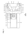
FIG. 1 is a plan view of a housing, on which a detecting member is mounted at an initial position, in a connector according to one embodiment of the present invention, -
FIG. 2 is a rear view of the housing on which the detecting member is mounted at the initial position, -
FIG. 3 is a plan view of the housing, -
FIG. 4 is a side view of the housing, -
FIG. 5 is a front view of the housing, -
FIG. 6 is a rear view of the housing, -
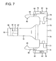
FIG. 7 is a plan view of the detecting member, -
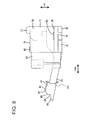
FIG. 8 is a side view of the detecting member, -
FIG. 9 is a front view of the detecting member, -
FIG. 10 is a bottom view of the detecting member, -
FIG. 11 is a section showing a state where the detecting member is mounted at the initial position and a housing main body is lightly connected to a mating housing, -
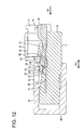
FIG. 12 is a section showing a state where the housing main body is further connected and a lock projection is pressed by a pressing surface of an interfering portion to resiliently deform a lock arm to a large extent, -
FIG. 13 is a section showing a state where the housing main body is properly connected to the mating housing, the lock arm is engaged with a lock receiving portion and the detecting member is kept at a standby position, -
FIG. 14 is a section showing a state where a guide surface of the lock projection is held in sliding contact with an upper end opening edge of an accommodating recess in the process of moving the detecting member toward a detection position, -
FIG. 15 is a section showing a state where the detecting member is located at the detection position and a protrusion is accommodated in the accommodating recess, -
FIG. 16 is a section of an essential part showing a state where the detecting member is retained in the housing main body at the initial position, -
FIG. 17 is a section of an essential part showing a state where a movement of the detecting member to the detection position is prevented at the initial position, -
FIG. 18 is a section of an essential part showing a state where a return movement of the detecting member to the initial position is prevented at the standby position, -
FIG. 19 is a side view with an essential part in section showing a state before the detecting member is mounted on the housing main body, and -
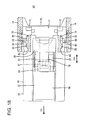
FIG. 20 is a side view with an essential part in section showing a state where the detecting member is mounted on the housing main body and the shake of a main portion is suppressed by first and second shake preventing portions. - One particular embodiment of the present invention is described with reference to
FIGS. 1 to 20 . A connector according to this embodiment includes ahousing 10 and amating housing 50 connectable to each other, and a detectingmember 70 to be mounted on or in thehousing 10. Note that, in the following description, sides of the twohousings - The
mating housing 50 is made e.g. of synthetic resin and includes a (particularly substantially tubular)receptacle 51 which is open forward as shown inFIG. 11 . Alock receiving portion 52 is formed in or on (particularly a front end part of the outer or upper wall of) thereceptacle 51. Thelock receiving portion 52 particularly penetrates through the receptacle 51 (particularly the upper wall) in a height direction HD (direction intersecting with a connecting direction CD of the twohousings 10, 50). The inner front surface of thelock receiving portion 52 serves as anengaging surface 53 which is a reverse tapered surface inclined slightly forward toward an upper or outer side. Further, an interferingportion 54 is formed at a position adjacent (particularly immediately before) thelock receiving portion 52 at the (particularly front end part of the outer or upper wall of) thereceptacle 51. Aninclined surface 55 which is a tapered surface inclined forward toward an upper or outer side is formed at (particularly a lower or inner end part of the front surface of) the interferingportion 54. Further, the lower or inner surface of the interferingportion 54 is arranged substantially horizontally (parallel to the connecting direction CD) from theinclined surface 55 to thelock receiving portion 52 and serves as apressing surface 56 capable of pressing aprotrusion 87 of the detecting member 70 (to be described later) and alock projection 24 of alock arm 12 from above or outside. - The
housing 10 is made e.g. of synthetic resin and includes a (particularly substantially block-shaped) housingmain body 11 and a resiliently deformable and (particularly substantially cantilever-shaped)lock arm 12 integrally or unitarily coupled to (particularly the upper surface of) the housingmain body 11 as shown inFIGS. 3 and4 . One or more unillustrated terminal fittings are at least partly insertable into the housingmain body 11. - A (particularly substantially arch-shaped or bent or gate-shaped)
protection wall 13 at least partly surrounding a rear end part (disengagingportion 28 to be described later) of thelock arm 12 is formed on the upper or outer surface of (particularly a rear end part of) the housingmain body 11 as shown inFIGS. 5 and6 . Theprotection wall 13 particularly is composed of or comprises a pair ofouter side walls 14 standing up or projecting from substantially opposite widthwise end parts of the upper surface of the housingmain body 11, a pair ofinner side walls 15 located at inner sides of the bothouter side walls 14 and standing up or projecting from the upper surface of the housingmain body 11, and a coveringwall 16 connected to (particularly the upper or distal ends of) the bothinner side walls 15 and/or the bothouter side walls 14 and particularly substantially extending over the entire width of the housingmain body 11. As shown inFIG. 19 , an inner space of theprotection wall 13 serves as amount space 17 into which the detectingmember 70 is to be at least partly inserted in an insertion direction ID (particularly parallel to the connecting direction CD), particularly substantially from behind. - As shown in
FIG. 3 , the coveringwall 16 particularly is formed with at least onecut portion 18 which is open on-the rear end of the coveringwall 16. The disengagingportion 28 of thelock arm 12 particularly can be at least partly seen through the cut portion(s) 18. Further, the rear ends of theinner side walls 15 particularly are located before the rear ends of theouter side walls 14 by being at least partly partitioned by thecut portion 18. - As shown in
FIGS. 5 and19 , one or more, particularly a pair ofguide grooves 19 are formed on (particularly the inner surface(s) of lower end part(s) of) the (particularly both) outer side wall(s) 14. The (both) guide groove(s) 19 particularly has/have a rectangular cross section, substantially extend in forward and backward directions FBD and/or is/are open on both front and rear ends of the (both) outer side wall(s) 14. One or more, particularly a pair offirst retaining portions 21 are formed to project inward on the inner surfaces of (particularly lower parts of the rear ends of) the (particularly both) guide groove(s) 19. As shown inFIG. 16 , the rear surface(s) of the first retaining portion(s) 21 particularly is/are tapered surface(s) inclined inwardly toward the front and the front surface(s) thereof extend substantially in a width direction WD (a direction at an angle different from 0° or 180°, preferably substantially perpendicular to the forward and backward directions FBD and/or the inserting direction ID and/or the connecting direction CD). - One or more, particularly a pair of
second retaining portions 22 are formed to project outward on the outer surface(s) of (particularly rear end part(s) of) the (particularly both) inner side wall(s) 15. As shown inFIGS. 5 and6 , the (both) second retaining portion(s) 22 particularly substantially is/are in the form of long and narrow ribs substantially extending upward or outward (particularly in a height direction HD or a direction at an angle different from 0° or 180°, preferably substantially perpendicular to the forward and backward directions FBD and/or the inserting direction ID and/or the connecting direction CD and/or the width direction WD) from the outer or upper surface of the housingmain body 11. As shown inFIG. 16 , the rear surface(s) of the second retaining portion(s) 22 particularly is/are tapered surface(s) inclined outwardly toward the front and/or the front surface(s) thereof particularly is/are reverse tapered surface(s) inclined slightly forwardly toward an outer side. - As shown in
FIG. 17 , one or more, particularly a pair of restrictingportions 23 are formed to project outward on (particularly the outer surface(s) of front end part(s) of) the (particularly both) inner side wall(s) 15. As shown inFIGS. 5 and6 , the (both) restricting portion(s) 23 particularly is/are in the form of long and narrow ribs substantially extending downward or inward in the height direction HD from the lower or inner surface of the coveringwall 16. The restricting portion(s) 23 particularly has/have a shorter projecting distance than the second retaining portion(s) 22 and/or a longer extending length than the second retaining portion(s) 22 and/or particularly is/are substantially arranged above or corresponding to the second retaining portion(s) 22. As shown inFIG. 17 , the rear surface(s) of the restricting portion(s) 23 particularly is/are tapered surface(s) inclined outwardly toward the front and/or the front surface(s) thereof is/are tapered surface(s) inclined inwardly toward the front. - As shown in
FIG. 4 , thelock arm 12 substantially extends backward or along the connecting direction CD from (particularly the upper or outer surface of a front end part of) the housingmain body 11. Thelock projection 24 is formed to project in the height direction HD in an intermediate part (particularly in a substantially central part) of thelock arm 12 in forward and backward directions FBD. Adeformation space 25 is formed between the lower or inner surface of thelock arm 12 and the upper or outer surface of the housingmain body 11. - As shown in
FIG. 3 , thelock arm 12 particularly includes a base end portion 26 (particularly substantially in the form of a rectangular plate) before thelock projection 24. As shown inFIG. 4 , a front end side of thebase end portion 26 is coupled to the upper surface of the housingmain body 11 and serves as a supporting point of resilient deformation of thelock arm 12. Further, as shown inFIGS. 3 and4 , thelock arm 12 includes one or more, particularly a pair ofcoupling portions 27 substantially extending backward from (particularly both sides of) thelock projection 24 and the disengagingportion 28 coupled to the rear end(s) of the (both) coupling portion(s) 27, substantially extending in the width direction WD and arranged to be slightly higher. The rear surface of thelock projection 24 serves as a lockingsurface 29 substantially facing backward, wherein an upper or outer side facing the engagingsurface 53 of thelock receiving portion 52 particularly is slightly reversely tapered and/or a lower or inner side facing a movement restricting surface 94 (to be described later) of the detectingmember 70 particularly is slightly tapered as shown inFIG. 11 . - When the two
housings FIG. 13 , thelock projection 24 at least partly is resiliently fitted into thelock receiving portion 52 from below or inside and the lockingsurface 29 is arranged to be able to come into contact with the engagingsurface 53, whereby the twohousings lock arm 12 is resiliently deformed to at least partly enter thedeformation space 25 by pressing the disengagingportion 28 from above or outside with the twohousings lock projection 24 exits from thelock receiving portion 52 and the twohousings - Further, as shown in
FIG. 11 , anaccommodating recess 31 is so formed on the lower surface of thelock arm 12 to be open backward. Theaccommodating recess 31 is so dimensioned and/or shaped that theprotrusion 87 of the detectingmember 70 at least partly is fittable thereinto, and is open on the lower or inner surface (facing toward the deformation space 25) of thelock arm 12 and/or the rear surface of thelock projection 24. The inner upper surface of theaccommodating recess 31 particularly is located higher than the upper surface of thebase end portion 26 of thelock arm 12. Further, the inner upper surface of theaccommodating recess 31 particularly is partly recessed to form anauxiliary recess 32. As shown inFIG. 6 , theauxiliary recess 32 is arranged in a widthwise intermediate part (particularly in a widthwise central part) of the inner upper surface of theaccommodating recess 31 and has a width which particularly is leass than about half (particularly which is about 1/3) of the entire width of theaccommodating recess 31. A depth of theauxiliary recess 32 is set to be sufficiently smaller than that of theaccommodating recess 31. - Next, the detecting
member 70 is described. The detectingmember 70 is likewise made e.g. of synthetic resin and includes amain portion 71 and aresilient arm portion 72 integrally or unitarily coupled to (particularly the front end of) themain portion 71 as shown inFIGS. 7 and8 . The detectingmember 70 is to be mounted on or in the housingmain body 11 movably from an initial position IP to a detection position DP via a standby position SP. - As shown in
FIGS. 2 and9 , themain portion 71 includes arear portion 73 substantially extending in the width direction WD and/or the height direction HD. Therear portion 73 is formed with adisengagement window 74. Thedisengagement window 74 particularly is a recess having a substantially angular U-shaped cross section and/or formed in a widthwise intermediate part (particularly in a substantially widthwise central part) of the upper end edge of therear portion 73. When the detectingmember 70 mounted on the housingmain body 11 is viewed from behind, the disengagingportion 28 of thelock arm 12 can be at least partly seen through thedisengagement window 74. - Further, the
rear portion 73 includes one or more, particularly a pair ofvertical portions 75 substantially extending in the height direction HD at opposite widthwise end parts and/or ahorizontal portion 76 particularly coupled to rear end parts of the bothvertical portions 75 and/or substantially extending in the width direction WD. Thedisengagement window 74 is partitioned by the bothvertical portions 75 and thehorizontal portion 76. The rear surfaces of the bothvertical portions 75 and thehorizontal portion 76 are arranged substantially along the height direction HD and can be pressed or operated (particularly in the inserting direction ID or from behind) during a movement to the detection position DP. A pair of catchingportions 77 are formed to project on the upper ends of the bothvertical portions 75. The both catchingportions 77 are or can be caught by fingers or a jig and a displacement force (particularly a backward pulling force) acts on the both catchingportions 77 in that state, whereby the detectingmember 70 is or can be displaced (pulled back) from the detection position DP to the initial position IP. - As shown in
FIG. 8 , the bothvertical portions 75 particularly have a substantially rectangular side view and include one or more, particularly a pair ofguide portions 78 on (particularly lower end parts of the outer surfaces of) thevertical portions 75. Theguide portions 78 particularly substantially are in the form of ribs substantially extending in forward and backward directions FBD particularly over the substantially entire length of thehorizontal portion 76. As shown inFIG. 10 , one or more, particularly a pair of first stoppingportions 79 are formed on (particularly a lower part, further particularly on substantially lower halves of) the both guideportions 78. The rear surfaces of the first stoppingportions 79 substantially extend in the width direction WD. Each of the both guideportions 78 includesgroove portions 81 located at both front and rear sides of the first stoppingportion 79, substantially extending in forward and backward directions FBD and/or open on both front and rear ends. - As shown in
FIGS. 8 and9 , one or more, particularly a pair of firstshake preventing portions 82 are formed to project at one or more positions at least partly overlapping with the (particularly both) first stopping portion(s) 79 in forward and backward directions FBD on (particularly the upper surfaces of rear parts of) the (both) guideportions 78. The (both) first shake preventing portion(s) 82 particularly is/are in the form of ribs substantially extending in forward and backward directions FBD and/or substantially having a triangular or pointed cross section and/or arranged adjacent to thw widthwise end part(s) of themain portion 71, particularly on lower rear sides of opposite widthwise end parts of themain portion 71. - Further, one or more, particularly a pair of second
shake preventing portions 83 are formed to project on the vertical portion(s) 75, particularly substantially on the upper end surfaces of front parts of the bothvertical portions 75. The secondshake preventing portions 83 particularly are in the form of ribs substantially extending in forward and backward directions FBD and/or substantially having a triangular or pointed cross section and/or particularly have a size slightly smaller than the first shake preventing portion(s) 82. The (particularly both) second shake preventing portion(s) 83 is/are arranged adjacent to the widthwise end part(s) of themain portion 71, particularly on upper front sides of the opposite widthwise end parts of themain portion 71. In the moving process of the detectingmember 70, the (both) first shake preventing portion(s) 82 is/are held in sliding contact with the inner upper surfaces of the (both) guide groove(s) 19 while being squeezed and/or the (both) second shake preventing portion(s) 83 is/are held in sliding contact with the lower surface of the coveringwall 16 while being squeezed, whereby a moving posture of the detectingmember 70 particularly substantially is corrected to a proper posture. - Further, as shown in
FIG. 7 , one or more, particularly a pair ofresilient pieces 84 are formed to substantially project forward on (particularly the front ends of) the (both) vertical portion(s) 75. As shown inFIG. 8 , the (both) resilient piece(s) 84 particularly is/are in the form of plate(s) having a substantially rectangular side view and/or resiliently deformable substantially in the width direction WD with the front end(s) of the vertical portion(s) 75 as supporting point(s). As shown inFIG. 9 , one or more, particularly a pair ofpartial locking portions 85 and one or more, particularly a pair of second stoppingportions 86 are formed substantially side by side in the height direction HD on (particularly front end parts of) the (both) resilient piece(s) 84. - The partial locking portion(s) 85 project(s) inward from (particularly substantially upper halves of front end parts of) the resilient piece(s) 84 and substantially extend(s) in the height direction HD. As shown in
FIG. 7 , the rear surface(s) of the partial locking portion(s) 85 particularly is/are tapered surface(s) inclined inwardly toward the front, and/or the front surface(s) thereof is/are tapered surface(s) inclined outwardly toward the front. As shown inFIG. 17 , when the detectingmember 70 is at the initial position IP, the front surface(s) of the (both) partial locking portion(s) 85 is/are held in contact with the (both) restricting portion(s) 23 from behind in a semi-locking state, whereby a movement of the detectingmember 70 to the detection position DP is (particularly secondarily or additionaly) prevented. Further, as shown inFIG. 18 , when the detectingmember 70 is at the detection position DP, the rear surface(s) of the (both) partial locking portion(s) 85 is/are in contact with the (both) restricting portion(s) 23 from front in a semi-locking state, whereby a movement of the detectingmember 70 to the initial position IP is (particularly secondarily or additionally) prevented. - As shown in
FIG. 9 , the second stopping portion(s) 86 project(s) inward from (particularly substantially lower halves of front end parts of) the resilient piece(s) 84 and/or substantially extend in the height direction HD. As shown inFIG. 10 , the second stopping portion(s) 86 particularly is/are slightly smaller than the partial locking portion(s) 85. The rear surface(s) of the second stopping portion(s) 86 particularly is/are reverse tapered surface(s) inclined slightly backwardly toward an inner side. As shown inFIG. 16 , when the detectingmember 70 is at the initial position IP, the rear surface(s) of the first stopping portion(s) 79 particularly is/are held in contact with the first retaining portion(s) 21 from front and/or the rear surface(s) of the second stopping portion(s) 86 particularly is/are held in contact with the second retaining portion(s) 22 from front, thereby preventing the detectingmember 70 from being detached from or displaced within the housingmain body 11. - As shown in
FIG. 8 , theresilient arm portion 72 particularly substantially extends forward in a cantilever manner from a widthwise intermediate part (particularly a substantially widthwise central part of the front end) of themain portion 71. Theresilient arm portion 72 particularly is substantially in the form of a rectangular bar and/or resiliently deformable in a deforming direction DD (e.g. the height direction HD or inner and outer directions) particularly with a rear end part connected to the front end of themain portion 71 as a supporting point. In a natural state, theresilient arm portion 72 particularly is inclined upwardly or outwardly at a substantially constant angle of inclination from the rear end to the front end of theresilient arm portion 72. On the other hand, as shown inFIGS. 11 to 13 , theresilient arm portion 72 is resiliently deformed along the deforming direction DD to gradually make its angle of inclination smaller as the detectingmember 70 is displaced from the initial position IP to the standby position SP. Then, as shown inFIG. 15 , theresilient arm portion 72 particularly is substantially in a horizontal posture without being substantially inclined when the detectingmember 70 reaches the detection position DP. Thus, theresilient arm portion 72 particularly is in a state to accumulate a resilient force at the standby position SP and the detection position DP. - As shown in
FIG. 8 , the protrusion 87 (particularly substantially in the form of a rectangular block) is formed to project upward or outward on or near a front or distal end part of theresilient arm portion 72. A taperedguide surface 88 inclined upwardly or outwardly toward the back is formed on an upper or outer end part of the front surface of theprotrusion 87. As shown inFIG. 13 , when the detectingmember 70 is at the standby position SP, theguide surface 88 of theprotrusion 87 particularly is arranged to substantially face an upper or outer end opening edge of theaccommodating recess 31 on the rear surface of thelock projection 24 from behind. Further, as shown inFIG. 14 , in the process of moving the detectingmember 70 from the standby position SP to the detection position DP, theguide surface 88 of theprotrusion 87 slides on (particularly the upper or outer end opening edge of) theaccommodating recess 31 and, accordingly, theresilient arm portion 72 is resiliently inclined. Furthermore, as shown inFIG. 15 , when the detectingmember 70 reaches the detection position DP, theprotrusion 87 is positioned and at least partly inserted into theaccommodating recess 31. A tapered guidedsurface 34 substantially facing theguide surface 88 of theprotrusion 87 at the detection position DP is formed on the inner surface of theaccommodating recess 31. - Further, as shown in
FIGS. 8 and9 , anauxiliary protrusion 91 particularly is formed to partly project on the upper end surface of theprotrusion 87. Theauxiliary protrusion 91 particularly is in the form of a rib substantially extending in forward and backward directions FBD on a widthwise intermediate part (particularly a substantially widthwise central part) of the upper end surface of theprotrusion 87. A projecting distance of theauxiliary protrusion 91 is set to be sufficiently smaller than that of theprotrusion 87. When theprotrusion 87 at least partly is inserted into theaccommodating recess 31, theauxiliary protrusion 91 at least partly is fitted and inserted into theauxiliary recess 32. - The front surface of the
auxiliary protrusion 91 serves as a taperedauxiliary guide surface 92 inclined upwardly or outwardly toward the back. Theauxiliary guide surface 92 is substantially flush and continuous with theguide surface 88 and/or has substantially the same angle of inclination as theguide surface 88. In the process of moving the detectingmember 70 from the standby position SP to the detection position DP, theauxiliary guide surface 92 particularly comes into sliding contact with the upper or outer end opening edge of theaccommodating recess 31, following theguide surface 88. Thus, the amount of resilient deformation of theresilient arm portion 72 particularly is increased by as much as theauxiliary protrusion 91. Note that an area of the upper surface of theauxiliary protrusion 91 behind theauxiliary guide surface 92 is a tapered surface inclined downwardly toward the back. - Further, a
contact portion 93 is formed to project forward on a lower end part of the front end of theprotrusion 87. As shown inFIG. 7 , thecontact portion 93 particularly substantially has a rectangular plan view. When the detectingmember 70 is at the initial position IP, the upper or outer surface of thecontact portion 93 is arranged substantially horizontally and/or comes into contact with the inner upper surface of theaccommodating recess 31 from below. In this way, theresilient arm portion 72 is slightly resiliently deformed with a pre-load applied to thelock arm 12. - As shown in
FIG. 8 , amovement restricting surface 94 is formed between theguide surface 88 and thecontact portion 93 on the front surface of theprotrusion 87. Themovement restricting surface 94 is arranged substantially along the height direction HD when theresilient arm portion 72 is in a natural state. Further, as shown inFIG. 11 , when the detectingmember 70 is at the initial position IP, themovement restricting surface 94 of theprotrusion 87 is arranged to face the lockingsurface 29 of thelock projection 24 from behind. - Next, functions of the connector according to this embodiment are described.
- In mounting the detecting
member 70, the detectingmember 70 at least partly is inserted into themount space 17 of the housingmain body 11 in the inserting direction ID, particularly substantially from behind. In a mounting process, the first shake preventing portion(s) 82 come(s) into sliding contact with the inner upper surface(s) of the guide groove(s) 19 while being squeezed and/or the second shake preventing portion(s) 83 come(s) into sliding contact with the lower surface of the coveringwall 16 while being squeezed, thereby ensuring stability in the mounting posture of the detectingmember 70. - Further, in the mounting process, the (both) resilient piece(s) 84 is/are resiliently deformed and the detecting
member 70 reaches the initial position IP as shown inFIG. 16 , whereby the (both) resilient piece(s) 84 at least partly is/are resiliently restored and/or the second stopping portion(s) 86 is/are arranged to be engageable with the second stopping portion(s) 22 from front. Particularly simultaneously, the first stopping portion(s) 79 is/are arranged to be engageable with the first retaining portion(s) 21 from front. In this way, the detectingmember 70 is prevented from being detached (e.g. backward) from the housingmain body 11. Further, when the detectingmember 70 reaches the initial position IP, themovement restricting surface 94 of theprotrusion 87 is arranged to be engageable with the lockingsurface 29 of thelock projection 24 particularly substantially from behind as shown inFIG. 11 . Thus, if it is tried to push the detectingmember 70 in the inserting direction ID or forward at the initial position IP, themovement restricting surface 94 comes into contact with the lockingsurface 29 to prevent any further (forward) movement of the detectingmember 70. At this time, as shown inFIG. 17 , a forward movement of the detectingmember 70 at the initial position IP particularly is secondarily prevented also by the contact of thepartial locking portions 85 with the restrictingportions 23 from behind. In this way, as shown inFIG. 1 , the detectingmember 70 is held or positioned at the initial position IP with respect to the housingmain body 11 with movements in forward and backward directions FBD prevented. - At the initial position IP, as shown in
FIG. 11 , thecontact portion 93 of theresilient arm portion 72 comes into contact with the inner upper surface of theaccommodating recess 31 and theresilient arm portion 72 is held with respect to thelock arm 12 while accumulating a resilient force. Then, thecontact portion 93 comes into contact with the inner upper surface of theaccommodating recess 31, whereby an overlap margin between themovement restricting surface 94 of theprotrusion 87 and the lockingsurface 29 of thelock projection 24 is automatically determined at a specified (predetermined or predeterminable) value. - Subsequently, the housing
main body 11 is fitted into thereceptacle 51 of themating housing 50. In a fitting process, after coming into sliding contact with theinclined surface 55 of the interferingportion 54, thelock projection 24 is pressed by thepressing surface 56 of the interferingportion 54 and thelock arm 12 is resiliently deformed to at least partly enter thedeformation space 25 as shown inFIG. 12 . Then, when the housingmain body 11 is properly connected to themating housing 50, thelock projection 24 is released from a state pressed by the interferingportion 54, whereby thelock arm 12 is resiliently at least partly restored and thelock projection 24 at least partly is fitted into thelock receiving portion 52 from inside or below as shown inFIG. 13 . In this way, an upper or outer part of the lockingsurface 29 of thelock projection 24 is arranged to be engageable with the engagingsurface 53 of thelock receiving portion 52 and the twohousings - Further, when the housing
main body 11 is properly connected to themating housing 50, theauxiliary protrusion 91 on the upper end surface of theprotrusion 87 is pressed inwardly or downwardly by thepressing surface 56 of the interferingportion 54 as shown inFIG. 13 . At this time, theprotrusion 87 is kept in contact with the interferingportion 54 without following reciprocal displacements of thelock arm 12 and thecontact portion 93 exits from theaccommodating recess 31. In this way, the detectingmember 70 particularly is kept at the standby position SP where theresilient arm portion 72 is separated from thelock arm 12 and held in contact with themating housing 50. At the standby position SP, theresilient arm portion 72 is resiliently deformed by the interferingportion 54 and particularly substantially takes an inclined posture approximate to a horizontal posture. - Further, at the standby position SP, the
guide surface 88 of theprotrusion 87 particularly is arranged to substantially face the upper or outer end opening edge of theaccommodating recess 31 on the rear surface of thelock projection 24 from behind while forming a small clearance as shown inFIG. 13 . That is, the upper end opening edge of theaccommodating recess 31 is arranged to be accommodated within the height range of theguide surface 88 of theprotrusion 87. - Subsequently, the rear surface of the
rear portion 73 is displaced or pushed in the inserting direction ID or forward to bring the detectingmember 70 to the detection position DP. By applying a forward pushing force to the detectingmember 70 at the standby position SP, a semi-locking state between thepartial locking portions 85 and the restrictingportions 23 is released and theresilient pieces 84 are resiliently deformed to move onto the restrictingportions 23. Further, in the process of movement to or toward the detection position DP, theguide surface 88 of theprotrusion 87 and theauxiliary guide surface 92 of theauxiliary protrusion 91 successively come into sliding contact with the upper end opening edge of theaccommodating recess 31 as shown inFIG. 14 , whereby theresilient arm portion 72 particularly is resiliently deformed to a larger extent and inserted deeper into thedeformation space 25 and, further, theprotrusion 87 is inserted into theaccommodating recess 31 from behind. - When the detecting
member 70 substantially reaches the detection position DP, theprotrusion 87 particularly is substantially entirely fitted and accommodated into theaccommodating recess 31 and theauxiliary protrusion 91 particularly is likewise fitted and accommodated into theauxiliary recess 32 as shown inFIG. 15 . Theprotrusion 87 comes into contact with the inner front surface of theaccommodating recess 31, thereby preventing any further forward movement of the detectingmember 70. Further, at the detection position DP, the resilient piece(s) 84 is/are resiliently at least partly restored and/or the partial locking portion(s) 85 come(s) into contact with the restricting portion(s) 23 from front as shown inFIG. 18 , thereby preventing a backward movement of the detectingmember 70. In this way, the detectingmember 70 is kept or positioned at the detection position DP. - Further, at the detection position DP, the
resilient arm portion 72 particularly is held substantially in a horizontal posture in a state where a resilient force is accumulated between thelock arm 12 and the housingmain body 11 as shown inFIG. 15 . Theresilient arm portion 72 is inserted to a proper depth into thedeformation space 25, thereby restricting resilient deformation of thelock arm 12, with the result that the twohousings member 70 from the initial position IP to the detection position DP via the standby position SP, the first shake preventing portion(s) 82 come into sliding contact with the inner upper surface(s) of the guide groove(s) 19 while being squeezed and/or the second shake preventing portion(s) 83 come(s) into sliding contact with the lower surface of the coveringwall 16 while being squeezed, whereby the inclination of themain portion 71 is avoided and stability in the moving posture of the detectingmember 70 is ensured. Further, at each of the initial position IP, the standby position SP and the detection position DP, the shaking of themain portion 71 particularly is suppressed by a shake preventing function of the first and secondshake preventing portions member 70 is positioned and held on the housingmain body 11 as shown inFIGS. 2 and20 . - On the other hand, if the housing
main body 11 is kept at a partially connected position without being properly connected to themating housing 50, thelock arm 12 is pressed by thepressing surface 56 of the interferingportion 54 and kept resiliently deformed in thedeformation space 25 as shown inFIG. 12 . Accordingly, even if it is tried to displace or push the detectingmember 70 in the inserting direction or forward in this state, theresilient arm portion 72 cannot enter thedeformation space 25 due to the interference of theprotrusion 87 with thelock projection 24 and a movement of the detectingmember 70 to the detection position DP is hindered. Thus, whether or not the housingmain body 11 has been properly connected to themating housing 50 can be known or detected based on whether or not the detectingmember 70 is movable or displaceable toward or to the detection position DP. - In separating the both
housings member 70 is dsiplaced or pulled backward in that state. If a backward pulling force acts on the detectingmember 70, thepartial locking portions 85 and the restrictingportions 23 are disengaged while theresilient pieces 84 are resiliently deformed, and the detectingmember 70 is pulled back toward or to the initial position IP. Subsequently, the fingers or the jig are/is or can be at least partly inserted into thedisengagement window 74 and placed on (interact with) the disengagingportion 28 to press down or displace the disengagingportion 28. In this way, thelock projection 24 is deformed or separated from thelock receiving portion 52 and thelock arm 12 and thelock receiving portion 52 are or can be disengaged. By pulling the housingmain body 11 apart from themating housing 50 with the disengagingportion 28 pressed down or displaced, the twohousings wall 16 is present above the disengagingportion 28 and thecut portion 18 does not have a sufficient opening area for allowing the entrance of the fingers or the jig, wherefore the entrance of the fingers or the jig from above is prevented. - As described above, the following effects can be achieved according to this embodiment.
- When the detecting
member 70 is at the initial position IP, theresilient arm portion 72 comes into contact with the lock arm 12 (particularly substantially in the height direction HD) to apply a pre-load and, accordingly, theresilient arm portion 72 is arranged at a position to be able to come into contact with thelock arm 12 from behind and an overlap margin with thelock arm 12 is properly determined. Thus, even if dimensions of the detectingmember 70 are not strictly managed, detection reliability can be improved, thereby improving overall operability. - Here, when the detecting
member 70 is at the standby position SP, theprotrusion 87 of theresilient arm portion 72 is arranged at a position at least partly overlapping with thelock arm 12 along the deforming direction DD (particularly substantially in the height direction HD) and theguide surface 88 of theprotrusion 87 comes into sliding contact with thelock arm 12 in the moving process or transition from the standby position SP to the detection position DP. Thus, the precision of position accuracy of theprotrusion 87 at the standby position SP particularly is required. In that aspect, according to this embodiment, theresilient arm portion 72 comes into contact with the lock arm 12 (particularly substantially in the height direction HD) at the initial position IP. Therefore, position accuracy of theprotrusion 87 can be advantageously satisfied. - Further, the detecting
member 70 particularly includes themain portion 71 to be pressed during the movement toward or to the detection position DP, themain portion 71 comes into sliding contact with the housingmain body 11 in the moving process of the detectingmember 70, and the first and/or secondshake preventing portions main portion 71 out of both slide-contact surfaces of themain portion 71 and/or the housingmain body 11 and squeezable against the slide-contact surface of the housingmain body 11 in the height direction. Thus, the shake of the detecting member 70 (particularly substantially in the height direction HD) is or can be prevented. As a result, detection reliability of the detectingmember 70 is further improved. - Further, since the first and second
shake preventing portions member 70 in forward and backward directions FBD is prevented and stability in the posture of the detectingmember 70 is ensured. - Since the
protrusion 87 particularly at least partly is accommodated into theaccommodating recess 31 of thelock arm 12 when the detectingmember 70 reaches the detection position DP, thelock arm 12 and the detectingmember 70 are arranged at positions at least partly overlapping along the deforming direction DD (particularly substantially in the height direction HD) and the corresponding dimension (particularly height) of the connector can be reduced. In this case, theaccommodating recess 31 is open toward thedeformation space 25 of thelock arm 12 and toward the back, but not open on the front end part connected to the housingmain body 11, wherefore a reduction in the strength of thelock arm 12 is avoided. As a result, locking reliability by thelock arm 12 is improved. - Since the
lock projection 24 particularly is formed to project along the deforming direction DD (particularly in the height direction HD) on thelock arm 12 and theaccommodating recess 31 is open on the rear surface of thelock projection 24, a large opening area of theaccommodating recess 31 can be ensured along the deforming direction DD, within the corresponding dimension of thelock projection 24, particularly in the height direction HD within the height range of thelock projection 24. - Since the
protrusion 87 and thelock projection 24 particularly are arranged at the positions at least partly overlapping along the deforming direction DD (particularly substantially in the height direction HD) when the detectingmember 70 is at the standby position SP, the corresponding dimension (particularly height) of the connector can be further reduced. - In the process of moving or displacing the detecting
member 70 from the standby position SP to the detection position DP, theguide surface 88 of theprotrusion 87 comes into sliding contact with the upper or outer end opening edge of theaccommodating recess 31 to substantially guide the insertion of theprotrusion 87 into theaccommodating recess 31. Thus, stability in the moving operation of the detectingmember 70 is ensured. - Since the
auxiliary protrusion 91 particularly is formed to project in the deforming direction DD or the height direction HD on a part of the upper end of theprotrusion 87 and/or theauxiliary guide surface 92 continuous with theguide surface 88 particularly is formed on the front surface of theauxiliary protrusion 91, a large guide area can be ensured in the deforming direction DD or the height direction HD and/or dimensional management in positioning theprotrusion 87 to face the opening edge of theaccommodating recess 31 at the standby position SP can be facilitated. Further, theauxiliary protrusion 91 at least partly is inserted into theaccommodating recess 31 in addition to theprotrusion 87 and the depth of theaccommodating recess 31 is increased by as much as the height of theauxiliary protrusion 91, wherefore the strength of thelock arm 12 may be reduced. However, according to this embodiment, a part of the inner upper surface of theaccommodating recess 31 particularly is only recessed to form the auxiliary recess into which theauxiliary protrusion 91 at least partly is fitted at the detection position DP. Thus, the depth of the entireaccommodating recess 31 is not increased and a reduction in the strength of thelock arm 12 can be suppressed. - The surface of the disengaging
portion 28 opposite to the surface facing thedeformation space 25 particularly is at least partly covered by theprotection wall 13 and an inadvertent operation of the disengagingportion 28 is prevented by theprotection wall 13, whereas the disengagingportion 28 can be operated e.g. by placing fingers or the jig through thedisengagement window 74 that is open on therear portion 73 of the detectingmember 70 in disengaging thelock arm 12. Thus, thelock arm 12 can be easily released from the locked state. - Further, in pulling the
mating housing 50 apart from the housingmain body 11, the detectingmember 70 particularly is or can be pulled back to the initial position IP by catching the catchingportions 77 of therear portion 73 e.g. with fingers or the jig and, thereafter, the disengagingportion 28 can be operated. In this case, since the pair of catchingportions 77 particularly are arranged at the opposite sides of thedisengagement window 74 on therear portion 73, space efficiency of therear portion 73 is improved and the miniaturization of the connector can be met. - Accordingly, to facilitate an operation of releasing an engaged state of a lock arm, a
protection wall 13 stands up or projects from a housing main body 11 (particularly from or near a rear end part of the housing main body 11) and restricts an operation of a disengagingportion 28 of alock arm 12 by at least partly covering the disengagingportion 28. A detectingmember 70 is made movable or displaceable to a detection position DP by being pushed in an inserting direction ID (e.g. substantially forward) when the housingmain body 11 is properly connected to amating housing 50. Further, the detectingmember 70 includes arear portion 73 located adjacent to (e.g. behind) thelock arm 12 and to be operated (e.g. pushed) when the detectingmember 70 is moved to the detection position. Adisengagement window 74 used to operate the disengagingportion 28 is formed on a position of therear portion 73 adjacent to (e.g. behind) the disengagingportion 28. - The present invention is not limited to the above described and illustrated embodiment. For example, the following embodiments are also included in the technical scope of the present invention.
- (1) The detecting member may be configured to be incapable of restricting the resilient deformation of the lock arm when the detecting member reaches the detection position.
- (2) The accommodating recess may not be so dimensioned and shaped that the protrusion is fittable thereinto and may be so dimensioned that the protrusion is loosely fitted thereinto.
- (3) The accommodating recess may be open backward on a part of the lock arm other than the lock projection.
- (4) The shake preventing portions may be formed on the housing main body instead of being formed on the main portion. Further, the shake preventing portions may be formed on both the main portion and the housing main body.
- (5) A plurality of shake preventing portions may be arranged substantially side by side on the same axes in forward and backward directions FBD and/or the height direction HD.
- (6) Three or more shake preventing portions may be arranged substantially side by side in forward and backward directions FBD and/or the height direction HD.
- (7) A plurality of auxiliary protrusions may be formed on the upper end of the protrusion. For example, a pair of auxiliary protrusions may be formed on opposite widthwise sides of the upper end of the protrusion. In this case, a plurality of auxiliary recesses may be formed at positions of the accommodating recess corresponding to the auxiliary protrusions.
- (8) The guide surface and the guide inclined surface may be curved inclined surfaces.
-
- 10 ...
- housing
- 11 ...
- housing main body
- 12 ...
- lock arm
- 13 ...
- protection wall
- 24 ...
- lock projection
- 25 ...
- deformation space
- 28 ...
- disengaging portion
- 31 ...
- accommodating recess
- 32 ...
- auxiliary recess
- 50 ...
- mating housing
- 52 ...
- lock receiving portion
- 70 ...
- detecting member
- 71 ...
- main portion
- 72 ...
- resilient arm portion
- 73 ...
- rear portion
- 74 ...
- disengagement window
- 77 ...
- catching portion
- 82 ...
- first shake preventing portion (shake preventing portion)
- 83 ...
- second shake preventing portion (shake preventing portion)
- 87 ...
- protrusion
- 88 ...
- guide surface
- 91 ...
- auxiliary protrusion
- 92 ...
- auxiliary guide surface
Claims (15)
- A connector, comprising:a housing main body (11) to be connected to a mating housing (50);a lock arm (12) projecting from the housing main body (11), resiliently deformable in a deforming direction (DD) intersecting with a connecting direction (CD) of the housing main body (11) with the mating housing (50), forming a deformation space (25) between the lock arm (12) and the housing main body (11), configured to hold the housing main body (11) connected to the mating housing (50) in a connected state (CS) by being resiliently engaged with a lock receiving portion (52) of the mating housing (50), and including a disengaging portion (28) to be operated in releasing an engaged state with the lock receiving portion (52);at least one protection wall (13) projecting from the housing main body (11) and configured to restrict an operation of the disengaging portion (28) by at least partly covering a surface of the disengaging portion (28) at a side substantially opposite to a surface facing the deformation space (25); anda detecting member (70) to be mounted on or to the housing main body (11) movably from an initial position (IP) to a detection position (DP), configured such that a movement in a displacement direction (ID) is restricted at the initial position (IP) before the housing main body (11) is connected to the mating housing (50) and a movement restricted state at the initial position (IP) is released and the detecting member (70) is capable of reaching the detection position (DP) by being displaced in the displacement direction (ID) when the housing main body (10) is properly connected to the mating housing (50), and including an adjacent portion (73) located adjacent the lock arm (12) and to be operated when the detecting member (70) is moved to the detection position (DP) and at least one disengagement window (74) formed on a position of the adjacent portion (73) adjacent to the disengaging portion (28) and used to operate the disengaging portion (28).
- A connector according to claim 1, wherein the lock arm (12) extends backward in a cantilever manner from a front end part of the housing main body (11).
- A connector according to any one of the preceding claims, wherein the disengaging portion (28) is formed on a rear end part of the lock arm (12).
- A connector according to any one of the preceding claims, wherein the adjacent portion (73) is a rear portion (73) which is located behind the lock arm (12) and wherein the disengagement window (74) is formed on a position of the rear portion (73) substantially behind the disengaging portion (28).
- A connector according to any one of the preceding claims, wherein the adjacent portion (72) is formed with a pair of catching portions (77) located at substantially opposite sides of the disengagement window (74).
- A connector according to any one of the preceding claims, wherein the one or more catching portions (77) are catchable by fingers or a jig in moving the detecting member (70) in a return direction opposite to the displacement direction (ID) to the detection position (DD).
- A connector according to any one of the preceding claims, wherein the disengagement window (74) is a recess having a substantially angular U-shaped cross section and/or formed in a widthwise intermediate part of the adjacent portion (73).
- A connector according to any one of the preceding claims, wherein the disengaging portion (28) of the lock arm (12) can be at least partly seen through the disengagement window (74) when the detecting member (70) mounted on the housing main body (11) is viewed from a mounting side.
- A connector according to any one of the preceding claims, wherein the detecting member (70) is configured such that (i) the insertion movement is restricted at the initial position (IP) by the contact of a resilient arm portion (72) of the detecting member (70) with the lock arm (12) before the housing main body (11) is connected to the mating housing (50); (ii) the movement restricted state at the initial position (IP) is released and the detecting member (70) is capable of reaching the detection position (DP) where the resilient arm portion (72) at least partly enters the deformation space (25) by being displaced from the initial position (IP) when the housing main body (11) is properly connected to the mating housing (50); and/or (iii) the resilient arm portion (72) is held in contact with the lock arm (12) in the deforming direction (DD) at the initial position (IP) to apply a pre-load to the lock arm (12).
- A connector according to any one of the preceding claims, wherein the lock arm (12) includes an accommodating recess (31) which is open toward the deformation space (25) and/or toward the back, and wherein the detecting member (70) is configured such that: (i) a movement in a movement direction (ID) is restricted at the initial position (IP) by the contact thereof with the lock arm (12) along the movement direction (ID) before the housing main body (11) is connected to the mating housing (50); (ii) a movement restricted state at the initial position (IP) is released and the detecting member (70) is kept at the standby position (SP) to substantially face the accommodating recess (31) along the movement direction (ID) when the housing main body (11) is properly connected to the mating housing (50); and (iii) the detecting member (70) reaches the detection position (DP) by a displacement operation in the movement direction (ID) from the standby position (SP), whereby at least one part of the detecting member (70) is inserted into the accommodating recess (31).
- A connector assembly comprising:a connector according to any one of the preceding claims, having a housing (10); anda mating connector having a mating housing (50) connectable with the housing (10), the mating housing (50) having a lock receiving portion (52) engageable with the lock arm (12) to lock the housings (10; 50) in the connected state (CS).
- A method of assembling a connector assembly, comprising the following steps:providing a connector having a housing main body (11) and a lock arm (12) projecting from the housing main body (11) and being resiliently deformable in a deforming direction (DD) intersecting with a connecting direction (CD) of the housing main body (11) with the mating housing (50), forming a deformation space (25) between the lock arm (12) and the housing main body (11);providing a mating connector having a mating housing (50);matingly connecting the housing main body (11) with the mating housing (50) thereby resiliently engaging the lock arm (12) with a lock receiving portion (52) of the mating housing (50) to hold the housing main body (11) and the mating housing (50) in a connected state (CS), wherein the lock arm (12) includes a disengaging portion (28) to be operated in releasing an engaged state with the lock receiving portion (52), and wherein at least one protection wall (13) projects from the housing main body (11) and is configured to restrict an operation of the disengaging portion (28) by at least partly covering a surface of the disengaging portion (28) at a side substantially opposite to a surface facing the deformation space (25); andmounting a detecting member (70) on or to the housing main body (11) movably from an initial position (IP) to a detection position (DP), wherein the detecting member (70) is configured such that a movement in a displacement direction (ID) is restricted at the initial position (IP) before the housing main body (11) is connected to the mating housing (50) and a movement restricted state at the initial position (IP) is released and the detecting member (70) is capable of reaching the detection position (DP) by being displaced in the displacement direction (ID) when the housing main body (10) is properly connected to the mating housing (50), and wherein the detecting member (70) further includes an adjacent portion (73) located adjacent the lock arm (12) and to be operated when the detecting member (70) is moved to the detection position (DP), and at least one disengagement window (74) formed on a position of the adjacent portion (73) adjacent to the disengaging portion (28) and used to operate the disengaging portion (28).
- A method of disassembling an assembled connector assembly, comprising:providing an assembled connector assembly of a connector and a mating connector, wherein the connector comprises a housing main body (11) and a lock arm (12) projecting from the housing main body (11) and being resiliently deformable in a deforming direction (DD) intersecting with a connecting direction (CD) of the housing main body (11) with the mating housing (50), forming a deformation space (25) between the lock arm (12) and the housing main body (11); and wherein the a mating connector comprises a mating housing (50) matingly connected with the housing main body (11) whereby the lock arm (12) of the housing main body (11) is resiliently engaged with a lock receiving portion (52) of the mating housing (50) to hold the housing main body (11) and the mating housing (50) in a connected state (CS); and wherein a detecting member (70) is mounted on or to the housing main body (11) movably from an initial position (IP) to a detection position (DP) and includes an adjacent portion (73) located adjacent the lock arm (12) and to be operated when the detecting member (70) is moved to the detection position (DP),releasing an engaged state of the lock arm (12) with the lock receiving portion (52) by operating a disengaging portion (28) of the lock arm (12) through at least one disengagement window (74) formed on a position of the adjacent portion (73) adjacent to the disengaging portion (28), wherein at least one protection wall (13) projects from the housing main body (11) and is configured to restrict an operation of the disengaging portion (28) by at least partly covering a surface of the disengaging portion (28) at a side substantially opposite to a surface facing the deformation space (25); anddisassembling the connector and the mating connector.
- A method according to claim 13, wherein the detecting member (70) is configured such that a movement in a displacement direction (ID) is restricted at the initial position (IP) before the housing main body (11) is connected to the mating housing (50) and a movement restricted state at the initial position (IP) is released and the detecting member (70) is capable of reaching the detection position (DP) by being displaced in the displacement direction (ID) when the housing main body (10) is properly connected to the mating housing (50).
- A method according to any one of the preceding claims 12 to 14, wherein the lock arm (12) extends backward in a cantilever manner from a front end part of the housing main body (11), and/or wherein the disengaging portion (28) is formed on a rear end part of the lock arm (12), and/or wherein the adjacent portion (73) is a rear portion (73) which is located behind the lock arm (12) and wherein the disengagement window (74) is formed on a position of the rear portion (73) substantially behind the disengaging portion (28), and/or wherein the adjacent portion (72) is formed with a pair of catching portions (77) located at substantially opposite sides of the disengagement window (74), and/or wherein the one or more catching portions (77) are catchable by fingers or a jig in moving the detecting member (70) in a return direction opposite to the displacement direction (ID) to the detection position (DD).
Applications Claiming Priority (1)
| Application Number | Priority Date | Filing Date | Title |
|---|---|---|---|
| JP2012052798A JP5751196B2 (en) | 2012-03-09 | 2012-03-09 | connector |
Publications (1)
| Publication Number | Publication Date |
|---|---|
| EP2637262A1 true EP2637262A1 (en) | 2013-09-11 |
Family
ID=47713823
Family Applications (1)
| Application Number | Title | Priority Date | Filing Date |
|---|---|---|---|
| EP13000684.4A Withdrawn EP2637262A1 (en) | 2012-03-09 | 2013-02-08 | Connector, connector assembly and assembling/disassembling method therefor |
Country Status (4)
| Country | Link |
|---|---|
| US (1) | US8926356B2 (en) |
| EP (1) | EP2637262A1 (en) |
| JP (1) | JP5751196B2 (en) |
| CN (1) | CN103311731B (en) |
Cited By (2)
| Publication number | Priority date | Publication date | Assignee | Title |
|---|---|---|---|---|
| EP3211731A1 (en) * | 2016-02-25 | 2017-08-30 | Dai-Ichi Seiko Co., Ltd. | Electrical connector |
| EP3252880A1 (en) * | 2016-06-02 | 2017-12-06 | Delphi International Operations Luxembourg S.à r.l. | Electrical connector assembly with improved locking device |
Families Citing this family (25)
| Publication number | Priority date | Publication date | Assignee | Title |
|---|---|---|---|---|
| US8920187B2 (en) * | 2012-03-09 | 2014-12-30 | Sumitomo Wiring Systems, Ltd. | Connector and connector assembly |
| JP5751196B2 (en) * | 2012-03-09 | 2015-07-22 | 住友電装株式会社 | connector |
| JP6008250B2 (en) * | 2013-08-05 | 2016-10-19 | 住友電装株式会社 | connector |
| JP6025062B2 (en) * | 2013-10-04 | 2016-11-16 | 住友電装株式会社 | connector |
| US9281619B2 (en) * | 2014-04-11 | 2016-03-08 | Delphi Technologies, Inc. | Vibration resistant connector system with connector position assurance device |
| JP6418101B2 (en) * | 2015-08-07 | 2018-11-07 | 株式会社オートネットワーク技術研究所 | Electrical connection device having fitting detection function |
| JP6288125B2 (en) * | 2016-03-03 | 2018-03-07 | 第一精工株式会社 | connector |
| JP6417369B2 (en) * | 2016-07-29 | 2018-11-07 | 矢崎総業株式会社 | connector |
| JP6417370B2 (en) * | 2016-07-29 | 2018-11-07 | 矢崎総業株式会社 | connector |
| US10587076B2 (en) * | 2018-03-23 | 2020-03-10 | Te Connectivity Corporation | Connector position assurance member |
| US10135172B1 (en) * | 2018-03-23 | 2018-11-20 | Te Connectivity Corporation | Connector position assurance member |
| CN108365493B (en) * | 2018-04-17 | 2024-11-26 | 博众精工科技股份有限公司 | Plug flip mechanism and plug processing equipment |
| JP6865725B2 (en) * | 2018-10-31 | 2021-04-28 | 矢崎総業株式会社 | connector |
| JP2020080270A (en) * | 2018-11-14 | 2020-05-28 | 住友電装株式会社 | connector |
| JP2020080271A (en) * | 2018-11-14 | 2020-05-28 | 住友電装株式会社 | connector |
| JP6861690B2 (en) * | 2018-11-26 | 2021-04-21 | 矢崎総業株式会社 | Assembled structure of cover and housing, and fusible link unit |
| JP6996487B2 (en) * | 2018-12-25 | 2022-01-17 | 株式会社オートネットワーク技術研究所 | connector |
| JP6871228B2 (en) * | 2018-12-27 | 2021-05-12 | 矢崎総業株式会社 | connector |
| JP2021005447A (en) * | 2019-06-25 | 2021-01-14 | 住友電装株式会社 | Connector, fitting position assurance member, and wiring harness |
| FR3098028B1 (en) * | 2019-06-28 | 2025-04-04 | Aptiv Tech Ltd | Connector assembly with locking device |
| JP7073422B2 (en) * | 2020-01-16 | 2022-05-23 | 矢崎総業株式会社 | connector |
| JP7111770B2 (en) * | 2020-05-29 | 2022-08-02 | 矢崎総業株式会社 | Connector locking structure |
| JP2022136022A (en) * | 2021-03-05 | 2022-09-15 | ジェーエスティー コーポレーション | Connector with guaranteed connector position |
| JP2023093922A (en) * | 2021-12-23 | 2023-07-05 | 矢崎総業株式会社 | connector |
| JP2023093921A (en) * | 2021-12-23 | 2023-07-05 | 矢崎総業株式会社 | connector |
Citations (6)
| Publication number | Priority date | Publication date | Assignee | Title |
|---|---|---|---|---|
| EP0854546A2 (en) * | 1997-01-16 | 1998-07-22 | Yazaki Corporation | Double lock for connector |
| US20020187673A1 (en) * | 2001-06-06 | 2002-12-12 | Sumitomo Wiring Systems, Ltd. | Connector and a method for disengaging it |
| JP2004103551A (en) | 2002-07-17 | 2004-04-02 | Sumitomo Wiring Syst Ltd | Connector |
| US6824417B1 (en) * | 2002-07-24 | 2004-11-30 | Sumitomo Wiring Systems, Ltd. | Connection detecting connector and a connection detecting connector assembly |
| EP1928061A2 (en) * | 2006-11-30 | 2008-06-04 | Sumitomo Wiring Systems, Ltd. | A connector |
| WO2011122688A1 (en) * | 2010-03-31 | 2011-10-06 | Yazaki Corporation | Fitting confirmation construction for connectors |
Family Cites Families (27)
| Publication number | Priority date | Publication date | Assignee | Title |
|---|---|---|---|---|
| JPH0433666Y2 (en) * | 1988-05-13 | 1992-08-12 | ||
| US5120255A (en) * | 1990-03-01 | 1992-06-09 | Yazaki Corporation | Complete locking confirming device for confirming the complete locking of an electric connector |
| US5217390A (en) * | 1990-04-16 | 1993-06-08 | Sumitomo Wiring Systems, Ltd. | Connector |
| US5507666A (en) * | 1993-12-28 | 1996-04-16 | Yazaki Corporation | Lock securing mechanism for connectors |
| JP2907373B2 (en) * | 1994-05-10 | 1999-06-21 | 矢崎総業株式会社 | Connector lock connection detection structure |
| JP3228854B2 (en) * | 1995-09-21 | 2001-11-12 | 矢崎総業株式会社 | Electrical connector |
| JPH09219255A (en) * | 1996-02-07 | 1997-08-19 | Yazaki Corp | Double lock connector |
| JP3365234B2 (en) * | 1996-12-13 | 2003-01-08 | 住友電装株式会社 | connector |
| JPH1126089A (en) * | 1997-07-08 | 1999-01-29 | Yazaki Corp | Lock detection connector |
| US5910027A (en) * | 1997-10-08 | 1999-06-08 | Ut Automotive Dearborn, Inc. | Connector position assurance |
| US6045388A (en) * | 1998-09-02 | 2000-04-04 | Molex Incorporated | Electrical connector position assurance system |
| US6354860B1 (en) * | 1999-11-01 | 2002-03-12 | Osram Sylvania Inc. | Connector and connector assembly |
| US6261116B1 (en) * | 1999-11-22 | 2001-07-17 | Yazaki North America, Inc. | Connector position assurance element with lock protection feature |
| JP2001185290A (en) * | 1999-12-27 | 2001-07-06 | Sumitomo Wiring Syst Ltd | Connector |
| JP3800312B2 (en) * | 2000-10-31 | 2006-07-26 | 住友電装株式会社 | connector |
| JP2002164125A (en) * | 2000-11-27 | 2002-06-07 | Sumitomo Wiring Syst Ltd | Connector |
| US6435895B1 (en) * | 2001-04-27 | 2002-08-20 | Delphi Technologies, Inc. | Connector position assurance device |
| JP3813836B2 (en) * | 2001-05-18 | 2006-08-23 | 矢崎総業株式会社 | Half-mating prevention connector |
| JP3901053B2 (en) * | 2002-08-05 | 2007-04-04 | 住友電装株式会社 | connector |
| US6857892B2 (en) * | 2003-06-05 | 2005-02-22 | Fci Americas Technology, Inc. | Electrical connector with connector position assurance member |
| US7399195B2 (en) * | 2006-12-06 | 2008-07-15 | J.S.T. Corporation | Connector position assurance device and connector assembly incorporating the same |
| KR200465368Y1 (en) * | 2007-10-12 | 2013-02-14 | 에프씨아이 오토모티브 홀딩 | Electrical connector assembly having connector position assurance device |
| JP5486859B2 (en) * | 2009-07-09 | 2014-05-07 | 矢崎総業株式会社 | connector |
| JP5810980B2 (en) * | 2012-03-09 | 2015-11-11 | 住友電装株式会社 | connector |
| JP5751196B2 (en) * | 2012-03-09 | 2015-07-22 | 住友電装株式会社 | connector |
| US8920187B2 (en) * | 2012-03-09 | 2014-12-30 | Sumitomo Wiring Systems, Ltd. | Connector and connector assembly |
| JP5768802B2 (en) * | 2012-11-14 | 2015-08-26 | 住友電装株式会社 | connector |
-
2012
- 2012-03-09 JP JP2012052798A patent/JP5751196B2/en active Active
-
2013
- 2013-02-07 US US13/761,231 patent/US8926356B2/en active Active
- 2013-02-08 EP EP13000684.4A patent/EP2637262A1/en not_active Withdrawn
- 2013-03-08 CN CN201310074683.0A patent/CN103311731B/en active Active
Patent Citations (6)
| Publication number | Priority date | Publication date | Assignee | Title |
|---|---|---|---|---|
| EP0854546A2 (en) * | 1997-01-16 | 1998-07-22 | Yazaki Corporation | Double lock for connector |
| US20020187673A1 (en) * | 2001-06-06 | 2002-12-12 | Sumitomo Wiring Systems, Ltd. | Connector and a method for disengaging it |
| JP2004103551A (en) | 2002-07-17 | 2004-04-02 | Sumitomo Wiring Syst Ltd | Connector |
| US6824417B1 (en) * | 2002-07-24 | 2004-11-30 | Sumitomo Wiring Systems, Ltd. | Connection detecting connector and a connection detecting connector assembly |
| EP1928061A2 (en) * | 2006-11-30 | 2008-06-04 | Sumitomo Wiring Systems, Ltd. | A connector |
| WO2011122688A1 (en) * | 2010-03-31 | 2011-10-06 | Yazaki Corporation | Fitting confirmation construction for connectors |
Cited By (7)
| Publication number | Priority date | Publication date | Assignee | Title |
|---|---|---|---|---|
| EP3211731A1 (en) * | 2016-02-25 | 2017-08-30 | Dai-Ichi Seiko Co., Ltd. | Electrical connector |
| KR20170100444A (en) * | 2016-02-25 | 2017-09-04 | 다이-이치 세이코 가부시키가이샤 | Connector |
| US9876313B2 (en) | 2016-02-25 | 2018-01-23 | Dai-Ichi Seiko Co., Ltd. | Connector |
| EP3252880A1 (en) * | 2016-06-02 | 2017-12-06 | Delphi International Operations Luxembourg S.à r.l. | Electrical connector assembly with improved locking device |
| KR20170136991A (en) * | 2016-06-02 | 2017-12-12 | 델피 인터내셔널 오퍼레이션즈 룩셈부르크 에스.에이 알.엘. | Electrical connector assembly with improved locking device |
| CN107465030A (en) * | 2016-06-02 | 2017-12-12 | 德尔福国际业务卢森堡公司 | Electric connector assembling part with improved locking device |
| US9979131B2 (en) | 2016-06-02 | 2018-05-22 | Delphi International Operations Luxembourg SARL | Electrical connector assembly with improved locking device |
Also Published As
| Publication number | Publication date |
|---|---|
| CN103311731B (en) | 2016-12-28 |
| JP5751196B2 (en) | 2015-07-22 |
| CN103311731A (en) | 2013-09-18 |
| US8926356B2 (en) | 2015-01-06 |
| US20130237081A1 (en) | 2013-09-12 |
| JP2013187117A (en) | 2013-09-19 |
Similar Documents
| Publication | Publication Date | Title |
|---|---|---|
| EP2637261B1 (en) | Connector, connector assembly and assembling method therefor | |
| EP2637262A1 (en) | Connector, connector assembly and assembling/disassembling method therefor | |
| EP2637260A1 (en) | Connector, connector assembly and assembling method therefor | |
| US8920187B2 (en) | Connector and connector assembly | |
| KR101740170B1 (en) | Connector | |
| EP2416454B1 (en) | Connector | |
| US9515410B2 (en) | Connector with a slider releasably locked to a housing by a resilient stopper having two points of support for resilient deflection | |
| EP2530787A2 (en) | Connector and assembly method therefor | |
| EP2053702A2 (en) | A connector device and locking structure | |
| EP2009748A1 (en) | A connector and assembling method therefor | |
| JP6008250B2 (en) | connector | |
| JP2011086381A (en) | Waterproof connector | |
| EP1703599A1 (en) | A connection detecting connector and a connection detecting connector assembly | |
| KR20080046566A (en) | Electrical connector | |
| US8894450B2 (en) | Connector having a terminal retainer with pressing means | |
| EP2315320A1 (en) | A shorting terminal, a connector and an assembling method therefor | |
| EP2479849A1 (en) | Connector | |
| US9362652B2 (en) | Connector with at least one detector | |
| US7223113B2 (en) | Connector and a connector assembly | |
| CN109075509B (en) | Electrical connection device with fitting detection function | |
| US7306486B2 (en) | Connector | |
| US20150349458A1 (en) | Connector | |
| JP4434147B2 (en) | connector | |
| US7377824B2 (en) | Connector and connector assembly | |
| US7431596B2 (en) | Connector assembly with mold removal hole |
Legal Events
| Date | Code | Title | Description |
|---|---|---|---|
| PUAI | Public reference made under article 153(3) epc to a published international application that has entered the european phase |
Free format text: ORIGINAL CODE: 0009012 |
|
| AK | Designated contracting states |
Kind code of ref document: A1 Designated state(s): AL AT BE BG CH CY CZ DE DK EE ES FI FR GB GR HR HU IE IS IT LI LT LU LV MC MK MT NL NO PL PT RO RS SE SI SK SM TR |
|
| AX | Request for extension of the european patent |
Extension state: BA ME |
|
| RBV | Designated contracting states (corrected) |
Designated state(s): AL AT BE BG CH CY CZ DE DK EE ES FI FR GB GR HR HU IE IS IT LI LT LU LV MC MK MT NL NO PL PT RO RS SE SI SK SM TR |
|
| RBV | Designated contracting states (corrected) |
Designated state(s): AL AT BE BG CH CY CZ DE DK EE ES FI FR GB GR HR HU IE IS IT LI LT LU LV MC MK MT NL NO PL PT RO RS SE SI SK SM TR |
|
| 17P | Request for examination filed |
Effective date: 20140206 |
|
| 17Q | First examination report despatched |
Effective date: 20160118 |
|
| STAA | Information on the status of an ep patent application or granted ep patent |
Free format text: STATUS: THE APPLICATION IS DEEMED TO BE WITHDRAWN |
|
| 18D | Application deemed to be withdrawn |
Effective date: 20160531 |