EP2637093A1 - Automatically checking the validity of generated test cases after test-model changes - Google Patents
Automatically checking the validity of generated test cases after test-model changes Download PDFInfo
- Publication number
- EP2637093A1 EP2637093A1 EP20130000560 EP13000560A EP2637093A1 EP 2637093 A1 EP2637093 A1 EP 2637093A1 EP 20130000560 EP20130000560 EP 20130000560 EP 13000560 A EP13000560 A EP 13000560A EP 2637093 A1 EP2637093 A1 EP 2637093A1
- Authority
- EP
- European Patent Office
- Prior art keywords
- test
- model
- case
- test model
- cases
- Prior art date
- Legal status (The legal status is an assumption and is not a legal conclusion. Google has not performed a legal analysis and makes no representation as to the accuracy of the status listed.)
- Granted
Links
Images



Classifications
-
- G—PHYSICS
- G06—COMPUTING OR CALCULATING; COUNTING
- G06F—ELECTRIC DIGITAL DATA PROCESSING
- G06F11/00—Error detection; Error correction; Monitoring
- G06F11/36—Prevention of errors by analysis, debugging or testing of software
- G06F11/3668—Testing of software
- G06F11/3672—Test management
- G06F11/368—Test management for test version control, e.g. updating test cases to a new software version
-
- G—PHYSICS
- G06—COMPUTING OR CALCULATING; COUNTING
- G06F—ELECTRIC DIGITAL DATA PROCESSING
- G06F11/00—Error detection; Error correction; Monitoring
- G06F11/36—Prevention of errors by analysis, debugging or testing of software
- G06F11/3668—Testing of software
- G06F11/3672—Test management
- G06F11/3684—Test management for test design, e.g. generating new test cases
Definitions
- MBT Model-based testing
- MBT solutions put test models into the center of the overall testing process. When the behavior changes from one system version to the other, MBT approaches change the model and re-run the automatic test generation, which often results in major changes in the test suite from version to version. Since state of the art model-based test generators optimize the test cases towards criteria like minimal number of executed test steps or minimal number of test cases, even minimal changes to the original test model can result in a completely different generated test suite.
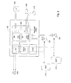
- Fig. 1 is high level block diagram of a test system in accordance with embodiments of the present disclosure.
- Fig. 2 is an illustrative diagram of a test model editor in accordance with embodiments of the present disclosure.
- Fig. 3 depict illustrative examples of test models.
- Fig. 4 is a high level work flow of processing that may be performed in accordance with aspects of the present disclosure.
- Figs. 5A, 5B , 5C, and 5D are generic representations of the data flows corresponding to processing shown in Fig. 4 .
- Figs. 6A and 6B illustrate examples of model manipulation in accordance with the present disclosure.
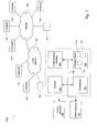
- Fig. 7 is a high level system block diagram according to an embodiment of the present disclosure.
- a test system 100 in accordance with embodiments of the present disclosure provides capability for testing a system 112.
- the system under test 112 may be any kind of system.
- An objective of testing is to gain confidence over the executability of the business processes supported by the enterprise application.
- System testing may be based, for example, on high level usage scenarios and business requirements that have been defined by business analysts or customers.
- User interface (UI) based testing is an appropriate vehicle to carry out the tests, as the system can be validated as a whole using access points that are available to the user.
- a model based testing (MBT) approach is used to define the behavior of the system under test 112 in terms of actions that change the state of the system.
- MBT model based testing
- Such an activity-based test model typically contains start and end points and a number of activities, and may be represented using a finite state machine (FSM).
- FSM finite state machine
- An activity corresponds to a step in the process that is supported by the system under test 112.
- the test system 100 may include a test environment 102 comprising tools such as a test model editor, a scenario editor, and a script recorder.
- a data store 110 may be provided to store test models and other information.
- the test model editor may provide for the creation and editing of activity-based test models, triggering test generation, and visualization of the resulting test suite.
- a test suite comprises a set of test cases that may be generated by traversing portions of the FSM that represents the test model.
- the scenario editor generates "scenarios" by assembling a sequence of captured test scripts.
- a test script is a recorded sequence of events that are generated as the user interacts with the system under test 112.
- a scenario is an assemblage of test scripts which may represent, for example, a user session.
- the scenario editor also allows the user to visualize generated executable scenarios obtained from test cases.
- the script recorder may be connected to the system under test 112 to capture and record test scripts as the user interacts with the system under test.
- the script recorder may also provide replay functionality which may be used, for example, when performing stepwise execution of a scenario.
- the test system 100 may include a proxy 104 to provide a generalized representation for test models and a generalized representation for test suites.
- the proxy 104 allows the test environment 102 to represent test models and test suites independently of their representation by the underlying components that process the test models and test suites.
- a test generator 106 may receive a generalized representation of a test model created and managed by the proxy 104 to generate a test suite irrespective of the particular representation and formatting used by the test environment 102.
- the test suite generated by the test generator 106 may likewise be managed by the proxy 104 in a generalized representation.
- An optimizer 108 may be employed to perform various optimizations; for example, to reduce the number of test cases in the test suite generated by the test generator 106 and so on.
- test generator 106 may comprise one or more specific types of test generators.
- test generator 106 may be accessed as a Web service.
- An optimizer 108 may or may not be provided for a given test generator, and may be accessed as a Web service.
- test system 100 may include functionality to assess previously generated test cases when the system under test 112 is modified, in order to identify test cases from the old system that are still applicable in the modified system. Moreover, this functionality can be implemented using existing components such as test generator 106.
- the test model editor component of the test environment 102 may include a trace analyzer 202 and a model generator 204.
- a first system under test 212 is shown.
- a corresponding test model 302 may be specified or otherwise generated by a user interacting with the system 212 within the test environment 102.
- a second system under test 214 is shown, and may represent a new version of system 212 for example.
- a corresponding "new" test model 304 may be specified or otherwise generated by the user interacting with the system 214 within the test environment 102.
- a test suite 232 generated by a suitable test generator (e.g., test generator 106, Fig. 1 ) may comprise a set of test cases based on the "old" test model 302.
- the test model editor may assess the test cases that comprise test suite 232 to determine whether any of the test cases that were generated for the old test model 302 are still valid under the new test model 304.
- the assessment involves the old and new test models 302 and 304, and the test suite 232 of test cases that were generated for the old test model 302.
- the test model editor component of the test environment 102 may include a trace analyzer 202 and a model generator 204.
- the trace analyzer 202 outputs to the model generator 204 a list 206 of "valid" test cases obtained from the list of old test cases generated from the old test model 302.
- a model 208 is generated and sent to the test generator 106.
- a result 210 is returned from the test generator 106, and depending on the result, the given test case is designated as still being a valid test case for the new test model 304 or not. Additional details of this aspect of the present disclosure are discussed below.
- a test model may be represented by a state transition diagram.
- the structural elements of test model 302 include vertices (states) A, B, and C, and edges (transitions) Trans_1, Trans_2, Trans_3, and Trans_4.
- the test model 302 also includes a constraint variable (x) which is used to constrain the traversal of the edges, and in general may comprise any number of variables from the system 212 being modeled by the test model. For example, in the test model 302, the traversal from vertex A to vertex B is permitted only when x>0. Edge traversal may also affect one or more constraint variables, as well as being affected by them. For example, the traversal from vertex B to itself along edge Trans_2 may result in incrementing the variable x.
- test models 302 and 304 will serve as illustrative examples in the discussions to follow.
- the test model 302 will be deemed to be an example of a test model for the system 212 shown in Fig. 2 , and may be referred to as the "old' test model.
- the test model 304 will be deemed to be an example of a test model for the system 214 shown in Fig. 2 , and hence may be referred to as the "new test model.
- Table I represent a test suite 232 that is generated from the old test model 302.
- the variable assignments given in the square brackets in each test case represent a test data configuration for which test execution of that test case will succeed. It will be appreciated the not all test cases are associated with a test data configuration.
- test models 302 and 304 shown in Fig. 3 will serve as a running example for the discussion of Fig. 4 .
- test model 302 is received in a step 402.
- test model 302 may be received in the trace analyzer 202 as a test model for the old system 212.
- the trace analyzer 202 may invoke the test generator 106 ( Fig. 1 ) to generate a test suite 232 comprising a plurality of test cases (e.g., Table I) for the old test model 302.
- Fig. 5A is a generic pictorial representation of the information flow involved in 402 and 404.
- the trace analyzer 202 may receive a second ("new") test model 304.
- the trace analyzer 202 may validate the structure of each test case by checking the trace information (e.g., vertices and edges) of each test case against the structure in the new test model 304. The result is a list 206 of remaining test cases from the old test suite of test cases.
- Fig. 5B is a generic pictorial representation of the information flow involved in 406 and 408.
- the vertices and edges in each test case may be compared to vertices and edges in the new test model 304. For a given test case, if the vertices in the test case are found in the new test model 304 and the edges in the test case are the same as in the new test model, then the test case is deemed to be structurally supported in the new test model.
- the edge (Trans_4) in test case (a) does not exist in the new test model. Accordingly, test case (a) is deemed structurally invalid.
- Test cases (b) and (c), on the other hand, are structurally consistent with the new test model 304.
- the vertices (A, B, and C) occur in the new test model 304.
- Test case (b) and the new test model 304 each contain an edge (Trans_1) that connects vertices A and B and an edge (Trans_3) that connects vertices B and C. Accordingly, test case (b) is deemed structurally valid.
- test case (c) contains the same vertices as in the new test model 304, namely A, B, and C.
- Test case (c) and the new test model 304 also include an edge (Trans_1) that connects vertices A and B and an edge (Trans_3) that connects vertices B and C.
- the edge in test case (c), connecting vertex B to itself, also appears in the new test model 304, namely edge Trans_2. Accordingly, test case (c) is also deemed to be structurally valid. Since the foregoing analysis is based only on structural elements (vertices and edges) of the test cases and the test model, the analysis may be implemented as a simple sequence of queries on their respective structural elements.
- the remaining test cases may then be processed in a step 410 to create corresponding "manipulated" test models.
- the trace analyzer 202 may provide the list 206 of remaining test cases to the model generator 204 to create a corresponding set of manipulated test models.
- Fig. 5C is a generic pictorial representation of the information flow involved in this step.
- the model generator 204 may process each test case in the list 206 to create a corresponding test model by using the new test model 304 as a starting point.
- the new test model 304 may be modified in accordance with the following rules so that the resulting manipulated test model represents the test sequence of the test case:
- Fig. 6A An example of the foregoing manipulations is shown in Fig. 6A for test case (b).
- the new test model 304 is shown being manipulated by eliminating an edge (Trans_2) to create manipulated test model 602. It can be seen that the resulting test model 602 represents the test sequence of test case (b).
- Fig. 6B shows another example, for test case (c).
- This test case includes an example of a test sequence that causes "unfolding" of a test path in the new test model 304 in order to create manipulated test model 604.
- processing proceeds to loop 412, where the test generator 106 is triggered (step 414) for each manipulated test model that was created in step 410. If the test case corresponding to a given manipulated test model is valid for the new test model 304, then the result 210 ( Fig. 2 ) from test generator 106 will be a test suite that is generated from the given test model. The corresponding test case is then designated, in a step 416, as being a valid test case for the new test model 304. If, on the other hand, the test generator 106 does not produce a test suite, then the corresponding test case is designated, in a step 418, as not being a valid test case for the new test model 304. For example, the result 210 from test generator 106 may be a NULL test suite, or an error code, or some other suitable negative response.
- Fig. 5D is a generic pictorial representation of the information flow involved in this step.
- step 414 when the test generator 106 is invoked for a given manipulated test model to generate a test suite, the test generator 106 will incorporate any initialization data that may be associated with the given test model. Thus, where there is initialization data, the test generator 106 will generate a test suite if the test suite can be executed with the original data configuration of the test case from which the manipulated test model was created.
- x : 8 A ⁇ Trans_ 1 ⁇ B ⁇ Trans_ 3 ⁇ C , where the data configuration sets X to 8 so that the transition (Trans_3) can occur.
- the fact that the original test case (b) for the old test model 302 allows for a data configuration of x: 6, indicates this test case is not a valid test case for the new test model 304.
- This example illustrates that multiple valid test cases may exist for a given test model.
- Fig. 7 is a block diagram of a system 700 according to some embodiments.
- the system 700 includes computers 721-723 and one or more storage systems 741 interconnected by a local network 720 such as a Local Area Network (LAN), a Wide Area Network (WAN), and the like.
- a local network 720 such as a Local Area Network (LAN), a Wide Area Network (WAN), and the like.
- the system 700 may include computers 731-734 and one or more storage systems 751 connected to the Internet 730.
- the local network 720 may be connected to the Internet 730.
- Each computer may be configured as a general purpose computing apparatus and may execute program code to perform any of the functions described herein.
- computer 721 may be a client system that hosts the test environment 102 shown in Fig. 1 .
- Another computer e.g., 722 may be a server that hosts the test generator 106.
- Each computer includes, among its components, a processor component 701 (comprising one or more processing units) operatively coupled to a communication interface 704, a data storage device 703, one or more input devices 707, one or more output devices 706, and a memory 702.
- the communication interface 704 may facilitate communication on the local network to access other systems, such as storage system 741 for example.
- Input device(s) 707 may include, for example, a keyboard, a keypad, a mouse or other pointing device, a microphone, knob or a switch, an Infra-Red (IR) port, a docking station, a touch screen, and so on. Input device(s) 707 may be used, for example, to enter information into the computer.
- Output device(s) 706 may include, for example, a display (e.g., a display screen), a speaker, a printer, and so on. Additional elements (not shown) may be including according to some embodiments.
- the data storage device 703 may comprise any appropriate persistent storage device, including combinations of magnetic storage devices (e.g., magnetic tape, hard disk drives and flash memory), optical storage devices, Read Only Memory (ROM) devices, etc., while memory 702 may comprise Random Access Memory (RAM).
- magnetic storage devices e.g., magnetic tape, hard disk drives and flash memory
- optical storage devices e.g., Read Only Memory (ROM) devices, etc.
- RAM Random Access Memory
- the data storage device 703 may store program code 712 which may be executed by the processor component 701 to cause the computer to perform any one or more of the processes and methods described herein; for example, the components of the test environment 102, or the test generator 106, and so on. Embodiments are not limited to execution of these processes by a single apparatus.
- the data storage device 703 may store data structures 714 such as object instance data, runtime objects, and any other data described herein.
- the data storage device 703 may also store data and other program code for providing additional functionality and/or which are necessary for operation thereof, such as device drivers, operating system files, etc.
- All systems and processes discussed herein may be embodied in program code stored on one or more non-transitory computer-readable media.
- Such media may include, for example, a floppy disk, a CD-ROM, a DVD-ROM, a Flash drive, magnetic tape, and solid state Random Access Memory (RAM) or Read Only Memory (ROM) storage units. It will be appreciated that embodiments are not limited to any specific combination of hardware and software.
- Elements described herein as communicating with one another are directly or indirectly capable of communicating over any number of different systems for transferring data, including but not limited to shared memory communication, a local area network, a wide area network, a telephone network, a cellular network, a fiber-optic network, a satellite network, an infrared network, a radio frequency network, and any other type of network that may be used to transmit information between devices.
- communication between systems may proceed over any one or more transmission protocols that are or become known, such as Asynchronous Transfer Mode (ATM), Internet Protocol (IP), Hypertext Transfer Protocol (HTTP) and Wireless Application Protocol (WAP).
- ATM Asynchronous Transfer Mode
- IP Internet Protocol
- HTTP Hypertext Transfer Protocol
- WAP Wireless Application Protocol
- test suites are used to compare the quality between different versions. Therefore only test cases which are not executable any more should be replaced in test suites from one version to another. This practice is preferred over the above-mentioned optimization of the test suite.
Landscapes
- Engineering & Computer Science (AREA)
- Theoretical Computer Science (AREA)
- Computer Hardware Design (AREA)
- Quality & Reliability (AREA)
- Physics & Mathematics (AREA)
- General Engineering & Computer Science (AREA)
- General Physics & Mathematics (AREA)
- Debugging And Monitoring (AREA)
Abstract
Description
- Unless otherwise indicated herein, the approaches described in this section are not prior art to the claims in this application and are not admitted to be prior art by inclusion in this section.
- Software development and testing of complex software systems may require dedicated methods to tackle special features of the software. Consider, for example, an Enterprise Resource Planning (ERP) system. Manual testing is generally not practicable to systematically test ERP systems due to the involved complexity. Accordingly, an efficient testing approach should be automatic. Model-based testing (MBT) has the potential to enable a high degree of automation in the test design.
- MBT solutions put test models into the center of the overall testing process. When the behavior changes from one system version to the other, MBT approaches change the model and re-run the automatic test generation, which often results in major changes in the test suite from version to version. Since state of the art model-based test generators optimize the test cases towards criteria like minimal number of executed test steps or minimal number of test cases, even minimal changes to the original test model can result in a completely different generated test suite.
-
Fig. 1 is high level block diagram of a test system in accordance with embodiments of the present disclosure. -
Fig. 2 is an illustrative diagram of a test model editor in accordance with embodiments of the present disclosure. -
Fig. 3 depict illustrative examples of test models. -
Fig. 4 is a high level work flow of processing that may be performed in accordance with aspects of the present disclosure. -
Figs. 5A, 5B ,5C, and 5D are generic representations of the data flows corresponding to processing shown inFig. 4 . -
Figs. 6A and6B illustrate examples of model manipulation in accordance with the present disclosure. -
Fig. 7 is a high level system block diagram according to an embodiment of the present disclosure. - In the following description, for purposes of explanation, numerous examples and specific details are set forth in order to provide a thorough understanding of the present invention. It will be evident, however, to one skilled in the art that the present invention as defined by the claims may include some or all of the features in these examples alone or in combination with other features described below, and may further include modifications and equivalents of the features and concepts described herein.
- Referring to
Fig. 1 , atest system 100 in accordance with embodiments of the present disclosure provides capability for testing asystem 112. The system undertest 112 may be any kind of system. For example, consider an enterprise application. An objective of testing is to gain confidence over the executability of the business processes supported by the enterprise application. System testing may be based, for example, on high level usage scenarios and business requirements that have been defined by business analysts or customers. User interface (UI) based testing is an appropriate vehicle to carry out the tests, as the system can be validated as a whole using access points that are available to the user. - In embodiments, a model based testing (MBT) approach is used to define the behavior of the system under
test 112 in terms of actions that change the state of the system. Such an activity-based test model typically contains start and end points and a number of activities, and may be represented using a finite state machine (FSM). An activity corresponds to a step in the process that is supported by the system undertest 112. - The
test system 100 may include atest environment 102 comprising tools such as a test model editor, a scenario editor, and a script recorder. Adata store 110 may be provided to store test models and other information. The test model editor may provide for the creation and editing of activity-based test models, triggering test generation, and visualization of the resulting test suite. A test suite comprises a set of test cases that may be generated by traversing portions of the FSM that represents the test model. The scenario editor generates "scenarios" by assembling a sequence of captured test scripts. A test script is a recorded sequence of events that are generated as the user interacts with the system undertest 112. A scenario is an assemblage of test scripts which may represent, for example, a user session. The scenario editor also allows the user to visualize generated executable scenarios obtained from test cases. The script recorder may be connected to the system undertest 112 to capture and record test scripts as the user interacts with the system under test. The script recorder may also provide replay functionality which may be used, for example, when performing stepwise execution of a scenario. - The
test system 100 may include aproxy 104 to provide a generalized representation for test models and a generalized representation for test suites. Theproxy 104 allows thetest environment 102 to represent test models and test suites independently of their representation by the underlying components that process the test models and test suites. For example, atest generator 106 may receive a generalized representation of a test model created and managed by theproxy 104 to generate a test suite irrespective of the particular representation and formatting used by thetest environment 102. The test suite generated by thetest generator 106 may likewise be managed by theproxy 104 in a generalized representation. Anoptimizer 108 may be employed to perform various optimizations; for example, to reduce the number of test cases in the test suite generated by thetest generator 106 and so on. In some embodiments, thetest generator 106 may comprise one or more specific types of test generators. In some embodiments,test generator 106 may be accessed as a Web service. Anoptimizer 108 may or may not be provided for a given test generator, and may be accessed as a Web service. - In accordance with the present disclosure,
test system 100 may include functionality to assess previously generated test cases when the system undertest 112 is modified, in order to identify test cases from the old system that are still applicable in the modified system. Moreover, this functionality can be implemented using existing components such astest generator 106. Referring toFig. 2 , in some embodiments the test model editor component of thetest environment 102 may include atrace analyzer 202 and amodel generator 204. A first system undertest 212 is shown. Acorresponding test model 302 may be specified or otherwise generated by a user interacting with thesystem 212 within thetest environment 102. A second system undertest 214 is shown, and may represent a new version ofsystem 212 for example. A corresponding "new"test model 304 may be specified or otherwise generated by the user interacting with thesystem 214 within thetest environment 102. Atest suite 232 generated by a suitable test generator (e.g.,test generator 106,Fig. 1 ) may comprise a set of test cases based on the "old"test model 302. As will be explained in more detail below, the test model editor may assess the test cases that comprisetest suite 232 to determine whether any of the test cases that were generated for theold test model 302 are still valid under thenew test model 304. In accordance with the present disclosure, the assessment involves the old andnew test models test suite 232 of test cases that were generated for theold test model 302. - As mentioned above, in some embodiments the test model editor component of the
test environment 102 may include atrace analyzer 202 and amodel generator 204. Thetrace analyzer 202 outputs to the model generator 204 alist 206 of "valid" test cases obtained from the list of old test cases generated from theold test model 302. For each given test case in thelist 206, amodel 208 is generated and sent to thetest generator 106. Aresult 210 is returned from thetest generator 106, and depending on the result, the given test case is designated as still being a valid test case for thenew test model 304 or not. Additional details of this aspect of the present disclosure are discussed below. - Referring to
Fig. 3 , a test model may be represented by a state transition diagram. Consider thetest model 302, for example. The structural elements oftest model 302 include vertices (states) A, B, and C, and edges (transitions) Trans_1, Trans_2, Trans_3, and Trans_4. Thetest model 302 also includes a constraint variable (x) which is used to constrain the traversal of the edges, and in general may comprise any number of variables from thesystem 212 being modeled by the test model. For example, in thetest model 302, the traversal from vertex A to vertex B is permitted only when x>0. Edge traversal may also affect one or more constraint variables, as well as being affected by them. For example, the traversal from vertex B to itself along edge Trans_2 may result in incrementing the variable x. - The
test models test model 302 will be deemed to be an example of a test model for thesystem 212 shown inFig. 2 , and may be referred to as the "old' test model. Likewise, thetest model 304 will be deemed to be an example of a test model for thesystem 214 shown inFig. 2 , and hence may be referred to as the "new test model. - Merely as an example, let Table I below represent a
test suite 232 that is generated from theold test model 302. The test suite in Table I comprises the following test cases:TABLE I a) [x:=0] (A) → Trans_4 → ((C)) b) [x:=6] (A) → Trans_1 → (B) → Trans-3 → ((C)) c) [x:=8] (A) → Trans_1 → (B) → Trans_2 → (B) → Trans-2 → (B) → Trans-3 → ((C)) - Referring to
Figs. 2 and4 , a process flow to assess test cases comprising a test suite in accordance with embodiments of the present disclosure is shown. Thetest models Fig. 3 will serve as a running example for the discussion ofFig. 4 . - A first ("old")
test model 302 is received in astep 402. Referring toFig. 2 , for example,test model 302 may be received in thetrace analyzer 202 as a test model for theold system 212. In astep 404, thetrace analyzer 202 may invoke the test generator 106 (Fig. 1 ) to generate atest suite 232 comprising a plurality of test cases (e.g., Table I) for theold test model 302.Fig. 5A is a generic pictorial representation of the information flow involved in 402 and 404. - In a
step 406, thetrace analyzer 202 may receive a second ("new")test model 304. In astep 408, thetrace analyzer 202 may validate the structure of each test case by checking the trace information (e.g., vertices and edges) of each test case against the structure in thenew test model 304. The result is alist 206 of remaining test cases from the old test suite of test cases.Fig. 5B is a generic pictorial representation of the information flow involved in 406 and 408. - In embodiments, for example, the vertices and edges in each test case may be compared to vertices and edges in the
new test model 304. For a given test case, if the vertices in the test case are found in thenew test model 304 and the edges in the test case are the same as in the new test model, then the test case is deemed to be structurally supported in the new test model. Consider, for example, the test cases of theold test suite 232 shown in Table I. For test case (a),
a trace analysis would reveal that test case (a) is structurally invalid. Although the same vertices (A and C) occur in thenew test model 304, the edge (Trans_4) in test case (a) does not exist in the new test model. Accordingly, test case (a) is deemed structurally invalid. - Test cases (b) and (c), on the other hand, are structurally consistent with the
new test model 304. For test case (b), the vertices (A, B, and C) occur in thenew test model 304. Test case (b) and thenew test model 304 each contain an edge (Trans_1) that connects vertices A and B and an edge (Trans_3) that connects vertices B and C. Accordingly, test case (b) is deemed structurally valid. Likewise, test case (c) contains the same vertices as in thenew test model 304, namely A, B, and C. Test case (c) and thenew test model 304 also include an edge (Trans_1) that connects vertices A and B and an edge (Trans_3) that connects vertices B and C. The edge in test case (c), connecting vertex B to itself, also appears in thenew test model 304, namely edge Trans_2. Accordingly, test case (c) is also deemed to be structurally valid. Since the foregoing analysis is based only on structural elements (vertices and edges) of the test cases and the test model, the analysis may be implemented as a simple sequence of queries on their respective structural elements. Thelist 206 of remaining test cases that are structurally valid with respect to thenew test model 304 is shown in Table II below:TABLE II a) [x:=6] (A) → Trans_1 → (B) → Trans_3 → ((C)) b) [x:=8] (A) → Trans_1 → (B) → Trans_2 → (B) → Trans_2 → (B) → Trans_3 → ((C)) - The remaining test cases may then be processed in a
step 410 to create corresponding "manipulated" test models. For example, inFig. 2 thetrace analyzer 202 may provide thelist 206 of remaining test cases to themodel generator 204 to create a corresponding set of manipulated test models.Fig. 5C is a generic pictorial representation of the information flow involved in this step. - In embodiments, the
model generator 204 may process each test case in thelist 206 to create a corresponding test model by using thenew test model 304 as a starting point. For a given test case, thenew test model 304 may be modified in accordance with the following rules so that the resulting manipulated test model represents the test sequence of the test case: - 1) Create a copy of the new test model, 304.
- 2) Remove all edges in the
new test model 304 which are not contained in the given test case. - 3) Unfold one or more test paths in the
new test model 304 by copying and inserting edges and vertices that are traversed more than once, in order to obtain the same test sequence as in the given test case. - An example of the foregoing manipulations is shown in
Fig. 6A for test case (b). Thenew test model 304 is shown being manipulated by eliminating an edge (Trans_2) to create manipulatedtest model 602. It can be seen that the resultingtest model 602 represents the test sequence of test case (b). - In some scenarios, however, a test case is not only identified by its trace, but also by its data configuration. Test case (b), for example, includes a data configuration x:=6. Accordingly, the manipulated
test model 602 may incorporate, as its initialization data, the data configuration of test case (b), which is represented by test model 602'. -
Fig. 6B shows another example, for test case (c). This test case includes an example of a test sequence that causes "unfolding" of a test path in thenew test model 304 in order to create manipulatedtest model 604. Test model 604' includes, as initialization data, the data configuration from test case (c), namely x:=8. - Continuing with
Fig. 4 , processing proceeds toloop 412, where thetest generator 106 is triggered (step 414) for each manipulated test model that was created instep 410. If the test case corresponding to a given manipulated test model is valid for thenew test model 304, then the result 210 (Fig. 2 ) fromtest generator 106 will be a test suite that is generated from the given test model. The corresponding test case is then designated, in astep 416, as being a valid test case for thenew test model 304. If, on the other hand, thetest generator 106 does not produce a test suite, then the corresponding test case is designated, in astep 418, as not being a valid test case for thenew test model 304. For example, theresult 210 fromtest generator 106 may be a NULL test suite, or an error code, or some other suitable negative response.Fig. 5D is a generic pictorial representation of the information flow involved in this step. - In embodiments of
step 414, when thetest generator 106 is invoked for a given manipulated test model to generate a test suite, thetest generator 106 will incorporate any initialization data that may be associated with the given test model. Thus, where there is initialization data, thetest generator 106 will generate a test suite if the test suite can be executed with the original data configuration of the test case from which the manipulated test model was created. - Consider, for example, test case (b). The manipulated test model 602' in
Fig. 6A corresponds to test case (b), including the initialization data derived from the data configuration of the test case, namely x:=6. Thetest generator 106 will not be able to generate a valid test case from test model 602' because the transition (Trans_3) from vertex B to C (which requires ×>7) is not permitted due to the constraint imposed by the initialization data, namely x:=6. Accordingly, test case (b), which is valid for theold test model 302, is not a valid test case for thenew test model 304. By comparison, notice that fortest model 602, where the initialization data is omitted, thetest generator 106 would produce the following test case:
where the data configuration sets X to 8 so that the transition (Trans_3) can occur. The fact that the original test case (b) for theold test model 302 allows for a data configuration of x:=6, indicates this test case is not a valid test case for thenew test model 304. - Consider the test case (c). The manipulated test model 604' in
Fig. 6B corresponds to test case (c), which includes the initialization data derived from the data configuration of the test case, namely x:=8. For test model 604', thetest generator 106 will generate a valid test case from the model because the initialization data (x:=8) allows for each of the edges, Trans_1, Trans_2, Trans_2', and Trans_3, to be generated. By comparison, note that fortest model 604, where the initialization data is omitted, thetest generator 106 would produce the following test case:
where the data configuration sets X to 6, since that is a sufficient initial condition that test execution of the test case will succeed. This example illustrates that multiple valid test cases may exist for a given test model. The test case where the data configuration is x:=6 is valid, and so is the test case where the data configuration is x:=8. -
Fig. 7 is a block diagram of asystem 700 according to some embodiments. Thesystem 700 includes computers 721-723 and one ormore storage systems 741 interconnected by alocal network 720 such as a Local Area Network (LAN), a Wide Area Network (WAN), and the like. In some embodiments, thesystem 700 may include computers 731-734 and one ormore storage systems 751 connected to theInternet 730. Thelocal network 720 may be connected to theInternet 730. - Each computer (e.g., computer 721) may be configured as a general purpose computing apparatus and may execute program code to perform any of the functions described herein. For example,
computer 721 may be a client system that hosts thetest environment 102 shown inFig. 1 . Another computer (e.g., 722) may be a server that hosts thetest generator 106. - Each computer (e.g., computer 721) includes, among its components, a processor component 701 (comprising one or more processing units) operatively coupled to a
communication interface 704, adata storage device 703, one ormore input devices 707, one ormore output devices 706, and amemory 702. Thecommunication interface 704 may facilitate communication on the local network to access other systems, such asstorage system 741 for example. - Input device(s) 707 may include, for example, a keyboard, a keypad, a mouse or other pointing device, a microphone, knob or a switch, an Infra-Red (IR) port, a docking station, a touch screen, and so on. Input device(s) 707 may be used, for example, to enter information into the computer. Output device(s) 706 may include, for example, a display (e.g., a display screen), a speaker, a printer, and so on. Additional elements (not shown) may be including according to some embodiments.
- The
data storage device 703 may comprise any appropriate persistent storage device, including combinations of magnetic storage devices (e.g., magnetic tape, hard disk drives and flash memory), optical storage devices, Read Only Memory (ROM) devices, etc., whilememory 702 may comprise Random Access Memory (RAM). - The
data storage device 703 may storeprogram code 712 which may be executed by theprocessor component 701 to cause the computer to perform any one or more of the processes and methods described herein; for example, the components of thetest environment 102, or thetest generator 106, and so on. Embodiments are not limited to execution of these processes by a single apparatus. - The
data storage device 703 may storedata structures 714 such as object instance data, runtime objects, and any other data described herein. Thedata storage device 703 may also store data and other program code for providing additional functionality and/or which are necessary for operation thereof, such as device drivers, operating system files, etc. - All systems and processes discussed herein may be embodied in program code stored on one or more non-transitory computer-readable media. Such media may include, for example, a floppy disk, a CD-ROM, a DVD-ROM, a Flash drive, magnetic tape, and solid state Random Access Memory (RAM) or Read Only Memory (ROM) storage units. It will be appreciated that embodiments are not limited to any specific combination of hardware and software. Elements described herein as communicating with one another are directly or indirectly capable of communicating over any number of different systems for transferring data, including but not limited to shared memory communication, a local area network, a wide area network, a telephone network, a cellular network, a fiber-optic network, a satellite network, an infrared network, a radio frequency network, and any other type of network that may be used to transmit information between devices. Moreover, communication between systems may proceed over any one or more transmission protocols that are or become known, such as Asynchronous Transfer Mode (ATM), Internet Protocol (IP), Hypertext Transfer Protocol (HTTP) and Wireless Application Protocol (WAP).
- The above description illustrates various embodiments of the present invention along with examples of how aspects of the present invention may be implemented. The above examples and embodiments should not be deemed to be the only embodiments, and are presented to illustrate the flexibility and advantages of the present invention as defined by the following claims. Based on the above disclosure and the following claims, other arrangements, embodiments, implementations and equivalents will be evident to those skilled in the art and may be employed without departing from the spirit and scope of the invention as defined by the claims.
- In industrial testing, test suites are used to compare the quality between different versions. Therefore only test cases which are not executable any more should be replaced in test suites from one version to another. This practice is preferred over the above-mentioned optimization of the test suite. Various solutions for computing the inclusion of a trace (test case) in a graph (test model) exist, but they all demand the provision of additional complex model transformations and tool support to the test environment. Embodiments in accordance with the present disclosure can avoid the need for such additional modeling tools, allowing for existing tools (e.g., test generator) to be used.
Claims (15)
- A computer-implemented method to validate test cases for test models comprising operating the computer system to perform steps of:receiving information for a first test model;generating first test cases from the first test model using a test generator;receiving information for a second test model;eliminating one or more test cases from among the first test cases; andfor each test case that remains among the first test cases:generating a test model corresponding to said each test case using information for the second test model; anddesignating said each test case as being valid or invalid depending on whether or not the test generator can generate a test case from the test model corresponding to said each test case.
- The method of claim 1 wherein if said each test case is associated a data constraint, then generating the corresponding test model includes incorporating the data constraint; and/or wherein the corresponding test model includes a data constraint associated with said each test case.
- The method of claim 1 or 2 wherein eliminating one or more test cases from among the first test cases includes comparing each test case with the second test model, wherein said each test case is deemed eliminated depending on the comparison.
- The method of claim 3 wherein the comparison includes comparing a structure of said each test case with a structure of the second test model.
- The method of any one of the preceding claims wherein generating a test model corresponding to said each test case includes modifying a copy of the second test model based on a structure of said each test case.
- The method of claim 5 wherein modifying a copy of the second test model includes removing elements from the copy of the second test model that are absent from said each test case.
- The method of any one of the preceding claims wherein the first test model and the second test model are state-based models.
- A system for validating test cases for test models comprising:a processor; anda data store having stored thereon executable program code configured to caused the processor to:receive information for a first test model;generate first test cases from the first test model using a test generator;receive information for a second test model;eliminate one or more test cases from among the first test cases; andfor each test case that remains among the first test cases:generate a test model corresponding to said each test case using information for the second test model; anddesignate said each test case as being valid or invalid depending on whether or not the test generator can generate a test case from the test model corresponding to said each test case.
- The system of claim 8 wherein if said each test case is associated a data constraint, then the corresponding test model incorporates the data constraint.
- The system of claim 8 or 9 wherein the one or more test cases are eliminated from among the first test cases based on a comparison of each test case with the second test model.
- The system of claim 10 wherein the comparison includes a comparison of a structure of said each test case with a structure of the second test model.
- The system of any one of claims 8 to 11 wherein the test model corresponding to said each test case is based on modifications made to the second test model based on a structure of said each test case.
- The system of claim 12 wherein modifications made to the second test model include removal of one or more structural elements from the second test model.
- The system of any one of claims 8 to 13 wherein the first test model and the second test model are state-based models.
- A non-transitory computer-readable storage medium having stored thereon computer executable program code comprising program code configured to cause a computer to perform a method according to any one of claims 1 to 7.
Applications Claiming Priority (1)
| Application Number | Priority Date | Filing Date | Title |
|---|---|---|---|
| US13/413,461 US8910123B2 (en) | 2012-03-06 | 2012-03-06 | Automated validation of generated test cases following changes to the underlying test model |
Publications (2)
| Publication Number | Publication Date |
|---|---|
| EP2637093A1 true EP2637093A1 (en) | 2013-09-11 |
| EP2637093B1 EP2637093B1 (en) | 2015-09-09 |
Family
ID=47683494
Family Applications (1)
| Application Number | Title | Priority Date | Filing Date |
|---|---|---|---|
| EP13000560.6A Active EP2637093B1 (en) | 2012-03-06 | 2013-02-04 | Automatically checking the validity of generated test cases after test-model changes |
Country Status (2)
| Country | Link |
|---|---|
| US (1) | US8910123B2 (en) |
| EP (1) | EP2637093B1 (en) |
Cited By (2)
| Publication number | Priority date | Publication date | Assignee | Title |
|---|---|---|---|---|
| CN104765683A (en) * | 2015-03-30 | 2015-07-08 | 西北工业大学 | MOEA/D algorithm based multi-target optimizing method for regression test case |
| CN109408355A (en) * | 2017-08-16 | 2019-03-01 | 迈普通信技术股份有限公司 | Test case acquisition methods and device |
Families Citing this family (11)
| Publication number | Priority date | Publication date | Assignee | Title |
|---|---|---|---|---|
| US8972785B2 (en) * | 2012-07-13 | 2015-03-03 | Freescale Semiconductor, Inc. | Classifying processor testcases |
| US10339485B2 (en) * | 2012-12-14 | 2019-07-02 | International Business Machines Corporation | Efficiently generating test cases |
| JP5894954B2 (en) * | 2013-03-22 | 2016-03-30 | 株式会社日立製作所 | Test case generation method, test case generation device, and program |
| US9304892B2 (en) | 2013-06-03 | 2016-04-05 | Sap Se | Determining behavior models |
| US9355020B2 (en) | 2014-07-22 | 2016-05-31 | Sap Se | Resolving nondeterminism in application behavior models |
| US9952965B2 (en) * | 2015-08-06 | 2018-04-24 | International Business Machines Corporation | Test self-verification with integrated transparent self-diagnose |
| US10282283B2 (en) | 2016-01-28 | 2019-05-07 | Accenture Global Solutions Limited | Orchestrating and providing a regression test |
| US10055330B2 (en) * | 2016-11-29 | 2018-08-21 | Bank Of America Corporation | Feature file validation tool |
| US20190129832A1 (en) * | 2017-11-02 | 2019-05-02 | Siemens Aktiengesellschaft | System and method for test data generation for use in model based testing using source code test annotations and constraint solving |
| CN118487980B (en) * | 2024-06-05 | 2025-01-28 | 青岛裕华电子科技有限公司 | A power communication performance evaluation system and method based on simulation model |
| WO2026052547A1 (en) * | 2024-09-06 | 2026-03-12 | Siemens Aktiengesellschaft | A method and system for validating equipment and process behavior in a technical installation |
Citations (1)
| Publication number | Priority date | Publication date | Assignee | Title |
|---|---|---|---|---|
| US20070240113A1 (en) * | 2006-01-30 | 2007-10-11 | Microsoft Corporation | Model independent input reduction |
Family Cites Families (2)
| Publication number | Priority date | Publication date | Assignee | Title |
|---|---|---|---|---|
| US6732356B1 (en) * | 2000-03-31 | 2004-05-04 | Intel Corporation | System and method of using partially resolved predicates for elimination of comparison instruction |
| US9064038B2 (en) * | 2006-08-29 | 2015-06-23 | International Business Machines Corporation | Method and system for combining multiple benchmarks |
-
2012
- 2012-03-06 US US13/413,461 patent/US8910123B2/en active Active
-
2013
- 2013-02-04 EP EP13000560.6A patent/EP2637093B1/en active Active
Patent Citations (1)
| Publication number | Priority date | Publication date | Assignee | Title |
|---|---|---|---|---|
| US20070240113A1 (en) * | 2006-01-30 | 2007-10-11 | Microsoft Corporation | Model independent input reduction |
Non-Patent Citations (2)
| Title |
|---|
| KOREL B ET AL: "Model based regression test reduction using dependence analysis", PROCEEDINGS INTERNATIONAL CONFERENCE ON SOFTWARE MAINTENANCE IEEE COMPUT. SOC. LOS ALAMITOS, CA, USA, 2002, pages 214 - 223, XP002694949, ISBN: 0-7695-1819-2 * |
| TAHAT L H ET AL: "Requirement-based automated black-box test generation", 25TH ANNUAL INTERNATIONAL COMPUTER SOFTWARE AND APPLICATIONS CONFERENCE. COMPSAC 2001 IEEE PISCATAWAY, NJ, USA, 2001, pages 489 - 495, XP002694950, ISBN: 0-7695-1372-7 * |
Cited By (4)
| Publication number | Priority date | Publication date | Assignee | Title |
|---|---|---|---|---|
| CN104765683A (en) * | 2015-03-30 | 2015-07-08 | 西北工业大学 | MOEA/D algorithm based multi-target optimizing method for regression test case |
| CN104765683B (en) * | 2015-03-30 | 2017-06-06 | 西北工业大学 | Regression test case Multipurpose Optimal Method based on MOEA/D algorithms |
| CN109408355A (en) * | 2017-08-16 | 2019-03-01 | 迈普通信技术股份有限公司 | Test case acquisition methods and device |
| CN109408355B (en) * | 2017-08-16 | 2022-02-22 | 迈普通信技术股份有限公司 | Test case obtaining method and device |
Also Published As
| Publication number | Publication date |
|---|---|
| US20130239092A1 (en) | 2013-09-12 |
| EP2637093B1 (en) | 2015-09-09 |
| US8910123B2 (en) | 2014-12-09 |
Similar Documents
| Publication | Publication Date | Title |
|---|---|---|
| EP2637093B1 (en) | Automatically checking the validity of generated test cases after test-model changes | |
| US8510720B2 (en) | System landscape trace | |
| EP3115902B1 (en) | Framework for automated testing of mobile apps | |
| US8819642B2 (en) | Method and system for generating and processing black box test cases | |
| US9063808B2 (en) | Deploying a package for a software application | |
| CN107220172B (en) | Method and system for automated User Interface (UI) testing via model-driven techniques | |
| US10733517B2 (en) | Decision service | |
| Méndez-Porras et al. | Automated Testing of Mobile Applications: A Systematic Map and Review. | |
| US8627337B2 (en) | Programmatic modification of a message flow during runtime | |
| WO2014145818A1 (en) | A graphic user interface based network management system to define and execute troubleshooting procedure | |
| US8850407B2 (en) | Test script generation | |
| US20190129832A1 (en) | System and method for test data generation for use in model based testing using source code test annotations and constraint solving | |
| US20120204149A1 (en) | Discovery-based migration correctness testing | |
| JP2020505710A (en) | Methods and systems for verifying software programs | |
| US20050203717A1 (en) | Automated testing system, method and program product using testing map | |
| CN117707944A (en) | Method, system, equipment and medium for testing compatibility of credit-invasive application software | |
| CN104471530A (en) | Executable software specification generation | |
| US9515912B1 (en) | Decomposing application topology data into transaction tracking data | |
| US10025697B2 (en) | Generation of automated unit tests for a controller layer system and method | |
| US10204134B2 (en) | Automatic detection of problems in a large-scale multi-record update system and method | |
| US20090164978A1 (en) | Method and system for providing post-mortem service level debugging | |
| CN103714066B (en) | Template-based database analyzer | |
| Aslam | Deriving behavioral specifications of industrial software components | |
| CN110795338B (en) | Front-end and back-end interaction-based automatic testing method and device and electronic equipment | |
| US12517810B2 (en) | Reverse testing strategies designed for black-box and exploratory testing |
Legal Events
| Date | Code | Title | Description |
|---|---|---|---|
| PUAI | Public reference made under article 153(3) epc to a published international application that has entered the european phase |
Free format text: ORIGINAL CODE: 0009012 |
|
| AK | Designated contracting states |
Kind code of ref document: A1 Designated state(s): AL AT BE BG CH CY CZ DE DK EE ES FI FR GB GR HR HU IE IS IT LI LT LU LV MC MK MT NL NO PL PT RO RS SE SI SK SM TR |
|
| AX | Request for extension of the european patent |
Extension state: BA ME |
|
| 17P | Request for examination filed |
Effective date: 20140311 |
|
| RBV | Designated contracting states (corrected) |
Designated state(s): AL AT BE BG CH CY CZ DE DK EE ES FI FR GB GR HR HU IE IS IT LI LT LU LV MC MK MT NL NO PL PT RO RS SE SI SK SM TR |
|
| 17Q | First examination report despatched |
Effective date: 20140516 |
|
| RAP1 | Party data changed (applicant data changed or rights of an application transferred) |
Owner name: SAP SE |
|
| GRAP | Despatch of communication of intention to grant a patent |
Free format text: ORIGINAL CODE: EPIDOSNIGR1 |
|
| INTG | Intention to grant announced |
Effective date: 20150414 |
|
| INTG | Intention to grant announced |
Effective date: 20150416 |
|
| GRAS | Grant fee paid |
Free format text: ORIGINAL CODE: EPIDOSNIGR3 |
|
| GRAA | (expected) grant |
Free format text: ORIGINAL CODE: 0009210 |
|
| AK | Designated contracting states |
Kind code of ref document: B1 Designated state(s): AL AT BE BG CH CY CZ DE DK EE ES FI FR GB GR HR HU IE IS IT LI LT LU LV MC MK MT NL NO PL PT RO RS SE SI SK SM TR |
|
| REG | Reference to a national code |
Ref country code: GB Ref legal event code: FG4D |
|
| REG | Reference to a national code |
Ref country code: AT Ref legal event code: REF Ref document number: 748636 Country of ref document: AT Kind code of ref document: T Effective date: 20150915 Ref country code: CH Ref legal event code: EP |
|
| REG | Reference to a national code |
Ref country code: IE Ref legal event code: FG4D |
|
| REG | Reference to a national code |
Ref country code: DE Ref legal event code: R096 Ref document number: 602013002860 Country of ref document: DE |
|
| REG | Reference to a national code |
Ref country code: NL Ref legal event code: MP Effective date: 20150909 |
|
| REG | Reference to a national code |
Ref country code: FR Ref legal event code: PLFP Year of fee payment: 4 |
|
| PG25 | Lapsed in a contracting state [announced via postgrant information from national office to epo] |
Ref country code: NO Free format text: LAPSE BECAUSE OF FAILURE TO SUBMIT A TRANSLATION OF THE DESCRIPTION OR TO PAY THE FEE WITHIN THE PRESCRIBED TIME-LIMIT Effective date: 20151209 Ref country code: LT Free format text: LAPSE BECAUSE OF FAILURE TO SUBMIT A TRANSLATION OF THE DESCRIPTION OR TO PAY THE FEE WITHIN THE PRESCRIBED TIME-LIMIT Effective date: 20150909 Ref country code: LV Free format text: LAPSE BECAUSE OF FAILURE TO SUBMIT A TRANSLATION OF THE DESCRIPTION OR TO PAY THE FEE WITHIN THE PRESCRIBED TIME-LIMIT Effective date: 20150909 Ref country code: FI Free format text: LAPSE BECAUSE OF FAILURE TO SUBMIT A TRANSLATION OF THE DESCRIPTION OR TO PAY THE FEE WITHIN THE PRESCRIBED TIME-LIMIT Effective date: 20150909 Ref country code: GR Free format text: LAPSE BECAUSE OF FAILURE TO SUBMIT A TRANSLATION OF THE DESCRIPTION OR TO PAY THE FEE WITHIN THE PRESCRIBED TIME-LIMIT Effective date: 20151210 |
|
| REG | Reference to a national code |
Ref country code: LT Ref legal event code: MG4D |
|
| REG | Reference to a national code |
Ref country code: AT Ref legal event code: MK05 Ref document number: 748636 Country of ref document: AT Kind code of ref document: T Effective date: 20150909 |
|
| PG25 | Lapsed in a contracting state [announced via postgrant information from national office to epo] |
Ref country code: RS Free format text: LAPSE BECAUSE OF FAILURE TO SUBMIT A TRANSLATION OF THE DESCRIPTION OR TO PAY THE FEE WITHIN THE PRESCRIBED TIME-LIMIT Effective date: 20150909 Ref country code: HR Free format text: LAPSE BECAUSE OF FAILURE TO SUBMIT A TRANSLATION OF THE DESCRIPTION OR TO PAY THE FEE WITHIN THE PRESCRIBED TIME-LIMIT Effective date: 20150909 Ref country code: ES Free format text: LAPSE BECAUSE OF FAILURE TO SUBMIT A TRANSLATION OF THE DESCRIPTION OR TO PAY THE FEE WITHIN THE PRESCRIBED TIME-LIMIT Effective date: 20150909 Ref country code: SE Free format text: LAPSE BECAUSE OF FAILURE TO SUBMIT A TRANSLATION OF THE DESCRIPTION OR TO PAY THE FEE WITHIN THE PRESCRIBED TIME-LIMIT Effective date: 20150909 |
|
| PG25 | Lapsed in a contracting state [announced via postgrant information from national office to epo] |
Ref country code: NL Free format text: LAPSE BECAUSE OF FAILURE TO SUBMIT A TRANSLATION OF THE DESCRIPTION OR TO PAY THE FEE WITHIN THE PRESCRIBED TIME-LIMIT Effective date: 20150909 |
|
| PG25 | Lapsed in a contracting state [announced via postgrant information from national office to epo] |
Ref country code: SK Free format text: LAPSE BECAUSE OF FAILURE TO SUBMIT A TRANSLATION OF THE DESCRIPTION OR TO PAY THE FEE WITHIN THE PRESCRIBED TIME-LIMIT Effective date: 20150909 Ref country code: EE Free format text: LAPSE BECAUSE OF FAILURE TO SUBMIT A TRANSLATION OF THE DESCRIPTION OR TO PAY THE FEE WITHIN THE PRESCRIBED TIME-LIMIT Effective date: 20150909 Ref country code: IS Free format text: LAPSE BECAUSE OF FAILURE TO SUBMIT A TRANSLATION OF THE DESCRIPTION OR TO PAY THE FEE WITHIN THE PRESCRIBED TIME-LIMIT Effective date: 20160109 Ref country code: IT Free format text: LAPSE BECAUSE OF FAILURE TO SUBMIT A TRANSLATION OF THE DESCRIPTION OR TO PAY THE FEE WITHIN THE PRESCRIBED TIME-LIMIT Effective date: 20150909 Ref country code: CZ Free format text: LAPSE BECAUSE OF FAILURE TO SUBMIT A TRANSLATION OF THE DESCRIPTION OR TO PAY THE FEE WITHIN THE PRESCRIBED TIME-LIMIT Effective date: 20150909 |
|
| PG25 | Lapsed in a contracting state [announced via postgrant information from national office to epo] |
Ref country code: AT Free format text: LAPSE BECAUSE OF FAILURE TO SUBMIT A TRANSLATION OF THE DESCRIPTION OR TO PAY THE FEE WITHIN THE PRESCRIBED TIME-LIMIT Effective date: 20150909 Ref country code: RO Free format text: LAPSE BECAUSE OF FAILURE TO SUBMIT A TRANSLATION OF THE DESCRIPTION OR TO PAY THE FEE WITHIN THE PRESCRIBED TIME-LIMIT Effective date: 20150909 Ref country code: PL Free format text: LAPSE BECAUSE OF FAILURE TO SUBMIT A TRANSLATION OF THE DESCRIPTION OR TO PAY THE FEE WITHIN THE PRESCRIBED TIME-LIMIT Effective date: 20150909 Ref country code: BE Free format text: LAPSE BECAUSE OF NON-PAYMENT OF DUE FEES Effective date: 20160229 Ref country code: PT Free format text: LAPSE BECAUSE OF FAILURE TO SUBMIT A TRANSLATION OF THE DESCRIPTION OR TO PAY THE FEE WITHIN THE PRESCRIBED TIME-LIMIT Effective date: 20160111 |
|
| REG | Reference to a national code |
Ref country code: DE Ref legal event code: R097 Ref document number: 602013002860 Country of ref document: DE |
|
| PLBE | No opposition filed within time limit |
Free format text: ORIGINAL CODE: 0009261 |
|
| STAA | Information on the status of an ep patent application or granted ep patent |
Free format text: STATUS: NO OPPOSITION FILED WITHIN TIME LIMIT |
|
| 26N | No opposition filed |
Effective date: 20160610 |
|
| PG25 | Lapsed in a contracting state [announced via postgrant information from national office to epo] |
Ref country code: SI Free format text: LAPSE BECAUSE OF FAILURE TO SUBMIT A TRANSLATION OF THE DESCRIPTION OR TO PAY THE FEE WITHIN THE PRESCRIBED TIME-LIMIT Effective date: 20150909 Ref country code: DK Free format text: LAPSE BECAUSE OF FAILURE TO SUBMIT A TRANSLATION OF THE DESCRIPTION OR TO PAY THE FEE WITHIN THE PRESCRIBED TIME-LIMIT Effective date: 20150909 |
|
| PG25 | Lapsed in a contracting state [announced via postgrant information from national office to epo] |
Ref country code: LU Free format text: LAPSE BECAUSE OF FAILURE TO SUBMIT A TRANSLATION OF THE DESCRIPTION OR TO PAY THE FEE WITHIN THE PRESCRIBED TIME-LIMIT Effective date: 20160204 Ref country code: MC Free format text: LAPSE BECAUSE OF FAILURE TO SUBMIT A TRANSLATION OF THE DESCRIPTION OR TO PAY THE FEE WITHIN THE PRESCRIBED TIME-LIMIT Effective date: 20150909 |
|
| REG | Reference to a national code |
Ref country code: CH Ref legal event code: PL |
|
| PG25 | Lapsed in a contracting state [announced via postgrant information from national office to epo] |
Ref country code: LI Free format text: LAPSE BECAUSE OF NON-PAYMENT OF DUE FEES Effective date: 20160229 Ref country code: CH Free format text: LAPSE BECAUSE OF NON-PAYMENT OF DUE FEES Effective date: 20160229 |
|
| REG | Reference to a national code |
Ref country code: IE Ref legal event code: MM4A |
|
| PG25 | Lapsed in a contracting state [announced via postgrant information from national office to epo] |
Ref country code: BE Free format text: LAPSE BECAUSE OF FAILURE TO SUBMIT A TRANSLATION OF THE DESCRIPTION OR TO PAY THE FEE WITHIN THE PRESCRIBED TIME-LIMIT Effective date: 20150909 |
|
| PG25 | Lapsed in a contracting state [announced via postgrant information from national office to epo] |
Ref country code: IE Free format text: LAPSE BECAUSE OF NON-PAYMENT OF DUE FEES Effective date: 20160204 |
|
| REG | Reference to a national code |
Ref country code: FR Ref legal event code: PLFP Year of fee payment: 5 |
|
| PG25 | Lapsed in a contracting state [announced via postgrant information from national office to epo] |
Ref country code: MT Free format text: LAPSE BECAUSE OF FAILURE TO SUBMIT A TRANSLATION OF THE DESCRIPTION OR TO PAY THE FEE WITHIN THE PRESCRIBED TIME-LIMIT Effective date: 20150909 |
|
| REG | Reference to a national code |
Ref country code: FR Ref legal event code: PLFP Year of fee payment: 6 |
|
| PG25 | Lapsed in a contracting state [announced via postgrant information from national office to epo] |
Ref country code: SM Free format text: LAPSE BECAUSE OF FAILURE TO SUBMIT A TRANSLATION OF THE DESCRIPTION OR TO PAY THE FEE WITHIN THE PRESCRIBED TIME-LIMIT Effective date: 20150909 Ref country code: HU Free format text: LAPSE BECAUSE OF FAILURE TO SUBMIT A TRANSLATION OF THE DESCRIPTION OR TO PAY THE FEE WITHIN THE PRESCRIBED TIME-LIMIT; INVALID AB INITIO Effective date: 20130204 Ref country code: CY Free format text: LAPSE BECAUSE OF FAILURE TO SUBMIT A TRANSLATION OF THE DESCRIPTION OR TO PAY THE FEE WITHIN THE PRESCRIBED TIME-LIMIT Effective date: 20150909 |
|
| PG25 | Lapsed in a contracting state [announced via postgrant information from national office to epo] |
Ref country code: MK Free format text: LAPSE BECAUSE OF FAILURE TO SUBMIT A TRANSLATION OF THE DESCRIPTION OR TO PAY THE FEE WITHIN THE PRESCRIBED TIME-LIMIT Effective date: 20150909 Ref country code: MT Free format text: LAPSE BECAUSE OF FAILURE TO SUBMIT A TRANSLATION OF THE DESCRIPTION OR TO PAY THE FEE WITHIN THE PRESCRIBED TIME-LIMIT Effective date: 20160229 Ref country code: TR Free format text: LAPSE BECAUSE OF FAILURE TO SUBMIT A TRANSLATION OF THE DESCRIPTION OR TO PAY THE FEE WITHIN THE PRESCRIBED TIME-LIMIT Effective date: 20150909 |
|
| PG25 | Lapsed in a contracting state [announced via postgrant information from national office to epo] |
Ref country code: BG Free format text: LAPSE BECAUSE OF FAILURE TO SUBMIT A TRANSLATION OF THE DESCRIPTION OR TO PAY THE FEE WITHIN THE PRESCRIBED TIME-LIMIT Effective date: 20150909 |
|
| PG25 | Lapsed in a contracting state [announced via postgrant information from national office to epo] |
Ref country code: AL Free format text: LAPSE BECAUSE OF FAILURE TO SUBMIT A TRANSLATION OF THE DESCRIPTION OR TO PAY THE FEE WITHIN THE PRESCRIBED TIME-LIMIT Effective date: 20150909 |
|
| PGFP | Annual fee paid to national office [announced via postgrant information from national office to epo] |
Ref country code: GB Payment date: 20260219 Year of fee payment: 14 |
|
| PGFP | Annual fee paid to national office [announced via postgrant information from national office to epo] |
Ref country code: DE Payment date: 20260218 Year of fee payment: 14 |
|
| PGFP | Annual fee paid to national office [announced via postgrant information from national office to epo] |
Ref country code: FR Payment date: 20260218 Year of fee payment: 14 |