EP2636968A1 - Storage container and method for fitting a storage container - Google Patents
Storage container and method for fitting a storage container Download PDFInfo
- Publication number
- EP2636968A1 EP2636968A1 EP12158463.5A EP12158463A EP2636968A1 EP 2636968 A1 EP2636968 A1 EP 2636968A1 EP 12158463 A EP12158463 A EP 12158463A EP 2636968 A1 EP2636968 A1 EP 2636968A1
- Authority
- EP
- European Patent Office
- Prior art keywords
- container
- storage container
- inner lid
- inner container
- lid
- Prior art date
- Legal status (The legal status is an assumption and is not a legal conclusion. Google has not performed a legal analysis and makes no representation as to the accuracy of the status listed.)
- Granted
Links
Images


Classifications
-
- F—MECHANICAL ENGINEERING; LIGHTING; HEATING; WEAPONS; BLASTING
- F24—HEATING; RANGES; VENTILATING
- F24H—FLUID HEATERS, e.g. WATER OR AIR HEATERS, HAVING HEAT-GENERATING MEANS, e.g. HEAT PUMPS, IN GENERAL
- F24H1/00—Water heaters, e.g. boilers, continuous-flow heaters or water-storage heaters
- F24H1/18—Water-storage heaters
- F24H1/181—Construction of the tank
- F24H1/182—Insulation
Definitions
- the invention relates to a storage container for at least one fluid medium and a method for mounting such a storage container.
- Fluid medium means in the context of the invention, in particular water and especially heating water or heated heating water or drinking water or heated drinking water.
- Storage container of the aforementioned type are known from practice in various embodiments. However, many of these known storage containers leave something to be desired in terms of their properties. Thus, the thermal insulation of the container is often unsatisfactory and the resistance of the container to mechanical influences is in need of improvement. When storage containers are transported as a whole to their site, the transport is often complicated and difficult due to the high volume. There are also known storage containers that are mounted at their site. The installation of these storage containers on site from their components is complicated and expensive.
- the invention is based on the technical problem to provide a storage container of the type mentioned above, which has excellent thermal insulation and at the same time optimal mechanical resistance and can be mounted on the site in a simple and inexpensive manner.
- the invention teaches a storage container for at least one fluid medium, with an inner container - in particular of plastic - for receiving the fluid medium, wherein at the upper end and / or lower end of the inner container at least a pipe for the loading and / or unloading of the storage container or the inner container is connected to the fluid medium, wherein at the lower front end of the inner container serving as an inner container foot lower inner lid is placed and wherein at the upper end face of the inner container, an upper inner lid is placed, wherein a the inner container and the lower inner lid - preferably also the upper inner lid - surrounding outer Dämmmantel (outer container) is provided and wherein the outer Dämmmantel has a plurality in the longitudinal direction of the storage container adjacent to each other or stacked Dämmsegmente.
- the inner container or the wall of the inner container is preferably made of a fiber-reinforced plastic or substantially of a fiber-reinforced plastic. It is within the scope of the invention that the inner container is cylindrical and recommended has rounded ends. - The inner lid placed on the inner lid serve to protect the connected to the inner container lines against transport damage and the like. On the other hand, they should limit the frontal heat losses of the storage container.
- the lower inner lid serves as a container foot or as a foot of the inner container and is in the mounted state of the storage container on a base or on the ground. Conveniently, the upper inner lid and / or the lower inner lid is cylindrical or substantially cylindrical.
- the outer diameter of the inner container and the inner lid is preferably 600 to 700 mm and in particular 670 mm. These Dimensions make it easy to handle in the door area of buildings.
- a distributor device is connected to the inner container via a plurality of lines at the upper end face and / or at the lower front end of the inner container.
- the upper inner lid and / or the lower inner lid then serves to protect this plurality of lines.
- a distributor device protrudes from the lateral surface of the associated inner lid.
- a distribution device arranged on the side surface of an inner cover or projecting out of the lateral surface or on the lateral surface of the inner cover arranged line ends or projecting from the side surface of the line ends simplified referred to as a line connection element.
- a very preferred embodiment of the invention is characterized in that the two inner covers are fixed by means of at least one bandage element, preferably with several bandage elements on the inner container, wherein a bandage element overlaps each of the two inner lid and is guided along the outside of the inner container in the longitudinal direction of the inner container ,
- a bandage element is preferably a tensioning element or a tensioning band that is prestressed in the mounted state. It is recommended that the inner lid have grooves for the bandage elements.
- a recommended embodiment of the invention is characterized in that the upper inner lid and / or the lower inner lid of a polymer foam or substantially consists of a polymer foam / consist, wherein the polymer foam is preferably foamed or expanded polystyrene (EPS) is.
- the polymer foam or the expanded polystyrene (EPS) has a density or foam density of 30 to 45 kg / m 3 , preferably from 32 to 40 kg / m 3 .
- the invention is based on the finding that it is expedient if the polymer foam of the inner lid has a relatively high density or foam density, because the inner lid should protect the front ends or the lines of the inner container from damage during transport.
- the material or the polymer foam of the inner cover expediently has a thermal conductivity of 0.025 to 0.030 W / mK and preferably a thermal conductivity of 0.026 to 0.029 W / mK.
- an inner cover or each inner lid has an inner container-side recess for receiving the at least one line connected to the associated front end of the inner container. It is within the scope of the invention that a plurality of lines connected to a front end of the inner container are received in the recess of the associated inner lid. Conveniently, the recess is arranged centrally or centrally in the associated inner lid. It is furthermore within the scope of the invention that an inner cover has at least one lateral connection opening for a line connection element.
- the line connection element means, in particular, a line end or several line ends or a distribution device connected to the associated front end of the inner container via a plurality of lines.
- At least one line connection element protrudes from the lateral surface of the upper inner cover and / or the lower inner cover.
- the term pipe connection element has already been defined above.
- an inner lid is cylindrical and the lateral surface of the inner lid forms the cylinder jacket.
- an insulating segment forming an outer container foot is pushed onto the inner container or onto the lower inner lid and that this outer container base surrounds the lower inner lid forming the inner container foot at least over part of its height or vertical height.
- the outer container foot surrounds the inner container foot over its entire height or vertical height.
- the outer container foot expediently rests on a base or on the ground / ground. It is recommended that the bottom of the outer container foot is aligned with the underside of the inner container foot.
- At least one further insulating segment is formed on the lower insulating segment forming the outer container foot is pushed, which surrounds at least the inner container or a portion of the inner container and preferably surrounds positively.
- two or at least two further insulating segments are pushed onto the outer container foot, which completely surrounds the inner container or surround it completely in a form-fitting manner.
- Empfohlene encouraged the unit from the inner container and the two inner lids is cylindrical and the Dämmsegmente of the outer Dämmmantels each have adapted to the diameter of this unit cylindrical recess, preferably central cylindrical recess, so that a Dämmsegment positively pushed onto the unit of inner container and inner lid is.
- a slight clearance between an insulating segment and the inner container or an inner lid may be provided, so that the Dämmsegmente are easily pushed onto the cylindrical unit.
- the insulating segments forming the outer insulating jacket in the assembled state close to one another in a form-fitting manner. This means that a bottom of a Dämmsegmentes positively connects to the surface of the underlying Dämmsegmentes.
- a particularly preferred embodiment of the invention is characterized in that the Dämmsegmente of the outer Dämmmantels each having an inner container side channel which extends over the height of a Dämmsegmentes and is adapted to the at least one of the upper inner lid laterally projecting line connection element, so that the Dämmsegmente from the top are easily slid over the upper inner lid.
- the insulating segments of the outer Dämmmantels are rectangular in cross-section or substantially rectangular in shape and the inner container side channel for the at least one line connection element of the upper inner lid is then preferably arranged at a corner of the rectangle.
- the Dämmsegmente square The corners of the rectangle or square are preferably rounded.
- an upper insulating segment is mounted on the unit of inner container and inner lids or on the upper inner lid, this upper Dämmsegment is advantageously mounted in the form of at least two Dämmsegment suppose, preferably from the sides or from opposite sides the unit or pushed to the upper inner lid. Empfohlene honored this upper Dämmsegment is therefore not pushed from above the unit or on the upper inner lid.
- This upper Dämmsegment as it forms an outer cover of the storage container according to the invention.
- the upper Dämmsegment an upper insulating layer, which covers the top of the upper inner lid.
- the insulating segments of the outer Dämmmantels or at least the surrounding the inner container Dämmsegmente consist of a polymer foam or substantially of a polymer foam, wherein the polymer foam is preferably foamed or expanded polystyrene (EPS).
- EPS expanded polystyrene
- this polymer foam or the expanded polystyrene (EPS) has a density or foam density of 25 to 35 kg / m 3 , particularly preferably from 27 to 33 kg / m 3 .
- the polymer foam of the insulating segments have a lower density or foam density than the polymer foam from which the inner covers are made. It is within the scope of the invention that the insulating segments or the outer Dämmmantel serves primarily the thermal insulation.
- the polymer foam of the Dämmsegmente graphite is attached.
- the thermal conductivity of the insulating segments is suitably 0.25 to 0.30 W / mK and preferably 0.26 to 0.29 W / mK.
- the invention also provides a method for mounting a storage container according to the invention, wherein the Dämmsegmente forming the outer Dämmmantelbe pushed from above onto the assembly of inner container and inner covers, wherein at least one outstanding from the upper inner lid line connection element when sliding over a Dämmsegmentes on the upper inner lid in encloses an inner container side channel of the Dämmsegmentes and preferably this Dämmsegment is then rotated by an angle in the desired orientation about the inner container or to the aggregate of inner container and inner covers.
- the angle is for example 45 °.
- the aggregate of inner container with the attached inner caps and the Dämmsegmente for the outer Dämmmantel is transported separately to the installation and only on site the Dämmsegmente be attached to the unit or pushed onto the unit of inner container and inner caps ,
- the assembly of inner container and inner caps has an oval cross-section.
- the insulating segments of the outer Dämmmantels are expediently formed at least two parts and the parts of a Dämmsegmentes are preferably pushed from the side onto the inner container or on the inner lid.
- the invention is based on the finding that with the storage container according to the invention, a plurality of advantages are achieved, which in many known from practice storage containers are not available.
- the storage container according to the invention is characterized by excellent thermal insulation and also has both the assembly of inner container and inner covers and the entire storage tank optimal resistance or resistance to mechanical influences.
- the storage container or the components of the storage container can be easily transported to the installation site.
- the components of the storage container can be mounted in an uncomplicated way or connect to each other.
- the storage container according to the invention is characterized by relatively low costs. Incidentally, the assembled storage container has optimum strength or stability, even at relatively high volumes of, for example, 500 l.
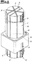
- the figures relate to a storage container 1 for a fluid medium with an inner container 2 made of plastic for receiving the fluid medium.
- an inner container 2 made of plastic for receiving the fluid medium.
- the pipelines 5 at the upper front end 3 and at the lower front end 4 are in each case connected to a line connection element in the form of a distributor device 12.
- Fig. 3 It can be seen that at the lower front end 4 of the inner container 2 serving as an inner Be Strukturerfuß lower inner lid 6 is placed and that at the upper end face 3 of the inner container 2, an upper inner lid 7 is placed.
- the wall of the inner container is preferably made of fiber-reinforced plastic and the inner lid 6, 7 are preferably made of foamed polystyrene (EPS).
- EPS foamed polystyrene
- the two inner lids 6, 7 are fixed to the inner container 2 by means of banding elements 8 formed in the form of tension bands 8.
- each clamping band 8 overlaps each of the two inner covers 6, 7 and is guided along the outside of the inner container 2 in the longitudinal direction of the inner container 2.
- the Inner lid 6, 7 grooves 9 for receiving the tension bands 8 on.
- the Fig. 3 further shows that preferred and in the embodiment, the unit from the inner container 2 and the two inner caps 6, 7 is cylindrical.
- Fig. 2 is an inner lid 6, 7 shown in perspective. It is within the scope of the invention that both the lower inner lid 6 and the upper inner lid 7 in the in Fig. 2 illustrated manner are formed and thus identical or substantially identical.
- the two inner covers 6, 7 each have an inner container-side recess 10 for receiving the pipes 5 connected to the associated front end 3, 4 of the inner container 2. Appropriately, and in the embodiment, this recess 10 is arranged centrally in the inner lid 6, 7. Otherwise, the inner covers 6, 7 preferably and in the exemplary embodiment have a lateral connection opening 11 for the pipes 5 or for the distributor device 12 connected to the pipes 5.
- the remaining areas of the inner covers 6, 7 are preferably concave and in the exemplary embodiment, so that the inner lid can each be positively placed on the convex front end 3, 4 of the inner container 2.
- the Fig. 3 can be removed that protrudes from the lateral surface of the upper inner lid 7 and the lower inner lid 6 and at the respective lateral connection opening 11 of the inner lid 6, 7, a line connection element in the form of a distribution device 12.
- an aggregate of inner container 2 and inner covers 6, 7 surrounding outer Dämmmantel 13 is provided.
- the outer Dämmmantel 13 consists of several in the longitudinal direction of the storage container 1 adjacent to each other or stacked Dämmsegmenten 14.
- Empfohlene withdraw the Dämmsegmente 14 made of foamed Polystyrene (EPS) or essentially of foamed polystyrene (EPS), wherein the polystyrene is preferably added graphite.
- EPS foamed Polystyrene
- EPS foamed polystyrene
- the Dämmsegmente 14 each have a central cylindrical recess 15, said cylindrical recess 15 is adapted to the outer diameter of the unit from the inner container 2 and inner covers 6, 7, so that the Dämmsegmente 14 are easily pushed from above the unit can ( Fig. 4 to 7 ).
- the Dämmsegmente 14 are otherwise preferred and square in cross-section in the embodiment, the corners of the square are rounded.
- Fig. 4 shows the application of a lower Dämmsegmentes 14, which forms an outer container foot 16 of the storage container 1.
- this lower Dämmsegment 14 on a downwardly open receiving opening 17, so that the lower Dämmsegment 14 can be easily pushed over the connected to the lower inner lid 6 distribution device 12.
- the lower Dämmsegment 14 forming the outer Be diligenterfuß 16 rests on the ground and the underside of this outer container leg 16 is aligned with the underside of the inner container foot forming lower inner lid 6.
- the lower or the three lower Dämmsegmente 14 each at a corner of the square on an inner container side channel 18, so that the respective Dämmsegment 14 can be passed to the connected to the upper inner cover 7 distributor device 12 by the inner container side channel 18, the distributor device 12 when pushing the Dämmsegmentes 14 overlaps (see in particular upper Insulating segment 14 in Fig. 5 ).
- the individual insulating segments 14 are preferably superimposed in a form-fitting manner in the exemplary embodiment (FIG. Fig. 7 ).
- Fig. 6 shows that the outer cover of the storage container 1 forming upper Dämmsegment 14 of two Dämmsegment hope or half shells 19, 20 is assembled.
- the two half-shells 19, 20 are mounted from opposite sides of the storage container 1 ago. This installation variant is particularly advantageous if the installation takes place in low rooms.
Abstract
Description
Die Erfindung betrifft einen Speicherbehälter für zumindest ein fluides Medium sowie ein Verfahren zum Montieren eines solchen Speicherbehälters. - Fluides Medium meint im Rahmen der Erfindung insbesondere Wasser und vor allem Heizungswasser bzw. erwärmtes Heizungswasser oder Trinkwasser bzw. erwärmtes Trinkwasser.The invention relates to a storage container for at least one fluid medium and a method for mounting such a storage container. - Fluid medium means in the context of the invention, in particular water and especially heating water or heated heating water or drinking water or heated drinking water.
Speicherbehälter der vorstehend genannten Art sind aus der Praxis in unterschiedlichsten Ausführungsformen bekannt. Viele dieser bekannten Speicherbehälter lassen aber im Hinblick auf ihre Eigenschaften zu wünschen übrig. So ist die Wärmedämmung der Behälter oftmals nicht zufriedenstellend und auch die Resistenz der Behälter gegenüber mechanischen Einflüssen ist verbesserungsbedürftig. Wenn Speicherbehälter als Ganzes zu ihrem Aufstellungsort transportiert werden, ist der Transport aufgrund des hohen Volumens oftmals aufwendig und schwierig. Es sind auch Speicherbehälter bekannt, die an ihrem Aufstellungsort montiert werden. Die Montage dieser Speicherbehälter vor Ort aus ihren Komponenten ist aber kompliziert und aufwendig.Storage container of the aforementioned type are known from practice in various embodiments. However, many of these known storage containers leave something to be desired in terms of their properties. Thus, the thermal insulation of the container is often unsatisfactory and the resistance of the container to mechanical influences is in need of improvement. When storage containers are transported as a whole to their site, the transport is often complicated and difficult due to the high volume. There are also known storage containers that are mounted at their site. The installation of these storage containers on site from their components is complicated and expensive.
Der Erfindung liegt das technische Problem zugrunde, einen Speicherbehälter der eingangs genannten Art anzugeben, der eine hervorragende Wärmedämmung aufweist und zugleich eine optimale mechanische Resistenz und der auf einfache und wenig aufwendige Weise am Aufstellungsort montiert werden kann.The invention is based on the technical problem to provide a storage container of the type mentioned above, which has excellent thermal insulation and at the same time optimal mechanical resistance and can be mounted on the site in a simple and inexpensive manner.
Zur Lösung dieses technischen Problems lehrt die Erfindung einen Speicherbehälter für zumindest ein fluides Medium, mit einem Innenbehälter - insbesondere aus Kunststoff - für die Aufnahme des fluiden Mediums, wobei am oberen Stirnende und/oder am unteren Stirnende des Innenbehälters zumindest eine Leitung bzw. Rohrleitung für das Beladen und/oder Entladen des Speicherbehälters bzw. des Innenbehälters mit dem fluiden Medium angeschlossen ist,
wobei am unteren Stirnende des Innenbehälters ein als innerer Behälterfuß dienender unterer Innendeckel aufgesetzt ist und wobei am oberen Stirnende des Innenbehälters ein oberer Innendeckel aufgesetzt ist,
wobei ein den Innenbehälter und den unteren Innendeckel - vorzugsweise auch den oberen Innendeckel - umgebender äußerer Dämmmantel (Außenbehälter) vorgesehen ist und wobei der äußere Dämmmantel mehrere in Längsrichtung des Speicherbehälters aneinander angrenzende bzw. aufeinandergesetzte Dämmsegmente aufweist.To solve this technical problem, the invention teaches a storage container for at least one fluid medium, with an inner container - in particular of plastic - for receiving the fluid medium, wherein at the upper end and / or lower end of the inner container at least a pipe for the loading and / or unloading of the storage container or the inner container is connected to the fluid medium,
wherein at the lower front end of the inner container serving as an inner container foot lower inner lid is placed and wherein at the upper end face of the inner container, an upper inner lid is placed,
wherein a the inner container and the lower inner lid - preferably also the upper inner lid - surrounding outer Dämmmantel (outer container) is provided and wherein the outer Dämmmantel has a plurality in the longitudinal direction of the storage container adjacent to each other or stacked Dämmsegmente.
Der Innenbehälter bzw. die Wand des Innenbehälters besteht vorzugsweise aus einem faserverstärkten Kunststoff bzw. im Wesentlichen aus einem faserverstärkten Kunststoff. Es liegt im Rahmen der Erfindung, dass der Innenbehälter zylinderförmig ausgebildet ist und empfohlenermaßen abgerundete Stirnenden aufweist. - Die auf den Innenbehälter aufgesetzten Innendeckel dienen zum einen zum Schutz der an den Innenbehälter angeschlossenen Leitungen gegen Transportschäden und dergleichen. Zum anderen sollen sie die stirnseitigen Wärmeverluste des Speicherbehälters begrenzen. Der untere Innendeckel dient als Behälterfuß bzw. als Fuß des Innenbehälters und steht im montierten Zustand des Speicherbehälters auf einer Unterlage bzw. auf dem Boden auf. Zweckmäßigerweise ist der obere Innendeckel und/oder der untere Innendeckel zylinderförmig bzw. im Wesentlichen zylinderförmig ausgebildet. Es liegt im Rahmen der Erfindung, dass ein fluchtender Übergang zwischen den Seitenflächen des zylinderförmigen Innenbehälters und der zylinderförmigen Innendeckel realisiert ist. Der Außendurchmesser des Innenbehälters und der Innendeckel beträgt vorzugsweise 600 bis 700 mm und insbesondere 670 mm. Diese Abmessungen machen eine einfache Handhabung im Türbereich von Gebäuden möglich.The inner container or the wall of the inner container is preferably made of a fiber-reinforced plastic or substantially of a fiber-reinforced plastic. It is within the scope of the invention that the inner container is cylindrical and recommended has rounded ends. - The inner lid placed on the inner lid serve to protect the connected to the inner container lines against transport damage and the like. On the other hand, they should limit the frontal heat losses of the storage container. The lower inner lid serves as a container foot or as a foot of the inner container and is in the mounted state of the storage container on a base or on the ground. Conveniently, the upper inner lid and / or the lower inner lid is cylindrical or substantially cylindrical. It is within the scope of the invention that an aligned transition between the side surfaces of the cylindrical inner container and the cylindrical inner lid is realized. The outer diameter of the inner container and the inner lid is preferably 600 to 700 mm and in particular 670 mm. These Dimensions make it easy to handle in the door area of buildings.
Gemäß einer Ausführungsvariante der Erfindung ist am oberen Stirnende und/oder am unteren Stirnende des Innenbehälters eine Verteilereinrichtung über eine Mehrzahl von Leitungen an den Innenbehälter angeschlossen. Der obere Innendeckel und/oder der untere Innendeckel dient dann zum Schutz dieser Mehrzahl von Leitungen. Es liegt im Rahmen der Erfindung, dass eine Verteilereinrichtung aus der seitlichen Oberfläche des zugeordneten Innendeckels herausragt. Nachfolgend wird eine an der seitlichen Oberfläche eines Innendeckels angeordnete bzw. aus der seitlichen Oberfläche herausragende Verteilereinrichtung oder an der seitlichen Oberfläche des Innendeckels angeordnete Leitungsenden bzw. aus der seitlichen Oberfläche herausragende Leitungsenden vereinfacht als Leitungsanschlusselement bezeichnet.According to one embodiment of the invention, a distributor device is connected to the inner container via a plurality of lines at the upper end face and / or at the lower front end of the inner container. The upper inner lid and / or the lower inner lid then serves to protect this plurality of lines. It is within the scope of the invention that a distributor device protrudes from the lateral surface of the associated inner lid. Hereinafter, a distribution device arranged on the side surface of an inner cover or projecting out of the lateral surface or on the lateral surface of the inner cover arranged line ends or projecting from the side surface of the line ends simplified referred to as a line connection element.
Eine sehr bevorzugte Ausführungsform der Erfindung ist dadurch gekennzeichnet, dass die beiden Innendeckel mittels zumindest eines Bandagenelementes, vorzugsweise mit mehreren Bandagenelementen an dem Innenbehälter fixiert sind, wobei ein Bandagenelement jeden der beiden Innendeckel übergreift und an der Außenseite des Innenbehälters in Längsrichtung des Innenbehälters entlang geführt ist. Bei einem Bandagenelement handelt es sich bevorzugt um ein Spannelement bzw. um ein Spannband, das im montierten Zustand unter Vorspannung steht. Es empfiehlt sich, dass die Innendeckel Aufnahmenuten für die Bandagenelemente aufweisen.A very preferred embodiment of the invention is characterized in that the two inner covers are fixed by means of at least one bandage element, preferably with several bandage elements on the inner container, wherein a bandage element overlaps each of the two inner lid and is guided along the outside of the inner container in the longitudinal direction of the inner container , A bandage element is preferably a tensioning element or a tensioning band that is prestressed in the mounted state. It is recommended that the inner lid have grooves for the bandage elements.
Eine empfohlene Ausführungsform der Erfindung ist dadurch gekennzeichnet, dass der obere Innendeckel und/oder der untere Innendeckel aus einem Polymerschaumstoff bzw. im Wesentlichen aus einem Polymerschaumstoff besteht/bestehen, wobei der Polymerschaumstoff bevorzugt geschäumtes bzw. expandiertes Polystyrol (EPS) ist. Vorzugsweise weist der Polymerschaumstoff bzw. das expandierte Polystyrol (EPS) eine Dichte bzw. Schaumdichte von 30 bis 45 kg/m3, bevorzugt von 32 bis 40 kg/m3 auf. Insoweit liegt der Erfindung die Erkenntnis zugrunde, dass es zweckmäßig ist, wenn der Polymerschaumstoff der Innendeckel eine relativ hohe Dichte bzw. Schaumdichte aufweist, weil die Innendeckel die Stirnenden bzw. die Leitungen des Innenbehälters vor Transportschäden schützen sollen. Das Material bzw. der Polymerschaumstoff der Innendeckel weist zweckmäßigerweise eine Wärmeleitfähigkeit von 0,025 bis 0,030 W/mK und bevorzugt eine Wärmeleitfähigkeit von 0,026 bis 0,029 W/mK auf.A recommended embodiment of the invention is characterized in that the upper inner lid and / or the lower inner lid of a polymer foam or substantially consists of a polymer foam / consist, wherein the polymer foam is preferably foamed or expanded polystyrene (EPS) is. Preferably, the polymer foam or the expanded polystyrene (EPS) has a density or foam density of 30 to 45 kg / m 3 , preferably from 32 to 40 kg / m 3 . In that regard, the invention is based on the finding that it is expedient if the polymer foam of the inner lid has a relatively high density or foam density, because the inner lid should protect the front ends or the lines of the inner container from damage during transport. The material or the polymer foam of the inner cover expediently has a thermal conductivity of 0.025 to 0.030 W / mK and preferably a thermal conductivity of 0.026 to 0.029 W / mK.
Es empfiehlt sich, dass ein Innendeckel bzw. jeder Innendeckel eine innenbehälterseitige Ausnehmung für die Aufnahme der zumindest einen am zugeordneten Stirnende des Innenbehälters angeschlossenen Leitung aufweist. Es liegt im Rahmen der Erfindung, dass eine Mehrzahl von an einem Stirnende des Innenbehälters angeschlossenen Leitungen in der Ausnehmung des zugeordneten Innendeckels aufgenommen werden. Zweckmäßigerweise ist die Ausnehmung mittig bzw. zentralmittig in dem zugeordneten Innendeckel angeordnet. Es liegt fernerhin im Rahmen der Erfindung, dass ein Innendeckel zumindest eine seitliche Anschlussöffnung für ein Leitungsanschlusselement aufweist. Leitungsanschlusselement meint dabei insbesondere ein Leitungsende oder mehrere Leitungsenden oder eine an das zugeordnete Stirnende des Innenbehälters über eine Mehrzahl von Leitungen angeschlossene Verteilereinrichtung. Empfohlenermaßen weist ein Innendeckel abgesehen von der innenbehälterseitigen Ausnehmung und von der seitlichen Anschlussöffnung eine dem Innenbehälter zugewandte konkave Oberfläche auf, die im montierten Zustand formschlüssig auf dem konvex abgerundeten Stirnende des Innenbehälters aufliegt.It is recommended that an inner cover or each inner lid has an inner container-side recess for receiving the at least one line connected to the associated front end of the inner container. It is within the scope of the invention that a plurality of lines connected to a front end of the inner container are received in the recess of the associated inner lid. Conveniently, the recess is arranged centrally or centrally in the associated inner lid. It is furthermore within the scope of the invention that an inner cover has at least one lateral connection opening for a line connection element. In this case, the line connection element means, in particular, a line end or several line ends or a distribution device connected to the associated front end of the inner container via a plurality of lines. Empfohlenermaßen, an inner lid, apart from the inner container side recess and the lateral connection opening on the inner container facing a concave surface which rests positively in the assembled state on the convexly rounded front end of the inner container.
Es liegt im Rahmen der Erfindung, dass aus der seitlichen Oberfläche des oberen Innendeckels und/oder des unteren Innendeckels zumindest ein Leitungsanschlusselement herausragt. Der Begriff Leitungsanschlusselement wurde oben bereits definiert. Zweckmäßigerweise ist ein Innendeckel zylinderförmig ausgebildet und die seitliche Oberfläche des Innendeckels bildet den Zylindermantel.It is within the scope of the invention that at least one line connection element protrudes from the lateral surface of the upper inner cover and / or the lower inner cover. The term pipe connection element has already been defined above. Conveniently, an inner lid is cylindrical and the lateral surface of the inner lid forms the cylinder jacket.
Es liegt weiterhin im Rahmen der Erfindung, dass ein einen äußeren Behälterfuß bildendes Dämmsegment auf den Innenbehälter bzw. auf den unteren Innendeckel aufgeschoben ist und dass dieser äußere Behälterfuß den den inneren Behälterfuß bildenden unteren Innendeckel zumindest über einen Teil seiner Höhe bzw. vertikalen Höhe umgibt. Gemäß einer bevorzugten Ausführungsform umgibt der äußere Behälterfuß den inneren Behälterfuß über seine gesamte Höhe bzw. vertikale Höhe. Im montierten bzw. aufgestellten Zustand des erfindungsgemäßen Speicherbehälters steht der äußere Behälterfuß zweckmäßigerweise auf einer Unterlage bzw. auf dem Boden/Erdboden auf. Es empfiehlt sich, dass dabei die Unterseite des äußeren Behälterfußes mit der Unterseite des inneren Behälterfußes fluchtet. Bevorzugt weist das den äußeren Behälterfuß bildende Dämmsegment eine Aufnahmeöffnung für die Aufnahme zumindest eines aus der seitlichen Oberfläche des unteren Innendeckels herausragenden Leitungsanschlusselementes auf. Es liegt im Rahmen der Erfindung, dass diese Aufnahmeöffnung in dem äußeren Behälterfuß nach unten bzw. zum Boden hin offen ist. Dadurch kann der äußere Behälterfuß problemlos aufgeschoben werden und insbesondere aufgrund der nach unten hin offenen Ausnehmung über das herausragende Leitungsanschlusselement geschoben werden.It is further within the scope of the invention that an insulating segment forming an outer container foot is pushed onto the inner container or onto the lower inner lid and that this outer container base surrounds the lower inner lid forming the inner container foot at least over part of its height or vertical height. According to a preferred embodiment, the outer container foot surrounds the inner container foot over its entire height or vertical height. In the assembled or erected state of the storage container according to the invention, the outer container foot expediently rests on a base or on the ground / ground. It is recommended that the bottom of the outer container foot is aligned with the underside of the inner container foot. Preferably, the Dämmsegment forming the outer container foot on a receiving opening for receiving at least one protruding from the side surface of the lower inner lid line connection element. It is within the scope of the invention that this receiving opening is open in the outer Behälterfuß down or to the ground. As a result, the outer container foot can be pushed easily and be pushed in particular because of the downwardly open recess on the outstanding line connection element.
Es liegt fernerhin im Rahmen der Erfindung, dass auf das den äußeren Behälterfuß bildende untere Dämmsegment zumindest ein weiteres Dämmsegment aufgeschoben ist, das zumindest den Innenbehälter bzw. einen Teilbereich des Innenbehälters umgibt und zwar vorzugsweise formschlüssig umgibt. Zweckmäßigerweise werden zwei oder zumindest zwei weitere Dämmsegmente auf den äußeren Behälterfuß aufgeschoben, die den Innenbehälter vollständig umgeben bzw. vollständig formschlüssig umgeben. Empfohlenermaßen ist das Aggregat aus dem Innenbehälter und den beiden Innendeckeln zylinderförmig ausgebildet und die Dämmsegmente des äußeren Dämmmantels weisen jeweils eine an den Durchmesser dieses Aggregates angepasste zylindrische Ausnehmung, vorzugsweise mittige zylindrische Ausnehmung auf, so dass ein Dämmsegment formschlüssig auf das Aggregat aus Innenbehälter und Innendeckel aufgeschoben ist. Dabei kann ein geringes Spiel zwischen einem Dämmsegment und dem Innenbehälter bzw. einem Innendeckel vorgesehen sein, so dass die Dämmsegmente auf einfache Weise auf das zylinderförmige Aggregat aufschiebbar sind. Gemäß einer empfohlenen Ausführungsform der Erfindung schließen die den äußeren Dämmmantel bildenden Dämmsegmente im montierten Zustand formschlüssig aneinander an. Damit ist gemeint, dass eine Unterseite eines Dämmsegmentes formschlüssig an die Oberfläche des darunter angeordneten Dämmsegmentes anschließt.Furthermore, it is within the scope of the invention that at least one further insulating segment is formed on the lower insulating segment forming the outer container foot is pushed, which surrounds at least the inner container or a portion of the inner container and preferably surrounds positively. Conveniently, two or at least two further insulating segments are pushed onto the outer container foot, which completely surrounds the inner container or surround it completely in a form-fitting manner. Empfohlenermaßen the unit from the inner container and the two inner lids is cylindrical and the Dämmsegmente of the outer Dämmmantels each have adapted to the diameter of this unit cylindrical recess, preferably central cylindrical recess, so that a Dämmsegment positively pushed onto the unit of inner container and inner lid is. In this case, a slight clearance between an insulating segment and the inner container or an inner lid may be provided, so that the Dämmsegmente are easily pushed onto the cylindrical unit. According to a recommended embodiment of the invention, the insulating segments forming the outer insulating jacket in the assembled state close to one another in a form-fitting manner. This means that a bottom of a Dämmsegmentes positively connects to the surface of the underlying Dämmsegmentes.
Eine besonders bevorzugte Ausführungsform der Erfindung ist dadurch gekennzeichnet, dass die Dämmsegmente des äußeren Dämmmantels jeweils einen innenbehälterseitigen Kanal aufweisen, der sich über die Höhe eines Dämmsegmentes erstreckt und der an das zumindest eine aus dem oberen Innendeckel seitlich herausragende Leitungsanschlusselement angepasst ist, so dass die Dämmsegmente von oben problemlos über den oberen Innendeckel schiebbar sind. Nach einer empfohlenen Ausführungsvariante sind die Dämmsegmente des äußeren Dämmmantels im Querschnitt rechteckförmig bzw. im Wesentlichen rechteckförmig ausgebildet und der innenbehälterseitige Kanal für das zumindest eine Leitungsanschlusselement des oberen Innendeckels ist dann bevorzugt an einer Ecke des Rechteckes angeordnet. Zweckmäßigerweise sind die Dämmsegmente quadratisch ausgebildet. Die Ecken des Rechteckes bzw. Quadrates sind vorzugsweise abgerundet.A particularly preferred embodiment of the invention is characterized in that the Dämmsegmente of the outer Dämmmantels each having an inner container side channel which extends over the height of a Dämmsegmentes and is adapted to the at least one of the upper inner lid laterally projecting line connection element, so that the Dämmsegmente from the top are easily slid over the upper inner lid. According to a recommended embodiment, the insulating segments of the outer Dämmmantels are rectangular in cross-section or substantially rectangular in shape and the inner container side channel for the at least one line connection element of the upper inner lid is then preferably arranged at a corner of the rectangle. Conveniently, the Dämmsegmente square. The corners of the rectangle or square are preferably rounded.
Nach einer bevorzugten Ausführungsform der Erfindung wird ein oberes Dämmsegment auf dem Aggregat aus Innenbehälter und Innendeckeln bzw. auf dem oberen Innendeckel montiert, wobei dieses obere Dämmsegment zweckmäßigerweise in Form von zumindest zwei Dämmsegmentteilen montiert wird, die bevorzugt von den Seiten bzw. von gegenüberliegenden Seiten auf das Aggregat bzw. an den oberen Innendeckel geschoben werden. Empfohlenermaßen wird dieses obere Dämmsegment also nicht von oben auf das Aggregat bzw. auf den oberen Innendeckel aufgeschoben. Dieses obere Dämmsegment bildet gleichsam einen Außendeckel des erfindungsgemäßen Speicherbehälters. Bevorzugt weist das obere Dämmsegment eine obere Dämmschicht auf, die die Oberseite des oberen Innendeckels bedeckt.According to a preferred embodiment of the invention, an upper insulating segment is mounted on the unit of inner container and inner lids or on the upper inner lid, this upper Dämmsegment is advantageously mounted in the form of at least two Dämmsegmentteilen, preferably from the sides or from opposite sides the unit or pushed to the upper inner lid. Empfohlenermaßen this upper Dämmsegment is therefore not pushed from above the unit or on the upper inner lid. This upper Dämmsegment as it forms an outer cover of the storage container according to the invention. Preferably, the upper Dämmsegment an upper insulating layer, which covers the top of the upper inner lid.
Es empfiehlt sich, dass die Dämmsegmente des äußeren Dämmmantels bzw. zumindest die den Innenbehälter umgebenden Dämmsegmente aus einem Polymerschaumstoff bzw. im Wesentlichen aus einem Polymerschaumstoff bestehen, wobei der Polymerschaumstoff vorzugsweise geschäumtes bzw. expandiertes Polystyrol (EPS) ist. Bevorzugt weist dieser Polymerschaumstoff bzw. das expandierte Polystyrol (EPS) eine Dichte bzw. Schaumdichte von 25 bis 35 kg/m3, besonders bevorzugt von 27 bis 33 kg/m3 auf. Es empfiehlt sich, dass der Polymerschaumstoff der Dämmsegmente eine geringere Dichte bzw. Schaumdichte aufweist, als der Polymerschaumstoff aus denen die Innendeckel bestehen. Es liegt im Rahmen der Erfindung, dass die Dämmsegmente bzw. der äußere Dämmmantel in erster Linie der Wärmedämmung dient. Nach besonders bevorzugter Ausführungsform ist dem Polymerschaumstoff der Dämmsegmente Graphit beigefügt. Die Wärmeleitfähigkeit der Dämmsegmente beträgt zweckmäßigerweise 0,25 bis 0,30 W/mK und bevorzugt 0,26 bis 0,29 W/mK.It is recommended that the insulating segments of the outer Dämmmantels or at least the surrounding the inner container Dämmsegmente consist of a polymer foam or substantially of a polymer foam, wherein the polymer foam is preferably foamed or expanded polystyrene (EPS). Preferably, this polymer foam or the expanded polystyrene (EPS) has a density or foam density of 25 to 35 kg / m 3 , particularly preferably from 27 to 33 kg / m 3 . It is recommended that the polymer foam of the insulating segments have a lower density or foam density than the polymer foam from which the inner covers are made. It is within the scope of the invention that the insulating segments or the outer Dämmmantel serves primarily the thermal insulation. According to a particularly preferred embodiment, the polymer foam of the Dämmsegmente graphite is attached. The thermal conductivity of the insulating segments is suitably 0.25 to 0.30 W / mK and preferably 0.26 to 0.29 W / mK.
Gegenstand der Erfindung ist auch ein Verfahren zum Montieren eines erfindungsgemäßen Speicherbehälters, wobei die den äußeren Dämmmantel bildenden Dämmsegmente von oben auf das Aggregat aus Innenbehälter und Innendeckeln aufgeschoben werden, wobei zumindest ein aus dem oberen Innendeckel herausragendes Leitungsanschlusselement beim Überschieben eines Dämmsegmentes über den oberen Innendeckel in einen innenbehälterseitigen Kanal des Dämmsegmentes einfasst und wobei bevorzugt dieses Dämmsegment anschließend um einen Winkel in die gewünschte Orientierung um den Innenbehälter bzw. um das Aggregat aus Innenbehälter und Innendeckeln gedreht wird. Der Winkel beträgt beispielsweise 45°. - Nach einer bevorzugten Ausführungsform des erfindungsgemäßen Verfahrens wird das Aggregat aus Innenbehälter mit den daran befestigten Innendeckeln sowie die Dämmsegmente für den äußeren Dämmmantel separat zum Aufstellort transportiert und erst vor Ort werden die Dämmsegmente an dem Aggregat angebracht bzw. auf das Aggregat aus Innenbehälter und Innendeckeln aufgeschoben.The invention also provides a method for mounting a storage container according to the invention, wherein the Dämmsegmente forming the outer Dämmmantelbe pushed from above onto the assembly of inner container and inner covers, wherein at least one outstanding from the upper inner lid line connection element when sliding over a Dämmsegmentes on the upper inner lid in encloses an inner container side channel of the Dämmsegmentes and preferably this Dämmsegment is then rotated by an angle in the desired orientation about the inner container or to the aggregate of inner container and inner covers. The angle is for example 45 °. - According to a preferred embodiment of the method according to the invention, the aggregate of inner container with the attached inner caps and the Dämmsegmente for the outer Dämmmantel is transported separately to the installation and only on site the Dämmsegmente be attached to the unit or pushed onto the unit of inner container and inner caps ,
Grundsätzlich liegt es insbesondere bei größeren Behältervolumina auch im Rahmen der Erfindung, dass das Aggregat aus Innenbehälter und Innendeckeln einen ovalen Querschnitt aufweist. Bei dieser Ausführungsform sind die Dämmsegmente des äußeren Dämmmantels zweckmäßigerweise zumindest zweiteilig ausgebildet und die Teile eines Dämmsegmentes werden bevorzugt von der Seite her auf den Innenbehälter bzw. auf die Innendeckel aufgeschoben.In principle, it is also within the scope of the invention, in particular for larger container volumes, that the assembly of inner container and inner caps has an oval cross-section. In this embodiment, the insulating segments of the outer Dämmmantels are expediently formed at least two parts and the parts of a Dämmsegmentes are preferably pushed from the side onto the inner container or on the inner lid.
Der Erfindung liegt die Erkenntnis zugrunde, dass mit dem erfindungsgemäßen Speicherbehälter eine Mehrzahl von Vorteilen erreicht werden, die bei vielen aus der Praxis bekannten Speicherbehältern nicht vorhanden sind. So zeichnet sich der erfindungsgemäße Speicherbehälter durch eine hervorragende Wärmedämmung aus und außerdem weist sowohl das Aggregat aus Innenbehälter und Innendeckeln als auch der gesamte Speicherbehälter eine optimale Resistenz bzw. Widerstandsfähigkeit gegenüber mechanischen Einflüssen auf. Zudem lässt sich der Speicherbehälter bzw. lassen sich die Komponenten des Speicherbehälters auf einfache Weise zum Aufstellort transportieren. Die Komponenten des Speicherbehälters lassen sich auf unkomplizierte Weise montieren bzw. miteinander verbinden. Hervorzuheben ist auch, dass sich der erfindungsgemäße Speicherbehälter durch relativ geringe Kosten auszeichnet. Der montierte Speicherbehälter weist im Übrigen eine optimale Festigkeit bzw. Stabilität auf, und zwar auch bei verhältnismäßig hohen Volumina von beispielsweise 500 I.The invention is based on the finding that with the storage container according to the invention, a plurality of advantages are achieved, which in many known from practice storage containers are not available. Thus, the storage container according to the invention is characterized by excellent thermal insulation and also has both the assembly of inner container and inner covers and the entire storage tank optimal resistance or resistance to mechanical influences. In addition, the storage container or the components of the storage container can be easily transported to the installation site. The components of the storage container can be mounted in an uncomplicated way or connect to each other. It should also be emphasized that the storage container according to the invention is characterized by relatively low costs. Incidentally, the assembled storage container has optimum strength or stability, even at relatively high volumes of, for example, 500 l.
Nachfolgend wird die Erfindung anhand einer lediglich ein Ausführungsbeispiel darstellenden Zeichnung näher erläutert. Es zeigen in schematischer Darstellung:
- Fig. 1
- eine perspektivische Darstellung des Innenbehälters für den erfindungsgemäßen Speicherbehälter,
- Fig. 2
- eine perspektivische Darstellung eines Innendeckels,
- Fig. 3
- eine perspektivische Darstellung des Aggregates aus Innenbehälter und oberem sowie unterem Innendeckel,
- Fig. 4
- das Aufbringen des unteren Dämmsegmentes auf das Aggregat aus Innenbehälter und Innendeckeln,
- Fig. 5
- das Aufbringen eines weiteren Dämmsegmentes auf das Aggregat,
- Fig. 6
- das Aufbringen des oberen Dämmsegmentes auf das Aggregat und
- Fig. 7
- den fertig montierten Speicherbehälter aus Aggregat und äußerem Dämmmantel.
- Fig. 1
- a perspective view of the inner container for the storage container according to the invention,
- Fig. 2
- a perspective view of an inner lid,
- Fig. 3
- a perspective view of the aggregate of inner container and upper and lower inner lid,
- Fig. 4
- the application of the lower Dämmsegmentes on the aggregate of inner container and inner lids,
- Fig. 5
- the application of a further insulating segment to the unit,
- Fig. 6
- the application of the upper Dämmsegmentes on the unit and
- Fig. 7
- the fully assembled storage tank made of aggregate and outer insulation jacket.
Die Figuren betreffen einen Speicherbehälter 1 für ein fluides Medium mit einem Innenbehälter 2 aus Kunststoff für die Aufnahme des fluiden Mediums. Im Ausführungsbeispiel (siehe insbesondere
In der
In der
Erfindungsgemäß ist ein das Aggregat aus Innenbehälter 2 und Innendeckeln 6, 7 umgebender äußerer Dämmmantel 13 vorgesehen. Der äußere Dämmmantel 13 besteht dabei aus mehreren in Längsrichtung des Speicherbehälters 1 aneinander angrenzenden bzw. aufeinandergesetzten Dämmsegmenten 14. Empfohlenermaßen bestehen die Dämmsegmente 14 aus geschäumtem Polystyrol (EPS) bzw. im Wesentlichen aus geschäumtem Polystyrol (EPS), wobei dem Polystyrol bevorzugt Graphit zugesetzt ist. Zweckmäßigerweise und im Ausführungsbeispiel weisen die Dämmsegmente 14 jeweils eine mittige zylinderförmige Ausnehmung 15 auf, wobei diese zylinderförmige Ausnehmung 15 an den Außendurchmesser des Aggregates aus Innenbehälter 2 und Innendeckeln 6, 7 angepasst ist, so dass die Dämmsegmente 14 problemlos von oben auf das Aggregat aufgeschoben werden können (
Claims (15)
wobei am unteren Stirnende (4) des Innenbehälters (2) ein als innerer Behälterfuß dienender unterer Innendeckel (6) aufgesetzt ist und wobei am oberen Stirnende (3) des Innenbehälters (2) ein oberer Innendeckel (7) aufgesetzt ist,
wobei ein den Innenbehälter (2) und den unteren Innendeckel (6) - vorzugsweise auch den oberen Innendeckel (7) - umgebender äußerer Dämmmantel (13) vorgesehen ist und wobei dieser äußere Dämmmantel (13) mehrere in Längsrichtung des Speicherbehälters (1) aneinander angrenzende bzw. aufeinandergesetzte Dämmsegmente (14) aufweist.Storage container (1) for at least one fluid medium, with an inner container (2) - in particular plastic - for receiving the fluid medium, wherein at the upper front end (3) and / or at the lower end face (4) of the inner container (2) at least a pipeline (5) for the loading and / or unloading of the storage container (1) is connected to the fluid medium,
wherein at the lower front end (4) of the inner container (2) serving as an inner container foot lower inner lid (6) is mounted and wherein at the upper front end (3) of the inner container (2) an upper inner lid (7) is placed,
wherein a the inner container (2) and the lower inner lid (6) - preferably also the upper inner lid (7) - surrounding outer Dämmmantel (13) is provided and wherein said outer Dämmmantel (13) more in the longitudinal direction of the storage container (1) adjacent to each other or stacked insulating segments (14).
Priority Applications (1)
| Application Number | Priority Date | Filing Date | Title |
|---|---|---|---|
| EP20120158463 EP2636968B1 (en) | 2012-03-07 | 2012-03-07 | Storage container and method for fitting a storage container |
Applications Claiming Priority (1)
| Application Number | Priority Date | Filing Date | Title |
|---|---|---|---|
| EP20120158463 EP2636968B1 (en) | 2012-03-07 | 2012-03-07 | Storage container and method for fitting a storage container |
Publications (2)
| Publication Number | Publication Date |
|---|---|
| EP2636968A1 true EP2636968A1 (en) | 2013-09-11 |
| EP2636968B1 EP2636968B1 (en) | 2015-04-29 |
Family
ID=45841280
Family Applications (1)
| Application Number | Title | Priority Date | Filing Date |
|---|---|---|---|
| EP20120158463 Active EP2636968B1 (en) | 2012-03-07 | 2012-03-07 | Storage container and method for fitting a storage container |
Country Status (1)
| Country | Link |
|---|---|
| EP (1) | EP2636968B1 (en) |
Cited By (2)
| Publication number | Priority date | Publication date | Assignee | Title |
|---|---|---|---|---|
| DE102014225548A1 (en) * | 2014-12-11 | 2016-06-16 | Vaillant Gmbh | heater |
| EP3315872A3 (en) * | 2016-10-27 | 2018-08-22 | Stiebel Eltron GmbH & Co. KG | Hot water storage tank and heating flange for a hot water storage tank |
Citations (2)
| Publication number | Priority date | Publication date | Assignee | Title |
|---|---|---|---|---|
| EP1906110A2 (en) * | 2006-09-25 | 2008-04-02 | Vaillant GmbH | Multipart heat insulation for an attic |
| NL1037367C2 (en) * | 2009-10-06 | 2011-04-07 | Peter Arnold Langman | MODULAR ELEMENT, STOCK AND ENERGY SYSTEM, AND METHODS THEREOF. |
-
2012
- 2012-03-07 EP EP20120158463 patent/EP2636968B1/en active Active
Patent Citations (2)
| Publication number | Priority date | Publication date | Assignee | Title |
|---|---|---|---|---|
| EP1906110A2 (en) * | 2006-09-25 | 2008-04-02 | Vaillant GmbH | Multipart heat insulation for an attic |
| NL1037367C2 (en) * | 2009-10-06 | 2011-04-07 | Peter Arnold Langman | MODULAR ELEMENT, STOCK AND ENERGY SYSTEM, AND METHODS THEREOF. |
Cited By (2)
| Publication number | Priority date | Publication date | Assignee | Title |
|---|---|---|---|---|
| DE102014225548A1 (en) * | 2014-12-11 | 2016-06-16 | Vaillant Gmbh | heater |
| EP3315872A3 (en) * | 2016-10-27 | 2018-08-22 | Stiebel Eltron GmbH & Co. KG | Hot water storage tank and heating flange for a hot water storage tank |
Also Published As
| Publication number | Publication date |
|---|---|
| EP2636968B1 (en) | 2015-04-29 |
Similar Documents
| Publication | Publication Date | Title |
|---|---|---|
| DE102005051690A1 (en) | Dense and thermally insulated tank made of pressure-resistant heat-insulating elements | |
| DE1219504B (en) | Heat-insulated container for storing low-boiling liquefied gases | |
| EP2714542B1 (en) | Charge carrier | |
| EP2636968B1 (en) | Storage container and method for fitting a storage container | |
| DE3723394C2 (en) | ||
| DE2807534A1 (en) | CONTAINER FOR HEATING WATER BY SUNLIGHT | |
| EP1571404A1 (en) | Multi-layered storage tank with a casing and an insulation | |
| DE202009010705U1 (en) | Wall segment and raised bed consisting of wall segments | |
| EP1895223B1 (en) | Pipe element for wastewater and drainage pipes with an inspection aperture | |
| AT391301B (en) | HOT WATER TANK | |
| DE3011426A1 (en) | PLASTIC HEAT STORAGE, ESPECIALLY FOR HOT WATER STORAGE IN THE HOUSEHOLD TECHNICAL AREA AND THE LIKE, AND METHOD FOR THE PRODUCTION THEREOF | |
| DE102015107046A1 (en) | Cover of a subsoil | |
| AT518089B1 (en) | Enclosing unit, in particular for thermally insulating body | |
| DE202017107712U1 (en) | Pipe clamp with joint | |
| DE102008055777B4 (en) | Heated floor for cattle sheds | |
| DE102007022471A1 (en) | cover for cooling food, particularly supplements in exactly-portioned peelings, comprises polypropylene plastic and hood-shaped molded hollow body, where hollow body has cooling chamber and insulation chamber for receiving cooling agent | |
| DE102014000378A1 (en) | hydraulic accumulator | |
| EP2927159B1 (en) | Self-supporting transport container and method of producing the same | |
| DE102012105017B4 (en) | Isolation arrangement for a stationary fluid container and fluid container assembly | |
| DE102016008341B4 (en) | Tank and motor vehicle with a tank | |
| DE3150497C2 (en) | Plastic sanitary cistern that can be built into a wall | |
| DE102008034054A1 (en) | Outer lining for use in casing for thermal insulation of body, particularly cylindrical hot water tank, comprises cover element and closure unit for casing of body, where closure unit comprises strip-shaped connecting element | |
| DE3832627C2 (en) | Shut-off valve for insulated pipes | |
| AT386448B (en) | Insulation for tanks | |
| DE202015105746U1 (en) | Storage for thermal energy in a modular design |
Legal Events
| Date | Code | Title | Description |
|---|---|---|---|
| PUAI | Public reference made under article 153(3) epc to a published international application that has entered the european phase |
Free format text: ORIGINAL CODE: 0009012 |
|
| 17P | Request for examination filed |
Effective date: 20120928 |
|
| AK | Designated contracting states |
Kind code of ref document: A1 Designated state(s): AL AT BE BG CH CY CZ DE DK EE ES FI FR GB GR HR HU IE IS IT LI LT LU LV MC MK MT NL NO PL PT RO RS SE SI SK SM TR |
|
| AX | Request for extension of the european patent |
Extension state: BA ME |
|
| RBV | Designated contracting states (corrected) |
Designated state(s): AL AT BE BG CH CY CZ DE DK EE ES FI FR GB GR HR HU IE IS IT LI LT LU LV MC MK MT NL NO PL PT RO RS SE SI SK SM TR |
|
| 17Q | First examination report despatched |
Effective date: 20140320 |
|
| GRAP | Despatch of communication of intention to grant a patent |
Free format text: ORIGINAL CODE: EPIDOSNIGR1 |
|
| INTG | Intention to grant announced |
Effective date: 20141117 |
|
| GRAS | Grant fee paid |
Free format text: ORIGINAL CODE: EPIDOSNIGR3 |
|
| GRAA | (expected) grant |
Free format text: ORIGINAL CODE: 0009210 |
|
| AK | Designated contracting states |
Kind code of ref document: B1 Designated state(s): AL AT BE BG CH CY CZ DE DK EE ES FI FR GB GR HR HU IE IS IT LI LT LU LV MC MK MT NL NO PL PT RO RS SE SI SK SM TR |
|
| REG | Reference to a national code |
Ref country code: GB Ref legal event code: FG4D Free format text: NOT ENGLISH |
|
| REG | Reference to a national code |
Ref country code: CH Ref legal event code: EP |
|
| REG | Reference to a national code |
Ref country code: AT Ref legal event code: REF Ref document number: 724658 Country of ref document: AT Kind code of ref document: T Effective date: 20150515 |
|
| REG | Reference to a national code |
Ref country code: IE Ref legal event code: FG4D Free format text: LANGUAGE OF EP DOCUMENT: GERMAN |
|
| REG | Reference to a national code |
Ref country code: DE Ref legal event code: R096 Ref document number: 502012002962 Country of ref document: DE Effective date: 20150611 |
|
| REG | Reference to a national code |
Ref country code: NL Ref legal event code: VDEP Effective date: 20150429 |
|
| REG | Reference to a national code |
Ref country code: LT Ref legal event code: MG4D |
|
| PG25 | Lapsed in a contracting state [announced via postgrant information from national office to epo] |
Ref country code: NL Free format text: LAPSE BECAUSE OF FAILURE TO SUBMIT A TRANSLATION OF THE DESCRIPTION OR TO PAY THE FEE WITHIN THE PRESCRIBED TIME-LIMIT Effective date: 20150429 |
|
| PG25 | Lapsed in a contracting state [announced via postgrant information from national office to epo] |
Ref country code: LT Free format text: LAPSE BECAUSE OF FAILURE TO SUBMIT A TRANSLATION OF THE DESCRIPTION OR TO PAY THE FEE WITHIN THE PRESCRIBED TIME-LIMIT Effective date: 20150429 Ref country code: ES Free format text: LAPSE BECAUSE OF FAILURE TO SUBMIT A TRANSLATION OF THE DESCRIPTION OR TO PAY THE FEE WITHIN THE PRESCRIBED TIME-LIMIT Effective date: 20150429 Ref country code: NO Free format text: LAPSE BECAUSE OF FAILURE TO SUBMIT A TRANSLATION OF THE DESCRIPTION OR TO PAY THE FEE WITHIN THE PRESCRIBED TIME-LIMIT Effective date: 20150729 Ref country code: PT Free format text: LAPSE BECAUSE OF FAILURE TO SUBMIT A TRANSLATION OF THE DESCRIPTION OR TO PAY THE FEE WITHIN THE PRESCRIBED TIME-LIMIT Effective date: 20150831 Ref country code: FI Free format text: LAPSE BECAUSE OF FAILURE TO SUBMIT A TRANSLATION OF THE DESCRIPTION OR TO PAY THE FEE WITHIN THE PRESCRIBED TIME-LIMIT Effective date: 20150429 Ref country code: HR Free format text: LAPSE BECAUSE OF FAILURE TO SUBMIT A TRANSLATION OF THE DESCRIPTION OR TO PAY THE FEE WITHIN THE PRESCRIBED TIME-LIMIT Effective date: 20150429 |
|
| PG25 | Lapsed in a contracting state [announced via postgrant information from national office to epo] |
Ref country code: LV Free format text: LAPSE BECAUSE OF FAILURE TO SUBMIT A TRANSLATION OF THE DESCRIPTION OR TO PAY THE FEE WITHIN THE PRESCRIBED TIME-LIMIT Effective date: 20150429 Ref country code: IS Free format text: LAPSE BECAUSE OF FAILURE TO SUBMIT A TRANSLATION OF THE DESCRIPTION OR TO PAY THE FEE WITHIN THE PRESCRIBED TIME-LIMIT Effective date: 20150829 Ref country code: RS Free format text: LAPSE BECAUSE OF FAILURE TO SUBMIT A TRANSLATION OF THE DESCRIPTION OR TO PAY THE FEE WITHIN THE PRESCRIBED TIME-LIMIT Effective date: 20150429 |
|
| PG25 | Lapsed in a contracting state [announced via postgrant information from national office to epo] |
Ref country code: DK Free format text: LAPSE BECAUSE OF FAILURE TO SUBMIT A TRANSLATION OF THE DESCRIPTION OR TO PAY THE FEE WITHIN THE PRESCRIBED TIME-LIMIT Effective date: 20150429 Ref country code: EE Free format text: LAPSE BECAUSE OF FAILURE TO SUBMIT A TRANSLATION OF THE DESCRIPTION OR TO PAY THE FEE WITHIN THE PRESCRIBED TIME-LIMIT Effective date: 20150429 |
|
| REG | Reference to a national code |
Ref country code: DE Ref legal event code: R097 Ref document number: 502012002962 Country of ref document: DE |
|
| PG25 | Lapsed in a contracting state [announced via postgrant information from national office to epo] |
Ref country code: PL Free format text: LAPSE BECAUSE OF FAILURE TO SUBMIT A TRANSLATION OF THE DESCRIPTION OR TO PAY THE FEE WITHIN THE PRESCRIBED TIME-LIMIT Effective date: 20150429 Ref country code: SK Free format text: LAPSE BECAUSE OF FAILURE TO SUBMIT A TRANSLATION OF THE DESCRIPTION OR TO PAY THE FEE WITHIN THE PRESCRIBED TIME-LIMIT Effective date: 20150429 Ref country code: CZ Free format text: LAPSE BECAUSE OF FAILURE TO SUBMIT A TRANSLATION OF THE DESCRIPTION OR TO PAY THE FEE WITHIN THE PRESCRIBED TIME-LIMIT Effective date: 20150429 Ref country code: RO Free format text: LAPSE BECAUSE OF NON-PAYMENT OF DUE FEES Effective date: 20150429 |
|
| PLBE | No opposition filed within time limit |
Free format text: ORIGINAL CODE: 0009261 |
|
| STAA | Information on the status of an ep patent application or granted ep patent |
Free format text: STATUS: NO OPPOSITION FILED WITHIN TIME LIMIT |
|
| 26N | No opposition filed |
Effective date: 20160201 |
|
| PG25 | Lapsed in a contracting state [announced via postgrant information from national office to epo] |
Ref country code: IT Free format text: LAPSE BECAUSE OF FAILURE TO SUBMIT A TRANSLATION OF THE DESCRIPTION OR TO PAY THE FEE WITHIN THE PRESCRIBED TIME-LIMIT Effective date: 20150429 |
|
| PG25 | Lapsed in a contracting state [announced via postgrant information from national office to epo] |
Ref country code: SI Free format text: LAPSE BECAUSE OF FAILURE TO SUBMIT A TRANSLATION OF THE DESCRIPTION OR TO PAY THE FEE WITHIN THE PRESCRIBED TIME-LIMIT Effective date: 20150429 |
|
| PG25 | Lapsed in a contracting state [announced via postgrant information from national office to epo] |
Ref country code: BE Free format text: LAPSE BECAUSE OF NON-PAYMENT OF DUE FEES Effective date: 20160331 |
|
| PG25 | Lapsed in a contracting state [announced via postgrant information from national office to epo] |
Ref country code: LU Free format text: LAPSE BECAUSE OF FAILURE TO SUBMIT A TRANSLATION OF THE DESCRIPTION OR TO PAY THE FEE WITHIN THE PRESCRIBED TIME-LIMIT Effective date: 20160307 Ref country code: MC Free format text: LAPSE BECAUSE OF FAILURE TO SUBMIT A TRANSLATION OF THE DESCRIPTION OR TO PAY THE FEE WITHIN THE PRESCRIBED TIME-LIMIT Effective date: 20150429 |
|
| REG | Reference to a national code |
Ref country code: CH Ref legal event code: PL |
|
| GBPC | Gb: european patent ceased through non-payment of renewal fee |
Effective date: 20160307 |
|
| REG | Reference to a national code |
Ref country code: IE Ref legal event code: MM4A |
|
| REG | Reference to a national code |
Ref country code: FR Ref legal event code: ST Effective date: 20161130 |
|
| PG25 | Lapsed in a contracting state [announced via postgrant information from national office to epo] |
Ref country code: GB Free format text: LAPSE BECAUSE OF NON-PAYMENT OF DUE FEES Effective date: 20160307 Ref country code: FR Free format text: LAPSE BECAUSE OF NON-PAYMENT OF DUE FEES Effective date: 20160331 Ref country code: IE Free format text: LAPSE BECAUSE OF NON-PAYMENT OF DUE FEES Effective date: 20160307 Ref country code: LI Free format text: LAPSE BECAUSE OF NON-PAYMENT OF DUE FEES Effective date: 20160331 Ref country code: CH Free format text: LAPSE BECAUSE OF NON-PAYMENT OF DUE FEES Effective date: 20160331 |
|
| PG25 | Lapsed in a contracting state [announced via postgrant information from national office to epo] |
Ref country code: SE Free format text: LAPSE BECAUSE OF FAILURE TO SUBMIT A TRANSLATION OF THE DESCRIPTION OR TO PAY THE FEE WITHIN THE PRESCRIBED TIME-LIMIT Effective date: 20150429 |
|
| PG25 | Lapsed in a contracting state [announced via postgrant information from national office to epo] |
Ref country code: MT Free format text: LAPSE BECAUSE OF FAILURE TO SUBMIT A TRANSLATION OF THE DESCRIPTION OR TO PAY THE FEE WITHIN THE PRESCRIBED TIME-LIMIT Effective date: 20150429 |
|
| REG | Reference to a national code |
Ref country code: AT Ref legal event code: MM01 Ref document number: 724658 Country of ref document: AT Kind code of ref document: T Effective date: 20170307 |
|
| PG25 | Lapsed in a contracting state [announced via postgrant information from national office to epo] |
Ref country code: SM Free format text: LAPSE BECAUSE OF FAILURE TO SUBMIT A TRANSLATION OF THE DESCRIPTION OR TO PAY THE FEE WITHIN THE PRESCRIBED TIME-LIMIT Effective date: 20150429 Ref country code: CY Free format text: LAPSE BECAUSE OF FAILURE TO SUBMIT A TRANSLATION OF THE DESCRIPTION OR TO PAY THE FEE WITHIN THE PRESCRIBED TIME-LIMIT Effective date: 20150429 Ref country code: HU Free format text: LAPSE BECAUSE OF FAILURE TO SUBMIT A TRANSLATION OF THE DESCRIPTION OR TO PAY THE FEE WITHIN THE PRESCRIBED TIME-LIMIT; INVALID AB INITIO Effective date: 20120307 |
|
| PG25 | Lapsed in a contracting state [announced via postgrant information from national office to epo] |
Ref country code: MK Free format text: LAPSE BECAUSE OF FAILURE TO SUBMIT A TRANSLATION OF THE DESCRIPTION OR TO PAY THE FEE WITHIN THE PRESCRIBED TIME-LIMIT Effective date: 20150429 Ref country code: TR Free format text: LAPSE BECAUSE OF FAILURE TO SUBMIT A TRANSLATION OF THE DESCRIPTION OR TO PAY THE FEE WITHIN THE PRESCRIBED TIME-LIMIT Effective date: 20150429 Ref country code: GR Free format text: LAPSE BECAUSE OF FAILURE TO SUBMIT A TRANSLATION OF THE DESCRIPTION OR TO PAY THE FEE WITHIN THE PRESCRIBED TIME-LIMIT Effective date: 20150429 |
|
| PG25 | Lapsed in a contracting state [announced via postgrant information from national office to epo] |
Ref country code: BG Free format text: LAPSE BECAUSE OF FAILURE TO SUBMIT A TRANSLATION OF THE DESCRIPTION OR TO PAY THE FEE WITHIN THE PRESCRIBED TIME-LIMIT Effective date: 20150429 |
|
| PG25 | Lapsed in a contracting state [announced via postgrant information from national office to epo] |
Ref country code: AT Free format text: LAPSE BECAUSE OF NON-PAYMENT OF DUE FEES Effective date: 20170307 |
|
| PG25 | Lapsed in a contracting state [announced via postgrant information from national office to epo] |
Ref country code: AL Free format text: LAPSE BECAUSE OF FAILURE TO SUBMIT A TRANSLATION OF THE DESCRIPTION OR TO PAY THE FEE WITHIN THE PRESCRIBED TIME-LIMIT Effective date: 20150429 |
|
| PGFP | Annual fee paid to national office [announced via postgrant information from national office to epo] |
Ref country code: DE Payment date: 20230303 Year of fee payment: 12 |