EP2636829A2 - Hinge, hinge part and method for producing a hinge part - Google Patents
Hinge, hinge part and method for producing a hinge part Download PDFInfo
- Publication number
- EP2636829A2 EP2636829A2 EP13154929.7A EP13154929A EP2636829A2 EP 2636829 A2 EP2636829 A2 EP 2636829A2 EP 13154929 A EP13154929 A EP 13154929A EP 2636829 A2 EP2636829 A2 EP 2636829A2
- Authority
- EP
- European Patent Office
- Prior art keywords
- hinge
- plastic
- support structure
- hinge part
- bearing pin
- Prior art date
- Legal status (The legal status is an assumption and is not a legal conclusion. Google has not performed a legal analysis and makes no representation as to the accuracy of the status listed.)
- Granted
Links
Images


Classifications
-
- E—FIXED CONSTRUCTIONS
- E05—LOCKS; KEYS; WINDOW OR DOOR FITTINGS; SAFES
- E05D—HINGES OR SUSPENSION DEVICES FOR DOORS, WINDOWS OR WINGS
- E05D9/00—Flaps or sleeves specially designed for making from particular material, e.g. hoop-iron, sheet metal, plastics
-
- E—FIXED CONSTRUCTIONS
- E05—LOCKS; KEYS; WINDOW OR DOOR FITTINGS; SAFES
- E05D—HINGES OR SUSPENSION DEVICES FOR DOORS, WINDOWS OR WINGS
- E05D3/00—Hinges with pins
- E05D3/02—Hinges with pins with one pin
-
- E—FIXED CONSTRUCTIONS
- E05—LOCKS; KEYS; WINDOW OR DOOR FITTINGS; SAFES
- E05D—HINGES OR SUSPENSION DEVICES FOR DOORS, WINDOWS OR WINGS
- E05D5/00—Construction of single parts, e.g. the parts for attachment
- E05D5/02—Parts for attachment, e.g. flaps
- E05D5/06—Bent flaps
- E05D5/062—Bent flaps specially adapted for vehicles
-
- E—FIXED CONSTRUCTIONS
- E05—LOCKS; KEYS; WINDOW OR DOOR FITTINGS; SAFES
- E05D—HINGES OR SUSPENSION DEVICES FOR DOORS, WINDOWS OR WINGS
- E05D9/00—Flaps or sleeves specially designed for making from particular material, e.g. hoop-iron, sheet metal, plastics
- E05D9/005—Flaps or sleeves specially designed for making from particular material, e.g. hoop-iron, sheet metal, plastics from plastics
-
- E—FIXED CONSTRUCTIONS
- E05—LOCKS; KEYS; WINDOW OR DOOR FITTINGS; SAFES
- E05Y—INDEXING SCHEME RELATING TO HINGES OR OTHER SUSPENSION DEVICES FOR DOORS, WINDOWS OR WINGS AND DEVICES FOR MOVING WINGS INTO OPEN OR CLOSED POSITION, CHECKS FOR WINGS AND WING FITTINGS NOT OTHERWISE PROVIDED FOR, CONCERNED WITH THE FUNCTIONING OF THE WING
- E05Y2800/00—Details, accessories and auxiliary operations not otherwise provided for
- E05Y2800/26—Form, shape
- E05Y2800/29—Form, shape forming a unitary piece with another element
-
- E—FIXED CONSTRUCTIONS
- E05—LOCKS; KEYS; WINDOW OR DOOR FITTINGS; SAFES
- E05Y—INDEXING SCHEME RELATING TO HINGES OR OTHER SUSPENSION DEVICES FOR DOORS, WINDOWS OR WINGS AND DEVICES FOR MOVING WINGS INTO OPEN OR CLOSED POSITION, CHECKS FOR WINGS AND WING FITTINGS NOT OTHERWISE PROVIDED FOR, CONCERNED WITH THE FUNCTIONING OF THE WING
- E05Y2800/00—Details, accessories and auxiliary operations not otherwise provided for
- E05Y2800/45—Manufacturing
-
- E—FIXED CONSTRUCTIONS
- E05—LOCKS; KEYS; WINDOW OR DOOR FITTINGS; SAFES
- E05Y—INDEXING SCHEME RELATING TO HINGES OR OTHER SUSPENSION DEVICES FOR DOORS, WINDOWS OR WINGS AND DEVICES FOR MOVING WINGS INTO OPEN OR CLOSED POSITION, CHECKS FOR WINGS AND WING FITTINGS NOT OTHERWISE PROVIDED FOR, CONCERNED WITH THE FUNCTIONING OF THE WING
- E05Y2800/00—Details, accessories and auxiliary operations not otherwise provided for
- E05Y2800/67—Materials; Strength alteration thereof
- E05Y2800/68—Combinations of materials
-
- E—FIXED CONSTRUCTIONS
- E05—LOCKS; KEYS; WINDOW OR DOOR FITTINGS; SAFES
- E05Y—INDEXING SCHEME RELATING TO HINGES OR OTHER SUSPENSION DEVICES FOR DOORS, WINDOWS OR WINGS AND DEVICES FOR MOVING WINGS INTO OPEN OR CLOSED POSITION, CHECKS FOR WINGS AND WING FITTINGS NOT OTHERWISE PROVIDED FOR, CONCERNED WITH THE FUNCTIONING OF THE WING
- E05Y2900/00—Application of doors, windows, wings or fittings thereof
- E05Y2900/10—Application of doors, windows, wings or fittings thereof for buildings or parts thereof
- E05Y2900/13—Application of doors, windows, wings or fittings thereof for buildings or parts thereof characterised by the type of wing
- E05Y2900/132—Doors
Definitions
- the invention relates to a hinge, in particular a door hinge for motor vehicles, having a hinge pin having a first hinge part and having a cooperating with the bearing pin bearing bush second hinge part, wherein at least one of the hinge parts is at least substantially made of plastic.
- the invention relates to a hinge part for a hinge, in particular as described above, wherein the hinge part is at least substantially made of plastic and carries a bearing pin or a bearing bush.
- the invention relates to a method for producing a hinge part of a hinge, in particular as described above, wherein the hinge part is at least substantially made of a plastic material or plastic and provided with a bearing pin or with a bearing bush.
- Hinges and especially door hinges are widely used in automotive engineering. In addition to the actual task of providing a joint, hinges in motor vehicle construction must meet even further requirements, some of which are also subject to legal provisions. For example, door hinges must be designed such that they can transmit high forces in a crash, to maintain the security cell, and can be solved or separated after the crash, to allow removal of the door to release occupants.
- the publication DE 103 30 162 A1 discloses, for example, a hinge which has two hinge parts, or also referred to as a trade, of which a first carries a bearing pin and a second one cooperating with the bearing pin or the hinge-forming bearing bush. It is proposed to manufacture one of the hinge parts made of a fiber-reinforced plastic.
- the invention has for its object to provide a hinge, a hinge part and a method for producing a hinge part such that the hinge part or the hinge despite high weight has a high load capacity.
- the object underlying the invention is achieved in each case by a hinge with the features of claim 1, by a hinge part with the features of claim 9 and by a method for producing a hinge with the features of claim 10.
- the hinge according to the invention with the features of claim 1 has the advantage that it can be made smaller and lighter overall than a well-known from the prior art hinge to accommodate the same forces safely.
- the carbon fiber reinforced support structure is particularly light and at the same time heavy duty, resulting in the above advantages.
- the load capacity of the hinge thus results largely from the support structure, whereby the requirements for the remaining plastic are lower.
- both hinge parts on a carbon fiber reinforced support structure so that the hinge parts of the hinge acting together are gleichgeartet and so far both have the advantages mentioned above. Overall, this creates a hinge that is lightweight on the one hand and very efficient on the other. Since the shape of the hinge does not change or does not fundamentally change compared to a conventional hinge, the hinge according to the invention continues to meet the requirements for releasability or separability of the hinge parts.
- the respective support structure is formed as a hollow profile.
- the support structure forms a closed support wall, which is particularly resilient.
- the height of the hollow profile corresponds to the height of the base part.
- the support structure designed in this way circumferentially surrounds the plastic of the hinge, whereby the load capacity of the hinge is optimized.
- the plastic forms an inner base part whose outer contour preferably corresponds to the inner contour of the hollow profile in order to produce a firm connection.
- the bearing pin or the bearing bush are held on or in the base part.
- the hollow profile as already mentioned, filled with the plastic, whereby a compact and stable hinge is offered.
- the hollow profile is sprayed with the plastic.
- an adaptation of the base to the hollow profile is achieved in a simple manner.
- the bearing pin and / or the bearing bush are at least partially embedded in the respective plastic.
- the embedding can be done by the injection process or subsequently by introducing the bearing pin and / or the bearing bush in the almost or fully cured plastic.
- the respective base part is provided with corresponding receptacles.
- by the encapsulation of the bearing pin or the bearing bush during the ejection of the hollow profile can ensure a secure attachment of the bearing pin or the bearing bush to the hinge.
- the plastic is preferably fiber-reinforced, in particular glass-fiber reinforced. This increases the strength of the base.
- the carbon fiber reinforced support structure is preferably made as a plastic-based fiber composite. The fact that the support structure and base have a plastic content, these can be firmly connected to each other in a simple manner. In particular, when the temperature of the injected plastic in the hollow profile exceeds the melting point of the plastic of the support structure, a material or cohesive connection of the two elements takes place together, which causes a high load capacity of the respective hinge part.
- the bearing pin and / or the bushing have at least partially in their area surrounding the plastic a corrugation for preventing rotation on their respective outer shell wall.
- the corrugation expediently extends in axial extension of the bearing pin or the bearing bush, whereby a positive rotation in the circumferential direction is offered in a simple manner.
- the corrugation extends over the entire area surrounded by plastic portion of the bearing bush or the bearing pin.
- the bearing pin and / or the bearing bush preferably each have at least one radial projection, which forms at least one contact shoulder in the axial direction.
- the bearing pin and / or bearing bush in an exposed portion of a receptacle for a locking or locking ring, which can be retrofitted or removed.
- the bearing pin and / or the bearing bush can be arranged captively on the respective hinge part. For example, if the bearing pin unilaterally with the radial projection and otherwise provided with the receptacle for the locking ring, so can the bearing pin with the receiving end having introduced into the corresponding opening of the hinge part until the radial projection comes into abutting contact with the hinge part. The then expediently exposed on the other side of the hinge portion recording is then provided with the locking ring, whereby the bearing pin is held in a simple manner total captive on the hinge part.
- the first and / or the second hinge part have at least one threaded bush, which is at least substantially held by the plastic.
- the threaded bushing has, as the name implies, a thread, and is preferably used to attach the respective hinge part to the body or a door of the motor vehicle.
- the threaded bushing preferably has an internal thread and is arranged in a receptacle of the base part.
- the threaded bushing is cup-shaped, so that it can be encapsulated with the plastic mass of the base without plastic enters the threaded area.
- the support structure has an opening in the region of the threaded bush, so that it is accessible from the outside through the support structure.
- the threaded bushing on its outer shell side cooperating with the plastic corrugations to prevent rotation, so when tightening a co-operating with the threaded bush screw for attaching the hinge part high tightening torques can be achieved without the threaded bush dissolves.
- the hinge part according to the invention with the features of claim 9 is characterized in that it has a carbon fiber reinforced support structure. This results in the advantages already mentioned above, in particular with regard to the load capacity and the low weight. Advantageous developments of the hinge part result from the above features and claims.
- the inventive method for producing a hinge part with the features of claim 10 is characterized in that initially a carbon fiber-reinforced Provided support structure and then provided with the plastic compound or with the plastic.
- the plastic compound is applied to the support structure by an injection process or introduced into the support structure.
- the support structure is provided as a hollow profile and the plastic material injected into the hollow profile.
- the support structure is made of a carbon fiber reinforced strand hollow profile, wherein the extruded profile preferably already has the contour of the support structure or where a separated from the strand section brought by a subsequent processing step in the desired structure or shape becomes.
- the front sides of the hollow profile are subsequently processed for example by punching, drilling or cutting operations to obtain the desired hinge part shape.
- the bearing pin or the bearing bush is encapsulated by the plastic, as described above. Overall, a hinge part is thereby produced in a simple manner, which is light and resilient.
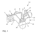
- FIG. 1 shows in a perspective view formed as a door hinge 1 hinge 2 of a motor vehicle not shown here.
- the hinge part 2 has a first hinge part 3 and a second hinge part 4, which are connected to each other in an articulated manner about an axis of rotation 5.
- FIGS. 2A to 2F show the first hinge part 3 in different representations, wherein FIG. 2A shows the hinge part 3 in a perspective view, while FIGS. 2B to 2F Show parts of the hinge part 3.
- the hinge part 3 has a made of plastic, in particular fiberglass reinforced plastic base 6, as in Figure 2C is shown.
- the base part 6 has a - seen in a plan view - substantially angular contour, wherein a leg serves as a connecting flange 7 for fastening the hinge part 3 on the bodywork, in particular on a support column of the motor vehicle.
- the other leg has at its free end a receptacle 8 for a bearing pin 9, as in FIG. 2D is shown on.
- the receptacle 8 has a corrugation 10 which extends axially on the inside of the receptacle 8.
- the bearing pin 9 has at one end 11 a corresponding corrugation 12, which cooperates with the corrugation 10 rotationally inhibited, when the bearing pin 9 is inserted with the end 11 in the receptacle 8.
- the other end 13 of the bearing pin 3 is formed substantially circular cylindrical and is in the inserted state of the bearing pin 9 in the base 6 free.
- the bearing pin 9 has centrally over the entire circumference extending radial projection 14, which serves as Einsteckanschlag or axial stop for the bearing pin 9, and limits the insertion depth of the bearing pin 9 in the receptacle 8.
- Figure 2E shows the base 6 with appropriately inserted bearing pin. 9
- the base 6 has a receptacle for a threaded bushing 15, as in Figure 2F is shown.
- the threaded bush 15 is arranged on the connecting flange 7. It preferably points, as in Figure 2F represented on its outer shell side a corrugation 16, which cooperates with a corresponding corrugation of the not shown here detail of the base 6 as rotation.
- a screw 17 for fixing the hinge part 3 to a body part, in particular on a support bracket of the body of the motor vehicle eincited- or screwed, as in FIG. 1 shown.
- the base part 6 Adjacent to the receptacle for the threaded bushing 15, the base part 6 also in the region of the connection flange 7 on a through hole or opening 18, through which also a screw 19, as in FIG. 1 shown, for fastening the hinge part 3 is feasible.
- the base part 6 is surrounded on its outer shell wall 20 by a support structure 21, the carbon fiber reinforced formed and in FIG. 2B is shown as a single part.
- the carrier material of the support structure 21 is preferably also made of plastic, wherein the contour of the support structure 21 corresponds to the outer contour of the base part 6.
- the support structure 21 thus forms a hollow profile an outer shell of the base 6, as in particular in FIG. 2A shown.
- the support structure 21 can in principle be pushed onto the finished molded base 6.
- the glass fiber reinforced plastic material of the base part 6 is injected into the shaped support structure 21, whereby a tight connection between the base 6 and the support structure 21 is ensured. If the temperature of the injected plastic is selected appropriately, Moreover, a material or material connection between the support structure 21 and the base 6 can also be achieved.
- the support structure 21 has an opening, in particular in FIG. 2A can be seen, so that the screw 19 can penetrate both the support structure 21 and the flange portion of the base 6. Also in the region of the threaded bush 15, the support structure 21 with a corresponding opening, as in particular from FIG. 2B visible, provided.
- FIGS. 3A to 3D show the hinge part 4, which is formed as a door-side hinge part 4, wherein FIG. 3A shows a perspective view of the hinge part 4 and the Figures 3B and 3D Individual parts of the hinge part 4.
- the hinge part 4 a formed from glass fiber reinforced plastic base 22, as in FIG. 3C is shown, and surrounding the base 22 carbon fiber reinforced support structure 23, which is formed as a hollow profile and in FIG. 3B is shown on.
- the hinge part 4 instead of a bearing pin 9, the hinge part 4 on a bearing bush 24, which is made of metal and held in a receptacle 25 of the base 22.
- the support structure 23 is in FIG. 3B shown in perspective.
- the hinge part 4 is produced in that the plastic mass of the base part 22 is preferably injected into the hollow profile of the support structure 23, so that a particularly dense and resilient connection is formed. Particularly preferably, the injection temperature is selected such that a cohesive connection between base 22 and support structure 23 is formed.
- the hinge part 4 also has a connection flange 27, which serves for fastening the hinge part 4 to a door of the motor vehicle.
- connection flange 27 which is a leg of the angularly formed hinge part 4
- an opening 28 for receiving a screw 29, as in FIG. 1 shown provided in the connecting flange 27, which is a leg of the angularly formed hinge part 4, an opening 28 for receiving a screw 29, as in FIG. 1 shown, provided.
- the bearing bush 24, which is held in a form-fitting manner in the base part 22, has a circular cylindrical shape, its inner diameter substantially corresponding to the outer diameter of the end 13 of the bearing bolt 9 corresponds, so that bushing 24 and bearing pin 9 as the axis of rotation 5 forming pivot or rotary joint are merge to the hinge 2 according to FIG. 1 to build.
- the bearing pin 9 rotatably rests in the bearing bush 24.
- FIG. 3A it is also conceivable to provide recesses in the support structure 23 or also 21, through which the injected plastic compound of the respective base part 6 or 22 can pass outward from the hollow profile of the respective support structure 21, 23, for example as in FIG FIG. 3A shown to form an outwardly projecting rib 29.
- the metal parts are already encapsulated with the injection of the glass-fiber-reinforced plastic material in the respective support structure 21, 23, whereby a particularly secure attachment and a particularly resilient hinge 2 is offered in total.
Abstract
Description
Die Erfindung betrifft ein Scharnier, insbesondere ein Türscharnier für Kraftfahrzeuge, mit einem einen Lagerbolzen aufweisenden ersten Scharnierteil und mit einem eine mit dem Lagerbolzen zusammenwirkende Lagerbuchse aufweisenden zweiten Scharnierteil, wobei mindestens eines der Scharnierteile zumindest im Wesentlichen aus Kunststoff gefertigt ist.The invention relates to a hinge, in particular a door hinge for motor vehicles, having a hinge pin having a first hinge part and having a cooperating with the bearing pin bearing bush second hinge part, wherein at least one of the hinge parts is at least substantially made of plastic.
Ferner betrifft die Erfindung ein Scharnierteil für ein Scharnier, insbesondere wie oben beschrieben, wobei das Scharnierteil zumindest im Wesentlichen aus Kunststoff gefertigt ist und einen Lagerbolzen oder eine Lagerbuchse trägt.Furthermore, the invention relates to a hinge part for a hinge, in particular as described above, wherein the hinge part is at least substantially made of plastic and carries a bearing pin or a bearing bush.
Ferner betrifft die Erfindung ein Verfahren zur Herstellung eines Scharnierteils eines Scharniers, insbesondere wie es oben beschrieben wurde, wobei das Scharnierteil zumindest im Wesentlichen aus einer Kunststoffmasse beziehungsweise aus Kunststoff gefertigt und mit einem Lagerbolzen oder mit einer Lagerbuchse versehen wird.Furthermore, the invention relates to a method for producing a hinge part of a hinge, in particular as described above, wherein the hinge part is at least substantially made of a plastic material or plastic and provided with a bearing pin or with a bearing bush.
Scharniere und insbesondere Türscharniere sind im Kraftfahrzeugbau weit verbreitet. Neben der eigentlichen Aufgabe, der Bereitstellung eines Gelenks, müssen im Kraftfahrzeugbau Scharniere noch weitere Anforderungen, die teilweise auch gesetzlichen Bestimmungen unterliegen, erfüllen. So müssen beispielsweise Türscharniere derart ausgebildet sein, dass sie in einem Crashfall hohe Kräfte übertragen können, zur Erhaltung der Sicherheitszelle, und nach dem Crashfall gelöst beziehungsweise getrennt werden können, um ein Entfernen der Tür zur Befreiung von Insassen zu ermöglichen.Hinges and especially door hinges are widely used in automotive engineering. In addition to the actual task of providing a joint, hinges in motor vehicle construction must meet even further requirements, some of which are also subject to legal provisions. For example, door hinges must be designed such that they can transmit high forces in a crash, to maintain the security cell, and can be solved or separated after the crash, to allow removal of the door to release occupants.
Die Offenlegungsschrift
Der Erfindung liegt die Aufgabe zugrunde, ein Scharnier, ein Scharnierteil sowie ein Verfahren zur Herstellung eines Scharnierteils derart zu schaffen, dass das Scharnierteil beziehungsweise das Scharnier trotz geringen Gewichts eine hohe Belastbarkeit aufweist.The invention has for its object to provide a hinge, a hinge part and a method for producing a hinge part such that the hinge part or the hinge despite high weight has a high load capacity.
Die der Erfindung zugrunde liegende Aufgabe wird jeweils durch ein Scharnier mit den Merkmalen des Anspruchs 1, durch ein Scharnierteil mit den Merkmalen des Anspruchs 9 sowie durch ein Verfahren zur Herstellung eines Scharniers mit den Merkmalen des Anspruchs 10 gelöst.The object underlying the invention is achieved in each case by a hinge with the features of
Das erfindungsgemäße Scharnier mit den Merkmalen des Anspruchs 1 hat den Vorteil, dass es insgesamt kleiner und leichter ausgebildet werden kann als ein aus dem Stand der Technik bekanntes Scharnier, um die gleichen Kräfte sicher aufnehmen zu können. Erfindungsgemäß ist hierzu vorgesehen, dass das mindestens eine Scharnierteil, das zumindest im Wesentlichen aus Kunststoff gefertigt ist, eine kohlenstofffaserverstärkte Stützstruktur aufweist. Die kohlenstofffaserverstärkte Stützstruktur ist besonders leicht und gleichzeitig hochbelastbar, wodurch sich die oben genannten Vorteile ergeben. Die Belastbarkeit des Scharniers ergibt sich somit zum großen Teil aus der Stützstruktur, wodurch die Anforderungen an den übrigen Kunststoff geringer ausfallen.The hinge according to the invention with the features of
Besonders bevorzugt weisen beide Scharnierteile eine kohlenstofffaserverstärkte Stützstruktur auf, sodass die miteinander wirkenden Scharnierteile des Scharniers gleichgeartet sind und insofern beide die oben genannten Vorteile aufweisen. Insgesamt wird hierdurch ein Scharnier geschaffen, das einerseits leicht und andererseits besonders leistungsfähig ist. Da sich die Form des Scharniers im Vergleich zu einem herkömmlichen Scharnier nicht oder nicht grundlegend ändert, erfüllt das erfindungsgemäße Scharnier auch weiterhin die Anforderungen an die Lösbarkeit beziehungsweise Trennbarkeit der Scharnierteile.Particularly preferably, both hinge parts on a carbon fiber reinforced support structure, so that the hinge parts of the hinge acting together are gleichgeartet and so far both have the advantages mentioned above. Overall, this creates a hinge that is lightweight on the one hand and very efficient on the other. Since the shape of the hinge does not change or does not fundamentally change compared to a conventional hinge, the hinge according to the invention continues to meet the requirements for releasability or separability of the hinge parts.
Gemäß einer vorteilhaften Weiterbildung der Erfindung ist vorgesehen, dass die jeweilige Stützstruktur als Hohlprofil ausgebildet ist. Dadurch bildet die Stützstruktur eine geschlossene Stützwand, die besonders belastungsfähig ist. Vorzugsweise entspricht die Höhe des Hohlprofils der Höhe des Grundteils. Besonders bevorzugt umgibt die so gestaltete Stützstruktur den Kunststoff des Scharniers umfänglich, wodurch die Belastbarkeit des Scharniers optimiert wird. Vorzugsweise bildet der Kunststoff ein innenliegendes Grundteil, dessen Außenkontur bevorzugt der Innenkontur des Hohlprofils entspricht, um eine feste Verbindung zu erzeugen. Bevorzugt sind der Lagerbolzen oder die Lagerbuchse an beziehungsweise in dem Grundteil gehalten.According to an advantageous embodiment of the invention it is provided that the respective support structure is formed as a hollow profile. As a result, the support structure forms a closed support wall, which is particularly resilient. Preferably, the height of the hollow profile corresponds to the height of the base part. Particularly preferably, the support structure designed in this way circumferentially surrounds the plastic of the hinge, whereby the load capacity of the hinge is optimized. Preferably, the plastic forms an inner base part whose outer contour preferably corresponds to the inner contour of the hollow profile in order to produce a firm connection. Preferably, the bearing pin or the bearing bush are held on or in the base part.
Bevorzugt ist das Hohlprofil, wie bereits erwähnt, mit dem Kunststoff ausgefüllt, wodurch ein kompaktes und stabiles Scharnier geboten wird. Besonders bevorzugt ist das Hohlprofil mit dem Kunststoff ausgespritzt. Dadurch wird auf einfache Art und Weise eine Anpassung des Grundteils an das Hohlprofil erreicht. Gleichzeitig lässt sich hierdurch das Scharnierteil insgesamt besonders einfach herstellen.Preferably, the hollow profile, as already mentioned, filled with the plastic, whereby a compact and stable hinge is offered. Particularly preferably, the hollow profile is sprayed with the plastic. As a result, an adaptation of the base to the hollow profile is achieved in a simple manner. At the same time, this makes the hinge part overall particularly easy to produce.
Gemäß einer vorteilhaften Weiterbildung der Erfindung ist vorgesehen, dass der Lagerbolzen und/oder die Lagerbuchse zumindest bereichsweise in dem jeweiligen Kunststoff eingebettet sind. Das Einbetten kann dabei durch den Spritzvorgang oder auch nachträglich durch ein Einbringen des Lagerbolzens und/oder der Lagerbuchse in den beinahe oder vollständig ausgehärteten Kunststoff erfolgen. Vorzugsweise ist das jeweilige Grundteil mit entsprechenden Aufnahmen versehen. Insbesondere durch das Umspritzen des Lagerbolzens oder der Lagerbuchse während des Ausspritzens des Hohlprofils lässt sich eine sichere Befestigung des Lagerbolzens beziehungsweise der Lagerbuchse an dem Scharnier gewährleisten.According to an advantageous embodiment of the invention it is provided that the bearing pin and / or the bearing bush are at least partially embedded in the respective plastic. The embedding can be done by the injection process or subsequently by introducing the bearing pin and / or the bearing bush in the almost or fully cured plastic. Preferably, the respective base part is provided with corresponding receptacles. In particular, by the encapsulation of the bearing pin or the bearing bush during the ejection of the hollow profile can ensure a secure attachment of the bearing pin or the bearing bush to the hinge.
Bevorzugt ist der Kunststoff faserverstärkt, insbesondere glasfaserverstärkt. Dadurch wird die Festigkeit des Grundteils erhöht. Die kohlenstofffaserverstärkte Stützstruktur ist vorzugsweise als Faserverbundwerkstoff auf Kunststoffbasis gefertigt. Dadurch, dass Stützstruktur und Grundteil einen Kunststoffanteil aufweisen, lassen sich diese auf einfache Art und Weise fest miteinander verbinden. Insbesondere wenn die Temperatur des eingespritzten Kunststoffs in das Hohlprofil den Schmelzpunkt des Kunststoffs der Stützstruktur übersteigt, erfolgt eine material- beziehungsweise stoffschlüssige Verbindung der beiden Elemente miteinander, die eine hohe Belastbarkeit des jeweiligen Scharnierteils bewirkt.The plastic is preferably fiber-reinforced, in particular glass-fiber reinforced. This increases the strength of the base. The carbon fiber reinforced support structure is preferably made as a plastic-based fiber composite. The fact that the support structure and base have a plastic content, these can be firmly connected to each other in a simple manner. In particular, when the temperature of the injected plastic in the hollow profile exceeds the melting point of the plastic of the support structure, a material or cohesive connection of the two elements takes place together, which causes a high load capacity of the respective hinge part.
Gemäß einer vorteilhaften Weiterbildung der Erfindung ist vorgesehen, dass der Lagerbolzen und/oder die Lagerbuchse an ihrer jeweiligen Mantelaußenwand wenigstens abschnittsweise in dem vom Kunststoff umgebenen Bereich eine Riffelung zur Verdrehsicherung aufweisen. Die Riffelung erstreckt sich zweckmäßigerweise in Axialerstreckung des Lagerbolzens beziehungsweise der Lagerbuchse, wodurch eine formschlüssige Verdrehsicherung in Umfangsrichtung auf einfache Art und Weise geboten wird. Vorzugsweise erstreckt sich die Riffelung über den gesamten von Kunststoff umgebenen Abschnitt der Lagerbuchse beziehungsweise des Lagerbolzens. Hierdurch wird die maximale Kraftübertragung - in Umfangsrichtung gesehen - gewährleistet. Zur axialen Sicherung weisen der Lagerbolzen und/oder die Lagerbuchse jeweils bevorzugt wenigstens einen Radialvorsprung auf, der wenigstens eine Anlageschulter in axialer Richtung bildet. Durch den Radialvorsprung wird auf einfacher Art und Weise eine Verliersicherung für den Lagerbolzen und/oder die Lagerbuchse gebildet. Vorzugsweise weisen der Lagerbolzen und/oder Lagerbuchse in einem freiliegenden Abschnitt eine Aufnahme für einen Sicherungs- beziehungsweise Sperrring auf, der nachträglich angebracht beziehungsweise entfernt werden kann. Mittels der Sicherungs- oder Sperrrings lassen sich der Lagerbolzen und/oder die Lagerbuchse verliersicher an dem jeweiligen Scharnierteil anordnen. Ist beispielsweise der Lagerbolzen einendig mit dem Radialvorsprung und anderendig mit der Aufnahme für den Sicherungsring versehen, so lässt sich der Lagerbolzen mit dem die Aufnahme aufweisenden Ende in die entsprechende Öffnung des Scharnierteils einführen bis der Radialvorsprung in Anlagekontakt mit dem Scharnierteil kommt. Die dann auf der anderen Seite des Scharnierteils zweckmäßigerweise freiliegende Aufnahme wird dann mit dem Sicherungsring versehen, wodurch der Lagerbolzen auf einfache Art und Weise insgesamt verliersicher an dem Scharnierteil gehalten ist.According to an advantageous embodiment of the invention it is provided that the bearing pin and / or the bushing have at least partially in their area surrounding the plastic a corrugation for preventing rotation on their respective outer shell wall. The corrugation expediently extends in axial extension of the bearing pin or the bearing bush, whereby a positive rotation in the circumferential direction is offered in a simple manner. Preferably, the corrugation extends over the entire area surrounded by plastic portion of the bearing bush or the bearing pin. As a result, the maximum power transmission - seen in the circumferential direction - guaranteed. For axial securing, the bearing pin and / or the bearing bush preferably each have at least one radial projection, which forms at least one contact shoulder in the axial direction. Due to the radial projection is a simple way a captive for the bearing pin and / or the bearing bush educated. Preferably, the bearing pin and / or bearing bush in an exposed portion of a receptacle for a locking or locking ring, which can be retrofitted or removed. By means of the securing or locking ring, the bearing pin and / or the bearing bush can be arranged captively on the respective hinge part. For example, if the bearing pin unilaterally with the radial projection and otherwise provided with the receptacle for the locking ring, so can the bearing pin with the receiving end having introduced into the corresponding opening of the hinge part until the radial projection comes into abutting contact with the hinge part. The then expediently exposed on the other side of the hinge portion recording is then provided with the locking ring, whereby the bearing pin is held in a simple manner total captive on the hinge part.
Weiterhin ist bevorzugt vorgesehen, dass das erste und/oder das zweite Scharnierteil mindestens eine Gewindebuchse aufweisen, die zumindest im Wesentlichen von dem Kunststoff gehalten ist. Die Gewindebuchse weist, wie der Name schon sagt, ein Gewinde auf, und dient vorzugsweise zur Befestigung des jeweiligen Scharnierteils an der Karosserie oder einer Tür des Kraftfahrzeugs. Bevorzugt weist die Gewindebuchse hierzu ein Innengewinde auf und ist in einer Aufnahme des Grundteils angeordnet. Besonders bevorzugt ist die Gewindebuchse becherförmig ausgebildet, sodass sie mit der Kunststoffmasse des Grundteils umspritzt werden kann, ohne dass Kunststoff in den Gewindebereich gelangt. Vorzugsweise weist die Stützstruktur eine Öffnung im Bereich der Gewindebuchse auf, sodass diese von außen durch die Stützstruktur hindurch zugängig ist.Furthermore, it is preferably provided that the first and / or the second hinge part have at least one threaded bush, which is at least substantially held by the plastic. The threaded bushing has, as the name implies, a thread, and is preferably used to attach the respective hinge part to the body or a door of the motor vehicle. For this purpose, the threaded bushing preferably has an internal thread and is arranged in a receptacle of the base part. Particularly preferably, the threaded bushing is cup-shaped, so that it can be encapsulated with the plastic mass of the base without plastic enters the threaded area. Preferably, the support structure has an opening in the region of the threaded bush, so that it is accessible from the outside through the support structure.
Vorzugsweise weist die Gewindebuchse an ihrer Mantelaußenseite eine mit dem Kunststoff zusammenwirkende Riffelung zur Verdrehsicherung auf, sodass beim Anziehen einer mit der Gewindebuchse zusammenwirkenden Schraube zur Befestigung des Scharnierteils hohe Anziehdrehmomente erreicht werden können, ohne dass sich die Gewindebuchse löst.Preferably, the threaded bushing on its outer shell side cooperating with the plastic corrugations to prevent rotation, so when tightening a co-operating with the threaded bush screw for attaching the hinge part high tightening torques can be achieved without the threaded bush dissolves.
Das erfindungsgemäße Scharnierteil mit den Merkmalen des Anspruchs 9 zeichnet sich dadurch aus, dass es eine kohlenstofffaserverstärkte Stützstruktur aufweist. Hierdurch ergeben sich die oben bereits genannten Vorteile, insbesondere bezüglich der Belastbarkeit und des geringen Gewichts. Vorteilhafte Weiterbildungen des Scharnierteils ergeben sich aus den oben genannten Merkmalen und den Ansprüchen.The hinge part according to the invention with the features of
Das erfindungsgemäße Verfahren zur Herstellung eines Scharnierteils mit den Merkmalen des Anspruchs 10 zeichnet sich dadurch aus, dass zunächst eine kohlenstofffasernverstärkte Stützstruktur bereitgestellt und dann mit der Kunststoffmasse beziehungsweise mit dem Kunststoff versehen wird. Besonders bevorzugt wird die Kunststoffmasse durch einen Spritzvorgang auf die Stützstruktur aufgebracht oder in die Stützstruktur eingebracht. Vorteilhafterweise wird die Stützstruktur als Hohlprofil bereitgestellt und die Kunststoffmasse in das Hohlprofil hineingespritzt. Gemäß einer vorteilhaften Weiterbildung der Erfindung ist vorgesehen, dass die Stützstruktur aus einem kohlenstofffaserverstärkten Strang-Hohlprofil hergestellt wird, wobei das Strangprofil vorzugsweise bereits die Kontur der Stützstruktur aufweist oder wobei ein von dem Strang abgetrennter Abschnitt durch einen nachfolgenden Bearbeitungsschritt in die gewünschte Struktur beziehungsweise Form gebracht wird. Insbesondere die Stirnseiten des Hohlprofils werden nachträglich beispielsweise durch Stanz-, Bohr- oder Schneidvorgänge bearbeitet, um die gewünschte Scharnierteilform zu erhalten. Vorzugsweise wird der Lagerbolzen oder die Lagerbuchse von dem Kunststoff umspritzt, wie zuvor beschrieben. Insgesamt wird hierdurch auf einfache Art und Weise ein Scharnierteil hergestellt, das leicht und belastbar ist.The inventive method for producing a hinge part with the features of
Im Folgenden soll die Erfindung anhand der Zeichnungen näher erläutert werden. Dazu zeigen:
Figur 1- ein Türscharnier eines Kraftfahrzeugs in einer perspektivischen Darstellung,
- Figuren 2A bis 2F
- ein erstes Scharnierteil des Türscharniers und
- Figuren 3A bis 3D
- ein zweites Scharnierteil des Türscharniers.
- FIG. 1
- a door hinge of a motor vehicle in a perspective view,
- FIGS. 2A to 2F
- a first hinge part of the door hinge and
- FIGS. 3A to 3D
- a second hinge part of the door hinge.
Der andere Schenkel weist an seinem freien Ende eine Aufnahme 8 für einen Lagerbolzen 9, wie er in
Weiterhin weist das Grundteil 6 eine Aufnahme für eine Gewindebuchse 15 auf, wie sie in
Benachbart zu der Aufnahme für die Gewindebuchse 15 weist das Grundteil 6 ebenfalls im Bereich des Anschlussflanschs 7 eine Durchbohrung beziehungsweise Öffnung 18 auf, durch welche ebenfalls eine Schraube 19, wie in
Das Grundteil 6 ist an seiner Mantelaußenwand 20 von einer Stützstruktur 21 umgeben, die kohlenstofffasernverstärkt ausgebildet und in
Korrespondierend zu der Öffnung 18 weist auch die Stützstruktur 21 eine Öffnung auf, wie insbesondere in
Das Zusammenspiel der kohlenstofffasernverstärkten Stützstruktur 21 mit dem glasfaserverstärkten Kunststoff des Grundteils 6 führt zu einem leichten und gleichzeitig besonders belastungsfähigen Scharnierteil 3.The interaction of the carbon-fiber-reinforced
Das zweite Scharnierteil 4 ist vom Prinzip her baugleich ausgeführt.
Zur Montage des Scharniers 2 werden die Scharnierteile 3 und 4 also wie in
Wie am besten aus
Bei der Herstellung ist es denkbar, die Aufnahmen für den Lagerbolzen 9, die Gewindebuchse 15 sowie die Lagerbuchse 24 in dem jeweiligen Grundteil 6 beziehungsweise 22 vorzusehen und anschließend, nach Erhärtung des Kunststoffes, die Elemente einzufügen. Besonders bevorzugt werden die Metallteile jedoch bereits beim Einspritzen der glasfaserverstärkten Kunststoffmasse in die jeweilige Stützstruktur 21, 23 mit umspritzt, wodurch eine besonders sichere Befestigung und ein besonders belastbares Scharnier 2 insgesamt geboten wird.In the production, it is conceivable to provide the receptacles for the
Claims (10)
Applications Claiming Priority (1)
| Application Number | Priority Date | Filing Date | Title |
|---|---|---|---|
| DE102012004810A DE102012004810A1 (en) | 2012-03-08 | 2012-03-08 | Hinge, hinge part and method for producing a hinge part |
Publications (3)
| Publication Number | Publication Date |
|---|---|
| EP2636829A2 true EP2636829A2 (en) | 2013-09-11 |
| EP2636829A3 EP2636829A3 (en) | 2017-12-27 |
| EP2636829B1 EP2636829B1 (en) | 2019-05-22 |
Family
ID=47739108
Family Applications (1)
| Application Number | Title | Priority Date | Filing Date |
|---|---|---|---|
| EP13154929.7A Active EP2636829B1 (en) | 2012-03-08 | 2013-02-12 | Hinge, hinge part and method for producing a hinge part |
Country Status (2)
| Country | Link |
|---|---|
| EP (1) | EP2636829B1 (en) |
| DE (1) | DE102012004810A1 (en) |
Families Citing this family (5)
| Publication number | Priority date | Publication date | Assignee | Title |
|---|---|---|---|---|
| DE102013216500B4 (en) * | 2013-08-20 | 2020-09-10 | Bayerische Motoren Werke Aktiengesellschaft | Hinge for holding a wing element and holding arrangement of a wing element on a body part of a body of a motor vehicle |
| DE102013015484B3 (en) * | 2013-09-19 | 2014-07-10 | Edscha Engineering Gmbh | Motor vehicle hinge has hinge half which is fastened at one motor vehicle door and a door frame, where hinge pin is mounted at bore of support structure |
| DE202013008268U1 (en) | 2013-09-19 | 2013-10-08 | Edscha Engineering Gmbh | Motor vehicle hinge |
| DE102015115162B4 (en) | 2015-09-09 | 2022-10-27 | Dr. Ing. H.C. F. Porsche Aktiengesellschaft | Hinge for a lid of a motor vehicle |
| DE102016108367B4 (en) | 2016-05-04 | 2022-06-09 | Edscha Engineering Gmbh | Vehicle hinge and method of manufacturing an attachment part of the vehicle hinge |
Citations (1)
| Publication number | Priority date | Publication date | Assignee | Title |
|---|---|---|---|---|
| DE10330162A1 (en) | 2003-07-04 | 2005-01-27 | Daimlerchrysler Ag | Automobile door hinge incorporates two-part brake and clamp with interface having large static friction in relation to sliding friction |
Family Cites Families (2)
| Publication number | Priority date | Publication date | Assignee | Title |
|---|---|---|---|---|
| DE3730329A1 (en) * | 1987-09-10 | 1989-03-30 | Hackelsberger Mussbach Metall | Hinge for motor-vehicle side doors |
| EP2330267B1 (en) * | 2010-08-25 | 2013-12-25 | Metalsa Automotive GmbH | Vehicle cowling hinge |
-
2012
- 2012-03-08 DE DE102012004810A patent/DE102012004810A1/en not_active Withdrawn
-
2013
- 2013-02-12 EP EP13154929.7A patent/EP2636829B1/en active Active
Patent Citations (1)
| Publication number | Priority date | Publication date | Assignee | Title |
|---|---|---|---|---|
| DE10330162A1 (en) | 2003-07-04 | 2005-01-27 | Daimlerchrysler Ag | Automobile door hinge incorporates two-part brake and clamp with interface having large static friction in relation to sliding friction |
Also Published As
| Publication number | Publication date |
|---|---|
| EP2636829A3 (en) | 2017-12-27 |
| EP2636829B1 (en) | 2019-05-22 |
| DE102012004810A1 (en) | 2013-09-12 |
Similar Documents
| Publication | Publication Date | Title |
|---|---|---|
| DE102010041791B4 (en) | vehicle component | |
| EP2759423B1 (en) | Suspension arm made of fibre-reinforced plastic for a wheel suspension of a vehicle | |
| EP2636829B1 (en) | Hinge, hinge part and method for producing a hinge part | |
| EP2906839B1 (en) | Component with sealing plug and method for the insert moulding of a component insert | |
| EP3042090B1 (en) | Connecting insert and an embedding method and a production method therefor | |
| EP3867036B1 (en) | Vehicle component for a motor vehicle and method for producing a vehicle component of this kind | |
| WO2019072556A1 (en) | Angle coupling | |
| WO2015155247A1 (en) | Bearing arrangement and method for producing same | |
| WO2009010053A1 (en) | Hybrid control arm for a vehicle | |
| EP2764260A1 (en) | Connecting assembly for a vehicle | |
| DE102010054094B3 (en) | Force application element for fixing in or on fiber-plastic composite component, has plastic structure having double-cone-shape in which base surface and contact surfaces are made of bulk molding compound | |
| EP3701157B1 (en) | Semifinished product for producing a fiber-reinforced composite element having a fastening hole or a fastening protrusion, composite element and method for producing a composite element | |
| WO2007073986A1 (en) | Cylinder head cover in composite type of construction | |
| EP3581743A1 (en) | Catch arm for a door check unit, door check unit with catch arm, vehicle door with door check unit, as well as vehicle with vehicle side doors with door check unit | |
| DE102016210123A1 (en) | Stiffening component for a structure of an aircraft or spacecraft, aircraft or spacecraft, and method | |
| DE102007036554B4 (en) | Lid-bearing assembly and method for mounting an actuator shaft | |
| DE102004061057C5 (en) | Ball joint connection between a pin and a fastening part | |
| WO2023094508A1 (en) | Coupling rod and method for producing same | |
| EP2876980B1 (en) | Plastic housing with insert | |
| EP2978564B2 (en) | Clamping nest having fixing elements | |
| DE202019104970U1 (en) | Ball stud | |
| DE102017115071B4 (en) | wheel bearing unit | |
| EP3947992A1 (en) | Ball joint for a chassis of a vehicle and method for producing a ball joint of this kind | |
| DE102014207600B4 (en) | Method for producing a gear housing and gear with a gear housing | |
| DE102012019486A1 (en) | Door for motor vehicle, has connecting element which is projected through recess of the inner portion accommodated with the reinforcing element |
Legal Events
| Date | Code | Title | Description |
|---|---|---|---|
| PUAI | Public reference made under article 153(3) epc to a published international application that has entered the european phase |
Free format text: ORIGINAL CODE: 0009012 |
|
| AK | Designated contracting states |
Kind code of ref document: A2 Designated state(s): AL AT BE BG CH CY CZ DE DK EE ES FI FR GB GR HR HU IE IS IT LI LT LU LV MC MK MT NL NO PL PT RO RS SE SI SK SM TR |
|
| AX | Request for extension of the european patent |
Extension state: BA ME |
|
| PUAL | Search report despatched |
Free format text: ORIGINAL CODE: 0009013 |
|
| AK | Designated contracting states |
Kind code of ref document: A3 Designated state(s): AL AT BE BG CH CY CZ DE DK EE ES FI FR GB GR HR HU IE IS IT LI LT LU LV MC MK MT NL NO PL PT RO RS SE SI SK SM TR |
|
| AX | Request for extension of the european patent |
Extension state: BA ME |
|
| RIC1 | Information provided on ipc code assigned before grant |
Ipc: E05D 9/00 20060101ALI20171123BHEP Ipc: E05D 3/02 20060101AFI20171123BHEP Ipc: E05D 5/06 20060101ALI20171123BHEP |
|
| STAA | Information on the status of an ep patent application or granted ep patent |
Free format text: STATUS: REQUEST FOR EXAMINATION WAS MADE |
|
| 17P | Request for examination filed |
Effective date: 20180627 |
|
| RBV | Designated contracting states (corrected) |
Designated state(s): AL AT BE BG CH CY CZ DE DK EE ES FI FR GB GR HR HU IE IS IT LI LT LU LV MC MK MT NL NO PL PT RO RS SE SI SK SM TR |
|
| GRAP | Despatch of communication of intention to grant a patent |
Free format text: ORIGINAL CODE: EPIDOSNIGR1 |
|
| STAA | Information on the status of an ep patent application or granted ep patent |
Free format text: STATUS: GRANT OF PATENT IS INTENDED |
|
| INTG | Intention to grant announced |
Effective date: 20190108 |
|
| GRAS | Grant fee paid |
Free format text: ORIGINAL CODE: EPIDOSNIGR3 |
|
| GRAA | (expected) grant |
Free format text: ORIGINAL CODE: 0009210 |
|
| STAA | Information on the status of an ep patent application or granted ep patent |
Free format text: STATUS: THE PATENT HAS BEEN GRANTED |
|
| AK | Designated contracting states |
Kind code of ref document: B1 Designated state(s): AL AT BE BG CH CY CZ DE DK EE ES FI FR GB GR HR HU IE IS IT LI LT LU LV MC MK MT NL NO PL PT RO RS SE SI SK SM TR |
|
| REG | Reference to a national code |
Ref country code: GB Ref legal event code: FG4D Free format text: NOT ENGLISH |
|
| REG | Reference to a national code |
Ref country code: CH Ref legal event code: EP |
|
| REG | Reference to a national code |
Ref country code: IE Ref legal event code: FG4D Free format text: LANGUAGE OF EP DOCUMENT: GERMAN |
|
| REG | Reference to a national code |
Ref country code: DE Ref legal event code: R096 Ref document number: 502013012863 Country of ref document: DE |
|
| REG | Reference to a national code |
Ref country code: AT Ref legal event code: REF Ref document number: 1136311 Country of ref document: AT Kind code of ref document: T Effective date: 20190615 |
|
| REG | Reference to a national code |
Ref country code: NL Ref legal event code: MP Effective date: 20190522 |
|
| REG | Reference to a national code |
Ref country code: LT Ref legal event code: MG4D |
|
| PG25 | Lapsed in a contracting state [announced via postgrant information from national office to epo] |
Ref country code: AL Free format text: LAPSE BECAUSE OF FAILURE TO SUBMIT A TRANSLATION OF THE DESCRIPTION OR TO PAY THE FEE WITHIN THE PRESCRIBED TIME-LIMIT Effective date: 20190522 Ref country code: ES Free format text: LAPSE BECAUSE OF FAILURE TO SUBMIT A TRANSLATION OF THE DESCRIPTION OR TO PAY THE FEE WITHIN THE PRESCRIBED TIME-LIMIT Effective date: 20190522 Ref country code: PT Free format text: LAPSE BECAUSE OF FAILURE TO SUBMIT A TRANSLATION OF THE DESCRIPTION OR TO PAY THE FEE WITHIN THE PRESCRIBED TIME-LIMIT Effective date: 20190922 Ref country code: NL Free format text: LAPSE BECAUSE OF FAILURE TO SUBMIT A TRANSLATION OF THE DESCRIPTION OR TO PAY THE FEE WITHIN THE PRESCRIBED TIME-LIMIT Effective date: 20190522 Ref country code: NO Free format text: LAPSE BECAUSE OF FAILURE TO SUBMIT A TRANSLATION OF THE DESCRIPTION OR TO PAY THE FEE WITHIN THE PRESCRIBED TIME-LIMIT Effective date: 20190822 Ref country code: LT Free format text: LAPSE BECAUSE OF FAILURE TO SUBMIT A TRANSLATION OF THE DESCRIPTION OR TO PAY THE FEE WITHIN THE PRESCRIBED TIME-LIMIT Effective date: 20190522 Ref country code: FI Free format text: LAPSE BECAUSE OF FAILURE TO SUBMIT A TRANSLATION OF THE DESCRIPTION OR TO PAY THE FEE WITHIN THE PRESCRIBED TIME-LIMIT Effective date: 20190522 Ref country code: SE Free format text: LAPSE BECAUSE OF FAILURE TO SUBMIT A TRANSLATION OF THE DESCRIPTION OR TO PAY THE FEE WITHIN THE PRESCRIBED TIME-LIMIT Effective date: 20190522 Ref country code: HR Free format text: LAPSE BECAUSE OF FAILURE TO SUBMIT A TRANSLATION OF THE DESCRIPTION OR TO PAY THE FEE WITHIN THE PRESCRIBED TIME-LIMIT Effective date: 20190522 |
|
| PG25 | Lapsed in a contracting state [announced via postgrant information from national office to epo] |
Ref country code: RS Free format text: LAPSE BECAUSE OF FAILURE TO SUBMIT A TRANSLATION OF THE DESCRIPTION OR TO PAY THE FEE WITHIN THE PRESCRIBED TIME-LIMIT Effective date: 20190522 Ref country code: LV Free format text: LAPSE BECAUSE OF FAILURE TO SUBMIT A TRANSLATION OF THE DESCRIPTION OR TO PAY THE FEE WITHIN THE PRESCRIBED TIME-LIMIT Effective date: 20190522 Ref country code: GR Free format text: LAPSE BECAUSE OF FAILURE TO SUBMIT A TRANSLATION OF THE DESCRIPTION OR TO PAY THE FEE WITHIN THE PRESCRIBED TIME-LIMIT Effective date: 20190823 Ref country code: BG Free format text: LAPSE BECAUSE OF FAILURE TO SUBMIT A TRANSLATION OF THE DESCRIPTION OR TO PAY THE FEE WITHIN THE PRESCRIBED TIME-LIMIT Effective date: 20190822 |
|
| PG25 | Lapsed in a contracting state [announced via postgrant information from national office to epo] |
Ref country code: DK Free format text: LAPSE BECAUSE OF FAILURE TO SUBMIT A TRANSLATION OF THE DESCRIPTION OR TO PAY THE FEE WITHIN THE PRESCRIBED TIME-LIMIT Effective date: 20190522 Ref country code: EE Free format text: LAPSE BECAUSE OF FAILURE TO SUBMIT A TRANSLATION OF THE DESCRIPTION OR TO PAY THE FEE WITHIN THE PRESCRIBED TIME-LIMIT Effective date: 20190522 Ref country code: CZ Free format text: LAPSE BECAUSE OF FAILURE TO SUBMIT A TRANSLATION OF THE DESCRIPTION OR TO PAY THE FEE WITHIN THE PRESCRIBED TIME-LIMIT Effective date: 20190522 Ref country code: RO Free format text: LAPSE BECAUSE OF FAILURE TO SUBMIT A TRANSLATION OF THE DESCRIPTION OR TO PAY THE FEE WITHIN THE PRESCRIBED TIME-LIMIT Effective date: 20190522 Ref country code: SK Free format text: LAPSE BECAUSE OF FAILURE TO SUBMIT A TRANSLATION OF THE DESCRIPTION OR TO PAY THE FEE WITHIN THE PRESCRIBED TIME-LIMIT Effective date: 20190522 |
|
| REG | Reference to a national code |
Ref country code: DE Ref legal event code: R097 Ref document number: 502013012863 Country of ref document: DE |
|
| PG25 | Lapsed in a contracting state [announced via postgrant information from national office to epo] |
Ref country code: IT Free format text: LAPSE BECAUSE OF FAILURE TO SUBMIT A TRANSLATION OF THE DESCRIPTION OR TO PAY THE FEE WITHIN THE PRESCRIBED TIME-LIMIT Effective date: 20190522 Ref country code: SM Free format text: LAPSE BECAUSE OF FAILURE TO SUBMIT A TRANSLATION OF THE DESCRIPTION OR TO PAY THE FEE WITHIN THE PRESCRIBED TIME-LIMIT Effective date: 20190522 |
|
| PLBE | No opposition filed within time limit |
Free format text: ORIGINAL CODE: 0009261 |
|
| STAA | Information on the status of an ep patent application or granted ep patent |
Free format text: STATUS: NO OPPOSITION FILED WITHIN TIME LIMIT |
|
| PG25 | Lapsed in a contracting state [announced via postgrant information from national office to epo] |
Ref country code: TR Free format text: LAPSE BECAUSE OF FAILURE TO SUBMIT A TRANSLATION OF THE DESCRIPTION OR TO PAY THE FEE WITHIN THE PRESCRIBED TIME-LIMIT Effective date: 20190522 |
|
| 26N | No opposition filed |
Effective date: 20200225 |
|
| PG25 | Lapsed in a contracting state [announced via postgrant information from national office to epo] |
Ref country code: PL Free format text: LAPSE BECAUSE OF FAILURE TO SUBMIT A TRANSLATION OF THE DESCRIPTION OR TO PAY THE FEE WITHIN THE PRESCRIBED TIME-LIMIT Effective date: 20190522 |
|
| PG25 | Lapsed in a contracting state [announced via postgrant information from national office to epo] |
Ref country code: SI Free format text: LAPSE BECAUSE OF FAILURE TO SUBMIT A TRANSLATION OF THE DESCRIPTION OR TO PAY THE FEE WITHIN THE PRESCRIBED TIME-LIMIT Effective date: 20190522 |
|
| REG | Reference to a national code |
Ref country code: CH Ref legal event code: PL |
|
| GBPC | Gb: european patent ceased through non-payment of renewal fee |
Effective date: 20200212 |
|
| REG | Reference to a national code |
Ref country code: BE Ref legal event code: MM Effective date: 20200229 |
|
| PG25 | Lapsed in a contracting state [announced via postgrant information from national office to epo] |
Ref country code: LU Free format text: LAPSE BECAUSE OF NON-PAYMENT OF DUE FEES Effective date: 20200212 Ref country code: MC Free format text: LAPSE BECAUSE OF FAILURE TO SUBMIT A TRANSLATION OF THE DESCRIPTION OR TO PAY THE FEE WITHIN THE PRESCRIBED TIME-LIMIT Effective date: 20190522 |
|
| PG25 | Lapsed in a contracting state [announced via postgrant information from national office to epo] |
Ref country code: LI Free format text: LAPSE BECAUSE OF NON-PAYMENT OF DUE FEES Effective date: 20200229 Ref country code: CH Free format text: LAPSE BECAUSE OF NON-PAYMENT OF DUE FEES Effective date: 20200229 |
|
| PG25 | Lapsed in a contracting state [announced via postgrant information from national office to epo] |
Ref country code: IE Free format text: LAPSE BECAUSE OF NON-PAYMENT OF DUE FEES Effective date: 20200212 Ref country code: FR Free format text: LAPSE BECAUSE OF NON-PAYMENT OF DUE FEES Effective date: 20200229 Ref country code: GB Free format text: LAPSE BECAUSE OF NON-PAYMENT OF DUE FEES Effective date: 20200212 |
|
| PG25 | Lapsed in a contracting state [announced via postgrant information from national office to epo] |
Ref country code: BE Free format text: LAPSE BECAUSE OF NON-PAYMENT OF DUE FEES Effective date: 20200229 |
|
| REG | Reference to a national code |
Ref country code: AT Ref legal event code: MM01 Ref document number: 1136311 Country of ref document: AT Kind code of ref document: T Effective date: 20200212 |
|
| PG25 | Lapsed in a contracting state [announced via postgrant information from national office to epo] |
Ref country code: AT Free format text: LAPSE BECAUSE OF NON-PAYMENT OF DUE FEES Effective date: 20200212 |
|
| PGFP | Annual fee paid to national office [announced via postgrant information from national office to epo] |
Ref country code: DE Payment date: 20210228 Year of fee payment: 9 |
|
| PG25 | Lapsed in a contracting state [announced via postgrant information from national office to epo] |
Ref country code: MT Free format text: LAPSE BECAUSE OF FAILURE TO SUBMIT A TRANSLATION OF THE DESCRIPTION OR TO PAY THE FEE WITHIN THE PRESCRIBED TIME-LIMIT Effective date: 20190522 Ref country code: CY Free format text: LAPSE BECAUSE OF FAILURE TO SUBMIT A TRANSLATION OF THE DESCRIPTION OR TO PAY THE FEE WITHIN THE PRESCRIBED TIME-LIMIT Effective date: 20190522 |
|
| PG25 | Lapsed in a contracting state [announced via postgrant information from national office to epo] |
Ref country code: MK Free format text: LAPSE BECAUSE OF FAILURE TO SUBMIT A TRANSLATION OF THE DESCRIPTION OR TO PAY THE FEE WITHIN THE PRESCRIBED TIME-LIMIT Effective date: 20190522 Ref country code: IS Free format text: LAPSE BECAUSE OF FAILURE TO SUBMIT A TRANSLATION OF THE DESCRIPTION OR TO PAY THE FEE WITHIN THE PRESCRIBED TIME-LIMIT Effective date: 20190922 |
|
| REG | Reference to a national code |
Ref country code: DE Ref legal event code: R119 Ref document number: 502013012863 Country of ref document: DE |
|
| PG25 | Lapsed in a contracting state [announced via postgrant information from national office to epo] |
Ref country code: DE Free format text: LAPSE BECAUSE OF NON-PAYMENT OF DUE FEES Effective date: 20220901 |