EP2636520A1 - Utilisation d'un matériau polymère - Google Patents
Utilisation d'un matériau polymère Download PDFInfo
- Publication number
- EP2636520A1 EP2636520A1 EP13156773.7A EP13156773A EP2636520A1 EP 2636520 A1 EP2636520 A1 EP 2636520A1 EP 13156773 A EP13156773 A EP 13156773A EP 2636520 A1 EP2636520 A1 EP 2636520A1
- Authority
- EP
- European Patent Office
- Prior art keywords
- pipe
- polymer material
- sigma
- molding
- thermal barrier
- Prior art date
- Legal status (The legal status is an assumption and is not a legal conclusion. Google has not performed a legal analysis and makes no representation as to the accuracy of the status listed.)
- Withdrawn
Links
Images


Classifications
-
- B—PERFORMING OPERATIONS; TRANSPORTING
- B32—LAYERED PRODUCTS
- B32B—LAYERED PRODUCTS, i.e. PRODUCTS BUILT-UP OF STRATA OF FLAT OR NON-FLAT, e.g. CELLULAR OR HONEYCOMB, FORM
- B32B5/00—Layered products characterised by the non- homogeneity or physical structure, i.e. comprising a fibrous, filamentary, particulate or foam layer; Layered products characterised by having a layer differing constitutionally or physically in different parts
- B32B5/18—Layered products characterised by the non- homogeneity or physical structure, i.e. comprising a fibrous, filamentary, particulate or foam layer; Layered products characterised by having a layer differing constitutionally or physically in different parts characterised by features of a layer of foamed material
-
- B—PERFORMING OPERATIONS; TRANSPORTING
- B32—LAYERED PRODUCTS
- B32B—LAYERED PRODUCTS, i.e. PRODUCTS BUILT-UP OF STRATA OF FLAT OR NON-FLAT, e.g. CELLULAR OR HONEYCOMB, FORM
- B32B1/00—Layered products having a general shape other than plane
- B32B1/08—Tubular products
-
- B—PERFORMING OPERATIONS; TRANSPORTING
- B32—LAYERED PRODUCTS
- B32B—LAYERED PRODUCTS, i.e. PRODUCTS BUILT-UP OF STRATA OF FLAT OR NON-FLAT, e.g. CELLULAR OR HONEYCOMB, FORM
- B32B27/00—Layered products comprising a layer of synthetic resin
- B32B27/06—Layered products comprising a layer of synthetic resin as the main or only constituent of a layer, which is next to another layer of the same or of a different material
- B32B27/065—Layered products comprising a layer of synthetic resin as the main or only constituent of a layer, which is next to another layer of the same or of a different material of foam
-
- B—PERFORMING OPERATIONS; TRANSPORTING
- B32—LAYERED PRODUCTS
- B32B—LAYERED PRODUCTS, i.e. PRODUCTS BUILT-UP OF STRATA OF FLAT OR NON-FLAT, e.g. CELLULAR OR HONEYCOMB, FORM
- B32B27/00—Layered products comprising a layer of synthetic resin
- B32B27/06—Layered products comprising a layer of synthetic resin as the main or only constituent of a layer, which is next to another layer of the same or of a different material
- B32B27/08—Layered products comprising a layer of synthetic resin as the main or only constituent of a layer, which is next to another layer of the same or of a different material of synthetic resin
-
- B—PERFORMING OPERATIONS; TRANSPORTING
- B32—LAYERED PRODUCTS
- B32B—LAYERED PRODUCTS, i.e. PRODUCTS BUILT-UP OF STRATA OF FLAT OR NON-FLAT, e.g. CELLULAR OR HONEYCOMB, FORM
- B32B27/00—Layered products comprising a layer of synthetic resin
- B32B27/32—Layered products comprising a layer of synthetic resin comprising polyolefins
-
- B—PERFORMING OPERATIONS; TRANSPORTING
- B32—LAYERED PRODUCTS
- B32B—LAYERED PRODUCTS, i.e. PRODUCTS BUILT-UP OF STRATA OF FLAT OR NON-FLAT, e.g. CELLULAR OR HONEYCOMB, FORM
- B32B2266/00—Composition of foam
- B32B2266/02—Organic
- B32B2266/0214—Materials belonging to B32B27/00
- B32B2266/025—Polyolefin
-
- B—PERFORMING OPERATIONS; TRANSPORTING
- B32—LAYERED PRODUCTS
- B32B—LAYERED PRODUCTS, i.e. PRODUCTS BUILT-UP OF STRATA OF FLAT OR NON-FLAT, e.g. CELLULAR OR HONEYCOMB, FORM
- B32B2307/00—Properties of the layers or laminate
- B32B2307/70—Other properties
- B32B2307/724—Permeability to gases, adsorption
- B32B2307/7242—Non-permeable
- B32B2307/7244—Oxygen barrier
-
- B—PERFORMING OPERATIONS; TRANSPORTING
- B32—LAYERED PRODUCTS
- B32B—LAYERED PRODUCTS, i.e. PRODUCTS BUILT-UP OF STRATA OF FLAT OR NON-FLAT, e.g. CELLULAR OR HONEYCOMB, FORM
- B32B2307/00—Properties of the layers or laminate
- B32B2307/70—Other properties
- B32B2307/724—Permeability to gases, adsorption
- B32B2307/7242—Non-permeable
- B32B2307/7246—Water vapor barrier
-
- B—PERFORMING OPERATIONS; TRANSPORTING
- B32—LAYERED PRODUCTS
- B32B—LAYERED PRODUCTS, i.e. PRODUCTS BUILT-UP OF STRATA OF FLAT OR NON-FLAT, e.g. CELLULAR OR HONEYCOMB, FORM
- B32B2597/00—Tubular articles, e.g. hoses, pipes
-
- F—MECHANICAL ENGINEERING; LIGHTING; HEATING; WEAPONS; BLASTING
- F16—ENGINEERING ELEMENTS AND UNITS; GENERAL MEASURES FOR PRODUCING AND MAINTAINING EFFECTIVE FUNCTIONING OF MACHINES OR INSTALLATIONS; THERMAL INSULATION IN GENERAL
- F16L—PIPES; JOINTS OR FITTINGS FOR PIPES; SUPPORTS FOR PIPES, CABLES OR PROTECTIVE TUBING; MEANS FOR THERMAL INSULATION IN GENERAL
- F16L59/00—Thermal insulation in general
- F16L59/14—Arrangements for the insulation of pipes or pipe systems
- F16L59/143—Pre-insulated pipes
-
- F—MECHANICAL ENGINEERING; LIGHTING; HEATING; WEAPONS; BLASTING
- F16—ENGINEERING ELEMENTS AND UNITS; GENERAL MEASURES FOR PRODUCING AND MAINTAINING EFFECTIVE FUNCTIONING OF MACHINES OR INSTALLATIONS; THERMAL INSULATION IN GENERAL
- F16L—PIPES; JOINTS OR FITTINGS FOR PIPES; SUPPORTS FOR PIPES, CABLES OR PROTECTIVE TUBING; MEANS FOR THERMAL INSULATION IN GENERAL
- F16L59/00—Thermal insulation in general
- F16L59/14—Arrangements for the insulation of pipes or pipe systems
- F16L59/153—Arrangements for the insulation of pipes or pipe systems for flexible pipes
-
- F—MECHANICAL ENGINEERING; LIGHTING; HEATING; WEAPONS; BLASTING
- F16—ENGINEERING ELEMENTS AND UNITS; GENERAL MEASURES FOR PRODUCING AND MAINTAINING EFFECTIVE FUNCTIONING OF MACHINES OR INSTALLATIONS; THERMAL INSULATION IN GENERAL
- F16L—PIPES; JOINTS OR FITTINGS FOR PIPES; SUPPORTS FOR PIPES, CABLES OR PROTECTIVE TUBING; MEANS FOR THERMAL INSULATION IN GENERAL
- F16L59/00—Thermal insulation in general
- F16L59/14—Arrangements for the insulation of pipes or pipe systems
- F16L59/16—Arrangements specially adapted to local requirements at flanges, junctions, valves or the like
- F16L59/163—Branch units ; Insulation forming a whole with branches
-
- F—MECHANICAL ENGINEERING; LIGHTING; HEATING; WEAPONS; BLASTING
- F24—HEATING; RANGES; VENTILATING
- F24D—DOMESTIC- OR SPACE-HEATING SYSTEMS, e.g. CENTRAL HEATING SYSTEMS; DOMESTIC HOT-WATER SUPPLY SYSTEMS; ELEMENTS OR COMPONENTS THEREFOR
- F24D10/00—District heating systems
-
- Y—GENERAL TAGGING OF NEW TECHNOLOGICAL DEVELOPMENTS; GENERAL TAGGING OF CROSS-SECTIONAL TECHNOLOGIES SPANNING OVER SEVERAL SECTIONS OF THE IPC; TECHNICAL SUBJECTS COVERED BY FORMER USPC CROSS-REFERENCE ART COLLECTIONS [XRACs] AND DIGESTS
- Y02—TECHNOLOGIES OR APPLICATIONS FOR MITIGATION OR ADAPTATION AGAINST CLIMATE CHANGE
- Y02B—CLIMATE CHANGE MITIGATION TECHNOLOGIES RELATED TO BUILDINGS, e.g. HOUSING, HOUSE APPLIANCES OR RELATED END-USER APPLICATIONS
- Y02B30/00—Energy efficient heating, ventilation or air conditioning [HVAC]
- Y02B30/17—District heating
-
- Y—GENERAL TAGGING OF NEW TECHNOLOGICAL DEVELOPMENTS; GENERAL TAGGING OF CROSS-SECTIONAL TECHNOLOGIES SPANNING OVER SEVERAL SECTIONS OF THE IPC; TECHNICAL SUBJECTS COVERED BY FORMER USPC CROSS-REFERENCE ART COLLECTIONS [XRACs] AND DIGESTS
- Y02—TECHNOLOGIES OR APPLICATIONS FOR MITIGATION OR ADAPTATION AGAINST CLIMATE CHANGE
- Y02E—REDUCTION OF GREENHOUSE GAS [GHG] EMISSIONS, RELATED TO ENERGY GENERATION, TRANSMISSION OR DISTRIBUTION
- Y02E20/00—Combustion technologies with mitigation potential
- Y02E20/14—Combined heat and power generation [CHP]
Definitions
- the invention relates to the use of a polymer material for producing a thermal barrier coating of a multilayer pipe or a thermal barrier coating of a multilayer pipe molding, a method for producing a multilayer pipe or a multilayer molded article and the multilayer pipe or multilayer pipe molding produced by the method.
- district heating pipes are used, which are able to direct the flowing in the pipes heated fluid over very long distances to the consumers, without causing significant heat energy losses.
- the pipes are thermally insulated.
- media-carrying pipe such as cross-linked polyethylene (PE-X) or steel.
- a very common technique to produce such district heating pipes is, a medium pipe, for example made of PE-X with one or more foam layers of an expanded polymer material such as PE-X or polyethylene (PE) or polypropylene (PP) or polyurethane (PUR), which Make insulation, manufacture.
- a medium pipe for example made of PE-X with one or more foam layers of an expanded polymer material such as PE-X or polyethylene (PE) or polypropylene (PP) or polyurethane (PUR), which Make insulation, manufacture.
- PE polyethylene
- PP polypropylene
- PUR polyurethane
- the invention which has set itself the task of selecting a suitable polymer material which meets the high demands placed on district heating pipes, and to provide for the production of a thermal barrier coating for a pipe arrangement of a district heating network.
- the polymer material should be easily moldable, so as to provide the pipe or pipe fitting in a simple manufacturing technique can.
- Such a tube or such a tubular molding with a thermal barrier coating according to the present invention can be produced in a simple manner, causing little Manufacturing costs, is durable, withstands the prevailing pressures and temperatures of the medium conveyed in them over long periods of time and is durable with regard to the effectiveness of the heat insulation.
- such a pipe or pipe fitting resists the conditions under which a district heating network is operated. These include the persistence of temperature and any pressure fluctuations of the fluid on the thermal barrier coating of polymer material, pressure spikes and fluctuations as well as temperature peaks and fluctuations. Likewise, the expansion behavior of the material is taken into account, which is crucially influenced by temperature and pressure. Finally, a durable material in terms of durable insulation is needed because a district heating network should have a long life. All this is ensured by the use of the polymer material described above.
- the polymer material is a polyethylene.
- a polyethylene is a very easily processable polymer material that can be used both in extrusion and injection molding in order to produce a thermal barrier coating.
- a polyethylene is inert, durable and is not damaged or altered by the temperature of the fluid to be fluid when used in a district heating network, moreover, it is conveniently available.
- the innermost, ie the lumen of the pipe or pipe molding facing layer of the media tube of a polymeric material such as polyethylene (PE), crosslinked polyethylene (PE-X), polypropylene (PP ), Polybutylene (PB), their mixtures or copolymers is formed.
- the media tube may therefore consist of polymer material or contain polymer material.
- the media is made of metal.
- This innermost layer of the pipe or pipe molding comes into contact with the medium to be conductive.
- At least one barrier layer is arranged on the side facing away from the lumen or in the layer of polymer material.
- Such a barrier layer prevents or reduces to a very high degree the passage of substances from the environment into the lumen of the tube or out of the lumen of the tube into the environment. It has proved to be particularly favorable when a barrier layer is used as the barrier layer, which prevents or limits the passage of water vapor and / or the passage of oxygen. In the context of the invention can also be provided that a plurality of barrier layers are provided in a combination.
- thermal barrier coating is disposed on the layer of polymer material or on the barrier layer.
- the polymeric material is physically or chemically foamed with a gas.
- the polymer foam produced in this way can be open-celled or closed-celled. Preference is given to a closed-cell polymer foam, since this has advantages in terms of its thermal insulation properties and a possible water absorption.
- the thermal barrier coating can be multi-layered.
- the material of the thermal barrier coating is selected such that it shows no failure, no degradation or similar changes with respect to the temperature of the medium to be conducted.
- the thickness of the thermal barrier coating is chosen so that the desired thermal insulation effect occurs.
- a diffusion barrier layer to be arranged on the side of the thermal barrier coating facing away from the lumen of the pipe or pipe fitting.
- a diffusion barrier layer arranged there on the thermal barrier coating is suitable for protecting the thermal barrier coating from the ingress of substances from the environment.
- the diffusion barrier layer can also prevent substances from the thermal barrier coating from entering the environment.
- the diffusion barrier layer is designed so that gases from the polymer foam, which forms the thermal barrier coating, do not diffuse outwards into the environment, but remain in the thermal barrier coating and thereby maintain the effectiveness of the thermal barrier coating.
- a protective layer is arranged, which forms the outermost layer of the pipe or pipe molding.
- a very resistant pipe or pipe molding can be made, which ensures a high resistance to damage during storage, transport and installation of pipes or pipe fittings.
- the protective layer can be corrugated or smooth, furthermore, it can be provided that the protective layer consists of a polyethylene (PE) or a polyethylene with increased resistance to tearing or a cross-linked polyethylene (PE-X) or similar resistant materials is made.
- PE polyethylene
- PE-X cross-linked polyethylene
- adhesion promoter layer is arranged between two of the abovementioned layers.
- An adhesive layer causes a particularly strong bond between two adjacent layers, so that an adhesive bond is formed. It is also included in the invention that adhesion promoter layers are formed between all adjoining layers.
- Such a method for producing a multilayer pipe or multilayer pipe molding may be selected as an extrusion process or as an injection molding process or as a blowing process or as an in-line fabrication process or as a combined process from the above.
- a multilayer pipe or a multilayer pipe molding according to the above description can be produced in a favorable manner.
- the method is carried out such that at least one barrier layer is arranged on or in the layer of polymer material.
- Arranging a barrier layer on or in the layer of polymer material can be realized in a simple manner in an extrusion process or in an injection molding process.
- a heat-insulating layer is arranged in the context of the method and a diffusion barrier layer is arranged on the side of the thermal barrier coating facing away from the lumen of the pipe or pipe-shaped part.
- a diffusion barrier layer is arranged in which, in addition to the production of the at least one layer of the multilayer pipe or the multilayer molded part of the polymer material as described above, a heat-insulating layer and a side facing away from the lumen of the pipe or pipe molding side of the thermal barrier coating, a diffusion barrier layer is arranged is particularly advantageous and cheap.
- a multi-layer tubular shaped part is understood to mean, for example, a pipe bend, a branch pipe, a T-piece, a sleeve or an electrofusion coupler, without this enumeration being exhaustive.
- An electric welding sleeve is particularly suitable for connecting pipes with each other or pipes and pipe fittings or pipe fittings with each other. It is understood in the context of the present invention that an electric welding sleeve can be formed so that they can accommodate a pipe, two pipes, three pipes or four pipes and connect with each other or with one or more pipe fittings.
- a pipeline consisting of pipes or pipe parts according to the present invention is particularly advantageous when the connection between the pipes or pipe fittings is made by butt welding.
- a tube 1 is shown in a longitudinal sectional view along the axis.
- the multilayer pipe 1 has a lumen 7 in a media pipe 2 made of polymer material.
- the thermal barrier coating 4 consists of a foamed polymer material.
- the thermal barrier coating 4 has a diffusion barrier layer 5 on its side facing away from the lumen 7 of the multilayer pipe 1.
- a protective layer 6 is disposed adjacent to the diffusion barrier layer 5.
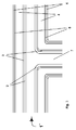
- Fig. 2 is a longitudinal section through a multi-layer pipe bend 1 'shown along its axis.
- the multilayer pipe bend 1 is a pipe molding which allows a connection of pipes 1, 1, not shown here at a certain angle, in the present case about 90 °.
- the lumen 7 of the multilayer pipe bend 1 ' is bounded by a multilayer wall, the construction being analogous, as described above Fig. 1 portrayed. All reference numerals correspond to each other.
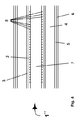
- Fig. 3 shows a T-piece 1 "in a longitudinal sectional view along the axis.
- the lumen 7 of the T-piece 1 is bounded by a multilayer wall whose structure already basically from the description Fig. 1 is known.
- the reference numerals correspond to each other.
- FIG. 4 is reproduced an electric welding sleeve 1 '", which is shown in a longitudinal sectional view along the axis.
- An electric welding sleeve 1 '" is suitable to connect pipes 1, 1 or pipe fittings 1', 1", 1 '", wherein the welding process is initiated by applying an electrical voltage, whereby in the interior of the electrofusion joint 1'" by a heating wire 8 polymer material melt down, which establishes the welded joint.
- the lumen 7 of the electrofusion joint 1 '" is hereby limited by a multilayer wall whose structure in the description of Fig. 1 has already been explained.
- the reference numerals correspond to each other.
Applications Claiming Priority (1)
| Application Number | Priority Date | Filing Date | Title |
|---|---|---|---|
| DE102012101869A DE102012101869A1 (de) | 2012-03-06 | 2012-03-06 | Verwendung eines Polymermaterials |
Publications (1)
| Publication Number | Publication Date |
|---|---|
| EP2636520A1 true EP2636520A1 (fr) | 2013-09-11 |
Family
ID=47891399
Family Applications (1)
| Application Number | Title | Priority Date | Filing Date |
|---|---|---|---|
| EP13156773.7A Withdrawn EP2636520A1 (fr) | 2012-03-06 | 2013-02-26 | Utilisation d'un matériau polymère |
Country Status (2)
| Country | Link |
|---|---|
| EP (1) | EP2636520A1 (fr) |
| DE (1) | DE102012101869A1 (fr) |
Cited By (2)
| Publication number | Priority date | Publication date | Assignee | Title |
|---|---|---|---|---|
| EP2862695A1 (fr) * | 2013-10-15 | 2015-04-22 | REHAU AG + Co | Tuyau en plastique |
| WO2016153956A1 (fr) * | 2015-03-24 | 2016-09-29 | Dow Global Technologies Llc | Procédé pour l'isolation de structures sous-marines complexes |
Citations (7)
| Publication number | Priority date | Publication date | Assignee | Title |
|---|---|---|---|---|
| WO2001094112A1 (fr) * | 2000-06-08 | 2001-12-13 | Wavin B.V. | Tuyau constitue de plusieurs couches |
| WO2001094092A1 (fr) * | 2000-06-06 | 2001-12-13 | Thermaflex International Holding B.V. | Procede de production de produits mousses de polyolefine mousses physiquement, et mousses d'isolation ainsi preparees |
| WO2003020821A1 (fr) * | 2001-08-31 | 2003-03-13 | Dow Global Technologies Inc. | Materiau de polyethylene multimodal |
| DE102004059677A1 (de) * | 2003-12-12 | 2005-09-15 | Hraschan, Jakob | Thermisch isolierte Rohrleitung |
| EP1840444A1 (fr) * | 2006-03-28 | 2007-10-03 | BRUGG Rohr AG, Holding | Ame pour conduite isolée thermiquement |
| WO2008116625A1 (fr) * | 2007-03-26 | 2008-10-02 | Rehau Ag + Co | Tube en plastique |
| US20110256333A1 (en) * | 2010-04-14 | 2011-10-20 | Lutz William G | Polypropylene Compositions |
Family Cites Families (2)
| Publication number | Priority date | Publication date | Assignee | Title |
|---|---|---|---|---|
| DE3216463A1 (de) * | 1982-05-03 | 1983-11-03 | Felten & Guilleaume Energietechnik GmbH, 5000 Köln | Verfahren zum herstellen eines flexiblen fernwaermeleitungsrohres |
| DE29806127U1 (de) * | 1998-04-03 | 1999-07-29 | Hewing Gmbh | Fluidführendes Bauelement für ein Sanitär- und/oder Heizungsinstallationssystem, insbesondere Sanitär- und/oder Heizungsrohr |
-
2012
- 2012-03-06 DE DE102012101869A patent/DE102012101869A1/de not_active Withdrawn
-
2013
- 2013-02-26 EP EP13156773.7A patent/EP2636520A1/fr not_active Withdrawn
Patent Citations (7)
| Publication number | Priority date | Publication date | Assignee | Title |
|---|---|---|---|---|
| WO2001094092A1 (fr) * | 2000-06-06 | 2001-12-13 | Thermaflex International Holding B.V. | Procede de production de produits mousses de polyolefine mousses physiquement, et mousses d'isolation ainsi preparees |
| WO2001094112A1 (fr) * | 2000-06-08 | 2001-12-13 | Wavin B.V. | Tuyau constitue de plusieurs couches |
| WO2003020821A1 (fr) * | 2001-08-31 | 2003-03-13 | Dow Global Technologies Inc. | Materiau de polyethylene multimodal |
| DE102004059677A1 (de) * | 2003-12-12 | 2005-09-15 | Hraschan, Jakob | Thermisch isolierte Rohrleitung |
| EP1840444A1 (fr) * | 2006-03-28 | 2007-10-03 | BRUGG Rohr AG, Holding | Ame pour conduite isolée thermiquement |
| WO2008116625A1 (fr) * | 2007-03-26 | 2008-10-02 | Rehau Ag + Co | Tube en plastique |
| US20110256333A1 (en) * | 2010-04-14 | 2011-10-20 | Lutz William G | Polypropylene Compositions |
Cited By (2)
| Publication number | Priority date | Publication date | Assignee | Title |
|---|---|---|---|---|
| EP2862695A1 (fr) * | 2013-10-15 | 2015-04-22 | REHAU AG + Co | Tuyau en plastique |
| WO2016153956A1 (fr) * | 2015-03-24 | 2016-09-29 | Dow Global Technologies Llc | Procédé pour l'isolation de structures sous-marines complexes |
Also Published As
| Publication number | Publication date |
|---|---|
| DE102012101869A1 (de) | 2013-09-12 |
Similar Documents
| Publication | Publication Date | Title |
|---|---|---|
| EP2340929B2 (fr) | Procédé de fabrication d'un tube d'enveloppement en plastique | |
| DE69912418T3 (de) | Verbundrohr, rohrsystem und anwendung von einem flüssig-kristall-polymer in einem verbundrohr für wasserleitungen | |
| DE102012110265A1 (de) | Rohrinnenbeschichtungsmaterial sowie Verfahren zur Sanierung defekter Abwasserkanäle | |
| DE3307865A1 (de) | Waermeisoliertes leitungsrohr und verfahren zu seiner herstellung | |
| WO2003078905A1 (fr) | Tube de sonde terrestre | |
| DE3207742C2 (de) | Verwendung einer Mehrschichten-Folie aus Kunststoff als Umfangshüllschicht für warmwasserführende Kunststoff-Rohre | |
| EP2636520A1 (fr) | Utilisation d'un matériau polymère | |
| EP0044468A2 (fr) | Elément de tuyauterie à isolation thermique et système de tuyauterie comportant un tel élément et procédés de fabrication dudit élément et dudit système de tuyauterie | |
| WO2014079551A1 (fr) | Utilisation d'un premier et d'un deuxième matériau polymère | |
| WO2009074287A1 (fr) | Sonde géothermique en matériau polymère réticulé | |
| EP1775506B1 (fr) | Registre | |
| EP2630401A1 (fr) | Procédé de transport d'hydrogène par une conduite de gaz naturel | |
| DE102006057199A1 (de) | Verbundrohr mit zwei Polyvinylidenflurid-Schichten | |
| EP1740870B1 (fr) | Conduite multicouche | |
| WO2013131622A1 (fr) | Utilisation d'un matériau polymère | |
| DE102015204926A1 (de) | Umhüllung einer Mantelfläche eines Rohrs | |
| DE202004021744U1 (de) | Thermisch isoliertes Rohr | |
| DE3018781A1 (de) | Thermisch isoliertes leitungsrohr | |
| DE102016106624A1 (de) | Rohrleitungssystem mit Brandschutzdämmung | |
| DE202014100764U1 (de) | Schrumpfmuffe mit Diffusionssperre | |
| DE202010007084U1 (de) | Mehrschichtiges Rohr | |
| EP2732196B1 (fr) | Procédé de production d'un tuyau calorifugé, dispositif pour la mise en oeuvre de ce procédé et tuyau obtenu selon ce procédé | |
| EP1612468B1 (fr) | Tuyau | |
| DE202018002052U1 (de) | Thermisch entkoppelter Rohrhalter mit hoher mechanischer Belastbarkeit | |
| WO2011047394A1 (fr) | Tube composite |
Legal Events
| Date | Code | Title | Description |
|---|---|---|---|
| PUAI | Public reference made under article 153(3) epc to a published international application that has entered the european phase |
Free format text: ORIGINAL CODE: 0009012 |
|
| AK | Designated contracting states |
Kind code of ref document: A1 Designated state(s): AL AT BE BG CH CY CZ DE DK EE ES FI FR GB GR HR HU IE IS IT LI LT LU LV MC MK MT NL NO PL PT RO RS SE SI SK SM TR |
|
| AX | Request for extension of the european patent |
Extension state: BA ME |
|
| 17P | Request for examination filed |
Effective date: 20140307 |
|
| RBV | Designated contracting states (corrected) |
Designated state(s): AL AT BE BG CH CY CZ DE DK EE ES FI FR GB GR HR HU IE IS IT LI LT LU LV MC MK MT NL NO PL PT RO RS SE SI SK SM TR |
|
| STAA | Information on the status of an ep patent application or granted ep patent |
Free format text: STATUS: EXAMINATION IS IN PROGRESS |
|
| 17Q | First examination report despatched |
Effective date: 20180118 |
|
| STAA | Information on the status of an ep patent application or granted ep patent |
Free format text: STATUS: EXAMINATION IS IN PROGRESS |
|
| RAP1 | Party data changed (applicant data changed or rights of an application transferred) |
Owner name: REHAU AG + CO |
|
| STAA | Information on the status of an ep patent application or granted ep patent |
Free format text: STATUS: EXAMINATION IS IN PROGRESS |
|
| STAA | Information on the status of an ep patent application or granted ep patent |
Free format text: STATUS: THE APPLICATION IS DEEMED TO BE WITHDRAWN |
|
| 18D | Application deemed to be withdrawn |
Effective date: 20220201 |