EP2636462A1 - Method of detecting defects in rotary piercing, seamless pipe manufacturing method - Google Patents
Method of detecting defects in rotary piercing, seamless pipe manufacturing method Download PDFInfo
- Publication number
- EP2636462A1 EP2636462A1 EP11838008.8A EP11838008A EP2636462A1 EP 2636462 A1 EP2636462 A1 EP 2636462A1 EP 11838008 A EP11838008 A EP 11838008A EP 2636462 A1 EP2636462 A1 EP 2636462A1
- Authority
- EP
- European Patent Office
- Prior art keywords
- rolling
- piercing
- piercer
- fault
- billet
- Prior art date
- Legal status (The legal status is an assumption and is not a legal conclusion. Google has not performed a legal analysis and makes no representation as to the accuracy of the status listed.)
- Granted
Links
Images

Classifications
-
- B—PERFORMING OPERATIONS; TRANSPORTING
- B21—MECHANICAL METAL-WORKING WITHOUT ESSENTIALLY REMOVING MATERIAL; PUNCHING METAL
- B21B—ROLLING OF METAL
- B21B37/00—Control devices or methods specially adapted for metal-rolling mills or the work produced thereby
- B21B37/78—Control of tube rolling
-
- B—PERFORMING OPERATIONS; TRANSPORTING
- B21—MECHANICAL METAL-WORKING WITHOUT ESSENTIALLY REMOVING MATERIAL; PUNCHING METAL
- B21B—ROLLING OF METAL
- B21B19/00—Tube-rolling by rollers arranged outside the work and having their axes not perpendicular to the axis of the work
- B21B19/02—Tube-rolling by rollers arranged outside the work and having their axes not perpendicular to the axis of the work the axes of the rollers being arranged essentially diagonally to the axis of the work, e.g. "cross" tube-rolling ; Diescher mills, Stiefel disc piercers or Stiefel rotary piercers
- B21B19/04—Rolling basic material of solid, i.e. non-hollow, structure; Piercing, e.g. rotary piercing mills
-
- B—PERFORMING OPERATIONS; TRANSPORTING
- B21—MECHANICAL METAL-WORKING WITHOUT ESSENTIALLY REMOVING MATERIAL; PUNCHING METAL
- B21C—MANUFACTURE OF METAL SHEETS, WIRE, RODS, TUBES, PROFILES OR LIKE SEMI-MANUFACTURED PRODUCTS OTHERWISE THAN BY ROLLING; AUXILIARY OPERATIONS USED IN CONNECTION WITH METAL-WORKING WITHOUT ESSENTIALLY REMOVING MATERIAL
- B21C51/00—Measuring, gauging, indicating, counting, or marking devices specially adapted for use in the production or manipulation of material in accordance with subclasses B21B - B21F
-
- B—PERFORMING OPERATIONS; TRANSPORTING
- B21—MECHANICAL METAL-WORKING WITHOUT ESSENTIALLY REMOVING MATERIAL; PUNCHING METAL
- B21B—ROLLING OF METAL
- B21B2265/00—Forming parameters
- B21B2265/12—Rolling load or rolling pressure; roll force
-
- B—PERFORMING OPERATIONS; TRANSPORTING
- B21—MECHANICAL METAL-WORKING WITHOUT ESSENTIALLY REMOVING MATERIAL; PUNCHING METAL
- B21B—ROLLING OF METAL
- B21B38/00—Methods or devices for measuring, detecting or monitoring specially adapted for metal-rolling mills, e.g. position detection, inspection of the product
-
- B—PERFORMING OPERATIONS; TRANSPORTING
- B21—MECHANICAL METAL-WORKING WITHOUT ESSENTIALLY REMOVING MATERIAL; PUNCHING METAL
- B21B—ROLLING OF METAL
- B21B38/00—Methods or devices for measuring, detecting or monitoring specially adapted for metal-rolling mills, e.g. position detection, inspection of the product
- B21B38/08—Methods or devices for measuring, detecting or monitoring specially adapted for metal-rolling mills, e.g. position detection, inspection of the product for measuring roll-force
Definitions
- the present invention relates to a method of detecting a fault in piercing-rolling occurring during the piercing-rolling of a billet using piercer rolls and a method of producing a seamless pipe or tube. Specifically, the present invention relates to a method of detecting a fault in piercing-rolling which enables a fault in piercing-rolling to be easily detected and a method of producing a seamless pipe or tube including a step of detecting a fault by this method.
- a billet which is a starting material
- a heating furnace After that, in the piercing-rolling process a hollow shell is produced by performing piercing-rolling using a piercer plug and the piercer rolls of a piercing-rolling mill.
- a mandrel bar is inserted along the inner surface of the above-described hollow shell and elongation rolling is performed on a mandrel mill usually consisting of 5 to 8 stands by constraining the outer surface with grooved rolling rolls, whereby the thickness is reduced to a prescribed wall thickness and a material pipe or tube is produced.
- the mandrel bar is extracted from the material pipe or tube and this material pipe or tube is sized on a sizing mill to a prescribed outside diameter to obtain a seamless pipe or tube as a product.
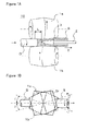
- Figures 1A and 1B are diagrams showing an example of the schematic construction of a piercing-rolling mill.
- Figure 1A is a side view and Figure 1B is a plan view.
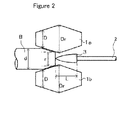
- Figure 2 is a diagram showing an approximate positional relationship among the piercer roll, the piercer plug, and the billet. The illustration of the piercer plug is omitted in Figure 1B , and for the sake of simplicity, the feed angle and toe angle of a pair of piercer rolls are set at 0 in Figure 1B .
- a piercing-rolling mill 10 is provided with a pair of piercer rolls 1a, 1b and a bullet-like piercer plug 3 whose rear end is supported by a mandrel 2.
- the pair of piercer rolls 1a, 1b are set in such a manner that the axial directions thereof are parallel to each other as viewed from the side or cross at a prescribed toe angle (in Figure 1A , only the case where the piercer rolls are set parallel to each other is shown).
- the piercer rolls are disposed in such a manner that the two are inclined at a feed angle ⁇ in directions reverse to each other as viewed from the plane and are configured to rotate in the same direction.
- the piercer plug 3 is disposed between the pair of piercer rolls 1a, 1b.
- the billet B is fed to between the pair of piercer rolls 1a and 1b.
- the force with which the billet B is rotated by the frictional force of the piercer rolls 1a, 1b and the force with which the billet B is moved forward in the axial direction act simultaneously on the billet B.
- a compressive stress and a tensile stress act alternately continuously on the central part of the billet B (the rotary forging effect)and an opening becomes tend to be formed.
- the speed of the entry of the billet B into the piercer rolls 1a, 1b is slow or the entry stops although the billet B is gripped by the piercer rolls 1a, 1b and abuts against the piercer plug 3, and the rolling load of the piercer rolls 1a, 1b increases only gently after the billet B abuts against the piercer plug 3.
- this fault is called a head jam fault.
- Examples of manufacturing conditions for preventing the occurrence of such faults at the start of piercing-rolling include increasing the draft rate, which expresses the degree of gripping by the piercer rolls 1a, 1b. However, if the draft rate is made too high, an inner surface shell flaw (a flaw occurring on the inner surface of the shell) may occur.
- Examples of manufacturing conditions for preventing the occurrence of faults at the start of piercing-rolling include increasing the coefficient of friction with the billet B by applying an antislipping agent to the surfaces of the piercer rolls 1a, 1b.
- an outer surface shell flaw (a flaw occurring on the outer surface of the shell) may occur due to the roughness of the piercer roll surface, and operation troubles may occur due to, for example, the entry of the antislipping agent into the bearings of the driving device (not shown) which rotates the piercer rolls 1a, 1b.
- the appropriate range of the draft rate is very narrow and, therefore, it is difficult to avoid faults in piercing-rolling.
- the rolling condition changes according to the condition of rough piercer roll surfaces and the like and, therefore, it is difficult to avoid faults in piercing-rolling.
- the present invention was made in order to solve such problems with conventional techniques, and the object thereof is to provide a method of detecting a fault which ensures high-accuracy detection of a fault in piercing-rolling.
- the present inventors studied a method of detecting a fault in piercing-rolling with high accuracy using various parameters obtained in piercing-rolling. As a result, they obtained the finding that it is possible to perform the detection of a fault in piercing-rolling with high accuracy by using both a rolling load parameter corresponding to a rolling load (a load applied to the piercer rolls) and a thrust load parameter corresponding to a thrust load (a load applied to the piercer plug).
- the rolling load parameter corresponding to a rolling load is a parameter having a correlation to the rolling load, and is, for example, the current value of motors driving the piercer rolls and the rolling load itself.
- the thrust load parameter corresponding to a thrust load is a parameter having a correlation to the thrust load and is, for example, the thrust load itself.
- the present invention has been achieved based on the above finding of the present inventors. That is, in order to solve the above-described problems, the present invention provides a method of detecting a fault in piercing-rolling when a billet is piercing-rolled using piercer rolls and a piercer plug, the method comprising: measuring a rolling load parameter corresponding to the rolling load of the piercer rolls and a thrust load parameter corresponding to the thrust load of the piercer plug; and detecting a fault in piercing-rolling on the basis of a measured value of the rolling load parameter and a measured value of the thrust load parameter.
- the accuracy of detection of a fault in piercing-rolling is high because a rolling load parameter and a thrust load parameter are measured and a fault in piercing-rolling is detected on the basis of both a measured value of the rolling load parameter and a measured value of the thrust load parameter.
- a fault in piercing-rolling has occurred in the case where the measured value of the thrust load parameter does not exceed a first threshold value of thrust, after the billet is gripped by the piercer rolls, by the time a first prescribed time elapses after the measured value of the rolling load parameter exceeds for the first time a first threshold value of rolling.
- the first threshold value of rolling used here is a first threshold value related to the rolling load parameter and is a threshold value for making a judgment as to whether the billet has come into contact with the piercer rolls.
- the first threshold value of thrust used here is a first threshold value related to the thrust load parameter and is a threshold value for making a judgment as to whether the leading end of the billet has abutted against the piercer plug.
- this preferable method it is judged that the billet has come into contact with the piercer rolls when the measured value of the rolling load parameter exceeds for the first time a first threshold value of rolling, which is fixed beforehand, and it is judged that the leading end of the billet has abutted against the piercer plug when the measured value of the thrust load parameter exceeds a first threshold value of thrust. Therefore, it is possible to judge with high accuracy that a slippage fault has occurred in the case where the measured value of the thrust load parameter does not exceed a first threshold value of thrust, by the time a first prescribed time elapses after the measured value of the rolling load parameter exceeds for the first time a first threshold value of rolling.
- a fault in piercing-rolling has occurred in the case where the measured value of the rolling load parameter does not exceed a second threshold value of rolling, after the billet is gripped by the piercer rolls, by the time a second prescribed time elapses after the measured value of the thrust load parameter exceeds for the first time a second threshold value of thrust.
- the second threshold value of thrust used here is a second threshold value related to the thrust load parameter and is a threshold value for making a judgment as to whether the leading end of the billet has come into contact with the piercer plug as with the first threshold value of thrust. Therefore, the same value as the first threshold value of thrust can be used.
- the second threshold value of rolling is a second threshold value related to the rolling load parameter and is a threshold value for making a judgment as to whether the billet is being normally rolled by the piercer rolls and the piercer plug after the leading end of the billet abuts against the piercer plug.
- this preferable method it is judged that the billet has abutted against the piercer plug when the measured value of the thrust load parameter exceeds for the first time a second threshold value of thrust, and it is judged that the billet is being normally rolled by the piercer rolls and the piercer plug when the measured value of the rolling load parameter exceeds the second threshold value of rolling. Therefore, it is possible to judge with high accuracy that a head jam fault has occurred in the case where the measured value of the rolling load parameter does not exceed a second threshold value of rolling, by the time a second prescribed time elapses after the measured value of the thrust load parameter exceeds for the first time a second threshold value of thrust.
- the present invention provides a method of producing a seamless pipe or tube by using piercing-rolling, comprising the steps of: detecting a fault in piercing-rolling by any of the above-described methods; and improving conditions in piercing-rolling when the fault is detected.
- conditions in piercing-rolling is improved when a fault in piercing-rolling is detected, therefore, it is possible to produce a seamless pipe or tube freely from a fault in piercing-rolling.
- the accuracy of detection of a fault in piercing-rolling is high because a rolling load parameter and a thrust load parameter are measured and a fault in piercing-rolling is detected on the basis of both a measured value of the rolling load parameter and a measured value of the thrust load parameter.
- FIG. 3 is a schematic bloc diagram showing a piercing-rolling mill 10 in which the method of detecting a fault in piercing-rolling of the present embodiment is used.
- the piercing-rolling mill 10 is provided with a rolling load sensor 4, a thrust load sensor 5, a control device 6, and an information device 7 in addition to the components described in Figures 1A and 1B .
- the rolling load sensor 4 which is, for example, a load cell, measures the rolling load of the piercer rolls 1a, 1b and transmits an electrical signal corresponding to a measured value of rolling load to the control device 6.
- the thrust load sensor 5 which is, for example, a load cell, measures the thrust load of the piercer plug 3 and transmits an electrical signal corresponding to a measured value of thrust load to the control device 6.
- the control device 6 detects a fault in piercing-rolling on the basis of electrical signals from the rolling load sensor 4 and the thrust load sensor 5.
- the information device 7 provides information about the occurrence of a fault in piercing-rolling by a signal from the control device 6.
- the information device 7 is, for example, a display screen of liquid crystal and the like, and a buzzer which sounds.
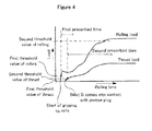
- Figure 4 shows changes in a rolling load and a thrust load at the start of piercing-rolling.
- a billet B is fed to between a pair of piercer rolls 1a, 1b and abuts against a piercer plug 3 within a prescribed period of time after the billet B is gripped by the piercer rolls 1a, 1b. It is judged that a slippage fault has occurred when the billet B does not abut against the piercer plug 3 within a prescribed period of time after being gripped by the piercer rolls 1a, 1b.
- the judgment is made as follows.
- the rolling load sensor 4 is measuring the rolling load of the piercer rolls 1a, 1b and transmits an electrical signal corresponding to a measured value of rolling load to the control device 6.
- a first threshold value of rolling is fixed beforehand. When the measured value of rolling load exceeds for the first time the first threshold value of rolling (the measured value of rolling load > the first threshold value of rolling), the control device 6 judges that the billet B has been gripped by the piercer rolls 1a, 1b.
- the first threshold value of rolling is a threshold value for making a judgment as to whether the billet B has been gripped by the piercer rolls 1a, 1b and is fixed by a prior investigation so that the control device 6 does not make a wrong judgment due to noise that the billet B has been gripped by the piercer rolls 1a, 1b although in reality the billet B was not gripped.
- the control device 6 judges that the billet B has been gripped by the piercer rolls 1a, 1b, the control device 6 starts counting the first prescribed time.
- the first threshold value of thrust is a threshold value for making a judgment as to whether the leading end of the billet B has abutted against the piercer plug 3 and is fixed by a prior investigation so that the control device 6 does not make a wrong judgment due to noise that the leading end of the billet B has abutted against the piercer plug 3 although in reality the billet B did not abut.
- the first prescribed time is fixed to make a judgment as to whether a slippage fault has occurred and is fixed from the period of time until the leading end of the billet B abuts against the piercer plug 3 after the billet B is gripped by the piercer rolls 1a, 1b in the case where a slippage fault did not occur.
- control device 6 judges that a slippage fault has occurred, the control device 6 causes the information device 7 to provide information on the occurrence of the slippage fault.
- the accuracy of detection of a fault in piercing-rolling is high because as described above, a rolling load parameter and a thrust load parameter are measured and a fault in piercing-rolling is detected on the basis of both a measured value of the rolling load parameter and a measured value of the thrust load parameter.
- the occurrence of, in particular, a slippage fault can be detected with high accuracy.
- the thrust load of the piercer plug 3 increases when the leading end of the billet B abuts against the piercer plug 3 after the billet B is gripped by the piercer rolls 1a, 1b.
- the thrust load sensor 5 is measuring the thrust load of the piercer plug 3 and transmits an electrical signal corresponding to a measured value of thrust load to the control device 6.
- a second threshold value of thrust is set in the control device 6. When the measured value of thrust load exceeds for the first time the second threshold value of thrust (the measured value of thrust load > the second threshold value of thrust), the control device 6 judges that the leading end of the billet B has abutted against the piercer plug 3.
- the second threshold value of thrust is a threshold value for making a judgment as to whether the leading end of the billet B has abutted against the piercer plug 3 and is fixed by a prior investigation so that the control device 6 does not make a wrong judgment due to noise that the leading end of the billet B has abutted against the piercer plug 3 although in reality the billet B did not abut.
- the second threshold value of thrust is a threshold value for making a judgment as to whether the leading end of the billet B has abutted against the piercer plug 3, the same value as the first threshold value of thrust can be used.
- the second prescribed time is a time for making a judgment as to whether the rolling load is increasing normally and is fixed to be the same time as the time required until the leading end of the hollow shell S reaches the position of the rear end of the piercer plug 3 after the leading end of the billet B abuts against the piercer plug 3, or a time shorter than this time.
- the second prescribed time and the second threshold value are fixed, for example, as follows.
- the second prescribed time is defined as the time required until the leading end of the hollow shell S reaches the position of the rear end of the piercer plug 3 after the leading end of the billet B abuts against the piercer plug 3 in the condition in which normal piercing-rolling is being performed.
- the second threshold value of rolling is a threshold value for making a judgment as to whether the billet B is being normally rolled by the piercer rolls 1a, 1b and the piercer plug 3 after the leading end of the billet B abuts against the piercer plug 3.
- the second threshold value of rolling is set at 90% of rolling load occurring when the leading end of the hollow shell S reaches the position of the rear end of the piercer plug 3 in the condition in which normal piercing-rolling is being performed, and the second threshold value of rolling is fixed by a prior investigation. Therefore, in usual cases, the second threshold value of rolling becomes a value larger that the first threshold value of rolling.
- control device 6 judges that a head jam fault has occurred, the control device 6 causes the information device 7 to provide information on the occurrence of the head jam fault.
- the occurrence of head jam fault can be detected with high accuracy.
- This producing method of a seamless pipe or tube includes a step of detecting a fault in piercing-rolling and a step of improving conditions in piercing-rolling when this fault is detected.
- a detection method of a slippage fault and a detection method of a head jam fault is carried out.
- the contents described below are carried out.
- the opening of the piercer rolls 1a, 1b is increased for a billet B which is being piercing-rolled, and similarly the opening of the piercer rolls 1a, 1b is increased for the billets B which are to be piercing-rolled after the billet B in question.
- the opening of the piercer rolls 1a, 1b is reduced for the billet B which is being piercing-rolled, whereas in the case of a billet B made of a high-alloy steel, an antislipping agent is applied to the piercer rolls 1a, 1b.
- both of the detection methods may be carried out. If the opening of the piercer rolls 1a, 1b is made too large when a slippage fault is detected, a head jam fault may occur, whereas if the opening of the piercer rolls 1a, 1b is made too small when a head jam fault is detected, a slippage fault may occur. Therefore, both the detection method of a slippage fault and the detection method of a head jam fault are carried out and the opening between the piercer rolls 1a and 1b is adjusted so that neither a slippage fault nor a head jam fault occurs, whereby it is possible to make adjustments to an appropriate opening.
- the present invention is not limited to the configuration of the above-described embodiment, and various modifications are possible so long as the gist of the present invention is not changed thereby.
- the second threshold value of rolling is set at 90% of rolling load occurring when the leading end of the hollow shell S reaches the position of the rear end of the piercer plug 3 in the condition in which normal piercing-rolling is being performed
- the ratio of the second threshold value of rolling to the above-described rolling load can be fixed in an arbitrary manner so long as a head jam fault can be detected.
Landscapes
- Engineering & Computer Science (AREA)
- Mechanical Engineering (AREA)
- Control Of Metal Rolling (AREA)
- Testing Of Devices, Machine Parts, Or Other Structures Thereof (AREA)
Abstract
Description
- The present invention relates to a method of detecting a fault in piercing-rolling occurring during the piercing-rolling of a billet using piercer rolls and a method of producing a seamless pipe or tube. Specifically, the present invention relates to a method of detecting a fault in piercing-rolling which enables a fault in piercing-rolling to be easily detected and a method of producing a seamless pipe or tube including a step of detecting a fault by this method.
- In the production of seamless tube by the Mannesmann-mandrel mill process, first, a billet, which is a starting material, is heated to 1200 to 1260°C in a heating furnace and after that, in the piercing-rolling process a hollow shell is produced by performing piercing-rolling using a piercer plug and the piercer rolls of a piercing-rolling mill. Next, a mandrel bar is inserted along the inner surface of the above-described hollow shell and elongation rolling is performed on a mandrel mill usually consisting of 5 to 8 stands by constraining the outer surface with grooved rolling rolls, whereby the thickness is reduced to a prescribed wall thickness and a material pipe or tube is produced. After that, the mandrel bar is extracted from the material pipe or tube and this material pipe or tube is sized on a sizing mill to a prescribed outside diameter to obtain a seamless pipe or tube as a product.
-
Figures 1A and 1B are diagrams showing an example of the schematic construction of a piercing-rolling mill.Figure 1A is a side view andFigure 1B is a plan view.Figure 2 is a diagram showing an approximate positional relationship among the piercer roll, the piercer plug, and the billet. The illustration of the piercer plug is omitted inFigure 1B , and for the sake of simplicity, the feed angle and toe angle of a pair of piercer rolls are set at 0 inFigure 1B . As shown inFigures 1A and 1B , a piercing-rollingmill 10 is provided with a pair ofpiercer rolls like piercer plug 3 whose rear end is supported by a mandrel 2. The pair ofpiercer rolls Figure 1A , only the case where the piercer rolls are set parallel to each other is shown). On the other hand, the piercer rolls are disposed in such a manner that the two are inclined at a feed angle θ in directions reverse to each other as viewed from the plane and are configured to rotate in the same direction. Thepiercer plug 3 is disposed between the pair ofpiercer rolls - In order to piercing-rolling a solid billet B using the piercing-rolling
mill 10 having this configuration, first, the billet B is fed to between the pair ofpiercer rolls piercer rolls piercer rolls piercer plug 3, a compressive stress and a tensile stress act alternately continuously on the central part of the billet B (the rotary forging effect)and an opening becomes tend to be formed. When the billet B abuts against thepiercer plug 3, a hole is made in the central part of the billet B and the billet B is thereafter subjected to wall-thickness working between thepiercer rolls piercer plug 3, whereby a hollow shell S is obtained. - In such piercing-rolling, many faults occur at the start of rolling when the billet B is gripped by the
piercer rolls mill 10. There are mainly the following two kinds of faults as faults occurring in piercing-rolling at the start of rolling.
In one fault, a fed billet B is not gripped by thepiercer rolls piercer plug 3 although the billet B comes into contact with thepiercer rolls
In another fault, the speed of the entry of the billet B into thepiercer rolls piercer rolls piercer plug 3, and the rolling load of thepiercer rolls piercer plug 3. Hereinafter, this fault is called a head jam fault. - Examples of manufacturing conditions for preventing the occurrence of such faults at the start of piercing-rolling include increasing the draft rate, which expresses the degree of gripping by the
piercer rolls
The draft rate is defined as follows (seeFigure 2 ):
where d is the outside diameter of the billet, and r is the gap between thepiercer roll 1a and thepiercer roll 1b at the place where the leading end of the billet abuts against thepiercer plug 3. - Examples of manufacturing conditions for preventing the occurrence of faults at the start of piercing-rolling include increasing the coefficient of friction with the billet B by applying an antislipping agent to the surfaces of the
piercer rolls piercer rolls - It is desirable to increase the opening of the
piercer rolls piercer rolls piercer rolls - However, for example, in the case where the billet B is made of a high-alloy steel containing not less than 2 mass% of Cr, the appropriate range of the draft rate is very narrow and, therefore, it is difficult to avoid faults in piercing-rolling. Also in the case where the billet B is made of a carbon steel, the rolling condition changes according to the condition of rough piercer roll surfaces and the like and, therefore, it is difficult to avoid faults in piercing-rolling.
- If such faults in piercing-rolling occur, in the worst case piercing-rolling is stopped and all billets B present in the production line from the heating furnace to the piercing-rolling
mill 10 must be taken out of the line, causing great damage. For this reason, in the case where a fault in piercing-rolling occurred, it is desirable to immediately detect the occurrence of the fault and to take measures.
However, the detection of these faults in piercing-rolling is visually carried out by skilled workers and is influenced by the skill of the workers, posing the problem that the accuracy of detection is low. - There are also known methods of detecting a fault in piercing-rolling which involve making a judgment that a slip has occurred between the piercer rolls and the billet and detecting a fault in piercing-rolling if during piercing-rolling the current value of motors driving the piercer rolls becomes lower than a prescribed threshold value (refer to
Patent Literature 1, for example).
However, with this detection method, it is impossible to detect faults at the start of piercing-rolling as described above. - [Patent Literature 1]
JP10-180311 - The present invention was made in order to solve such problems with conventional techniques, and the object thereof is to provide a method of detecting a fault which ensures high-accuracy detection of a fault in piercing-rolling.
- In order to solve the above-described problems, the present inventors studied a method of detecting a fault in piercing-rolling with high accuracy using various parameters obtained in piercing-rolling. As a result, they obtained the finding that it is possible to perform the detection of a fault in piercing-rolling with high accuracy by using both a rolling load parameter corresponding to a rolling load (a load applied to the piercer rolls) and a thrust load parameter corresponding to a thrust load (a load applied to the piercer plug).
The rolling load parameter corresponding to a rolling load is a parameter having a correlation to the rolling load, and is, for example, the current value of motors driving the piercer rolls and the rolling load itself. The thrust load parameter corresponding to a thrust load is a parameter having a correlation to the thrust load and is, for example, the thrust load itself. - The present invention has been achieved based on the above finding of the present inventors. That is, in order to solve the above-described problems, the present invention provides a method of detecting a fault in piercing-rolling when a billet is piercing-rolled using piercer rolls and a piercer plug, the method comprising: measuring a rolling load parameter corresponding to the rolling load of the piercer rolls and a thrust load parameter corresponding to the thrust load of the piercer plug; and detecting a fault in piercing-rolling on the basis of a measured value of the rolling load parameter and a measured value of the thrust load parameter.
- According to the present invention, the accuracy of detection of a fault in piercing-rolling is high because a rolling load parameter and a thrust load parameter are measured and a fault in piercing-rolling is detected on the basis of both a measured value of the rolling load parameter and a measured value of the thrust load parameter.
- Preferably, it is judged that a fault (concretely a slippage fault) in piercing-rolling has occurred in the case where the measured value of the thrust load parameter does not exceed a first threshold value of thrust, after the billet is gripped by the piercer rolls, by the time a first prescribed time elapses after the measured value of the rolling load parameter exceeds for the first time a first threshold value of rolling.
The first threshold value of rolling used here is a first threshold value related to the rolling load parameter and is a threshold value for making a judgment as to whether the billet has come into contact with the piercer rolls.
The first threshold value of thrust used here is a first threshold value related to the thrust load parameter and is a threshold value for making a judgment as to whether the leading end of the billet has abutted against the piercer plug. - According to this preferable method, it is judged that the billet has come into contact with the piercer rolls when the measured value of the rolling load parameter exceeds for the first time a first threshold value of rolling, which is fixed beforehand, and it is judged that the leading end of the billet has abutted against the piercer plug when the measured value of the thrust load parameter exceeds a first threshold value of thrust.
Therefore, it is possible to judge with high accuracy that a slippage fault has occurred in the case where the measured value of the thrust load parameter does not exceed a first threshold value of thrust, by the time a first prescribed time elapses after the measured value of the rolling load parameter exceeds for the first time a first threshold value of rolling. - Preferably, it is judged that a fault (concretely a head jam fault) in piercing-rolling has occurred in the case where the measured value of the rolling load parameter does not exceed a second threshold value of rolling, after the billet is gripped by the piercer rolls, by the time a second prescribed time elapses after the measured value of the thrust load parameter exceeds for the first time a second threshold value of thrust.
The second threshold value of thrust used here is a second threshold value related to the thrust load parameter and is a threshold value for making a judgment as to whether the leading end of the billet has come into contact with the piercer plug as with the first threshold value of thrust. Therefore, the same value as the first threshold value of thrust can be used. However, a value different from the first threshold value of thrust may be used so long as this value is in the range in which the purpose of making a judgment as to whether the leading end of the billet has abutted against the piercer plug is accomplished.
The second threshold value of rolling is a second threshold value related to the rolling load parameter and is a threshold value for making a judgment as to whether the billet is being normally rolled by the piercer rolls and the piercer plug after the leading end of the billet abuts against the piercer plug. - According to this preferable method, it is judged that the billet has abutted against the piercer plug when the measured value of the thrust load parameter exceeds for the first time a second threshold value of thrust, and it is judged that the billet is being normally rolled by the piercer rolls and the piercer plug when the measured value of the rolling load parameter exceeds the second threshold value of rolling.
Therefore, it is possible to judge with high accuracy that a head jam fault has occurred in the case where the measured value of the rolling load parameter does not exceed a second threshold value of rolling, by the time a second prescribed time elapses after the measured value of the thrust load parameter exceeds for the first time a second threshold value of thrust. - Also, the present invention provides a method of producing a seamless pipe or tube by using piercing-rolling, comprising the steps of: detecting a fault in piercing-rolling by any of the above-described methods; and improving conditions in piercing-rolling when the fault is detected.
- According to the present invention, conditions in piercing-rolling is improved when a fault in piercing-rolling is detected, therefore, it is possible to produce a seamless pipe or tube freely from a fault in piercing-rolling.
- According to the present invention, the accuracy of detection of a fault in piercing-rolling is high because a rolling load parameter and a thrust load parameter are measured and a fault in piercing-rolling is detected on the basis of both a measured value of the rolling load parameter and a measured value of the thrust load parameter.
-
-
Figures 1A and 1B are diagrams showing an example of the schematic construction of a conventional piercing-rolling mill.Figure 1A is a side view andFigure 1B is a plan view. -
Figure 2 is a diagram showing an approximate positional relationship among the piercer roll, the piercer plug, and the billet. -
Figure 3 is a schematic bloc diagram showing a piercing-rolling mill in which the method of detecting a fault in piercing-rolling of the present invention is used. -
Figure 4 is a diagram showing changes in a rolling load and a thrust load at the start of piercing-rolling. - Referring to the accompanying drawings as appropriate, a description will be given of the method of detecting a fault in piercing-rolling in an embodiment of the present invention.
Figure 3 is a schematic bloc diagram showing a piercing-rollingmill 10 in which the method of detecting a fault in piercing-rolling of the present embodiment is used.
The piercing-rollingmill 10 is provided with a rollingload sensor 4, a thrust load sensor 5, acontrol device 6, and aninformation device 7 in addition to the components described inFigures 1A and 1B . The rollingload sensor 4, which is, for example, a load cell, measures the rolling load of the piercer rolls 1a, 1b and transmits an electrical signal corresponding to a measured value of rolling load to thecontrol device 6. The thrust load sensor 5, which is, for example, a load cell, measures the thrust load of thepiercer plug 3 and transmits an electrical signal corresponding to a measured value of thrust load to thecontrol device 6. Thecontrol device 6 detects a fault in piercing-rolling on the basis of electrical signals from the rollingload sensor 4 and the thrust load sensor 5. Theinformation device 7 provides information about the occurrence of a fault in piercing-rolling by a signal from thecontrol device 6. Theinformation device 7 is, for example, a display screen of liquid crystal and the like, and a buzzer which sounds. - Next, a description will be given of a method of detecting a slippage fault among faults in piercing-rolling.
Figure 4 shows changes in a rolling load and a thrust load at the start of piercing-rolling.
In the case where piercing-rolling is performed normally, a billet B is fed to between a pair of piercer rolls 1a, 1b and abuts against apiercer plug 3 within a prescribed period of time after the billet B is gripped by the piercer rolls 1a, 1b. It is judged that a slippage fault has occurred when the billet B does not abut against thepiercer plug 3 within a prescribed period of time after being gripped by the piercer rolls 1a, 1b. Specifically, the judgment is made as follows.
When the billet B is fed by a transfer machine (not shown) to between the pair of piercer rolls 1a, 1b and is gripped by the piercer rolls 1a, 1b, the rolling load of the piercer rolls 1a, 1b increases. The rollingload sensor 4 is measuring the rolling load of the piercer rolls 1a, 1b and transmits an electrical signal corresponding to a measured value of rolling load to thecontrol device 6. In thecontrol device 6, a first threshold value of rolling is fixed beforehand. When the measured value of rolling load exceeds for the first time the first threshold value of rolling (the measured value of rolling load > the first threshold value of rolling), thecontrol device 6 judges that the billet B has been gripped by the piercer rolls 1a, 1b. The first threshold value of rolling is a threshold value for making a judgment as to whether the billet B has been gripped by the piercer rolls 1a, 1b and is fixed by a prior investigation so that thecontrol device 6 does not make a wrong judgment due to noise that the billet B has been gripped by the piercer rolls 1a, 1b although in reality the billet B was not gripped.
When thecontrol device 6 judges that the billet B has been gripped by the piercer rolls 1a, 1b, thecontrol device 6 starts counting the first prescribed time. - And it is judged that piercing-rolling has been started normally in the case where the measured value of thrust load transmitted from the thrust load sensor 5 exceeds the first threshold value of thrust (the measured value of thrust load > the first threshold value of thrust) by the time the first prescribed time elapses, whereas it is judged that a slippage fault has occurred in the case where the measured value of thrust load does not exceed the first threshold value of thrust.
The first threshold value of thrust is a threshold value for making a judgment as to whether the leading end of the billet B has abutted against thepiercer plug 3 and is fixed by a prior investigation so that thecontrol device 6 does not make a wrong judgment due to noise that the leading end of the billet B has abutted against thepiercer plug 3 although in reality the billet B did not abut.
The first prescribed time is fixed to make a judgment as to whether a slippage fault has occurred and is fixed from the period of time until the leading end of the billet B abuts against thepiercer plug 3 after the billet B is gripped by the piercer rolls 1a, 1b in the case where a slippage fault did not occur.
On the basis of the finding from prior investigations that a slippage fault is apt to occur in the case where the billet B does not abut against thepiercer plug 3 by the time the billet B rotates three turns after being gripped by the piercer rolls 1a, 1b, the first prescribed time is fixed, for example, as follows:
where - t1 : First prescribed time (second)
- d : Outside diameter of billet B (mm)
- D : Outside diameter of piercer rolls 1a, 1b in the position where the piercer rolls 1a, 1b gripped the billet B (mm)
- N : Number of rotations of piercer rolls 1a, 1b per second (see
Figure 2 ). - When the
control device 6 judges that a slippage fault has occurred, thecontrol device 6 causes theinformation device 7 to provide information on the occurrence of the slippage fault. - The accuracy of detection of a fault in piercing-rolling is high because as described above, a rolling load parameter and a thrust load parameter are measured and a fault in piercing-rolling is detected on the basis of both a measured value of the rolling load parameter and a measured value of the thrust load parameter.
In the above-described example, the occurrence of, in particular, a slippage fault can be detected with high accuracy. - Next, a description will be given of a method of detecting a head jam fault among faults in piercing-rolling.
In the case where piercing-rolling is performed normally, after the leading end of the billet B abuts against thepiercer plug 3, the billet B is rolled by the piercer rolls 1a, 1b and thepiercer plug 3. Therefore, the rolling load of the piercer rolls 1a, 1b increases and the rolling load becomes a maximum when the leading end of the hollow shell S reaches the position of the rear end of thepiercer plug 3. After that, the rolling load is held in the vicinity of this maximum value.
Therefore, it is judged that a head jam fault has occurred in the case where the rolling load does not exceed a prescribed value within a prescribed period of time after the billet B abuts against thepiercer plug 3. Specifically, the judgment is made as follows. - The thrust load of the
piercer plug 3 increases when the leading end of the billet B abuts against thepiercer plug 3 after the billet B is gripped by the piercer rolls 1a, 1b. The thrust load sensor 5 is measuring the thrust load of thepiercer plug 3 and transmits an electrical signal corresponding to a measured value of thrust load to thecontrol device 6. In thecontrol device 6, a second threshold value of thrust is set. When the measured value of thrust load exceeds for the first time the second threshold value of thrust (the measured value of thrust load > the second threshold value of thrust), thecontrol device 6 judges that the leading end of the billet B has abutted against thepiercer plug 3.
The second threshold value of thrust is a threshold value for making a judgment as to whether the leading end of the billet B has abutted against thepiercer plug 3 and is fixed by a prior investigation so that thecontrol device 6 does not make a wrong judgment due to noise that the leading end of the billet B has abutted against thepiercer plug 3 although in reality the billet B did not abut. Because as with the first threshold value of thrust, the second threshold value of thrust is a threshold value for making a judgment as to whether the leading end of the billet B has abutted against thepiercer plug 3, the same value as the first threshold value of thrust can be used. However, a value different from the first threshold value of thrust may be used so long as this value is in the range in which the purpose of making a judgment as to whether the leading end of the billet has abutted against the piercer plug is accomplished.
The second prescribed time is a time for making a judgment as to whether the rolling load is increasing normally and is fixed to be the same time as the time required until the leading end of the hollow shell S reaches the position of the rear end of thepiercer plug 3 after the leading end of the billet B abuts against thepiercer plug 3, or a time shorter than this time.
When thecontrol device 6 judges that the billet B has abutted against thepiercer plug 3, thecontrol device 6 starts counting the second prescribed time. - And it is judged that the billet B is being rolled normally by the piercer rolls 1a, 1b and the
piercer plug 3 in the case where the measured value of rolling load transmitted from the rollingload sensor 4 exceeds the second threshold value of rolling (the measured value of rolling load > the second threshold value of rolling) by the time the second prescribed time elapses, whereas it is judged that a head jam fault has occurred in the case where the rolling load does not exceed the second threshold value of rolling. - The second prescribed time and the second threshold value are fixed, for example, as follows.
The second prescribed time is defined as the time required until the leading end of the hollow shell S reaches the position of the rear end of thepiercer plug 3 after the leading end of the billet B abuts against thepiercer plug 3 in the condition in which normal piercing-rolling is being performed. The second threshold value of rolling is a threshold value for making a judgment as to whether the billet B is being normally rolled by the piercer rolls 1a, 1b and thepiercer plug 3 after the leading end of the billet B abuts against thepiercer plug 3. The second threshold value of rolling is set at 90% of rolling load occurring when the leading end of the hollow shell S reaches the position of the rear end of thepiercer plug 3 in the condition in which normal piercing-rolling is being performed, and the second threshold value of rolling is fixed by a prior investigation. Therefore, in usual cases, the second threshold value of rolling becomes a value larger that the first threshold value of rolling.
Specifically, the second prescribed time is fixed, for example, as follows: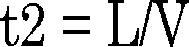
where, - t2 : Second prescribed time (second)
- L : Length of
piercer plug 3 - V : Rolling speed at the leading end of hollow shell S (see
Figures 1A and 1B andFigure 2 ). - When the
control device 6 judges that a head jam fault has occurred, thecontrol device 6 causes theinformation device 7 to provide information on the occurrence of the head jam fault. - As described above, the occurrence of head jam fault can be detected with high accuracy.
- Next, a description will be given of a method of producing a seamless pipe or tube in which the above-described method of detecting a fault in piercing-rolling is used. This producing method of a seamless pipe or tube includes a step of detecting a fault in piercing-rolling and a step of improving conditions in piercing-rolling when this fault is detected.
In the step of detecting a fault in piercing-rolling, either or both of a detection method of a slippage fault and a detection method of a head jam fault is carried out.
And in the step of improving conditions in piercing-rolling, for example, the contents described below are carried out.
When a slippage fault has occurred, the opening of the piercer rolls 1a, 1b is increased for a billet B which is being piercing-rolled, and similarly the opening of the piercer rolls 1a, 1b is increased for the billets B which are to be piercing-rolled after the billet B in question.
When a head jam fault has occurred, in the case of a billet B made of an ordinary steel, the opening of the piercer rolls 1a, 1b is reduced for the billet B which is being piercing-rolled, whereas in the case of a billet B made of a high-alloy steel, an antislipping agent is applied to the piercer rolls 1a, 1b. And the same thing is carried out also for the billets B to be piercing-rolled after the billet B in question.
Further, when a slippage fault or a head jam fault has occurred, a draft rate can be corrected for the billets B to be piercing-rolled after the billet B in question.
As described above, when a fault in piercing-rolling is detected, conditions in piercing-rolling are improved, whereby a seamless pipe or tube can be produced freely from faults in piercing-rolling. - For the above-described detection method of a slippage fault and detection method of a head jam fault, either or both of the detection methods may be carried out. If the opening of the piercer rolls 1a, 1b is made too large when a slippage fault is detected, a head jam fault may occur, whereas if the opening of the piercer rolls 1a, 1b is made too small when a head jam fault is detected, a slippage fault may occur. Therefore, both the detection method of a slippage fault and the detection method of a head jam fault are carried out and the opening between the piercer rolls 1a and 1b is adjusted so that neither a slippage fault nor a head jam fault occurs, whereby it is possible to make adjustments to an appropriate opening.
- The present invention is not limited to the configuration of the above-described embodiment, and various modifications are possible so long as the gist of the present invention is not changed thereby. For example, although in the above-described embodiment, the second threshold value of rolling is set at 90% of rolling load occurring when the leading end of the hollow shell S reaches the position of the rear end of the
piercer plug 3 in the condition in which normal piercing-rolling is being performed, the ratio of the second threshold value of rolling to the above-described rolling load can be fixed in an arbitrary manner so long as a head jam fault can be detected. -
- 1a, 1b ... Piercer roll
- 3 ... Piercer plug
- B ... Billet

Dr : Maximum diameter of piercer rolls 1a, 1b (mm)
N : Number of rotations of piercer rolls 1a, 1b per second (see
The peripheral speed of the piercer rolls 1a, 1b in the place where the outside diameter of the piercer rolls 1a, 1b is a maximum is calculated, and V is set at 50% of the component constituting this peripheral speed in the axial direction of the hollow shell. In the above-described formulae, the ratio of V to the component constituting the peripheral speed of the piercer rolls 1a, 1b in the axial direction of the hollow shell can be changed according to rolling conditions.
Claims (4)
- A method of detecting a fault in piercing-rolling when a billet is piercing-rolled using piercer rolls and a piercer plug, the method comprising:measuring a rolling load parameter corresponding to the rolling load of the piercer rolls and a thrust load parameter corresponding to the thrust load of the piercer plug; anddetecting a fault in piercing-rolling on the basis of a measured value of the rolling load parameter and a measured value of the thrust load parameter.
- The method of detecting a fault in piercing-rolling according to claim 1, wherein it is judged that a fault in piercing-rolling has occurred in the case where the measured value of the thrust load parameter does not exceed a first threshold value of thrust, after the billet is gripped by the piercer rolls, by the time a first prescribed time elapses after the measured value of the rolling load parameter exceeds for the first time a first threshold value of rolling.
- The method of detecting a fault in piercing-rolling according to claim 1, wherein it is judged that a fault in piercing-rolling has occurred in the case where the measured value of the rolling load parameter does not exceed a second threshold value of rolling, after the billet is gripped by the piercer rolls, by the time a second prescribed time elapses after the measured value of the thrust load parameter exceeds for the first time a second threshold value of thrust.
- A method of producing a seamless pipe or tube by using piercing-rolling, comprising the steps of:detecting a fault in piercing-rolling by the method according to any one of claims 1 to 3; andimproving conditions in piercing-rolling when the fault is detected.
Applications Claiming Priority (2)
| Application Number | Priority Date | Filing Date | Title |
|---|---|---|---|
| JP2010246168A JP4947450B2 (en) | 2010-11-02 | 2010-11-02 | Defective detection method for piercing and rolling, and seamless pipe manufacturing method |
| PCT/JP2011/075148 WO2012060358A1 (en) | 2010-11-02 | 2011-11-01 | Method of detecting defects in rotary piercing, seamless pipe manufacturing method |
Publications (3)
| Publication Number | Publication Date |
|---|---|
| EP2636462A1 true EP2636462A1 (en) | 2013-09-11 |
| EP2636462A4 EP2636462A4 (en) | 2015-07-29 |
| EP2636462B1 EP2636462B1 (en) | 2017-01-11 |
Family
ID=46024472
Family Applications (1)
| Application Number | Title | Priority Date | Filing Date |
|---|---|---|---|
| EP11838008.8A Not-in-force EP2636462B1 (en) | 2010-11-02 | 2011-11-01 | Method of detecting defects in rotary piercing, seamless pipe manufacturing method |
Country Status (6)
| Country | Link |
|---|---|
| US (1) | US9333545B2 (en) |
| EP (1) | EP2636462B1 (en) |
| JP (1) | JP4947450B2 (en) |
| CN (1) | CN103282135B (en) |
| BR (1) | BR112013010811A2 (en) |
| WO (1) | WO2012060358A1 (en) |
Families Citing this family (4)
| Publication number | Priority date | Publication date | Assignee | Title |
|---|---|---|---|---|
| ES2968826T3 (en) * | 2017-12-28 | 2024-05-14 | Waste Eng Sagl | Organic waste treatment machine and related control procedure |
| CN111889523B (en) * | 2019-05-05 | 2022-07-08 | 中冶赛迪重庆信息技术有限公司 | Seamless steel tube wall thickness control method |
| CN111069298B (en) * | 2019-12-19 | 2021-10-08 | 太原重工股份有限公司 | Digital control system and method for puncher |
| CN119327879B (en) * | 2023-07-20 | 2025-12-16 | 宝山钢铁股份有限公司 | A method for determining the temperature of an annular furnace in the low-temperature rolling process of seamless steel pipes |
Family Cites Families (18)
| Publication number | Priority date | Publication date | Assignee | Title |
|---|---|---|---|---|
| US4006618A (en) * | 1974-07-23 | 1977-02-08 | Samon Yanagimoto | Method of producing seamless steel tube |
| US4190887A (en) * | 1975-08-22 | 1980-02-26 | Nippon Steel Corporation | Press roll piercing method |
| JPS5970424A (en) * | 1982-10-13 | 1984-04-20 | Toshiba Corp | Detecting device for biting of tube material |
| JPS5976609A (en) * | 1982-10-22 | 1984-05-01 | Toshiba Corp | Method for controlling tension of mandrel bar in piercing mill |
| JPS59118206A (en) * | 1982-12-25 | 1984-07-07 | Kawasaki Steel Corp | Method for detecting generation of thickness deviation in skew rolling mill |
| JP2697144B2 (en) * | 1989-06-08 | 1998-01-14 | 住友金属工業株式会社 | Rolling method of seamless pipe |
| CN1018336B (en) * | 1990-07-19 | 1992-09-23 | 鞍山钢铁公司 | Dynamic stable two-roller horizontal hot-rolled pipe puncher |
| JPH10180311A (en) | 1996-12-24 | 1998-07-07 | Sanyo Special Steel Co Ltd | How to prevent piercer roll slip |
| JP2000000605A (en) * | 1998-06-15 | 2000-01-07 | Nkk Corp | Seamless pipe and method of manufacturing the same |
| JP2000246311A (en) * | 1999-03-03 | 2000-09-12 | Nkk Corp | Seamless pipe manufacturing method for difficult-to-process materials or as cast round slabs |
| JP2000334505A (en) * | 1999-05-24 | 2000-12-05 | Nkk Corp | Manufacturing method of seamless steel pipe |
| JP2000334506A (en) * | 1999-05-24 | 2000-12-05 | Nkk Corp | Manufacturing method of seamless steel pipe |
| JP3425718B2 (en) * | 1999-12-06 | 2003-07-14 | Jfeエンジニアリング株式会社 | Seamless pipe manufacturing method |
| JP3503552B2 (en) * | 1999-12-06 | 2004-03-08 | Jfeスチール株式会社 | Seamless pipe manufacturing method |
| JP3785930B2 (en) * | 2000-12-22 | 2006-06-14 | 住友金属工業株式会社 | Slip detection device for inclined rolling mill with disk roll |
| JP2006297400A (en) * | 2005-04-15 | 2006-11-02 | Sanyo Special Steel Co Ltd | Drilling method for seamless steel pipe |
| EP2002904B1 (en) * | 2006-03-31 | 2013-06-05 | Nippon Steel & Sumitomo Metal Corporation | Method of manufacturing seamless pipe |
| JP4826949B2 (en) * | 2006-09-11 | 2011-11-30 | 住友金属工業株式会社 | Seamless pipe manufacturing status monitoring apparatus and method, and seamless pipe manufacturing equipment |
-
2010
- 2010-11-02 JP JP2010246168A patent/JP4947450B2/en not_active Expired - Fee Related
-
2011
- 2011-11-01 WO PCT/JP2011/075148 patent/WO2012060358A1/en not_active Ceased
- 2011-11-01 CN CN201180063948.6A patent/CN103282135B/en not_active Expired - Fee Related
- 2011-11-01 EP EP11838008.8A patent/EP2636462B1/en not_active Not-in-force
- 2011-11-01 BR BR112013010811A patent/BR112013010811A2/en not_active Application Discontinuation
- 2011-11-01 US US13/882,743 patent/US9333545B2/en active Active
Also Published As
| Publication number | Publication date |
|---|---|
| JP2012096265A (en) | 2012-05-24 |
| EP2636462B1 (en) | 2017-01-11 |
| JP4947450B2 (en) | 2012-06-06 |
| CN103282135B (en) | 2015-05-20 |
| US20130276498A1 (en) | 2013-10-24 |
| CN103282135A (en) | 2013-09-04 |
| BR112013010811A2 (en) | 2016-08-09 |
| EP2636462A4 (en) | 2015-07-29 |
| US9333545B2 (en) | 2016-05-10 |
| WO2012060358A1 (en) | 2012-05-10 |
Similar Documents
| Publication | Publication Date | Title |
|---|---|---|
| EP2656936B1 (en) | Hot rolling equipment and hot rolling method | |
| EP2080569B1 (en) | Device and method for monitoring manufacturing status of seamless pipe and seamless pipe manufacturing facility | |
| CN101410196B (en) | Manufacturing method of seamless steel pipe | |
| EP2636462B1 (en) | Method of detecting defects in rotary piercing, seamless pipe manufacturing method | |
| CN101405096B (en) | Method for manufacturing seamless pipe | |
| EP2085158A1 (en) | Mandrel mill, its operating method, and seamless pipe manufacturing method | |
| US8104316B2 (en) | Piercing mill | |
| EP2098310B1 (en) | Manufacturing method for seamless pipe | |
| US9254511B2 (en) | Method for producing seamless tube/pipe | |
| EP4108352B1 (en) | Inclined rolling equipment, method for producing seamless tube blank, and method for producing seamless steel tube | |
| JP2008229648A (en) | How to replace the plug for seamless steel pipe | |
| CN113766979A (en) | Method and apparatus for determining twist angle during rolling operation | |
| JP6102854B2 (en) | Pusher drive device and drive method for applying back pressure to billet | |
| JP2001038407A (en) | Perforation rolling method for seamless metal pipe | |
| JPH0227043B2 (en) | ||
| EP2465618A1 (en) | Apparatus for adjusting screw-down position of mill roll which constitutes three-roll type mandrel mill, and method for manufacturing seamless pipe | |
| JP2002102906A (en) | Rolling method of seamless metal pipe | |
| JPS6384721A (en) | Thickness deviation detecting method in pipe making process | |
| JPS59118206A (en) | Method for detecting generation of thickness deviation in skew rolling mill |
Legal Events
| Date | Code | Title | Description |
|---|---|---|---|
| PUAI | Public reference made under article 153(3) epc to a published international application that has entered the european phase |
Free format text: ORIGINAL CODE: 0009012 |
|
| 17P | Request for examination filed |
Effective date: 20130531 |
|
| AK | Designated contracting states |
Kind code of ref document: A1 Designated state(s): AL AT BE BG CH CY CZ DE DK EE ES FI FR GB GR HR HU IE IS IT LI LT LU LV MC MK MT NL NO PL PT RO RS SE SI SK SM TR |
|
| DAX | Request for extension of the european patent (deleted) | ||
| RA4 | Supplementary search report drawn up and despatched (corrected) |
Effective date: 20150630 |
|
| RIC1 | Information provided on ipc code assigned before grant |
Ipc: B21B 19/04 20060101AFI20150624BHEP Ipc: B21C 51/00 20060101ALI20150624BHEP |
|
| GRAP | Despatch of communication of intention to grant a patent |
Free format text: ORIGINAL CODE: EPIDOSNIGR1 |
|
| INTG | Intention to grant announced |
Effective date: 20160802 |
|
| GRAJ | Information related to disapproval of communication of intention to grant by the applicant or resumption of examination proceedings by the epo deleted |
Free format text: ORIGINAL CODE: EPIDOSDIGR1 |
|
| GRAR | Information related to intention to grant a patent recorded |
Free format text: ORIGINAL CODE: EPIDOSNIGR71 |
|
| GRAS | Grant fee paid |
Free format text: ORIGINAL CODE: EPIDOSNIGR3 |
|
| INTC | Intention to grant announced (deleted) | ||
| INTG | Intention to grant announced |
Effective date: 20161006 |
|
| GRAA | (expected) grant |
Free format text: ORIGINAL CODE: 0009210 |
|
| AK | Designated contracting states |
Kind code of ref document: B1 Designated state(s): AL AT BE BG CH CY CZ DE DK EE ES FI FR GB GR HR HU IE IS IT LI LT LU LV MC MK MT NL NO PL PT RO RS SE SI SK SM TR |
|
| REG | Reference to a national code |
Ref country code: GB Ref legal event code: FG4D |
|
| REG | Reference to a national code |
Ref country code: CH Ref legal event code: EP |
|
| REG | Reference to a national code |
Ref country code: AT Ref legal event code: REF Ref document number: 860784 Country of ref document: AT Kind code of ref document: T Effective date: 20170115 |
|
| REG | Reference to a national code |
Ref country code: IE Ref legal event code: FG4D |
|
| REG | Reference to a national code |
Ref country code: DE Ref legal event code: R096 Ref document number: 602011034368 Country of ref document: DE |
|
| REG | Reference to a national code |
Ref country code: LT Ref legal event code: MG4D |
|
| REG | Reference to a national code |
Ref country code: NL Ref legal event code: MP Effective date: 20170111 |
|
| REG | Reference to a national code |
Ref country code: AT Ref legal event code: MK05 Ref document number: 860784 Country of ref document: AT Kind code of ref document: T Effective date: 20170111 |
|
| PG25 | Lapsed in a contracting state [announced via postgrant information from national office to epo] |
Ref country code: NL Free format text: LAPSE BECAUSE OF FAILURE TO SUBMIT A TRANSLATION OF THE DESCRIPTION OR TO PAY THE FEE WITHIN THE PRESCRIBED TIME-LIMIT Effective date: 20170111 |
|
| PG25 | Lapsed in a contracting state [announced via postgrant information from national office to epo] |
Ref country code: LT Free format text: LAPSE BECAUSE OF FAILURE TO SUBMIT A TRANSLATION OF THE DESCRIPTION OR TO PAY THE FEE WITHIN THE PRESCRIBED TIME-LIMIT Effective date: 20170111 Ref country code: FI Free format text: LAPSE BECAUSE OF FAILURE TO SUBMIT A TRANSLATION OF THE DESCRIPTION OR TO PAY THE FEE WITHIN THE PRESCRIBED TIME-LIMIT Effective date: 20170111 Ref country code: GR Free format text: LAPSE BECAUSE OF FAILURE TO SUBMIT A TRANSLATION OF THE DESCRIPTION OR TO PAY THE FEE WITHIN THE PRESCRIBED TIME-LIMIT Effective date: 20170412 Ref country code: NO Free format text: LAPSE BECAUSE OF FAILURE TO SUBMIT A TRANSLATION OF THE DESCRIPTION OR TO PAY THE FEE WITHIN THE PRESCRIBED TIME-LIMIT Effective date: 20170411 Ref country code: HR Free format text: LAPSE BECAUSE OF FAILURE TO SUBMIT A TRANSLATION OF THE DESCRIPTION OR TO PAY THE FEE WITHIN THE PRESCRIBED TIME-LIMIT Effective date: 20170111 Ref country code: IS Free format text: LAPSE BECAUSE OF FAILURE TO SUBMIT A TRANSLATION OF THE DESCRIPTION OR TO PAY THE FEE WITHIN THE PRESCRIBED TIME-LIMIT Effective date: 20170511 |
|
| PG25 | Lapsed in a contracting state [announced via postgrant information from national office to epo] |
Ref country code: ES Free format text: LAPSE BECAUSE OF FAILURE TO SUBMIT A TRANSLATION OF THE DESCRIPTION OR TO PAY THE FEE WITHIN THE PRESCRIBED TIME-LIMIT Effective date: 20170111 Ref country code: LV Free format text: LAPSE BECAUSE OF FAILURE TO SUBMIT A TRANSLATION OF THE DESCRIPTION OR TO PAY THE FEE WITHIN THE PRESCRIBED TIME-LIMIT Effective date: 20170111 Ref country code: AT Free format text: LAPSE BECAUSE OF FAILURE TO SUBMIT A TRANSLATION OF THE DESCRIPTION OR TO PAY THE FEE WITHIN THE PRESCRIBED TIME-LIMIT Effective date: 20170111 Ref country code: PL Free format text: LAPSE BECAUSE OF FAILURE TO SUBMIT A TRANSLATION OF THE DESCRIPTION OR TO PAY THE FEE WITHIN THE PRESCRIBED TIME-LIMIT Effective date: 20170111 Ref country code: PT Free format text: LAPSE BECAUSE OF FAILURE TO SUBMIT A TRANSLATION OF THE DESCRIPTION OR TO PAY THE FEE WITHIN THE PRESCRIBED TIME-LIMIT Effective date: 20170511 Ref country code: RS Free format text: LAPSE BECAUSE OF FAILURE TO SUBMIT A TRANSLATION OF THE DESCRIPTION OR TO PAY THE FEE WITHIN THE PRESCRIBED TIME-LIMIT Effective date: 20170111 Ref country code: BG Free format text: LAPSE BECAUSE OF FAILURE TO SUBMIT A TRANSLATION OF THE DESCRIPTION OR TO PAY THE FEE WITHIN THE PRESCRIBED TIME-LIMIT Effective date: 20170411 Ref country code: SE Free format text: LAPSE BECAUSE OF FAILURE TO SUBMIT A TRANSLATION OF THE DESCRIPTION OR TO PAY THE FEE WITHIN THE PRESCRIBED TIME-LIMIT Effective date: 20170111 |
|
| REG | Reference to a national code |
Ref country code: DE Ref legal event code: R097 Ref document number: 602011034368 Country of ref document: DE |
|
| PG25 | Lapsed in a contracting state [announced via postgrant information from national office to epo] |
Ref country code: EE Free format text: LAPSE BECAUSE OF FAILURE TO SUBMIT A TRANSLATION OF THE DESCRIPTION OR TO PAY THE FEE WITHIN THE PRESCRIBED TIME-LIMIT Effective date: 20170111 Ref country code: CZ Free format text: LAPSE BECAUSE OF FAILURE TO SUBMIT A TRANSLATION OF THE DESCRIPTION OR TO PAY THE FEE WITHIN THE PRESCRIBED TIME-LIMIT Effective date: 20170111 Ref country code: RO Free format text: LAPSE BECAUSE OF FAILURE TO SUBMIT A TRANSLATION OF THE DESCRIPTION OR TO PAY THE FEE WITHIN THE PRESCRIBED TIME-LIMIT Effective date: 20170111 Ref country code: SK Free format text: LAPSE BECAUSE OF FAILURE TO SUBMIT A TRANSLATION OF THE DESCRIPTION OR TO PAY THE FEE WITHIN THE PRESCRIBED TIME-LIMIT Effective date: 20170111 |
|
| PLBE | No opposition filed within time limit |
Free format text: ORIGINAL CODE: 0009261 |
|
| STAA | Information on the status of an ep patent application or granted ep patent |
Free format text: STATUS: NO OPPOSITION FILED WITHIN TIME LIMIT |
|
| REG | Reference to a national code |
Ref country code: FR Ref legal event code: PLFP Year of fee payment: 7 |
|
| PG25 | Lapsed in a contracting state [announced via postgrant information from national office to epo] |
Ref country code: DK Free format text: LAPSE BECAUSE OF FAILURE TO SUBMIT A TRANSLATION OF THE DESCRIPTION OR TO PAY THE FEE WITHIN THE PRESCRIBED TIME-LIMIT Effective date: 20170111 Ref country code: SM Free format text: LAPSE BECAUSE OF FAILURE TO SUBMIT A TRANSLATION OF THE DESCRIPTION OR TO PAY THE FEE WITHIN THE PRESCRIBED TIME-LIMIT Effective date: 20170111 |
|
| 26N | No opposition filed |
Effective date: 20171012 |
|
| PG25 | Lapsed in a contracting state [announced via postgrant information from national office to epo] |
Ref country code: SI Free format text: LAPSE BECAUSE OF FAILURE TO SUBMIT A TRANSLATION OF THE DESCRIPTION OR TO PAY THE FEE WITHIN THE PRESCRIBED TIME-LIMIT Effective date: 20170111 |
|
| PG25 | Lapsed in a contracting state [announced via postgrant information from national office to epo] |
Ref country code: MC Free format text: LAPSE BECAUSE OF FAILURE TO SUBMIT A TRANSLATION OF THE DESCRIPTION OR TO PAY THE FEE WITHIN THE PRESCRIBED TIME-LIMIT Effective date: 20170111 |
|
| GBPC | Gb: european patent ceased through non-payment of renewal fee |
Effective date: 20171101 |
|
| PG25 | Lapsed in a contracting state [announced via postgrant information from national office to epo] |
Ref country code: CH Free format text: LAPSE BECAUSE OF NON-PAYMENT OF DUE FEES Effective date: 20171130 Ref country code: LI Free format text: LAPSE BECAUSE OF NON-PAYMENT OF DUE FEES Effective date: 20171130 |
|
| PG25 | Lapsed in a contracting state [announced via postgrant information from national office to epo] |
Ref country code: LU Free format text: LAPSE BECAUSE OF NON-PAYMENT OF DUE FEES Effective date: 20171101 |
|
| REG | Reference to a national code |
Ref country code: BE Ref legal event code: MM Effective date: 20171130 |
|
| REG | Reference to a national code |
Ref country code: IE Ref legal event code: MM4A |
|
| PG25 | Lapsed in a contracting state [announced via postgrant information from national office to epo] |
Ref country code: MT Free format text: LAPSE BECAUSE OF NON-PAYMENT OF DUE FEES Effective date: 20171101 |
|
| REG | Reference to a national code |
Ref country code: FR Ref legal event code: PLFP Year of fee payment: 8 |
|
| PG25 | Lapsed in a contracting state [announced via postgrant information from national office to epo] |
Ref country code: IE Free format text: LAPSE BECAUSE OF NON-PAYMENT OF DUE FEES Effective date: 20171101 |
|
| PG25 | Lapsed in a contracting state [announced via postgrant information from national office to epo] |
Ref country code: GB Free format text: LAPSE BECAUSE OF NON-PAYMENT OF DUE FEES Effective date: 20171101 Ref country code: BE Free format text: LAPSE BECAUSE OF NON-PAYMENT OF DUE FEES Effective date: 20171130 |
|
| REG | Reference to a national code |
Ref country code: DE Ref legal event code: R082 Ref document number: 602011034368 Country of ref document: DE Representative=s name: ZIMMERMANN & PARTNER PATENTANWAELTE MBB, DE Ref country code: DE Ref legal event code: R081 Ref document number: 602011034368 Country of ref document: DE Owner name: NIPPON STEEL CORPORATION, JP Free format text: FORMER OWNER: NIPPON STEEL & SUMITOMO METAL CORPORATION, TOKYO, JP |
|
| PG25 | Lapsed in a contracting state [announced via postgrant information from national office to epo] |
Ref country code: HU Free format text: LAPSE BECAUSE OF FAILURE TO SUBMIT A TRANSLATION OF THE DESCRIPTION OR TO PAY THE FEE WITHIN THE PRESCRIBED TIME-LIMIT; INVALID AB INITIO Effective date: 20111101 |
|
| PG25 | Lapsed in a contracting state [announced via postgrant information from national office to epo] |
Ref country code: CY Free format text: LAPSE BECAUSE OF NON-PAYMENT OF DUE FEES Effective date: 20170111 |
|
| PG25 | Lapsed in a contracting state [announced via postgrant information from national office to epo] |
Ref country code: MK Free format text: LAPSE BECAUSE OF FAILURE TO SUBMIT A TRANSLATION OF THE DESCRIPTION OR TO PAY THE FEE WITHIN THE PRESCRIBED TIME-LIMIT Effective date: 20170111 |
|
| PGFP | Annual fee paid to national office [announced via postgrant information from national office to epo] |
Ref country code: DE Payment date: 20191022 Year of fee payment: 9 |
|
| PGFP | Annual fee paid to national office [announced via postgrant information from national office to epo] |
Ref country code: FR Payment date: 20191015 Year of fee payment: 9 Ref country code: IT Payment date: 20191108 Year of fee payment: 9 |
|
| PG25 | Lapsed in a contracting state [announced via postgrant information from national office to epo] |
Ref country code: TR Free format text: LAPSE BECAUSE OF FAILURE TO SUBMIT A TRANSLATION OF THE DESCRIPTION OR TO PAY THE FEE WITHIN THE PRESCRIBED TIME-LIMIT Effective date: 20170111 |
|
| PG25 | Lapsed in a contracting state [announced via postgrant information from national office to epo] |
Ref country code: AL Free format text: LAPSE BECAUSE OF FAILURE TO SUBMIT A TRANSLATION OF THE DESCRIPTION OR TO PAY THE FEE WITHIN THE PRESCRIBED TIME-LIMIT Effective date: 20170111 |
|
| REG | Reference to a national code |
Ref country code: DE Ref legal event code: R119 Ref document number: 602011034368 Country of ref document: DE |
|
| PG25 | Lapsed in a contracting state [announced via postgrant information from national office to epo] |
Ref country code: FR Free format text: LAPSE BECAUSE OF NON-PAYMENT OF DUE FEES Effective date: 20201130 Ref country code: IT Free format text: LAPSE BECAUSE OF NON-PAYMENT OF DUE FEES Effective date: 20201101 |
|
| PG25 | Lapsed in a contracting state [announced via postgrant information from national office to epo] |
Ref country code: DE Free format text: LAPSE BECAUSE OF NON-PAYMENT OF DUE FEES Effective date: 20210601 |