EP2636112B1 - Cable grommet for use with a raised floor - Google Patents
Cable grommet for use with a raised floor Download PDFInfo
- Publication number
- EP2636112B1 EP2636112B1 EP11838658.0A EP11838658A EP2636112B1 EP 2636112 B1 EP2636112 B1 EP 2636112B1 EP 11838658 A EP11838658 A EP 11838658A EP 2636112 B1 EP2636112 B1 EP 2636112B1
- Authority
- EP
- European Patent Office
- Prior art keywords
- finger
- panel
- fingers
- assembly
- mounting flange
- Prior art date
- Legal status (The legal status is an assumption and is not a legal conclusion. Google has not performed a legal analysis and makes no representation as to the accuracy of the status listed.)
- Not-in-force
Links
- 125000006850 spacer group Chemical group 0.000 claims description 22
- 230000000712 assembly Effects 0.000 claims description 20
- 238000000429 assembly Methods 0.000 claims description 20
- 239000000463 material Substances 0.000 claims description 13
- 238000001816 cooling Methods 0.000 description 10
- 229920000642 polymer Polymers 0.000 description 7
- 238000007789 sealing Methods 0.000 description 5
- RNFJDJUURJAICM-UHFFFAOYSA-N 2,2,4,4,6,6-hexaphenoxy-1,3,5-triaza-2$l^{5},4$l^{5},6$l^{5}-triphosphacyclohexa-1,3,5-triene Chemical compound N=1P(OC=2C=CC=CC=2)(OC=2C=CC=CC=2)=NP(OC=2C=CC=CC=2)(OC=2C=CC=CC=2)=NP=1(OC=1C=CC=CC=1)OC1=CC=CC=C1 RNFJDJUURJAICM-UHFFFAOYSA-N 0.000 description 4
- 238000010276 construction Methods 0.000 description 4
- 239000003063 flame retardant Substances 0.000 description 4
- 238000000034 method Methods 0.000 description 4
- 230000001419 dependent effect Effects 0.000 description 3
- 239000004676 acrylonitrile butadiene styrene Substances 0.000 description 2
- 230000004888 barrier function Effects 0.000 description 2
- 230000008878 coupling Effects 0.000 description 2
- 238000010168 coupling process Methods 0.000 description 2
- 238000005859 coupling reaction Methods 0.000 description 2
- 230000007423 decrease Effects 0.000 description 2
- 229910052751 metal Inorganic materials 0.000 description 2
- 239000002184 metal Substances 0.000 description 2
- 150000002739 metals Chemical class 0.000 description 2
- 239000000203 mixture Substances 0.000 description 2
- 229920003023 plastic Polymers 0.000 description 2
- 239000004033 plastic Substances 0.000 description 2
- 239000004800 polyvinyl chloride Substances 0.000 description 2
- 229920004142 LEXAN™ Polymers 0.000 description 1
- 230000001154 acute effect Effects 0.000 description 1
- 238000004378 air conditioning Methods 0.000 description 1
- QVGXLLKOCUKJST-UHFFFAOYSA-N atomic oxygen Chemical compound [O] QVGXLLKOCUKJST-UHFFFAOYSA-N 0.000 description 1
- 238000009954 braiding Methods 0.000 description 1
- 239000004020 conductor Substances 0.000 description 1
- 238000009408 flooring Methods 0.000 description 1
- -1 for example Polymers 0.000 description 1
- 238000009434 installation Methods 0.000 description 1
- 238000009413 insulation Methods 0.000 description 1
- 239000012528 membrane Substances 0.000 description 1
- 229910052760 oxygen Inorganic materials 0.000 description 1
- 239000001301 oxygen Substances 0.000 description 1
- 239000004431 polycarbonate resin Substances 0.000 description 1
- 229920005668 polycarbonate resin Polymers 0.000 description 1
- 238000007665 sagging Methods 0.000 description 1
- 229920001169 thermoplastic Polymers 0.000 description 1
- 239000004416 thermosoftening plastic Substances 0.000 description 1
Images


Classifications
-
- H—ELECTRICITY
- H02—GENERATION; CONVERSION OR DISTRIBUTION OF ELECTRIC POWER
- H02G—INSTALLATION OF ELECTRIC CABLES OR LINES, OR OF COMBINED OPTICAL AND ELECTRIC CABLES OR LINES
- H02G3/00—Installations of electric cables or lines or protective tubing therefor in or on buildings, equivalent structures or vehicles
- H02G3/02—Details
- H02G3/08—Distribution boxes; Connection or junction boxes
- H02G3/18—Distribution boxes; Connection or junction boxes providing line outlets
- H02G3/185—Floor outlets and access cups
Definitions
- the invention relates generally to a cable grommet for use with a raised floor.
- Cooling air is often supplied to data centers and offices via ducts or plenums located under a raised floor. These same under-floor ducts or plenums may also be used for the passage of power and data cables, and openings are often provided in the raised floors to route these cables to the electrical equipment located above the floor. Unfortunately, these openings in the raised floor also allow cooling air to escape, which reduces the overall cooling efficiency of the data center or office. There is a need in the art for devices that can be mounted within a standard floor tile to accommodate the routing of cables while simultaneously restricting the loss of cooling air.
- US 6 632 999 B2 which describes floor grommet according to the preamble of claims 1, 9, 11 and 13 for use in building and office structures supplied with air conditioning via under floor plenum.
- Specialized floor grommets installed in the cable openings are comprised of a surrounding frame mounting sealing elements comprised of thin, flexible elements which are anchored at one end in the grommet frame and extend toward the center of the opening, from each side. Cables passing through the grommet opening cause deflection of the flexible elements, which are filamentary in nature.
- US 7 507 912 B1 describes another cable grommet system for sealing cable openings in raised flooring or other structures, using brushes of a filamentary nature, wherein an acute angle mounting of sealing brushes is provided to enhance the sealing effectiveness thereof.
- EP 0 293 042 A1 describes a bushing for the passage of a cable through a hole in a wall, which bushing comprises two cable lead-through tubes which are each provided with a flange at its end which are detachably connected together with the aid of these flanges, whilst at least one earth plate is disposed between these flanges and electrically coupled therewith through a conductor in order to contact an electrically conducting braiding of the cable(s) passed through when the bushing is fully operational.
- DE 38 32 229 C1 relates to a a line lead-through for lines which are to be led in a sealed manner through a housing wall.
- the lead-through has a sealing element is configured in the form of a flexible membrane having a series of interconnected slits to allow a lead to pass therethrough.
- US 2010 004 502 A1 relates to a grommet structure for an incubator, having a grommet attaching portion provided to the incubator and a grommet member attached to the grommet attaching portion.
- the grommet member includes a longitudinal member holding incision to hold a longitudinal member such as an oxygen supply tube that extends through it.
- the longitudinal member holding incision forms at least one substantially S-shaped shape.
- the invention disclosed herein provides cable grommets for use with prior art raised-floor systems.
- the cable grommets of the invention are configured to be mounted within a standard-size opening in a raised floor tile.
- the cable grommets permit the passage of cables through the opening in the raised floor tile while simultaneously limiting the amount of cooling air escaping through these openings.
- floor grommets as set forth in claim 1 or 9 an assembly for use with a floor grommet as set forth in claim 11 and a panel for use with a floor grommet as set forth in claim 13 are provided. Further embodiments are inter alia disclosed in the dependent claims.
- the cable grommet inter alia comprises a floor tile mounting flange, one or more pairs of opposed, overlapping molded finger assemblies, and one or more pairs of opposed molded finger mounting flanges for coupling the molded finger assemblies to the underside of the floor tile mounting flange.
- the floor tile mounting flange may define a perimeter frame that is sized and shaped such that at least a portion of the perimeter frame rests along the top surface of a floor tile.
- the floor tile mounting flange may further define an opening to accommodate the passage of cables.
- the floor tile mounting flange may be a one-piece construction or a two-piece construction, the latter being better suited for retrofit applications where the floor tile is not removable or where under-floor access is limited.
- the molded finger assemblies may each comprise a plurality of triangular-shaped fingers or tangs, each finger having a base, a tip, an inner core that may be formed from a rigid polymer, and an outer edge or wing section that may be formed from a less rigid polymer.
- the edges or wings of the molded fingers may be configured to flex around the cables while the core section remains generally rigid and lies generally in a plane that is essentially parallel to the plane of the floor, to restrict the loss of cooling air.
- the molded finger assemblies may be mounted on opposite sides of the floor tile mounting flange such that the molded fingers may extend across at least the majority of the opening in the floor tile mounting flange and the two sets of molded fingers may overlap to provide a more efficient air barrier. More than one pair of molded finger assemblies may be used to further reduce the amount of cool air leakage.
- the cable grommet comprises a floor tile mounting flange, one or more die-cut finger panels, and optionally, one or more pairs of finger panel spacers.
- the floor tile mounting flange may define a perimeter frame that is sized and shaped such that at least a portion of the perimeter frame rest along the top surface of a floor tile.
- the floor tile mounting flange may further define an opening to accommodate the passage of cables.
- the floor tile mounting flange may be a one-piece construction or a two-piece construction, the latter being better suited for retrofit applications where the floor tile is not removable or where under-floor access is limited.
- the finger panel may define a sinusoidal cut along its length and width, and the sinusoidal cut may extend through the thickness of the finger panel.
- the finger panel may also define a number of short cuts that may intersect and run generally perpendicular to the sinusoidal cut. The combination of the sinusoidal cut and the short cuts may create openings for the cables to pass though.
- the edges of the cuts may form a plurality of fingers that bend around the cable, while the surrounding surface of the finger panel may remain generally rigid and lie generally in a plane that is essentially parallel to the plane of the floor, to restrict the escape of cooling air.
- the mounting flange may comprise two approximately symmetrical halves.
- a plurality of the fingers may define a generally triangular shape when viewed from the front.
- a plurality of the fingers may define an inner section and a pair of outer sections, where the outer sections may together surround at least a part of the inner section.
- a hardness value of the inner section may be greater than the hardness value of the outer sections.
- the cross-sectional area of the inner section may be smallest proximate the tip portion and largest proximate the base portion. In another aspect, the cross-sectional area of the outer section may be largest proximate the tip portion and smallest proximate the base portion.
- each of the finger assemblies may be coupled at their base portions to an elongated support rib.
- each finger mounting flange may define an elongated mounting channel sized and shaped to accommodate the elongated support rib.
- the invention provides a cable grommet comprising third and fourth finger assemblies; and third and fourth finger mounting flanges; where the third finger mounting flange may be coupled to the third finger assembly and may further coupled to the first finger mounting flange; and where the fourth finger mounting flange may be coupled to the fourth finger assembly and may further coupled to the second finger mounting flange; such that the tip portions of the fingers in the third finger assembly may extend across at least the majority of the opening toward the base portions of the fingers in the fourth finger assembly, and the tip portions of the fingers in the fourth finger assembly may extend across at least the majority of the opening toward the base portions of the fingers in the third finger assembly.
- the sinusoidal cut may extend across at least the majority of the width of the finger panel.
- the finger panel may further define a plurality of short cuts that intersect with and run generally perpendicular to the sinusoidal cut, and at least a majority of the short cuts may extend through the thickness of the finger panel.
- the cable grommet may comprise a second finger panel and a pair of finger panel spacers, where the first finger panel may be coupled to a first side of each of the finger panel spacers and the second finger panel may be coupled to an opposing second side of each finger panel spacer.
- the sinusoidal cut may extend across at least the majority of the width of the finger panel. In still another aspect, the sinusoidal cut may extend across at least the majority of the width of the finger panel. In another aspect, the sinusoidal cut may extend across at least the majority of the width of the finger panel.
- the cable grommet may comprise a second finger panel and a pair of finger panel spacers, where the first finger panel may be coupled to a first side of each of the finger panel spacers and the second finger panel may be coupled to an opposing second side of each finger panel spacer.
- the mounting flange may comprise two approximately symmetrical halves.
- the invention provides an assembly for use in a cable grommet, comprising an elongated support rib; a plurality of fingers, where at least a majority of the fingers may each comprise a base portion and a tip portion, and may be coupled to the elongated support rib at their base portions, such that at least the majority of the fingers may extend generally perpendicular to the support rib; where at least the majority of the fingers may each define an inner section and a pair of outer sections, and where the outer sections together may surround at least a part of the inner section.
- the cross-sectional area of the inner section may be smallest proximate the tip portion and largest proximate the base portion, and the cross-sectional area of the outer section may be largest proximate the tip portion and smallest proximate the base portion.
- the invention provides a panel for use in a floor grommet, comprising a first generally rectangular panel defining a generally sinusoidal cut along its length, where the sinusoidal cut may extend through the thickness of the panel, and further defining a plurality of short cuts that may intersect with and run generally perpendicular to the sinusoidal cut, where at least a majority of the short cuts may extend through the thickness of the finger panel.
- the cable grommet may further comprise a second generally rectangular panel coupled to the first panel.
- cable grommet 100 comprises a floor tile mounting flange 110, at least one pair of opposed, overlapping molded finger assemblies 120 and 125, and at least one pair of opposed molded finger mounting flanges 130 and 135.
- cable grommet 100 is configured to be used with a standard two-foot square raised floor tile, as described in detail below.
- cable grommet 100 has an approximate length L1 of 10.75 inches (27.3 centimeters) and an approximate width W1 of 8.25 inches (21 centimeters).
- the thickness or depth of cable grommet 100 is dependent upon the number of pairs of opposed, overlapping molded finger assemblies employed in any specific configuration, as described in detail below. Note that the invention is not limited to any particular type or size of raised floor tile system.
- Floor tile mounting flange 110 defines a generally rectangular perimeter frame 210, a generally rectangular center opening 220, and optionally, one or more floor tile flange mounting holes 230.
- floor tile mounting flange 110 has the same approximate length L2 and same approximate width W2 as length L1 and width W1, respectively, of cable grommet 100, and perimeter frame 210 has an approximate thickness T2 of 0.60 inches (1.5 centimeters).
- Perimeter frame 210 is preferably made of a hard plastic material, such as acrylonitrile-butadiene-styrene (ABS), polyvinyl chloride (PVC), PVC-SBS blends, or metals.
- Perimeter frame 210 may optionally be treated to be anti-static or flame-retardant.
- floor tile mounting flange 180 may be constructed in two approximately symmetrical halves 181 and 182.
- each molded finger assembly such as molded finger assembly 120, comprises a plurality of molded fingers or tangs, such as molded finger or tang 320, and a support rib 310.
- each molded finger 320 is generally shaped as an isosceles triangle when viewed from the front, having a base 340, two approximately equal sides 345 and 346, and a tip 370.
- each molded finger 320 has an approximate height of H3 from the base 340 to the tip 370 of 5.5 inches (14 centimeters), a base 340 width W3 of approximately 0.5 inches (1.3 centimeters), an approximate thickness TB3 at the base 340 of 0.125 inches (0.32 centimeters) tapering to an approximate thickness TT3 of 0.0625 inches (0.16 centimeters) at the tip 370.
- each molded finger 320 is preferably shaped as an isosceles triangle having two equal sides 345 and 346, and defines an inner core section 330 that is also preferably shaped as an isosceles triangle having two equal sides 347 and 348.
- Each molded finger 320 further defines outer wing sections 335a and 335b that surround at least a part of sides 347 and 348, respectively, of inner core section 330.
- the inner core section 330 is preferably formed from a rigid polymer, such as Santoprene TM with a Durometer rigidity or hardness value of approximately 80A, while the outer wing sections 335a and 335b are preferably formed from a less rigid polymer, such as Santoprene TM with a Durometer rigidity or hardness value of approximately 60A.
- the differences in the rigidity between the inner core section 330 and the outer wing sections 335a and 335b allow the outer wing sections 335a and 335b of each molded finger to more easily flex around the power and data cables inserted through center opening 220 of floor tile mounting flange 110, while the inner core section 330 remains generally rigid and lies generally in a plane that is essentially parallel to the plane of the floor, as described below.
- Figs. 3G, 3H and 3I provide three cross-sectional views of molded finger assembly 120 of Fig. 3F .
- inner core section 330 of molded finger 320 has a larger cross-sectional area than outer wing sections 335a and 335b at a location closest to base 340.
- the cross-sectional area of inner core section 330 decreases near the center of the molded finger 320 ( Fig. 3H ), and the cross-sectional area of inner core section 330 is smallest at a location closest to tip 370 of molded finger 320 ( Fig. 3G ).
- Fig. 3G provides three cross-sectional views of molded finger assembly 120 of Fig. 3F .
- inner core section 330 of molded finger 320 has a larger cross-sectional area than outer wing sections 335a and 335b at a location closest to base 340.
- the cross-sectional area of inner core section 330 decreases near the center of the molded finger 320 ( Fig. 3H
- outer wing sections 335a and 335b have larger cross-sectional areas than inner triangular core section 330 at a location closest to tip 370 of molded finger 320.
- the cross-sectional areas of outer wing sections 335a and 335b decrease near the center of the molded finger 320 ( Fig. 3H ), and the cross-sectional areas of outer wing sections 335a and 335b are smallest at a location closest to base 340 ( Fig. 3I ).
- the molded fingers 320 are securely mounted at their base 340 to elongated support rib 310, such that the molded fingers 320 extend generally perpendicular to support rib 310. As shown in Fig. 3B , the molded fingers 320 are preferably closely-packed, such that the base 340 of one molded finger 326 is proximate to and slightly spaced from the base 340 of the next molded finger 327. In alternate embodiments, the base 340 of one molded finger 326 may be adjacent to the base 340 of the next molded finger 327.
- support rib 310 When viewed from the side, as shown in Fig. 3D , support rib 310 defines a generally rectangular or semi-circular-shaped top portion 350 and a generally rectangular or semi-circular-shaped bottom portion 355. Top portion 350 and bottom portion 355 are connected by an elongated center section 360.
- the "dumbbell" shape of the support rib 310 is configured to mount securely within support rib mounting channel 410 of molded finger mounting flanges 130 and 135, as described in detail below.
- Support rib 310 is preferably made from the same rigid polymer as the inner core section 330. In alternate embodiments, support rib 310 is made from a polymer that is more rigid than inner core section 330.
- the molded fingers 320 and the support rib 310 may optionally be treated to be anti-static or flame-retardant.
- molded finger mounting flanges 130 and 135 each define an elongated perimeter frame mounting section 420 and a generally rectangular, elongated support rib mounting channel 410.
- Perimeter frame mounting section 420 is sized and shaped to mount the molded finger mounting flange 130 to the underside of the perimeter frame 210 of floor tile mounting flange 110.
- support rib mounting channel 410 is generally "U"-shaped when viewed in cross section, and comprises one or more tabs 415 on each of the interior walls 412 of support rib mounting channel 410. Tabs 415 are configured to accept and securely hold the elongated center section 360 of support rib 310 of one molded finger assembly, such as molded finger assembly 125.
- cable grommet 100 is assembled by sliding the support rib 310 of one molded finger assembly 120 into the support rib mounting channel 410 of one molded finger mounting flange 130, and coupling the top surface 430 of perimeter frame mounting section 420 to the underside of the perimeter frame 210, as shown in Figs. 5 and 6 .
- Molded finger mounting flange 135 is similarly assembled and coupled to the perimeter frame 210.
- the tips 370 of the molded fingers 320 in the first molded finger assembly 120 extend across at least the majority of the center opening 220 of floor tile mounting flange 110, toward the bases 340 of the molded fingers 320 in the second molded finger assembly 125.
- the tips 370 of the molded fingers 320 in the second molded finger assembly 125 extend across at least the majority of the center opening 220 of the floor tile mounting flange 110, toward the bases 340 of the molded fingers 320 in the first molded finger assembly 120.
- This configuration of opposing, overlapping molded fingers provides an efficient air barrier that restricts the escape of cooling air from the under-floor ducts or plenums.
- the cable grommet of the invention may be configured with more than one pair of opposed, overlapping molded finger assemblies.
- cable grommet 140 of Figs. 5 and 6 is configured with two pairs of opposed, overlapping molded finger assemblies: top molded finger assemblies 121 and 126, and bottom molded finger assemblies 122 and 127.
- Cable grommet 140 further comprises two pairs of molded finger mounting flanges: top molded finger mounting flanges 131 and 136, and bottom molded finger mounting flanges 132 and 137. Note that the bottom molded finger mounting flanges 132 and 137 are mounted to the top molded finger mounting flanges 131 and 136, respectively.
- Additional pairs of opposed, overlapping molded finger assemblies may be configured in the same manner, as shown by the dotted lines for the third set of molded finger assemblies 123 and 128 and molded finger mounting flanges 133 and 138 in Fig. 5 .
- the thickness of the cable grommet is determined by the number of molded finger assemblies used in the configuration.
- cable grommet 100 is configured to be mounted within a prior art standard two-foot square raised floor tile, such as floor tile 700 of Fig. 7 .
- Floor tile 700 is generally rectangular and defines a generally flat top surface 710 and a generally rectangular opening 720. Note that invention is not limited to any particular size or shape prior art floor tile.
- Fig. 8 shows a cable grommet 100 of the invention mounted within prior art floor tile 700.
- cable grommet 100 is sized and shaped such that at least a portion of perimeter frame 210 of floor tile mounting flange 110 rests along the top surface 710 of floor tile 700.
- Cable grommet 100 may be secured to floor tile 700 with screws at floor tile flange mounting holes 230, although other known methods for securing the cable grommet to the floor tile may be used.
- power and data cables such as cable 730 (shown in dotted lines) may be routed under the raised floor and passed through the one or more pairs of opposed, overlapping molded finger assemblies.
- the sides 345 and 346 of the molded fingers 320 bend around the cables while the inner core section 330 remains generally rigid and lies generally in a plane that is essentially parallel to the plane of the floor, to restrict the escape of cooling air from under the floor.
- Cable grommet 800 comprises a floor tile mounting flange 810, two die-cut finger panels 821 and 822, and a pair of elongated, generally rectangular finger panel spacers 830.
- Another preferred embodiment of a cable grommet 1000 is shown in Fig. 12 .
- Cable grommet 1000 comprises three finger panels 821, 822 and 823, two pairs of finger panel spacers 830 and 831, and a pair of finger panel supports 990.
- the cable grommet of the invention is not limited to any particular number of finger panels, finger panel spacers, or finger panel supports.
- cable grommet 800 is configured to be used with a standard two-foot square raised floor tile, as described below, with an approximate length L10 of 10.75 inches (27.3 centimeters) and an approximate width W10 of 8.25 inches (21 centimeters).
- the thickness of cable grommet 800 is dependent upon the number of finger panels, finger panel spacers, and finger panel supports employed in any specific configuration, as described in detail below. Note that the invention is not limited to any particular type or size of raised floor tile system.
- Floor tile mounting flange 810 defines a generally rectangular perimeter frame 910, a generally rectangular opening 920, one or more finger panel mounting holes 930, and optionally, one or more floor tile mounting holes 940.
- floor tile mounting flange 810 has the same approximate length L11 and same approximate width W11, respectively, of cable grommet 800, and perimeter frame 910 has an approximate thickness T11 of 0.60 inches (1.5 centimeters).
- Perimeter frame 910 is preferably made of a hard plastic material, such as acrylonitrile-butadiene-styrene (ABS), polyvinyl chloride (PVC), PVC-SBS blends, or metals.
- Perimeter frame 210 may optionally be treated to be anti-static or flame-retardant.
- floor tile mounting flange 980 may be constructed in two approximately symmetrical halves 981 and 982.
- each finger panel such as finger panel 822, is generally rectangular with an approximate length L12 of 9.25 inches (23.5 centimeters), an approximate width W12 of 7.25 inches (18.4 centimeters), and an approximate thickness T12 of 0.60 inches (1.5 centimeters), and is made from a rigid polymer such as Santoprene TM with a Durometer rigidity or hardness value of approximately 80A.
- the finger panels may optionally be treated to be anti-static or flame retardant.
- the finger panels are preferably mounted to the perimeter frame 910 of floor tile mounting flange 810, and optionally, to the finger panel spacers 830, with a plurality of finger panel mounting studs 945 and an equal number of finger panel mounting screws 935 inserted through finger panel mounting holes 930, although other known methods may be used.
- finger panel 822 defines a generally sinusoidal cut 950 along its length that extends through the thickness of the finger panel 822.
- the sinusoidal cut 950 extends across at least the majority of the width of the finger panel 822, such that the peaks 951 of the sinusoidal cut 950 are proximate to, but not in contact with, the finger panel mounting holes 930.
- Finger panel 822 further defines a plurality of short cuts 960 that intersect with and run generally perpendicular to, sinusoidal cut 950. Short cuts 960 are spaced approximately 0.25 inches (0.60 centimeters) apart from each other along the width of finger panel 822. The short cuts 960 similarly extend through the thickness of the finger panel 822. The combination of the sinusoidal cut 950 and the short cuts 960 create openings for the passage of cables through the finger panel 822.
- the cable grommet of the invention may be configured with one, two or more finger panels.
- cable grommet 1000 of Fig. 12 is shown with optional third finger panel 823, shown in dotted lines, and optional second pair of finger panel spacers 831. Additional finger panels and finger panel spacers may be configured in the same manner, as required for a specific installation.
- each finger panel support 990 defines a first essentially straight edge 991, an opposing edge 992 that defines a generally sinusoidal shape, and two or more finger panel spacer mounting holes 993. Finger panel supports 990 are preferably coupled to the finger panels by inserting the finger panel mounting screws 935 through the finger panel spacer mounting holes 993, although other known methods may be used.
- the length L14 of finger panel support 990 is approximately the same as the length L12 of a finger panel 822, and the width W14 of finger panel support 990 is approximately one quarter of the width W12 of a finger panel 822.
- Finger panel support 990 if preferably made of a flexible yet rigid material, such as polycarbonate resin thermoplastic, for example, Lexan®.
- the thickness of the cable grommet is determined by the number of finger panels, finger panel spacers, and finger panel supports used in a particular configuration.
- power and data cables may be routed under the raised floor and passed through the openings in the finger panels 821 and 822 (and optional finger panel 823) formed by the sinusoidal cut 950 and the short cuts 960.
- a cable 730 shown in dotted lines
- the edges of the cuts form a plurality of fingers that bend around the cable, while the surrounding surface of the finger panel remains generally rigid and lies generally in a plane that is essentially parallel to the plane of the floor, restricting the escape of cooling air from under the floor.
- retaining members 970 may be inserted through one or more of the finger panel mounting holes 930 to further secure the finger panels, particularly at its edges.
- retaining member 970 comprises a conical tip 971, a circular base with an essentially flat bottom 972, and a generally cylindrical center section 973. Center section 973 defines a plurality of ridges that are configured to hold the retaining member 970 in place.
- the finger panel spacers 830 increase the insulation gap between each pair of finger panels and improve the flexibility of the fingers. As shown in Fig. 9 , the finger panel spacers 830 are coupled to the finger panels 821 and 822 along their lengths, proximate the outer edges, so as not to interfere with the passage of cables through the openings in the finger panels.
- cable grommet 800 is sized and shaped such that at least a portion of perimeter frame 910 rests along the top surface 710 of art floor tile 700, shown in Fig. 7 .
- Cable grommet 800 may be secured to floor tile 700 with screws at floor tile mounting holes 940, although other known methods for securing the cable grommet to the floor tile may be used.
Landscapes
- Engineering & Computer Science (AREA)
- Architecture (AREA)
- Civil Engineering (AREA)
- Structural Engineering (AREA)
- Installation Of Indoor Wiring (AREA)
Description
- The invention relates generally to a cable grommet for use with a raised floor.
- Cooling air is often supplied to data centers and offices via ducts or plenums located under a raised floor. These same under-floor ducts or plenums may also be used for the passage of power and data cables, and openings are often provided in the raised floors to route these cables to the electrical equipment located above the floor. Unfortunately, these openings in the raised floor also allow cooling air to escape, which reduces the overall cooling efficiency of the data center or office. There is a need in the art for devices that can be mounted within a standard floor tile to accommodate the routing of cables while simultaneously restricting the loss of cooling air. In this respect, reference is made to
US 6 632 999 B2 , which describes floor grommet according to the preamble of claims 1, 9, 11 and 13 for use in building and office structures supplied with air conditioning via under floor plenum. Specialized floor grommets installed in the cable openings are comprised of a surrounding frame mounting sealing elements comprised of thin, flexible elements which are anchored at one end in the grommet frame and extend toward the center of the opening, from each side. Cables passing through the grommet opening cause deflection of the flexible elements, which are filamentary in nature.US 7 507 912 B1 describes another cable grommet system for sealing cable openings in raised flooring or other structures, using brushes of a filamentary nature, wherein an acute angle mounting of sealing brushes is provided to enhance the sealing effectiveness thereof. Further,EP 0 293 042 A1 describes a bushing for the passage of a cable through a hole in a wall, which bushing comprises two cable lead-through tubes which are each provided with a flange at its end which are detachably connected together with the aid of these flanges, whilst at least one earth plate is disposed between these flanges and electrically coupled therewith through a conductor in order to contact an electrically conducting braiding of the cable(s) passed through when the bushing is fully operational.DE 38 32 229 C1 relates to a a line lead-through for lines which are to be led in a sealed manner through a housing wall. The lead-through has a sealing element is configured in the form of a flexible membrane having a series of interconnected slits to allow a lead to pass therethrough.US 2010 004 502 A1 relates to a grommet structure for an incubator, having a grommet attaching portion provided to the incubator and a grommet member attached to the grommet attaching portion. The grommet member includes a longitudinal member holding incision to hold a longitudinal member such as an oxygen supply tube that extends through it. The longitudinal member holding incision forms at least one substantially S-shaped shape. - The invention disclosed herein provides cable grommets for use with prior art raised-floor systems. In preferred embodiments, the cable grommets of the invention are configured to be mounted within a standard-size opening in a raised floor tile. The cable grommets permit the passage of cables through the opening in the raised floor tile while simultaneously limiting the amount of cooling air escaping through these openings.
- In accordance with the invention, floor grommets as set forth in claim 1 or 9, an assembly for use with a floor grommet as set forth in claim 11 and a panel for use with a floor grommet as set forth in claim 13 are provided. Further embodiments are inter alia disclosed in the dependent claims.
- In a preferred embodiment, the cable grommet inter alia comprises a floor tile mounting flange, one or more pairs of opposed, overlapping molded finger assemblies, and one or more pairs of opposed molded finger mounting flanges for coupling the molded finger assemblies to the underside of the floor tile mounting flange.
- The floor tile mounting flange may define a perimeter frame that is sized and shaped such that at least a portion of the perimeter frame rests along the top surface of a floor tile. The floor tile mounting flange may further define an opening to accommodate the passage of cables. The floor tile mounting flange may be a one-piece construction or a two-piece construction, the latter being better suited for retrofit applications where the floor tile is not removable or where under-floor access is limited.
- The molded finger assemblies may each comprise a plurality of triangular-shaped fingers or tangs, each finger having a base, a tip, an inner core that may be formed from a rigid polymer, and an outer edge or wing section that may be formed from a less rigid polymer. The edges or wings of the molded fingers may be configured to flex around the cables while the core section remains generally rigid and lies generally in a plane that is essentially parallel to the plane of the floor, to restrict the loss of cooling air. The molded finger assemblies may be mounted on opposite sides of the floor tile mounting flange such that the molded fingers may extend across at least the majority of the opening in the floor tile mounting flange and the two sets of molded fingers may overlap to provide a more efficient air barrier. More than one pair of molded finger assemblies may be used to further reduce the amount of cool air leakage.
- In another preferred embodiment, the cable grommet comprises a floor tile mounting flange, one or more die-cut finger panels, and optionally, one or more pairs of finger panel spacers.
- The floor tile mounting flange may define a perimeter frame that is sized and shaped such that at least a portion of the perimeter frame rest along the top surface of a floor tile. The floor tile mounting flange may further define an opening to accommodate the passage of cables. The floor tile mounting flange may be a one-piece construction or a two-piece construction, the latter being better suited for retrofit applications where the floor tile is not removable or where under-floor access is limited.
- The finger panel may define a sinusoidal cut along its length and width, and the sinusoidal cut may extend through the thickness of the finger panel. The finger panel may also define a number of short cuts that may intersect and run generally perpendicular to the sinusoidal cut. The combination of the sinusoidal cut and the short cuts may create openings for the cables to pass though. The edges of the cuts may form a plurality of fingers that bend around the cable, while the surrounding surface of the finger panel may remain generally rigid and lie generally in a plane that is essentially parallel to the plane of the floor, to restrict the escape of cooling air.
- In an aspect, the mounting flange may comprise two approximately symmetrical halves. In another aspect, a plurality of the fingers may define a generally triangular shape when viewed from the front. In yet another aspect, a plurality of the fingers may define an inner section and a pair of outer sections, where the outer sections may together surround at least a part of the inner section. In still another aspect, a hardness value of the inner section may be greater than the hardness value of the outer sections.
- In an aspect, the cross-sectional area of the inner section may be smallest proximate the tip portion and largest proximate the base portion. In another aspect, the cross-sectional area of the outer section may be largest proximate the tip portion and smallest proximate the base portion.
- In an aspect, the fingers in each of the finger assemblies may be coupled at their base portions to an elongated support rib. In another aspect, each finger mounting flange may define an elongated mounting channel sized and shaped to accommodate the elongated support rib.
- In another preferred embodiment, the invention provides a cable grommet comprising third and fourth finger assemblies; and third and fourth finger mounting flanges; where the third finger mounting flange may be coupled to the third finger assembly and may further coupled to the first finger mounting flange; and where the fourth finger mounting flange may be coupled to the fourth finger assembly and may further coupled to the second finger mounting flange; such that the tip portions of the fingers in the third finger assembly may extend across at least the majority of the opening toward the base portions of the fingers in the fourth finger assembly, and the tip portions of the fingers in the fourth finger assembly may extend across at least the majority of the opening toward the base portions of the fingers in the third finger assembly.
- In an aspect, the sinusoidal cut may extend across at least the majority of the width of the finger panel. In another aspect, the finger panel may further define a plurality of short cuts that intersect with and run generally perpendicular to the sinusoidal cut, and at least a majority of the short cuts may extend through the thickness of the finger panel.
- In an aspect, the cable grommet may comprise a second finger panel and a pair of finger panel spacers, where the first finger panel may be coupled to a first side of each of the finger panel spacers and the second finger panel may be coupled to an opposing second side of each finger panel spacer. In another aspect, the sinusoidal cut may extend across at least the majority of the width of the finger panel. In still another aspect, the sinusoidal cut may extend across at least the majority of the width of the finger panel. In another aspect, the sinusoidal cut may extend across at least the majority of the width of the finger panel.
- In an aspect, the cable grommet may comprise a second finger panel and a pair of finger panel spacers, where the first finger panel may be coupled to a first side of each of the finger panel spacers and the second finger panel may be coupled to an opposing second side of each finger panel spacer. In another aspect, the mounting flange may comprise two approximately symmetrical halves.
- In an additional preferred embodiment, the invention provides an assembly for use in a cable grommet, comprising an elongated support rib; a plurality of fingers, where at least a majority of the fingers may each comprise a base portion and a tip portion, and may be coupled to the elongated support rib at their base portions, such that at least the majority of the fingers may extend generally perpendicular to the support rib; where at least the majority of the fingers may each define an inner section and a pair of outer sections, and where the outer sections together may surround at least a part of the inner section.
- In an aspect, the cross-sectional area of the inner section may be smallest proximate the tip portion and largest proximate the base portion, and the cross-sectional area of the outer section may be largest proximate the tip portion and smallest proximate the base portion.
- In an additional preferred embodiment, the invention provides a panel for use in a floor grommet, comprising a first generally rectangular panel defining a generally sinusoidal cut along its length, where the sinusoidal cut may extend through the thickness of the panel, and further defining a plurality of short cuts that may intersect with and run generally perpendicular to the sinusoidal cut, where at least a majority of the short cuts may extend through the thickness of the finger panel.
- In an aspect, the cable grommet may further comprise a second generally rectangular panel coupled to the first panel.
- The foregoing and other objects, features and advantages of the invention will be apparent from the following more particular description of preferred embodiments of the invention, as illustrated in the accompanying drawings in which like reference characters refer to the same parts throughout the different views. The drawings are not necessarily to scale, emphasis instead being placed upon illustrating the principles of the invention.
-
Fig. 1 is a top perspective view of a preferred embodiment of a cable grommet for use with a raised floor, constructed in accordance with the invention; -
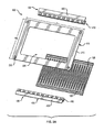
Fig. 2A is an exploded view of the cable grommet ofFig. 1 ; -
Fig. 2B is an alternative embodiment of the floor tile mounting flange of the cable grommet ofFig. 2A ; -
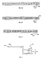
Fig. 3A is perspective view of a molded finger assembly of the cable grommet ofFig. 2A ; -
Fig. 3B is a front view of the molded finger assembly ofFig. 3A ; -
Fig. 3C is a cross-sectional view along lines "3C-3C" ofFig. 3B ; -
Fig. 3D is a side or edge view of the molded finger assembly ofFig. 3A ; -
Fig. 3E is a greatly enlarged front view of one molded finger of the molded finger assembly ofFig. 3A ; -
Fig. 3F is a front view of the molded finger assembly ofFig. 3A ; -
Fig. 3G is a cross-sectional view along lines "3G-3G" ofFig. 3F ; -
Fig. 3H is a cross-sectional view along lines "3H-3H" ofFig. 3F ; -
Fig. 3I is a cross-sectional view along lines "3I-3I" ofFig. 3F ; -
Fig. 4 is a side view of the molded finger mounting flange of the cable grommet ofFig. 2A ; -
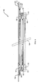
Fig. 5 is a cross-sectional view of a second preferred embodiment of a cable grommet for use with a raised floor, constructed in accordance with the invention; -
Fig. 6 is a bottom perspective view of the cable grommet ofFig. 5 ; -
Fig. 7 is a top perspective view of a typical prior art raised floor tile; -
Fig: 8 is a top perspective view of the prior art raised floor tile ofFig. 7 with the cable grommet ofFig. 1 installed therein; -
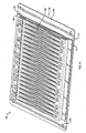
Fig. 9 is an exploded view of a third preferred embodiment of a cable grommet for use with a raised floor, constructed in accordance with the invention; -
Fig. 10 is a bottom view of the cable grommet ofFig. 9 ; -
Fig. 11 is an alternative embodiment of the floor tile mounting flange ofFig. 9 ; -
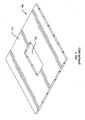
Fig 12 is a cross-sectional view of a fourth preferred embodiment of a cable grommet for use with a raised floor, constructed in accordance with the invention; -
Fig. 13 illustrates the use of a retaining member with the finger panel of the cable grommet ofFig. 9 ; -
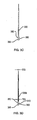
Fig. 14A is a perspective view of a finger panel support of the cable grommet ofFig. 12 ; and -
Fig. 14B is a top view of the finger panel support ofFig. 14A . - With reference to
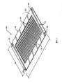
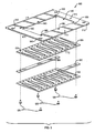
Figs. 1 and2A , in a preferred embodiment,cable grommet 100 comprises a floortile mounting flange 110, at least one pair of opposed, overlapping moldedfinger assemblies finger mounting flanges - In a preferred embodiment,
cable grommet 100 is configured to be used with a standard two-foot square raised floor tile, as described in detail below. In this configuration,cable grommet 100 has an approximate length L1 of 10.75 inches (27.3 centimeters) and an approximate width W1 of 8.25 inches (21 centimeters). The thickness or depth ofcable grommet 100 is dependent upon the number of pairs of opposed, overlapping molded finger assemblies employed in any specific configuration, as described in detail below. Note that the invention is not limited to any particular type or size of raised floor tile system. - Floor
tile mounting flange 110 defines a generallyrectangular perimeter frame 210, a generallyrectangular center opening 220, and optionally, one or more floor tileflange mounting holes 230. In a preferred embodiment, for use with a standard two-foot square raised floor tile, floortile mounting flange 110 has the same approximate length L2 and same approximate width W2 as length L1 and width W1, respectively, ofcable grommet 100, andperimeter frame 210 has an approximate thickness T2 of 0.60 inches (1.5 centimeters).Perimeter frame 210 is preferably made of a hard plastic material, such as acrylonitrile-butadiene-styrene (ABS), polyvinyl chloride (PVC), PVC-SBS blends, or metals.Perimeter frame 210 may optionally be treated to be anti-static or flame-retardant. - With reference to
Fig. 2B , in an alternative embodiment for use in a retrofit application where the floor tile is not removable or where under-floor access is limited, floortile mounting flange 180 may be constructed in two approximatelysymmetrical halves - With reference to
Figs. 3A through 3I , and in a preferred embodiment, each molded finger assembly, such as moldedfinger assembly 120, comprises a plurality of molded fingers or tangs, such as molded finger ortang 320, and asupport rib 310. - In a preferred embodiment, each molded
finger 320 is generally shaped as an isosceles triangle when viewed from the front, having a base 340, two approximatelyequal sides tip 370. Preferably, each moldedfinger 320 has an approximate height of H3 from the base 340 to thetip 370 of 5.5 inches (14 centimeters), a base 340 width W3 of approximately 0.5 inches (1.3 centimeters), an approximate thickness TB3 at thebase 340 of 0.125 inches (0.32 centimeters) tapering to an approximate thickness TT3 of 0.0625 inches (0.16 centimeters) at thetip 370. - When viewed from the front, as in
Fig. 3E , each moldedfinger 320 is preferably shaped as an isosceles triangle having twoequal sides inner core section 330 that is also preferably shaped as an isosceles triangle having twoequal sides finger 320 further definesouter wing sections sides inner core section 330. - The
inner core section 330 is preferably formed from a rigid polymer, such as Santoprene™ with a Durometer rigidity or hardness value of approximately 80A, while theouter wing sections inner core section 330 and theouter wing sections outer wing sections tile mounting flange 110, while theinner core section 330 remains generally rigid and lies generally in a plane that is essentially parallel to the plane of the floor, as described below. -
Figs. 3G, 3H and 3I provide three cross-sectional views of moldedfinger assembly 120 ofFig. 3F . As shown inFig. 3I ,inner core section 330 of moldedfinger 320 has a larger cross-sectional area thanouter wing sections base 340. The cross-sectional area ofinner core section 330 decreases near the center of the molded finger 320 (Fig. 3H ), and the cross-sectional area ofinner core section 330 is smallest at a location closest to tip 370 of molded finger 320 (Fig. 3G ). Conversely, as shown inFig. 3G ,outer wing sections triangular core section 330 at a location closest to tip 370 of moldedfinger 320. The cross-sectional areas ofouter wing sections Fig. 3H ), and the cross-sectional areas ofouter wing sections Fig. 3I ). - The molded
fingers 320 are securely mounted at theirbase 340 toelongated support rib 310, such that the moldedfingers 320 extend generally perpendicular to supportrib 310. As shown inFig. 3B , the moldedfingers 320 are preferably closely-packed, such that thebase 340 of one moldedfinger 326 is proximate to and slightly spaced from thebase 340 of the next moldedfinger 327. In alternate embodiments, thebase 340 of one moldedfinger 326 may be adjacent to thebase 340 of the next moldedfinger 327. - When viewed from the side, as shown in
Fig. 3D ,support rib 310 defines a generally rectangular or semi-circular-shapedtop portion 350 and a generally rectangular or semi-circular-shapedbottom portion 355.Top portion 350 andbottom portion 355 are connected by anelongated center section 360. The "dumbbell" shape of thesupport rib 310 is configured to mount securely within supportrib mounting channel 410 of moldedfinger mounting flanges Support rib 310 is preferably made from the same rigid polymer as theinner core section 330. In alternate embodiments,support rib 310 is made from a polymer that is more rigid thaninner core section 330. The moldedfingers 320 and thesupport rib 310 may optionally be treated to be anti-static or flame-retardant. - As shown in
Figs. 2A and4 , in a preferred embodiment, moldedfinger mounting flanges frame mounting section 420 and a generally rectangular, elongated supportrib mounting channel 410. Perimeterframe mounting section 420 is sized and shaped to mount the moldedfinger mounting flange 130 to the underside of theperimeter frame 210 of floortile mounting flange 110. - As shown in
Fig. 4 , supportrib mounting channel 410 is generally "U"-shaped when viewed in cross section, and comprises one ormore tabs 415 on each of theinterior walls 412 of supportrib mounting channel 410.Tabs 415 are configured to accept and securely hold theelongated center section 360 ofsupport rib 310 of one molded finger assembly, such as moldedfinger assembly 125. - In a preferred embodiment,
cable grommet 100 is assembled by sliding thesupport rib 310 of one moldedfinger assembly 120 into the supportrib mounting channel 410 of one moldedfinger mounting flange 130, and coupling thetop surface 430 of perimeterframe mounting section 420 to the underside of theperimeter frame 210, as shown inFigs. 5 and6 . Moldedfinger mounting flange 135 is similarly assembled and coupled to theperimeter frame 210. - When assembled, the
tips 370 of the moldedfingers 320 in the first moldedfinger assembly 120 extend across at least the majority of the center opening 220 of floortile mounting flange 110, toward thebases 340 of the moldedfingers 320 in the second moldedfinger assembly 125. Similarly, thetips 370 of the moldedfingers 320 in the second moldedfinger assembly 125 extend across at least the majority of the center opening 220 of the floortile mounting flange 110, toward thebases 340 of the moldedfingers 320 in the first moldedfinger assembly 120. This configuration of opposing, overlapping molded fingers provides an efficient air barrier that restricts the escape of cooling air from the under-floor ducts or plenums. - The cable grommet of the invention may be configured with more than one pair of opposed, overlapping molded finger assemblies. For example,
cable grommet 140 ofFigs. 5 and6 is configured with two pairs of opposed, overlapping molded finger assemblies: top moldedfinger assemblies finger assemblies Cable grommet 140 further comprises two pairs of molded finger mounting flanges: top moldedfinger mounting flanges finger mounting flanges finger mounting flanges finger mounting flanges finger assemblies finger mounting flanges Fig. 5 . The thickness of the cable grommet is determined by the number of molded finger assemblies used in the configuration. - As previously stated,
cable grommet 100 is configured to be mounted within a prior art standard two-foot square raised floor tile, such asfloor tile 700 ofFig. 7 .Floor tile 700 is generally rectangular and defines a generally flattop surface 710 and a generallyrectangular opening 720. Note that invention is not limited to any particular size or shape prior art floor tile. -
Fig. 8 shows acable grommet 100 of the invention mounted within priorart floor tile 700. In a preferred embodiment,cable grommet 100 is sized and shaped such that at least a portion ofperimeter frame 210 of floortile mounting flange 110 rests along thetop surface 710 offloor tile 700.Cable grommet 100 may be secured tofloor tile 700 with screws at floor tileflange mounting holes 230, although other known methods for securing the cable grommet to the floor tile may be used. When in use, and as shown inFig. 5 , power and data cables, such as cable 730 (shown in dotted lines), may be routed under the raised floor and passed through the one or more pairs of opposed, overlapping molded finger assemblies. Thesides fingers 320 bend around the cables while theinner core section 330 remains generally rigid and lies generally in a plane that is essentially parallel to the plane of the floor, to restrict the escape of cooling air from under the floor. - An additional preferred embodiment of a
cable grommet 800 is shown inFigs. 9 and10 .Cable grommet 800 comprises a floortile mounting flange 810, two die-cut finger panels finger panel spacers 830. Another preferred embodiment of acable grommet 1000 is shown inFig. 12 .Cable grommet 1000 comprises threefinger panels finger panel spacers - In a preferred embodiment,
cable grommet 800 is configured to be used with a standard two-foot square raised floor tile, as described below, with an approximate length L10 of 10.75 inches (27.3 centimeters) and an approximate width W10 of 8.25 inches (21 centimeters). The thickness ofcable grommet 800 is dependent upon the number of finger panels, finger panel spacers, and finger panel supports employed in any specific configuration, as described in detail below. Note that the invention is not limited to any particular type or size of raised floor tile system. - Floor
tile mounting flange 810 defines a generallyrectangular perimeter frame 910, a generallyrectangular opening 920, one or more fingerpanel mounting holes 930, and optionally, one or more floortile mounting holes 940. In a preferred embodiment, for use with a standard two-foot square raised floor tile, floortile mounting flange 810 has the same approximate length L11 and same approximate width W11, respectively, ofcable grommet 800, andperimeter frame 910 has an approximate thickness T11 of 0.60 inches (1.5 centimeters).Perimeter frame 910 is preferably made of a hard plastic material, such as acrylonitrile-butadiene-styrene (ABS), polyvinyl chloride (PVC), PVC-SBS blends, or metals.Perimeter frame 210 may optionally be treated to be anti-static or flame-retardant. - With reference to
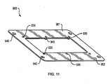
Fig. 11 , in an alternative embodiment for use in a retrofit application where the floor tile is not removable or where under-floor access is limited, floortile mounting flange 980 may be constructed in two approximatelysymmetrical halves - In a preferred embodiment, each finger panel, such as
finger panel 822, is generally rectangular with an approximate length L12 of 9.25 inches (23.5 centimeters), an approximate width W12 of 7.25 inches (18.4 centimeters), and an approximate thickness T12 of 0.60 inches (1.5 centimeters), and is made from a rigid polymer such as Santoprene™ with a Durometer rigidity or hardness value of approximately 80A. The finger panels may optionally be treated to be anti-static or flame retardant. The finger panels are preferably mounted to theperimeter frame 910 of floortile mounting flange 810, and optionally, to thefinger panel spacers 830, with a plurality of fingerpanel mounting studs 945 and an equal number of fingerpanel mounting screws 935 inserted through fingerpanel mounting holes 930, although other known methods may be used. - In a preferred embodiment,
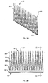
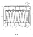
finger panel 822 defines a generallysinusoidal cut 950 along its length that extends through the thickness of thefinger panel 822. Thesinusoidal cut 950 extends across at least the majority of the width of thefinger panel 822, such that thepeaks 951 of thesinusoidal cut 950 are proximate to, but not in contact with, the fingerpanel mounting holes 930.Finger panel 822 further defines a plurality ofshort cuts 960 that intersect with and run generally perpendicular to,sinusoidal cut 950.Short cuts 960 are spaced approximately 0.25 inches (0.60 centimeters) apart from each other along the width offinger panel 822. Theshort cuts 960 similarly extend through the thickness of thefinger panel 822. The combination of thesinusoidal cut 950 and theshort cuts 960 create openings for the passage of cables through thefinger panel 822. - The cable grommet of the invention may be configured with one, two or more finger panels. For example,
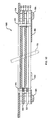
cable grommet 1000 ofFig. 12 is shown with optionalthird finger panel 823, shown in dotted lines, and optional second pair offinger panel spacers 831. Additional finger panels and finger panel spacers may be configured in the same manner, as required for a specific installation. - As shown in
Figs. 12 ,14A and 14B , an optional pair of elongated finger panel supports 990 may be used to support the weight of the finger panels and to help prevent the fingers formed by the edges of thecuts finger panel support 990 defines a first essentiallystraight edge 991, an opposingedge 992 that defines a generally sinusoidal shape, and two or more finger panelspacer mounting holes 993. Finger panel supports 990 are preferably coupled to the finger panels by inserting the fingerpanel mounting screws 935 through the finger panelspacer mounting holes 993, although other known methods may be used. - In a preferred embodiment, the length L14 of
finger panel support 990 is approximately the same as the length L12 of afinger panel 822, and the width W14 offinger panel support 990 is approximately one quarter of the width W12 of afinger panel 822.Finger panel support 990 if preferably made of a flexible yet rigid material, such as polycarbonate resin thermoplastic, for example, Lexan®. - The thickness of the cable grommet is determined by the number of finger panels, finger panel spacers, and finger panel supports used in a particular configuration.
- As shown in
Fig. 12 , power and data cables may be routed under the raised floor and passed through the openings in thefinger panels 821 and 822 (and optional finger panel 823) formed by thesinusoidal cut 950 and theshort cuts 960. When a cable 730 (shown in dotted lines) is inserted through one of these openings the edges of the cuts form a plurality of fingers that bend around the cable, while the surrounding surface of the finger panel remains generally rigid and lies generally in a plane that is essentially parallel to the plane of the floor, restricting the escape of cooling air from under the floor. - As shown in
Figs. 12 and13 , retainingmembers 970 may be inserted through one or more of the fingerpanel mounting holes 930 to further secure the finger panels, particularly at its edges. In a preferred embodiment, retainingmember 970 comprises aconical tip 971, a circular base with an essentiallyflat bottom 972, and a generallycylindrical center section 973.Center section 973 defines a plurality of ridges that are configured to hold the retainingmember 970 in place. - When used, the finger panel spacers 830 increase the insulation gap between each pair of finger panels and improve the flexibility of the fingers. As shown in
Fig. 9 , the finger panel spacers 830 are coupled to thefinger panels - As with
cable grommet 100,cable grommet 800 is sized and shaped such that at least a portion ofperimeter frame 910 rests along thetop surface 710 ofart floor tile 700, shown inFig. 7 .Cable grommet 800 may be secured tofloor tile 700 with screws at floortile mounting holes 940, although other known methods for securing the cable grommet to the floor tile may be used.
Claims (14)
- A floor grommet (100; 140), comprising:a mounting flange (110) comprising a perimeter frame (210), where the perimeter frame (210) defines an opening (220);first and second finger assemblies (120, 125; 121,126), the first finger assembly (120; 121) opposing the second finger assembly (125; 126), where each finger assembly (120, 125; 121,126) comprises a plurality of fingers (320), and each finger (320) comprises a base portion (340) and a tip portion (370);first and second finger mounting flanges (130, 135; 131,136);where the first finger mounting flange (130; 131) is coupled to the first finger assembly (120; 121) and further coupled to a first side of the perimeter frame (210); andwhere the second finger mounting flange (135; 136) is coupled to the second finger assembly (125; 126) and further coupled to an opposing second side of the perimeter frame (210);each finger (320) of the first finger assembly (120; 121) being disposed adjacent to a corresponding finger (320) of the second finger assembly (125; 126), where fingers (320) in the first finger assembly (125; 126) extend across at least the majority of the opening (220) toward the base portions (340) of the fingers (320) in the second finger assembly (125; 126), and fingers in the second finger assembly (125; 126) extend across at least the majority of the opening (220) toward the base portions (340) of the fingers (320) in the first finger assembly (120; 121);characterized in that:each of the plurality of the fingers (370) defines an inner section (330) and a pair of outer sections (335a, 335b), where the outer sections (335a, 335b) together surround at least a part of the inner section (330); andwhere the inner section (330) is configured with a first material rigidity and each of the outer sections (335a, 335b) is configured with a second material rigidity, the second material rigidity of each of the outer sections (335a, 335b) being less than the first material rigidity of the inner section (330).
- The floor grommet (100; 140) of claim 1, where a plurality of the fingers (320) define a generally triangular shape when viewed from the front.
- The floor grommet (100; 140) of claim 1, where the cross-sectional area of the inner section (330) is smallest proximate the tip portion (370) and largest proximate the base portion (340).
- The floor grommet (100; 140) of claim 1, where the cross-sectional area of the outer section (335a, 335b) is largest proximate the tip portion (370) and smallest proximate the base portion (340).
- The floor grommet (100; 140) of claim 1, where the fingers (320) in each of the finger assemblies (120, 125; 121, 126) are coupled at their base portions (340) to an elongated support rib (310).
- The floor grommet (100; 140) of claim 5, where each of the first finger mounting flange (130; 131) and the second finger mounting flange (135; 136) define an elongated mounting channel (410) sized and shaped to accommodate the elongated support rib (310).
- The floor grommet (100; 140) of claim 1, where the first material rigidity of the inner section (330) comprises an inner hardness value and the second material rigidity of each of the outer sections (335a, 335b) comprises an outer hardness value, the inner hardness value of the inner section (330) is greater than the outer hardness value of each of the outer sections (335a, 335b).
- The floor grommet (140) of claim 1, further comprising:third and fourth finger assemblies (122, 127);third and fourth finger mounting flanges (132, 137);where the third finger mounting flange (132) is coupled to the third finger assembly (122) and further coupled to the first finger mounting flange (131); andwhere the fourth finger mounting flange (137) is coupled to the fourth finger assembly (127) and further coupled to the second finger mounting flange (126);where the fingers (320) in the third finger assembly (122) extend across at least the majority of the opening (220) toward the base portions (340) of the fingers (320) in the fourth finger assembly (127), and the fingers (320) in the fourth finger assembly (127) extend across at least the majority of the opening (220) toward the base portions (340) of the fingers (320) in the third finger assembly (127).
- A floor grommet (800; 1000), comprising: a mounting flange (810) defining a perimeter frame (910) and an opening (920); and a finger panel (821, 822, 823) coupled to the mounting flange (810), the finger panel (821, 822, 823) extending across at least a majority of the opening (920); and characterized in that:the finger panel (821, 822, 823) defines a generally sinusoidal cut (950) along its length, and where the sinusoidal cut (950) extends through the thickness of the finger panel (821, 822, 823);where the finger panel (821, 822, 823) further defines a plurality of short cuts (960) that intersect with and run generally perpendicular to the sinusoidal cut (950), and at least a majority of the short cuts (960) extend through the thickness of the finger panel (821, 822, 823)where the sinusoidal cut (950) extends across at least the majority of the width of the finger panel (821, 822, 823).
- The floor grommet (800; 1000) of claim 9, further comprising a second finger panel (821, 822, 823) and a pair of finger panel spacers (830), where the first finger panel (821, 822, 823) is coupled to a first side of each of the finger panel spacers (830) and the second finger panel (821, 822, 823) is coupled to an opposing second side of each finger panel spacer (830).
- An assembly for use in a floor grommet (100; 140), comprising:an elongated support rib (310);a plurality of fingers (320), where at least a majority of the fingers (320) each comprise a base portion (340) and a tip portion (370), and are coupled to the elongated support rib (310) at their base portions (340), such that at least the majority of the fingers (320) extend generally perpendicular to the support rib (310);where at least the majority of the fingers (320) each define an inner section (330) and a pair of outer sections (335a, 335b), where the outer sections (335a, 335b) together surround at least a part of the inner section (330); and characterized in that:the inner section (330) is configured with a first material rigidity and the outer sections (335a, 335b) are configured with a second material rigidity, the second material rigidity of the outer sections (335a, 335b) being less than the first material rigidity of the inner section (330).
- The assembly of claim 11, where the cross-sectional area of the inner section (330) is smallest proximate the tip portion (370) and largest proximate the base portion (340), and where the cross-sectional area of the outer sections (335a, 335b) is largest proximate the tip portion (370) and smallest proximate the base portion (340);
- A panel for use in a floor grommet (800; 1000), characterized by comprising:a first generally rectangular finger panel (821, 822, 823) defining a generally sinusoidal cut (950) along its length, where the sinusoidal cut (950) extends through the thickness of the finger panel (821, 822, 823), and further defining a plurality of short cuts (960) that intersect with and run generally perpendicular to the sinusoidal cut (950), where at least a majority of the short cuts (960) extend through the thickness of the finger panel (821, 822, 823); andwhere the sinusoidal cut (950) extends across at least a majority of a width of the finger panel (821, 822, 823).
- The panel of claim 13, further comprising a second generally rectangular finger panel (821, 822, 823) coupled to the first finger panel (821, 822, 823).
Applications Claiming Priority (2)
| Application Number | Priority Date | Filing Date | Title |
|---|---|---|---|
| US40879410P | 2010-11-01 | 2010-11-01 | |
| PCT/US2011/058732 WO2012061352A1 (en) | 2010-11-01 | 2011-11-01 | Cable grommet for use with a raised floor |
Publications (3)
| Publication Number | Publication Date |
|---|---|
| EP2636112A1 EP2636112A1 (en) | 2013-09-11 |
| EP2636112A4 EP2636112A4 (en) | 2014-04-23 |
| EP2636112B1 true EP2636112B1 (en) | 2016-01-06 |
Family
ID=46024799
Family Applications (1)
| Application Number | Title | Priority Date | Filing Date |
|---|---|---|---|
| EP11838658.0A Not-in-force EP2636112B1 (en) | 2010-11-01 | 2011-11-01 | Cable grommet for use with a raised floor |
Country Status (4)
| Country | Link |
|---|---|
| US (1) | US8716602B2 (en) |
| EP (1) | EP2636112B1 (en) |
| CN (1) | CN103262372A (en) |
| WO (1) | WO2012061352A1 (en) |
Families Citing this family (13)
| Publication number | Priority date | Publication date | Assignee | Title |
|---|---|---|---|---|
| EP2429272A2 (en) | 2010-09-10 | 2012-03-14 | Chatsworth Products, Inc. | Cable pass-through panel for electronic equipment enclosure |
| US8683762B2 (en) * | 2012-04-04 | 2014-04-01 | International Business Machines Corporation | Data center flooring arrangements |
| US10211630B1 (en) * | 2012-09-27 | 2019-02-19 | Google Llc | Data center with large medium voltage domain |
| CN103796485A (en) * | 2012-11-01 | 2014-05-14 | 鸿富锦精密工业(深圳)有限公司 | Electronic device |
| JP6566214B2 (en) * | 2014-05-28 | 2019-08-28 | 国立大学法人 岡山大学 | Restricted growth type adenovirus expressing the REIC gene |
| USD889936S1 (en) * | 2019-01-27 | 2020-07-14 | Thomas DeCosta | Brush plate assembly |
| US11510331B2 (en) * | 2020-09-10 | 2022-11-22 | Dell Products, L.P. | Profile-modeling cable clip for sealing airflow in an information handling system (IHS) chassis |
| US11678456B1 (en) | 2020-12-15 | 2023-06-13 | Chatsworth Products, Inc. | Slidable mounting hardware for electronic equipment enclosure and method for installing same |
| US11622458B1 (en) * | 2020-12-15 | 2023-04-04 | Chatsworth Products, Inc. | Brush port assembly and method for installing same |
| US11818860B1 (en) | 2020-12-15 | 2023-11-14 | Chatsworth Products, Inc. | Frame structure for electronic equipment enclosure |
| US12048108B1 (en) | 2020-12-15 | 2024-07-23 | Chatsworth Products, Inc. | Caster attachment system using mating features |
| US11920392B1 (en) | 2021-02-02 | 2024-03-05 | Chatsworth Products, Inc. | Electrical bonding door hinges |
| USD1103747S1 (en) * | 2023-10-16 | 2025-12-02 | Baxter International Inc. | Cable retainer |
Family Cites Families (10)
| Publication number | Priority date | Publication date | Assignee | Title |
|---|---|---|---|---|
| NL8701274A (en) | 1987-05-29 | 1988-12-16 | Pidou Bv | TRANSIT DEVICE. |
| DE3832229C1 (en) | 1988-09-22 | 1990-01-18 | Daimler-Benz Aktiengesellschaft, 7000 Stuttgart, De | Line lead-through for a housing wall |
| US5101079A (en) * | 1990-07-11 | 1992-03-31 | Thomas & Betts Corporation | Enclosure for an electrical terminal block including barrier means for a cable entry opening |
| US5994644A (en) * | 1998-02-20 | 1999-11-30 | Rindoks; Kurt P. | Modular furniture raceway component |
| US6278061B1 (en) | 1999-10-28 | 2001-08-21 | Avaya Technology Corp. | Concentric retainer mechanism for variable diameter cables |
| WO2003023922A2 (en) * | 2001-09-13 | 2003-03-20 | Triton Technology Systems, Inc. | A tooless self closing floor grommet closure for cable openings |
| US7507912B1 (en) * | 2007-10-01 | 2009-03-24 | Upsite Technologies, Inc. | Grommet for cables |
| USD597823S1 (en) | 2007-10-15 | 2009-08-11 | Upsite Technologies, Inc. | Grommet |
| USD571641S1 (en) | 2007-10-15 | 2008-06-24 | Upsite Technologies, Inc. | Grommet |
| JP5123082B2 (en) | 2008-07-03 | 2013-01-16 | アトムメディカル株式会社 | Grommet structure in incubator |
-
2011
- 2011-11-01 WO PCT/US2011/058732 patent/WO2012061352A1/en not_active Ceased
- 2011-11-01 US US13/286,360 patent/US8716602B2/en active Active
- 2011-11-01 CN CN201180052732XA patent/CN103262372A/en active Pending
- 2011-11-01 EP EP11838658.0A patent/EP2636112B1/en not_active Not-in-force
Also Published As
| Publication number | Publication date |
|---|---|
| US20120279779A1 (en) | 2012-11-08 |
| US8716602B2 (en) | 2014-05-06 |
| EP2636112A1 (en) | 2013-09-11 |
| CN103262372A (en) | 2013-08-21 |
| EP2636112A4 (en) | 2014-04-23 |
| WO2012061352A1 (en) | 2012-05-10 |
Similar Documents
| Publication | Publication Date | Title |
|---|---|---|
| EP2636112B1 (en) | Cable grommet for use with a raised floor | |
| CA2590073C (en) | Electrical box assembly | |
| US20090090073A1 (en) | Cable management system for a raised floor grid system | |
| US9413149B1 (en) | Electrical box voltage divider | |
| US20110001408A1 (en) | Network Cabinet Fitting System | |
| JP5347069B2 (en) | Sealing grommet | |
| US6605782B1 (en) | Vertical cable management rack | |
| US7285027B2 (en) | Vertical cable manager | |
| US6996943B2 (en) | Cable support bracket | |
| US9929551B2 (en) | Electrical box cable connector | |
| EP3514430B1 (en) | Self-sealing membrane sleeve assembly | |
| US7544893B2 (en) | Extruded wire duct end cap | |
| US7128303B2 (en) | Fan mounting spacer assembly | |
| US9583924B2 (en) | Resilient aperture cover | |
| US7446266B1 (en) | Reconfigurable conduit body assembly for non-metallic conduit | |
| US20230106607A1 (en) | Air Sealing Electrical Box | |
| US20100126900A1 (en) | Egc compliant wire mesh cable tray system | |
| US9213160B2 (en) | Adjustable trough-couplers | |
| CA2846833A1 (en) | Strap for positioning wires/cables | |
| CN101228677B (en) | Corner fitting for cable trough system | |
| CN221447978U (en) | Integrated horizontal ladder groove wire slot | |
| US12146611B1 (en) | Adjustable slider bar for mounting an electrical box | |
| CN210183736U (en) | Guide rail device and frequency converter cabinet | |
| JP5944348B2 (en) | Air conditioning equipment for buildings and manufacturing method of air conditioning equipment | |
| TH17831A3 (en) | junction box |
Legal Events
| Date | Code | Title | Description |
|---|---|---|---|
| PUAI | Public reference made under article 153(3) epc to a published international application that has entered the european phase |
Free format text: ORIGINAL CODE: 0009012 |
|
| 17P | Request for examination filed |
Effective date: 20130423 |
|
| AK | Designated contracting states |
Kind code of ref document: A1 Designated state(s): AL AT BE BG CH CY CZ DE DK EE ES FI FR GB GR HR HU IE IS IT LI LT LU LV MC MK MT NL NO PL PT RO RS SE SI SK SM TR |
|
| DAX | Request for extension of the european patent (deleted) | ||
| A4 | Supplementary search report drawn up and despatched |
Effective date: 20140324 |
|
| RIC1 | Information provided on ipc code assigned before grant |
Ipc: H02G 3/18 20060101AFI20140318BHEP |
|
| GRAP | Despatch of communication of intention to grant a patent |
Free format text: ORIGINAL CODE: EPIDOSNIGR1 |
|
| INTG | Intention to grant announced |
Effective date: 20150526 |
|
| GRAS | Grant fee paid |
Free format text: ORIGINAL CODE: EPIDOSNIGR3 |
|
| GRAA | (expected) grant |
Free format text: ORIGINAL CODE: 0009210 |
|
| AK | Designated contracting states |
Kind code of ref document: B1 Designated state(s): AL AT BE BG CH CY CZ DE DK EE ES FI FR GB GR HR HU IE IS IT LI LT LU LV MC MK MT NL NO PL PT RO RS SE SI SK SM TR |
|
| REG | Reference to a national code |
Ref country code: GB Ref legal event code: FG4D |
|
| REG | Reference to a national code |
Ref country code: CH Ref legal event code: EP |
|
| REG | Reference to a national code |
Ref country code: IE Ref legal event code: FG4D |
|
| REG | Reference to a national code |
Ref country code: AT Ref legal event code: REF Ref document number: 769590 Country of ref document: AT Kind code of ref document: T Effective date: 20160215 |
|
| REG | Reference to a national code |
Ref country code: DE Ref legal event code: R096 Ref document number: 602011022533 Country of ref document: DE |
|
| REG | Reference to a national code |
Ref country code: LT Ref legal event code: MG4D |
|
| REG | Reference to a national code |
Ref country code: NL Ref legal event code: MP Effective date: 20160106 |
|
| REG | Reference to a national code |
Ref country code: AT Ref legal event code: MK05 Ref document number: 769590 Country of ref document: AT Kind code of ref document: T Effective date: 20160106 |
|
| PG25 | Lapsed in a contracting state [announced via postgrant information from national office to epo] |
Ref country code: NL Free format text: LAPSE BECAUSE OF FAILURE TO SUBMIT A TRANSLATION OF THE DESCRIPTION OR TO PAY THE FEE WITHIN THE PRESCRIBED TIME-LIMIT Effective date: 20160106 |
|
| PG25 | Lapsed in a contracting state [announced via postgrant information from national office to epo] |
Ref country code: FI Free format text: LAPSE BECAUSE OF FAILURE TO SUBMIT A TRANSLATION OF THE DESCRIPTION OR TO PAY THE FEE WITHIN THE PRESCRIBED TIME-LIMIT Effective date: 20160106 Ref country code: NO Free format text: LAPSE BECAUSE OF FAILURE TO SUBMIT A TRANSLATION OF THE DESCRIPTION OR TO PAY THE FEE WITHIN THE PRESCRIBED TIME-LIMIT Effective date: 20160406 Ref country code: ES Free format text: LAPSE BECAUSE OF FAILURE TO SUBMIT A TRANSLATION OF THE DESCRIPTION OR TO PAY THE FEE WITHIN THE PRESCRIBED TIME-LIMIT Effective date: 20160106 Ref country code: HR Free format text: LAPSE BECAUSE OF FAILURE TO SUBMIT A TRANSLATION OF THE DESCRIPTION OR TO PAY THE FEE WITHIN THE PRESCRIBED TIME-LIMIT Effective date: 20160106 Ref country code: IT Free format text: LAPSE BECAUSE OF FAILURE TO SUBMIT A TRANSLATION OF THE DESCRIPTION OR TO PAY THE FEE WITHIN THE PRESCRIBED TIME-LIMIT Effective date: 20160106 Ref country code: GR Free format text: LAPSE BECAUSE OF FAILURE TO SUBMIT A TRANSLATION OF THE DESCRIPTION OR TO PAY THE FEE WITHIN THE PRESCRIBED TIME-LIMIT Effective date: 20160407 |
|
| PG25 | Lapsed in a contracting state [announced via postgrant information from national office to epo] |
Ref country code: RS Free format text: LAPSE BECAUSE OF FAILURE TO SUBMIT A TRANSLATION OF THE DESCRIPTION OR TO PAY THE FEE WITHIN THE PRESCRIBED TIME-LIMIT Effective date: 20160106 Ref country code: IS Free format text: LAPSE BECAUSE OF FAILURE TO SUBMIT A TRANSLATION OF THE DESCRIPTION OR TO PAY THE FEE WITHIN THE PRESCRIBED TIME-LIMIT Effective date: 20160506 Ref country code: PT Free format text: LAPSE BECAUSE OF FAILURE TO SUBMIT A TRANSLATION OF THE DESCRIPTION OR TO PAY THE FEE WITHIN THE PRESCRIBED TIME-LIMIT Effective date: 20160506 Ref country code: AT Free format text: LAPSE BECAUSE OF FAILURE TO SUBMIT A TRANSLATION OF THE DESCRIPTION OR TO PAY THE FEE WITHIN THE PRESCRIBED TIME-LIMIT Effective date: 20160106 Ref country code: LT Free format text: LAPSE BECAUSE OF FAILURE TO SUBMIT A TRANSLATION OF THE DESCRIPTION OR TO PAY THE FEE WITHIN THE PRESCRIBED TIME-LIMIT Effective date: 20160106 Ref country code: PL Free format text: LAPSE BECAUSE OF FAILURE TO SUBMIT A TRANSLATION OF THE DESCRIPTION OR TO PAY THE FEE WITHIN THE PRESCRIBED TIME-LIMIT Effective date: 20160106 Ref country code: SE Free format text: LAPSE BECAUSE OF FAILURE TO SUBMIT A TRANSLATION OF THE DESCRIPTION OR TO PAY THE FEE WITHIN THE PRESCRIBED TIME-LIMIT Effective date: 20160106 Ref country code: LV Free format text: LAPSE BECAUSE OF FAILURE TO SUBMIT A TRANSLATION OF THE DESCRIPTION OR TO PAY THE FEE WITHIN THE PRESCRIBED TIME-LIMIT Effective date: 20160106 |
|
| REG | Reference to a national code |
Ref country code: DE Ref legal event code: R097 Ref document number: 602011022533 Country of ref document: DE |
|
| PG25 | Lapsed in a contracting state [announced via postgrant information from national office to epo] |
Ref country code: EE Free format text: LAPSE BECAUSE OF FAILURE TO SUBMIT A TRANSLATION OF THE DESCRIPTION OR TO PAY THE FEE WITHIN THE PRESCRIBED TIME-LIMIT Effective date: 20160106 Ref country code: DK Free format text: LAPSE BECAUSE OF FAILURE TO SUBMIT A TRANSLATION OF THE DESCRIPTION OR TO PAY THE FEE WITHIN THE PRESCRIBED TIME-LIMIT Effective date: 20160106 |
|
| PLBE | No opposition filed within time limit |
Free format text: ORIGINAL CODE: 0009261 |
|
| STAA | Information on the status of an ep patent application or granted ep patent |
Free format text: STATUS: NO OPPOSITION FILED WITHIN TIME LIMIT |
|
| PG25 | Lapsed in a contracting state [announced via postgrant information from national office to epo] |
Ref country code: SK Free format text: LAPSE BECAUSE OF FAILURE TO SUBMIT A TRANSLATION OF THE DESCRIPTION OR TO PAY THE FEE WITHIN THE PRESCRIBED TIME-LIMIT Effective date: 20160106 Ref country code: RO Free format text: LAPSE BECAUSE OF FAILURE TO SUBMIT A TRANSLATION OF THE DESCRIPTION OR TO PAY THE FEE WITHIN THE PRESCRIBED TIME-LIMIT Effective date: 20160106 Ref country code: SM Free format text: LAPSE BECAUSE OF FAILURE TO SUBMIT A TRANSLATION OF THE DESCRIPTION OR TO PAY THE FEE WITHIN THE PRESCRIBED TIME-LIMIT Effective date: 20160106 Ref country code: CZ Free format text: LAPSE BECAUSE OF FAILURE TO SUBMIT A TRANSLATION OF THE DESCRIPTION OR TO PAY THE FEE WITHIN THE PRESCRIBED TIME-LIMIT Effective date: 20160106 |
|
| 26N | No opposition filed |
Effective date: 20161007 |
|
| PG25 | Lapsed in a contracting state [announced via postgrant information from national office to epo] |
Ref country code: BE Free format text: LAPSE BECAUSE OF FAILURE TO SUBMIT A TRANSLATION OF THE DESCRIPTION OR TO PAY THE FEE WITHIN THE PRESCRIBED TIME-LIMIT Effective date: 20160106 |
|
| PG25 | Lapsed in a contracting state [announced via postgrant information from national office to epo] |
Ref country code: BG Free format text: LAPSE BECAUSE OF FAILURE TO SUBMIT A TRANSLATION OF THE DESCRIPTION OR TO PAY THE FEE WITHIN THE PRESCRIBED TIME-LIMIT Effective date: 20160406 Ref country code: SI Free format text: LAPSE BECAUSE OF FAILURE TO SUBMIT A TRANSLATION OF THE DESCRIPTION OR TO PAY THE FEE WITHIN THE PRESCRIBED TIME-LIMIT Effective date: 20160106 |
|
| REG | Reference to a national code |
Ref country code: DE Ref legal event code: R119 Ref document number: 602011022533 Country of ref document: DE |
|
| REG | Reference to a national code |
Ref country code: CH Ref legal event code: PL |
|
| GBPC | Gb: european patent ceased through non-payment of renewal fee |
Effective date: 20161101 |
|
| PG25 | Lapsed in a contracting state [announced via postgrant information from national office to epo] |
Ref country code: LI Free format text: LAPSE BECAUSE OF NON-PAYMENT OF DUE FEES Effective date: 20161130 Ref country code: CH Free format text: LAPSE BECAUSE OF NON-PAYMENT OF DUE FEES Effective date: 20161130 |
|
| REG | Reference to a national code |
Ref country code: IE Ref legal event code: MM4A |
|
| REG | Reference to a national code |
Ref country code: FR Ref legal event code: ST Effective date: 20170731 |
|
| PG25 | Lapsed in a contracting state [announced via postgrant information from national office to epo] |
Ref country code: LU Free format text: LAPSE BECAUSE OF NON-PAYMENT OF DUE FEES Effective date: 20161130 |
|
| PG25 | Lapsed in a contracting state [announced via postgrant information from national office to epo] |
Ref country code: FR Free format text: LAPSE BECAUSE OF NON-PAYMENT OF DUE FEES Effective date: 20161130 |
|
| PG25 | Lapsed in a contracting state [announced via postgrant information from national office to epo] |
Ref country code: IE Free format text: LAPSE BECAUSE OF NON-PAYMENT OF DUE FEES Effective date: 20161101 Ref country code: GB Free format text: LAPSE BECAUSE OF NON-PAYMENT OF DUE FEES Effective date: 20161101 Ref country code: DE Free format text: LAPSE BECAUSE OF NON-PAYMENT OF DUE FEES Effective date: 20170601 |
|
| PG25 | Lapsed in a contracting state [announced via postgrant information from national office to epo] |
Ref country code: CY Free format text: LAPSE BECAUSE OF FAILURE TO SUBMIT A TRANSLATION OF THE DESCRIPTION OR TO PAY THE FEE WITHIN THE PRESCRIBED TIME-LIMIT Effective date: 20160106 Ref country code: HU Free format text: LAPSE BECAUSE OF FAILURE TO SUBMIT A TRANSLATION OF THE DESCRIPTION OR TO PAY THE FEE WITHIN THE PRESCRIBED TIME-LIMIT; INVALID AB INITIO Effective date: 20111101 |
|
| PG25 | Lapsed in a contracting state [announced via postgrant information from national office to epo] |
Ref country code: MK Free format text: LAPSE BECAUSE OF FAILURE TO SUBMIT A TRANSLATION OF THE DESCRIPTION OR TO PAY THE FEE WITHIN THE PRESCRIBED TIME-LIMIT Effective date: 20160106 Ref country code: MC Free format text: LAPSE BECAUSE OF FAILURE TO SUBMIT A TRANSLATION OF THE DESCRIPTION OR TO PAY THE FEE WITHIN THE PRESCRIBED TIME-LIMIT Effective date: 20160106 |
|
| PG25 | Lapsed in a contracting state [announced via postgrant information from national office to epo] |
Ref country code: MT Free format text: LAPSE BECAUSE OF NON-PAYMENT OF DUE FEES Effective date: 20161101 |
|
| PG25 | Lapsed in a contracting state [announced via postgrant information from national office to epo] |
Ref country code: AL Free format text: LAPSE BECAUSE OF FAILURE TO SUBMIT A TRANSLATION OF THE DESCRIPTION OR TO PAY THE FEE WITHIN THE PRESCRIBED TIME-LIMIT Effective date: 20160106 Ref country code: TR Free format text: LAPSE BECAUSE OF FAILURE TO SUBMIT A TRANSLATION OF THE DESCRIPTION OR TO PAY THE FEE WITHIN THE PRESCRIBED TIME-LIMIT Effective date: 20160106 |