EP2635534B1 - Reactor for recovering phosphate salts from a liquid - Google Patents
Reactor for recovering phosphate salts from a liquid Download PDFInfo
- Publication number
- EP2635534B1 EP2635534B1 EP11779163.2A EP11779163A EP2635534B1 EP 2635534 B1 EP2635534 B1 EP 2635534B1 EP 11779163 A EP11779163 A EP 11779163A EP 2635534 B1 EP2635534 B1 EP 2635534B1
- Authority
- EP
- European Patent Office
- Prior art keywords
- reactor
- housing
- magnesium
- liquid
- phosphate
- Prior art date
- Legal status (The legal status is an assumption and is not a legal conclusion. Google has not performed a legal analysis and makes no representation as to the accuracy of the status listed.)
- Active
Links
- 239000007788 liquid Substances 0.000 title claims description 23
- 125000002467 phosphate group Chemical class [H]OP(=O)(O[H])O[*] 0.000 title claims 3
- 239000011777 magnesium Substances 0.000 claims description 20
- FYYHWMGAXLPEAU-UHFFFAOYSA-N Magnesium Chemical compound [Mg] FYYHWMGAXLPEAU-UHFFFAOYSA-N 0.000 claims description 16
- 229910052749 magnesium Inorganic materials 0.000 claims description 16
- 239000013078 crystal Substances 0.000 claims description 9
- 239000000463 material Substances 0.000 claims description 4
- 239000004020 conductor Substances 0.000 claims description 2
- 238000011084 recovery Methods 0.000 claims description 2
- 238000002425 crystallisation Methods 0.000 claims 1
- 230000008025 crystallization Effects 0.000 claims 1
- 150000003013 phosphoric acid derivatives Chemical class 0.000 description 18
- 229910019142 PO4 Inorganic materials 0.000 description 17
- 239000010452 phosphate Substances 0.000 description 17
- NBIIXXVUZAFLBC-UHFFFAOYSA-K phosphate Chemical compound [O-]P([O-])([O-])=O NBIIXXVUZAFLBC-UHFFFAOYSA-K 0.000 description 17
- IJGRMHOSHXDMSA-UHFFFAOYSA-N Atomic nitrogen Chemical compound N#N IJGRMHOSHXDMSA-UHFFFAOYSA-N 0.000 description 16
- 238000001556 precipitation Methods 0.000 description 11
- 238000000034 method Methods 0.000 description 10
- 239000002351 wastewater Substances 0.000 description 10
- 238000006243 chemical reaction Methods 0.000 description 9
- 229910052757 nitrogen Inorganic materials 0.000 description 8
- HEMHJVSKTPXQMS-UHFFFAOYSA-M sodium hydroxide Inorganic materials [OH-].[Na+] HEMHJVSKTPXQMS-UHFFFAOYSA-M 0.000 description 7
- XLYOFNOQVPJJNP-UHFFFAOYSA-N water Substances O XLYOFNOQVPJJNP-UHFFFAOYSA-N 0.000 description 7
- JLVVSXFLKOJNIY-UHFFFAOYSA-N Magnesium ion Chemical compound [Mg+2] JLVVSXFLKOJNIY-UHFFFAOYSA-N 0.000 description 6
- 150000002500 ions Chemical class 0.000 description 6
- 229910001425 magnesium ion Inorganic materials 0.000 description 6
- 239000007787 solid Substances 0.000 description 6
- QGZKDVFQNNGYKY-UHFFFAOYSA-O Ammonium Chemical compound [NH4+] QGZKDVFQNNGYKY-UHFFFAOYSA-O 0.000 description 5
- 238000000855 fermentation Methods 0.000 description 5
- 230000004151 fermentation Effects 0.000 description 5
- 238000004519 manufacturing process Methods 0.000 description 5
- 239000002671 adjuvant Substances 0.000 description 4
- 230000015572 biosynthetic process Effects 0.000 description 4
- 238000000926 separation method Methods 0.000 description 4
- 229910052782 aluminium Inorganic materials 0.000 description 3
- XAGFODPZIPBFFR-UHFFFAOYSA-N aluminium Chemical compound [Al] XAGFODPZIPBFFR-UHFFFAOYSA-N 0.000 description 3
- VTHJTEIRLNZDEV-UHFFFAOYSA-L magnesium dihydroxide Chemical compound [OH-].[OH-].[Mg+2] VTHJTEIRLNZDEV-UHFFFAOYSA-L 0.000 description 3
- 239000000347 magnesium hydroxide Substances 0.000 description 3
- 229910001862 magnesium hydroxide Inorganic materials 0.000 description 3
- OAICVXFJPJFONN-UHFFFAOYSA-N Phosphorus Chemical compound [P] OAICVXFJPJFONN-UHFFFAOYSA-N 0.000 description 2
- ZLMJMSJWJFRBEC-UHFFFAOYSA-N Potassium Chemical compound [K] ZLMJMSJWJFRBEC-UHFFFAOYSA-N 0.000 description 2
- 238000007792 addition Methods 0.000 description 2
- 150000001875 compounds Chemical class 0.000 description 2
- 210000003608 fece Anatomy 0.000 description 2
- 239000010871 livestock manure Substances 0.000 description 2
- 239000000395 magnesium oxide Substances 0.000 description 2
- CPLXHLVBOLITMK-UHFFFAOYSA-N magnesium oxide Inorganic materials [Mg]=O CPLXHLVBOLITMK-UHFFFAOYSA-N 0.000 description 2
- 159000000003 magnesium salts Chemical class 0.000 description 2
- AXZKOIWUVFPNLO-UHFFFAOYSA-N magnesium;oxygen(2-) Chemical compound [O-2].[Mg+2] AXZKOIWUVFPNLO-UHFFFAOYSA-N 0.000 description 2
- 239000000546 pharmaceutical excipient Substances 0.000 description 2
- 239000011574 phosphorus Substances 0.000 description 2
- 229910052698 phosphorus Inorganic materials 0.000 description 2
- 239000011591 potassium Substances 0.000 description 2
- 229910052700 potassium Inorganic materials 0.000 description 2
- 239000002244 precipitate Substances 0.000 description 2
- 239000000047 product Substances 0.000 description 2
- 239000000243 solution Substances 0.000 description 2
- 239000000126 substance Substances 0.000 description 2
- 238000011144 upstream manufacturing Methods 0.000 description 2
- 229910000861 Mg alloy Inorganic materials 0.000 description 1
- 229910017958 MgNH Inorganic materials 0.000 description 1
- 230000002411 adverse Effects 0.000 description 1
- 238000005273 aeration Methods 0.000 description 1
- 239000003513 alkali Substances 0.000 description 1
- MXZRMHIULZDAKC-UHFFFAOYSA-L ammonium magnesium phosphate Chemical compound [NH4+].[Mg+2].[O-]P([O-])([O-])=O MXZRMHIULZDAKC-UHFFFAOYSA-L 0.000 description 1
- 239000012223 aqueous fraction Substances 0.000 description 1
- 239000007864 aqueous solution Substances 0.000 description 1
- 150000001722 carbon compounds Chemical class 0.000 description 1
- 150000001768 cations Chemical class 0.000 description 1
- 238000004140 cleaning Methods 0.000 description 1
- 238000010276 construction Methods 0.000 description 1
- 238000010790 dilution Methods 0.000 description 1
- 239000012895 dilution Substances 0.000 description 1
- 230000005684 electric field Effects 0.000 description 1
- 230000005611 electricity Effects 0.000 description 1
- 239000007772 electrode material Substances 0.000 description 1
- 238000005516 engineering process Methods 0.000 description 1
- 230000002349 favourable effect Effects 0.000 description 1
- 239000006260 foam Substances 0.000 description 1
- 239000003517 fume Substances 0.000 description 1
- -1 hydroxide ions Chemical class 0.000 description 1
- 150000004679 hydroxides Chemical class 0.000 description 1
- 230000001771 impaired effect Effects 0.000 description 1
- 239000004615 ingredient Substances 0.000 description 1
- 230000005764 inhibitory process Effects 0.000 description 1
- 229910052500 inorganic mineral Inorganic materials 0.000 description 1
- YQRTZUSEPDULET-UHFFFAOYSA-K magnesium;potassium;phosphate Chemical compound [Mg+2].[K+].[O-]P([O-])([O-])=O YQRTZUSEPDULET-UHFFFAOYSA-K 0.000 description 1
- 229910052751 metal Inorganic materials 0.000 description 1
- 239000002184 metal Substances 0.000 description 1
- 239000011707 mineral Substances 0.000 description 1
- 239000010815 organic waste Substances 0.000 description 1
- 230000008635 plant growth Effects 0.000 description 1
- 239000003123 plant toxin Substances 0.000 description 1
- 230000001376 precipitating effect Effects 0.000 description 1
- 238000000746 purification Methods 0.000 description 1
- 230000000717 retained effect Effects 0.000 description 1
- 150000003839 salts Chemical class 0.000 description 1
- 238000004062 sedimentation Methods 0.000 description 1
- 239000010802 sludge Substances 0.000 description 1
- 230000002269 spontaneous effect Effects 0.000 description 1
- 229910052567 struvite Inorganic materials 0.000 description 1
- 238000004065 wastewater treatment Methods 0.000 description 1
Images


Classifications
-
- C—CHEMISTRY; METALLURGY
- C02—TREATMENT OF WATER, WASTE WATER, SEWAGE, OR SLUDGE
- C02F—TREATMENT OF WATER, WASTE WATER, SEWAGE, OR SLUDGE
- C02F1/00—Treatment of water, waste water, or sewage
- C02F1/46—Treatment of water, waste water, or sewage by electrochemical methods
- C02F1/461—Treatment of water, waste water, or sewage by electrochemical methods by electrolysis
- C02F1/463—Treatment of water, waste water, or sewage by electrochemical methods by electrolysis by electrocoagulation
-
- C—CHEMISTRY; METALLURGY
- C25—ELECTROLYTIC OR ELECTROPHORETIC PROCESSES; APPARATUS THEREFOR
- C25B—ELECTROLYTIC OR ELECTROPHORETIC PROCESSES FOR THE PRODUCTION OF COMPOUNDS OR NON-METALS; APPARATUS THEREFOR
- C25B9/00—Cells or assemblies of cells; Constructional parts of cells; Assemblies of constructional parts, e.g. electrode-diaphragm assemblies; Process-related cell features
-
- C—CHEMISTRY; METALLURGY
- C02—TREATMENT OF WATER, WASTE WATER, SEWAGE, OR SLUDGE
- C02F—TREATMENT OF WATER, WASTE WATER, SEWAGE, OR SLUDGE
- C02F1/00—Treatment of water, waste water, or sewage
- C02F1/001—Processes for the treatment of water whereby the filtration technique is of importance
-
- C—CHEMISTRY; METALLURGY
- C02—TREATMENT OF WATER, WASTE WATER, SEWAGE, OR SLUDGE
- C02F—TREATMENT OF WATER, WASTE WATER, SEWAGE, OR SLUDGE
- C02F11/00—Treatment of sludge; Devices therefor
- C02F11/02—Biological treatment
- C02F11/04—Anaerobic treatment; Production of methane by such processes
-
- C—CHEMISTRY; METALLURGY
- C02—TREATMENT OF WATER, WASTE WATER, SEWAGE, OR SLUDGE
- C02F—TREATMENT OF WATER, WASTE WATER, SEWAGE, OR SLUDGE
- C02F1/00—Treatment of water, waste water, or sewage
- C02F1/46—Treatment of water, waste water, or sewage by electrochemical methods
- C02F1/461—Treatment of water, waste water, or sewage by electrochemical methods by electrolysis
- C02F1/46104—Devices therefor; Their operating or servicing
- C02F1/46109—Electrodes
- C02F2001/46133—Electrodes characterised by the material
-
- C—CHEMISTRY; METALLURGY
- C02—TREATMENT OF WATER, WASTE WATER, SEWAGE, OR SLUDGE
- C02F—TREATMENT OF WATER, WASTE WATER, SEWAGE, OR SLUDGE
- C02F1/00—Treatment of water, waste water, or sewage
- C02F1/46—Treatment of water, waste water, or sewage by electrochemical methods
- C02F1/461—Treatment of water, waste water, or sewage by electrochemical methods by electrolysis
- C02F1/46104—Devices therefor; Their operating or servicing
- C02F1/46109—Electrodes
- C02F2001/46152—Electrodes characterised by the shape or form
-
- C—CHEMISTRY; METALLURGY
- C02—TREATMENT OF WATER, WASTE WATER, SEWAGE, OR SLUDGE
- C02F—TREATMENT OF WATER, WASTE WATER, SEWAGE, OR SLUDGE
- C02F2101/00—Nature of the contaminant
- C02F2101/10—Inorganic compounds
- C02F2101/105—Phosphorus compounds
-
- C—CHEMISTRY; METALLURGY
- C02—TREATMENT OF WATER, WASTE WATER, SEWAGE, OR SLUDGE
- C02F—TREATMENT OF WATER, WASTE WATER, SEWAGE, OR SLUDGE
- C02F2201/00—Apparatus for treatment of water, waste water or sewage
- C02F2201/002—Construction details of the apparatus
- C02F2201/003—Coaxial constructions, e.g. a cartridge located coaxially within another
-
- C—CHEMISTRY; METALLURGY
- C02—TREATMENT OF WATER, WASTE WATER, SEWAGE, OR SLUDGE
- C02F—TREATMENT OF WATER, WASTE WATER, SEWAGE, OR SLUDGE
- C02F2201/00—Apparatus for treatment of water, waste water or sewage
- C02F2201/46—Apparatus for electrochemical processes
- C02F2201/461—Electrolysis apparatus
- C02F2201/46105—Details relating to the electrolytic devices
- C02F2201/4616—Power supply
- C02F2201/4617—DC only
Definitions
- the WO 00200101019735 A1 describes a reactor for removing dissolved nitrogen and phosphate from the aqueous portion of manure by electrochemical precipitation.
- the reactor described therein requires relatively high electrical voltages and is thus energy and cost intensive. It is also disadvantageous that nitrogen and phosphate, which are organically bound in the aqueous fraction of the manure, are not removed by the process described. As a result, this wastewater must be fed to a subsequent purification in a wastewater treatment plant.
- the design of the reactor is disadvantageous in that large areas are created by the arrangement of the electrodes in which the liquid to be cleaned has no direct contact with the electrodes. In addition, the geometry of the sacrificial anode liberates more magnesium than necessary. Both significantly reduce the efficiency of the reactor. Furthermore, in this method, the use of aluminum-containing electrodes, the plant poison aluminum in the precipitate. When this product is placed on the ground, the aluminum may be released and adversely affect plant growth.
- An electrochemical precipitation reactor for MAP is from the WO 2007/009749 A1 known.
- the reactor is not suitable for the precipitation of other phosphate salts.
- the construction of the reactor also leaves no automatic separation between purified wastewater and precipitated MAP, so that the reactor must be subordinated to another apparatus for solid-liquid separation.
- a much higher expenditure on equipment is required, because the design of the housing of the reactor can not be operated as a cathode.
- the magnesium is unevenly dissolved, because the spatial arrangement of the electrodes in the reactor only one side of the anode is included in the reaction.
- an anaerobic fermentation process be connected upstream of the reactor according to the invention.
- nitrogen and phosphorus which are organically bound, are broken down into inorganic, water-soluble ions.
- ammonium (NH 4 + ) and phosphate (PO 4 3- ) the phosphate salts, in particular MAP and KMP can be formed.
- NH 4 + ammonium
- phosphate (PO 4 3- ) the phosphate salts, in particular MAP and KMP can be formed.
- nitrogen and phosphate which are bound to or in organic substance or cell mass, converted into a water-soluble form and are thus the production of plant excipients available.
- biogas which has considerable market value as an energy supplier, is created during this process.
- the sacrificial anode consists essentially of magnesium.
- this also includes electrode materials that consist of a magnesium alloy or magnesium with minor additions of other ingredients.
- the reactor according to the invention has an inlet for the phosphate-containing liquid, a drain for the purified liquid and a withdrawal for the precipitated phosphate salts.
- the crystals can be removed via the trigger by means of a shut-off valve, such as a seat or disc valve or a ball valve, from the reactor without the Zu or Altered process and thus the cleaning performance of the reactor is impaired.
- An advantageous embodiment of the reactor according to the invention provides to operate the reactor as an upflow reactor.
- the inlet is at the bottom of the reactor.
- the waste water flows upwards and escapes at the top.
- This arrangement has the advantage that there is an automatic separation of liquid flowing upwards and precipitated salts sinking to the bottom.
- the reactor can also be operated as a downstream reactor, with liquid and solid moving in the same direction. This accelerates the sedimentation rate of the precipitated phosphate salts. This means that the reactor can be built smaller at the same throughput.
- the reactor according to the invention works even better if it has an inclined bottom. This will allow the precipitated crystals to slide down the slope and collect on the fume hood. This allows the crystals to be removed from the reactor without interrupting its continuous operation. Reached is the formation of the slope by a preferably conical bottom. However, the shape of a pyramid is also conceivable.
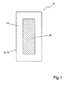
- FIG. 1 shows a schematic representation of a reactor 10 according to the invention.
- the reactor 10 has a housing 12.
- the housing 12 serves to receive a phosphate-containing liquid 14.
- an electrode 16 is arranged in the center of the housing 12.
- the electrode 16 is a so-called sacrificial anode, which is connected to the positive pole of a DC power source, not shown in the drawing is while the housing 12 forms the cathode 18, which is connected to a negative terminal of the DC power source.
- the sacrificial anode 16 is made of a magnesium-containing material so that magnesium ions enter the liquid 14 as soon as an electrical voltage is applied to the electrodes 16 and 18.
- the phosphate salts formed are sparingly soluble in aqueous solution and precipitate as crystals settling at a bottom of the reactor 10.
- An embodiment of the reactor 10 according to the invention provides a galvanic operation.
- the two electrodes 16, 18 are not connected to the external DC power source.
- the magnesium ions are converted into solution by galvanic operation.
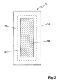
- FIG. 2 shows a first embodiment variant of the reactor according to the invention 10. Shown is the housing 12 of the reactor and centered therein arranged as a sacrificial anode electrode 16. Concentrically between the housing 12 and electrode 16 is arranged the cathode 18. In this particular arrangement, the distance between the sacrificial anode 16th and inert cathode 18 are kept minimal so that the ions involved in the precipitation immediately contact each other.
- FIG. 3 the reactor 10 is shown.
- An outlet 26 is located at the top at the side of the housing 12 of the reactor 10.
- An optional return 28 connects the outlet 26 to the inlet 24.
- Below the preferably conical bottom 22 is the trigger 30th
- the phosphate-containing liquid 14 flows through the inlet 24 from bottom to top through the reactor 10 and leaves it through the drain 26.
- the precipitated phosphate salts slide on the inclined plane of the conical bottom 22 down and are removed via the trigger 30. In this way, the reactor 10 can be operated continuously and the precipitated and settled crystals can be removed at any time without changing a flow rate of the reactor.
- About the optional return 28 already purified liquid 14 is recycled as circulating water to the reactor 10.
- FIG. 4 shows a third embodiment of the invention of the reactor 10.
- the reactor 10 is flowed downward.
- the inlet 24 is located at the top on the side of the housing 12.
- the outlet 26 is located laterally on the cone-shaped bottom 22.
- the optional return 28 connects the outlet 26 with the inlet 24.
- Below the conical bottom 22 of the trigger 30 is arranged.
- the phosphate-containing liquid 14 flows through the inlet 24 from top to bottom through the reactor 10 and leaves it through the outlet 26. Precipitated phosphate salts are withdrawn via the flue 30, without affecting the operation of the reactor. Via the return 28, already purified liquid 14 is returned to the reactor 10 as circulating water.
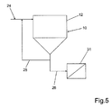
- FIG. 5 shows a further embodiment of the reactor 10.
- the reactor 10 is flowed downward.
- the inlet 24 is located at the top on the side of the housing 12.
- the outlet 26 is located at the bottom of the conical bottom 22 and leads from there to a downstream filter 31.
- the optional return 28 connects the outlet 26 to the inlet 24.
- the precipitated phosphate salts are discharged from the reactor 10 together with the purified liquid 14.
- the phosphate salts are separated from the liquid 14. It is possible, via the return 28, the reactor 10 to supply seed crystals.
- FIG. 6 an application of the inventive reactor 10 in the production of biogas from phosphorus-containing wastewater is shown schematically.
- a wastewater stream 32 of organic origin is fed to a bioreactor 34.
- Anaerobic fermentation processes convert the organic carbon compounds contained in the solids into biogas and mineral residues. This results in ammonium and phosphate-containing process water 36.
- any solids 40 contained in a filter 38 are separated.
- the retained in the filter 38 solids 40 are fed back to the bioreactor 34.
- the phosphate salts are separated in the manner described above.
- the ammonium and phosphate-free effluent 26 may be partially recycled to the bioreactor 34. This prevents inhibition of the fermentation process caused by a high ammonium concentration.
Description
Die Erfindung betrifft einen Reaktor zur vollständigen Abtrennung von Phosphat aus einer Flüssigkeit und Rückgewinnung von Phosphatsalzen mit einem Gehäuse und zwei Elektroden unterschiedlicher Polarität.The invention relates to a reactor for the complete separation of phosphate from a liquid and recovery of phosphate salts with a housing and two electrodes of different polarity.
Phosphatsalze wie Magnesiumammoniumphosphat(im Folgenden als MAP abgekürzt) oder Kaliummagnesiumphosphat (im Folgenden als KMP abgekürzt) sind hochwertige Pflanzenhilfsstoffe für die eine hohe Nachfrage besteht. Die Elemente Stickstoff, Kalium, Magnesium und Phosphat, aus denen diese Pflanzenhilfsstoffe aufgebaut sind, sind typischerweise in allen festen oder flüssigen organischen Abfällen enthalten. Während Kalium, Magnesium und weitere Ionen in Form wasserlöslicher Kationen vorliegen, sind Stickstoff und Phosphat zum überwiegenden Teil an oder in organischer Substanz bzw. Zellmasse gebunden. Damit steht ein Großteil von Stickstoff und Phosphat zur Produktion von Pflanzenhilfsstoffen nicht zur Verfügung. Deshalb ist es notwendig, Stickstoff und Phosphat in ihre, für die Fällung geeignete, anorganische Form umzuwandeln.Phosphate salts such as magnesium ammonium phosphate (hereinafter abbreviated as MAP) or potassium magnesium phosphate (hereinafter abbreviated to KMP) are high-quality plant adjuvants for which there is a high demand. The elements nitrogen, potassium, magnesium and phosphate which make up these plant adjuvants are typically present in all solid or liquid organic wastes. While potassium, magnesium and other ions are present in the form of water-soluble cations, nitrogen and phosphate are predominantly bound to or in organic substance or cell mass. Thus, a large part of nitrogen and phosphate for the production of plant excipients is not available. Therefore, it is necessary to convert nitrogen and phosphate into their inorganic form suitable for precipitation.
Die spontane Ausfällung von MAP oder KMP ist limitiert durch die üblicherweise sehr niedrige Magnesium-Konzentration im Abwasser. Bekannt ist die Zugabe von Magnesiumhydroxid, Magnesiumoxid oder löslichen Magnesiumsalzen zur MAP-Fällung. Der Nachteil dabei ist die schlechte Löslichkeit der Oxide, sowie der salzähnlichen Hydroxide. Bei Zugabe von Magnesiumhydroxid oder Magnesiumoxid zum Abwasser, lösen sich diese Verbindungen nur sehr langsam und zu einem geringen Anteil. Das führt dazu, dass kontinuierlich gerührt oder umgewälzt werden muss, was aber einen Mehraufwand an Technik und Energie und damit auch an Kosten verursacht. Darüber hinaus müssen beide Verbindungen aufgrund ihrer schlechten Löslichkeit überstöchiometrisch dosiert werden, da andernfalls eine unvollständige Fällung der gewünschten Pflanzenhilfsstoffe eintritt und erhebliche Mengen Phosphat im Abwasser verbleiben. Werden Magnesiumsalze vorab in eine Lösung überführt, verschlechtert sich durch die Verdünnung mit Wasser der Wirkungsgrad des Verfahrens.The spontaneous precipitation of MAP or KMP is limited by the usually very low magnesium concentration in the wastewater. The addition of magnesium hydroxide, magnesium oxide or soluble magnesium salts to MAP precipitation is known. The disadvantage here is the poor solubility of the oxides, as well as the salt-like hydroxides. When magnesium hydroxide or magnesium oxide is added to the wastewater, these compounds dissolve only very slowly and to a small extent. As a result, it must be continuously stirred or circulated, which, however, causes additional expenditure on technology and energy and thus costs. In addition, both compounds must be metered in excess of stoichiometry due to their poor solubility, otherwise incomplete precipitation of the desired plant adjuvants occurs and significant amounts of phosphate remain in the wastewater. If magnesium salts are converted into a solution in advance, the dilution with water worsens the efficiency of the procedure.
Der optimale pH-Wert zur Fällung von MAP liegt bei 9. Abwasser hat normalerweise pH-Werte zwischen 5 und 7. Deswegen wird zu Anhebung des pH-Wertes eine Lauge zugegeben. Bei Verwendung einer löslichen Lauge, wie beispielsweise Natriumhydroxid. Bei Verwendung einer schlechtlöslichen Lauge wie z.B. Magnesiumhydroxid, löst sich dieses kaum in Wasser, und die vorangehend erwähnten Nachteile treten ein.The optimum pH for precipitating MAP is 9. Waste water normally has pH values between 5 and 7. Therefore, a lye is added to raise the pH. When using a soluble lye, such as sodium hydroxide. When using a poorly soluble alkali, e.g. Magnesium hydroxide, this dissolves hardly in water, and the above-mentioned disadvantages occur.
Eine weitere Möglichkeit zur Einstellung eines für die Fällung günstigen pH-Wertes ist in der
Die
Der darin beschriebene Reaktor benötigt relativ hohe elektrische Spannungen und ist damit energie- und kostenintensiv. Nachteilig ist auch, dass Stickstoff und Phosphat, die organisch gebunden im wässrigen Anteil der Gülle vorliegen durch das beschriebene Verfahren nicht entfernt werden. In Folge dessen muss dieses Abwasser einer anschließenden Reinigung in einer Kläranlage zugeführt werden. Nachteilig ist die Konstruktion des Reaktors insofern, dass durch die Anordnung der Elektroden große Bereiche entstehen in denen die zu reinigende Flüssigkeit keinen direkten Kontakt mit den Elektroden hat. Zudem wird durch die Geometrie der Opferanode mehr Magnesium als nötig freigesetzt. Beides reduziert die Effizienz des Reaktors erheblich. Weiterhin gelangt bei diesem Verfahren durch den Einsatz von aluminiumhaltigen Elektroden das Pflanzengift Aluminium in das Fällungsprodukt. Wird dieses Produkt auf den Boden gegeben, kann das Aluminium freigesetzt werden und das Pflanzenwachstum nachteilig beeinflussen.The reactor described therein requires relatively high electrical voltages and is thus energy and cost intensive. It is also disadvantageous that nitrogen and phosphate, which are organically bound in the aqueous fraction of the manure, are not removed by the process described. As a result, this wastewater must be fed to a subsequent purification in a wastewater treatment plant. The design of the reactor is disadvantageous in that large areas are created by the arrangement of the electrodes in which the liquid to be cleaned has no direct contact with the electrodes. In addition, the geometry of the sacrificial anode liberates more magnesium than necessary. Both significantly reduce the efficiency of the reactor. Furthermore, in this method, the use of aluminum-containing electrodes, the plant poison aluminum in the precipitate. When this product is placed on the ground, the aluminum may be released and adversely affect plant growth.
Ein elektrochemischer Fällungsreaktor für MAP ist aus der
Der Erfindung liegt die Aufgabe zugrunde, einen Reaktor bereitzustellen, mit dessen Hilfe phosphathaltige Abwässer aufbereitet und einer weiteren Verwendung zugeführt werden können. Des Weiteren liegt der Erfindung die Aufgabe zugrunde, einen Reaktor zu Gewinnung von Phosphatsalzen als Pflanzenhilfsstoffe bereitzustellen, welches die oben gennannten Nachteile des Standes der Technik überwindet.The object of the invention is to provide a reactor with the aid of which phosphate-containing effluents can be treated and fed to a further use. Furthermore, the invention has for its object to provide a reactor for the production of phosphate salts as plant adjuvants, which overcomes the above-mentioned disadvantages of the prior art.
Die Aufgabe wird erfindungsgemäß gelöst durch einen Reaktor mit einem Gehäuse. Im Zentrum des Gehäuses ist eine Opferanode aus Magnesium oder einem magnesiumhaltigen Werkstoff angeordnet. Eine inerte Kathode ist konzentrisch um die Opferanode angeordnet. Dadurch bietet die erfindungsgemäße Anordnung der Elektroden eine bestmögliche Steuerung der Freisetzung von Magnesiumionen. Da der Abstand zwischen Magnesiumanode und Kathode so gering wie möglich gehalten ist, gelangen die zur Fällung der Phosphatsalze benötigten Ionen sofort in Kontakt zueinander und eine konstant hohe Konzentration an Magnesiumionen im Reaktionsraum ist gewährleistet. Gleichzeitig ist durch die Geometrie der Opferanode deren Oberfläche sehr klein, so dass wenig Magnesium spontan freigesetzt wird. Dadurch wird in vorteilhafter Weise ein unnötiger Überschuss an Magnesiumionen vermieden.The object is achieved by a reactor with a housing. In the center of the housing, a sacrificial anode made of magnesium or a magnesium-containing material is arranged. An inert cathode is arranged concentrically around the sacrificial anode. As a result, the arrangement of the electrodes according to the invention offers the best possible control of the release of magnesium ions. Since the distance between the magnesium anode and cathode is kept as low as possible, the ions required for the precipitation of the phosphate salts are immediately in contact with one another and a constantly high concentration of magnesium ions in the reaction space is ensured. At the same time, due to the geometry of the sacrificial anode, its surface area is very small, so that little magnesium is released spontaneously. As a result, an unnecessary excess of magnesium ions is avoided in an advantageous manner.
Mit Hilfe des erfindungsgemäßen Reaktors ist es möglich, durch Anlegen einer geringen elektrische Gleichspannung, kleiner 1 V mit Stromstärken unter 1 A, der phosphat- und ammoniumhaltigen Flüssigkeit Magnesiumionen zuzuführen und das in der Flüssigkeit enthaltene Wasser in OH- und H+-Ionen aufzuspalten, so dass der pH-Wert erhöht wird und die zur Fällung notwendigen Reaktionen ablaufen können. Durch den geringen Energiebedarf sinken die Kosten für den Betrieb der Anlage gegenüber den aus dem Stand der Technik bekannten Verfahren. Es ist sogar ein galvanischer Betrieb des Reaktors möglich. Wobei elektrischer Strom erzeugt wird.By means of the reactor according to the invention it is possible, by applying a low electric voltage, less than 1 V with current strengths below 1 A, the supply of phosphate and ammonium-containing liquid magnesium ions, and the water contained in the liquid in OH - to split and H + ions so that the pH is increased and the reactions necessary for the precipitation can take place. By the Low energy requirements reduce the cost of operating the system over the known from the prior art methods. It is even possible galvanic operation of the reactor. Whereby electrical power is generated.
Weiterhin wird vorgeschlagen, dass dem erfindungsgemäßen Reaktor ein anaerober Gärprozess vorgeschaltet wird. In diesem Gärprozess werden Stickstoff und Phosphor, die organisch gebunden sind zu anorganischen, wasserlöslichen Ionen abgebaut. Aus diesen Ionen, Ammonium (NH4 +) und Phosphat (PO4 3-) können die Phosphatsalze, insbesondere MAP und KMP gebildet werden. Damit wird in vorteilhafter Weise Stickstoff und Phosphat, die zum überwiegenden Teil, an oder in organischer Substanz bzw. Zellmasse gebunden sind, in eine wasserlösliche Form überführt und stehen damit der Produktion von Pflanzenhilfsstoffen zur Verfügung. Weiterhin entsteht bei diesem Prozess Biogas, das als Energielieferant erheblichen Marktwert besitzt.Furthermore, it is proposed that an anaerobic fermentation process be connected upstream of the reactor according to the invention. In this fermentation process, nitrogen and phosphorus, which are organically bound, are broken down into inorganic, water-soluble ions. From these ions, ammonium (NH 4 + ) and phosphate (PO 4 3- ), the phosphate salts, in particular MAP and KMP can be formed. Thus, advantageously nitrogen and phosphate, which are bound to or in organic substance or cell mass, converted into a water-soluble form and are thus the production of plant excipients available. Furthermore, biogas, which has considerable market value as an energy supplier, is created during this process.
Eine vorteilhafte Ausgestaltung der Erfindung sieht vor, dass das Gehäuse aus einem elektrisch leitfähigen Werkstoff, beispielsweise Metall, gefertigt wird und somit als inerte Kathode dient. Durch die erfindungsgemäße Geometrie des Reaktors und der konzentrischen Anordnung der Opferanode ist der Reaktionsraum auf den Raum zwischen den beiden Elektroden beschränkt. Es wird Totvolumen vermieden und damit die Materialkosten gesenkt.An advantageous embodiment of the invention provides that the housing is made of an electrically conductive material, for example metal, and thus serves as an inert cathode. Due to the inventive geometry of the reactor and the concentric arrangement of the sacrificial anode of the reaction space is limited to the space between the two electrodes. It is dead volume avoided and thus reduced material costs.
Ein weiterer Vorteil der Erfindung sieht vor, dass die Opferanode im Wesentlichen aus Magnesium besteht. Selbstverständlich sind damit auch Elektrodenwerkstoffe umfasst, die aus einer Magnesiumlegierung oder Magnesium mit geringen Zusätzen anderer Bestandteile bestehen.Another advantage of the invention provides that the sacrificial anode consists essentially of magnesium. Of course, this also includes electrode materials that consist of a magnesium alloy or magnesium with minor additions of other ingredients.
Um den Prozess der Phosphatsalzgewinnung kontinuierlich durchführen zu können, weist der erfindungsgemäße Reaktor einen Zulauf für die phosphathaltige Flüssigkeit, einen Ablauf für die gereinigte Flüssigkeit sowie einen Abzug für die ausgefällten Phosphatsalze auf. Die Kristalle können über den Abzug mittels einer Absperrarmatur, wie beispielsweise einem Sitz- oder Scheibenventil oder einem Kugelhahn, aus dem Reaktor entfernt werden ohne dass der Zu-oder Ablauf verändert und damit die Reinigungsleistung des Reaktors beeinträchtigt wird.In order to be able to carry out the process of obtaining phosphate salt continuously, the reactor according to the invention has an inlet for the phosphate-containing liquid, a drain for the purified liquid and a withdrawal for the precipitated phosphate salts. The crystals can be removed via the trigger by means of a shut-off valve, such as a seat or disc valve or a ball valve, from the reactor without the Zu or Altered process and thus the cleaning performance of the reactor is impaired.
Eine vorteilhafte Ausgestaltung des erfindungsgemäßen Reaktors sieht vor, den Reaktor als Aufstromreaktor zu betreiben. Dabei befindet sich der Zulauf unten seitlich am Reaktor. Das Abwasser strömt aufwärts und entweicht oben seitlich. Diese Anordnung hat den Vorteil, dass eine automatische Trennung von Flüssigkeit, die nach oben strömt, und ausgefällten Salzen, die zu Boden sinken, stattfindet.An advantageous embodiment of the reactor according to the invention provides to operate the reactor as an upflow reactor. The inlet is at the bottom of the reactor. The waste water flows upwards and escapes at the top. This arrangement has the advantage that there is an automatic separation of liquid flowing upwards and precipitated salts sinking to the bottom.
Prinzipiell kann der Reaktor auch als Abstromreaktor betrieben werden, wobei sich Flüssigkeit und Feststoff in gleicher Richtung bewegen. Dadurch wird die Sedimentationsgeschwindigkeit der ausgefällten Phosphatsalze beschleunigt. Das bedeutet, der Reaktor kann bei gleichem Durchsatz kleiner gebaut werden.In principle, the reactor can also be operated as a downstream reactor, with liquid and solid moving in the same direction. This accelerates the sedimentation rate of the precipitated phosphate salts. This means that the reactor can be built smaller at the same throughput.
Ergänzend wird vorgeschlagen, dass die Kristalle in einem Filter von der Flüssigkeit abgetrennt werden. Dadurch können beim von oben nach unten durchströmten Reaktor die gefällten Phosphatsalze gemeinsam mit der Flüssigkeit aus dem Reaktor entnommen werden. Damit werden zusätzliche Armaturen oder Vorrichtungen zum separaten Feststoffaustrag eingespart. Außerdem wird beim gemeinsamen Abzug von Phosphatsalzen und gereinigtem Abwasser in der Leitung eine turbulente Strömung erzeugt, die ein Zusetzen der Leitung durch die Kristalle verhindert.In addition, it is proposed that the crystals are separated in a filter from the liquid. As a result, the precipitated phosphate salts can be removed together with the liquid from the reactor in the reactor through which flows from top to bottom. This saves additional fittings or devices for separate solids discharge. In addition, the common withdrawal of phosphate salts and purified wastewater creates a turbulent flow in the line, which prevents clogging of the line by the crystals.
Besonders hilfreich ist es, wenn das Gehäuse des Reaktors geschlossen ist. Bei den im Reaktor ablaufenden elektrolytischen Reaktionen entstehen große Mengen Schaum, der bei geschlossenem Gehäuse nicht überlaufen kann. Damit wird in vorteilhafter Weise ein Produktverlust vermieden. Grundsätzlich kann das Gehäuse des Reaktors auch teilweise oder ganz offen sein.It is particularly helpful if the housing of the reactor is closed. The electrolytic reactions taking place in the reactor produce large quantities of foam, which can not overflow when the housing is closed. This advantageously avoids product loss. In principle, the housing of the reactor can also be partially or completely open.
Der erfindungsgemäße Reaktor arbeitet noch besser, wenn er über einen schrägen Boden verfügt. Dadurch wird es möglich, dass die ausgefällten Kristalle an der Schräge entlang nach unten gleiten und sich am Abzug sammeln. Dadurch können die Kristalle aus dem Reaktor entnommen werden, ohne dessen kontinuierlichen Betrieb zu unterbrechen. Erreicht wird die Bildung der Schräge durch einen vorzugsweise kegelförmigen Boden. Denkbar ist aber auch die Form einer Pyramide.The reactor according to the invention works even better if it has an inclined bottom. This will allow the precipitated crystals to slide down the slope and collect on the fume hood. This allows the crystals to be removed from the reactor without interrupting its continuous operation. Reached is the formation of the slope by a preferably conical bottom. However, the shape of a pyramid is also conceivable.
Eine vorteilhafte Ausgestaltung des erfindungsgemäßen Reaktors sieht vor, dass an die Opferanode ein Pluspol und an die Kathode ein Minuspol einer Gleichstromquelle angeschlossen wird. Die Zufuhr von Strom verhindert Ablagerungen an der Elektrode, die im elektrischen Feld nicht stabil sind. Wird der Reaktor andererseits ohne Gleichstromquelle betrieben, wir durch den Prozess der Magnesiumablösung Elektronen freigesetzt. Das bedeutet, dass der Reaktor keinen elektrischen Strom benötigt, sondern sogar noch Strom erzeugen kann.An advantageous embodiment of the reactor according to the invention provides that a positive pole is connected to the sacrificial anode and a negative pole of a DC source is connected to the cathode. The supply of current prevents deposits on the electrode, which are not stable in the electric field. On the other hand, if the reactor is operated without a DC source, we will release electrons through the process of magnesium removal. This means that the reactor does not need any electrical power, but can even generate electricity.
Weitere Vorteile und vorteilhafte Ausgestaltungen der Erfindung sind den nachfolgenden Figuren, deren Beschreibung und den Patentansprüchen entnehmbar. Dabei können alle in den Figuren, deren Beschreibung und den Patentansprüchen offenbarten Merkmale sowohl einzeln als auch in beliebiger Kombination miteinander erfindungswesentlich sein.Further advantages and advantageous embodiments of the invention are the following figures, the description and the claims removed. All features disclosed in the figures, their description and the patent claims can be essential to the invention both individually and in any combination with one another.
-
Figur 1 eine schematische Darstellung des erfindungsgemäßen ReaktorsFIG. 1 a schematic representation of the reactor according to the invention -
Figur 2 eine schematische Darstellung einer ersten Ausgestaltung des erfindungsgemäßen ReaktorsFIG. 2 a schematic representation of a first embodiment of the reactor according to the invention -
Figur 3 eine schematische Darstellung einer zweiten Ausgestaltung des erfindungsgemäßen ReaktorsFIG. 3 a schematic representation of a second embodiment of the reactor according to the invention -
Figur 4 eine schematisch Darstellung einer dritten Ausgestaltung des erfindungsgemäßen ReaktorsFIG. 4 a schematic representation of a third embodiment of the reactor according to the invention -
Figur 5 eine schematische Darstellung einer Ausgestaltung des Reaktors zur Gewinnung von Phosphatsalzen undFIG. 5 a schematic representation of an embodiment of the reactor for the production of phosphate salts and -
Figur 6 eine schematische Darstellung der Anwendung des erfindungsgemäßen Reaktors mit vorgeschaltetem GärprozessFIG. 6 a schematic representation of the application of the reactor according to the invention with upstream fermentation process
Die Elektrode 16 ist eine sogenannte Opferanode, die mit dem Pluspol einer in der Zeichnung nicht dargestellten Gleichstromquelle verbunden ist, während das Gehäuse 12 die Kathode 18 bildet, welche mit einem Minuspol der Gleichstromquelle verbunden ist.The
Die Opferanode 16 besteht aus einem magnesiumhaltigen Werkstoff, so dass Magnesiumionen in die Flüssigkeit 14 gelangen, sobald eine elektrische Spannung an die Elektroden 16 und 18 angelegt wird.The
Reaktionsgleichung zur Bildung von MAP:
Mg2+ + NH4 + + PO4 3- + 6H2O -> MgNH4PO%4 6 H2O
Reaction equation for the formation of MAP:
Mg 2+ + NH 4 + + PO 4 3- + 6H 2 O -> MgNH 4 PO% 4 6 H 2 O
Reaktionsgleichung zur Bildung von KMP:
Mg2+ + K+ + PO4 3- + 6H2O -> MgKPO4 · 6 H2O
Reaction equation for the formation of KMP:
Mg 2+ + K + + PO 4 3- + 6H 2 O -> MgKPO 4 · 6H 2 O
Reaktionsgleichung für die Ablösung von Magnesium:
Mg(s) -> Mg2 + + 2e-
Reaction equation for the detachment of magnesium:
Mg (s) -> Mg 2 + + 2e -
Reaktionsgleichung zu Bildung von Hydroxidionen:
2H2O + 2e- -> 2OH- + H2
Reaction equation for formation of hydroxide ions:
2H 2 O + 2e -> 2OH - + H 2
Die gebildeten Phosphatsalze sind in wässriger Lösung schwer löslich und fallen als Kristalle aus, die sich an einem Boden des Reaktors 10 absetzen.The phosphate salts formed are sparingly soluble in aqueous solution and precipitate as crystals settling at a bottom of the
Eine Ausgestaltung des erfindungsgemäßen Reaktors 10 sieht einen galvanischen Betrieb vor. Dafür werden die beiden Elektroden 16, 18, nicht an die externe Gleichstromquelle angeschlossen. Die Magnesiumionen werden durch den galvanischen Betrieb in Lösung überführt.An embodiment of the
In
Die phosphathaltige Flüssigkeit 14 strömt durch den Zulauf 24 von unten nach oben durch den Reaktor 10 und verlässt ihn durch den Ablauf 26. Die ausgefällten Phosphatsalze gleiten an der schiefen Ebene des kegelförmigen Bodens 22 nach unten und werden über den Abzug 30 entnommen. Auf diese Art und Weise kann der Reaktor 10 kontinuierlich betrieben werden und die ausgefällten und abgesetzten Kristalle können jederzeit entnommen werden, ohne einen Durchsatz des Reaktors zu verändern. Über den optionalen Rücklauf 28 wird bereits gereinigte Flüssigkeit 14 als Kreislaufwasser wieder dem Reaktor 10 zugeführt.The phosphate-containing
Die phosphathaltige Flüssigkeit 14 strömt durch den Zulauf 24 von oben nach unten durch den Reaktor 10 und verlässt ihn durch den Ablauf 26. Ausgefällte Phosphatsalze werden über den Abzug 30 entnommen, ohne den Betrieb des Reaktors zu beeinflussen. Über den Rücklauf 28 wird bereits gereinigte Flüssigkeit 14 als Kreislaufwasser wieder dem Reaktor 10 zugeführt.The phosphate-containing
In dieser Ausgestaltung werden die ausgefällten Phosphatsalze zusammen mit den gereinigten Flüssigkeit 14 aus dem Reaktor 10 ausgetragen. Im anschließenden Filter 31 werden die Phosphatsalze von der Flüssigkeit 14 getrennt. Dabei besteht die Möglichkeit, über den Rücklauf 28, dem Reaktor 10 Impfkristalle zuzuführen.In this embodiment, the precipitated phosphate salts are discharged from the
In
Ein Abwasserstrom 32 organischer Herkunft wird einem Bioreaktor 34 zugeführt. Dort werden durch anaerobe Gärprozesse die in den Feststoffen enthaltenen organischen Kohlenstoffverbindungen in Biogas und mineralische Reststoffe umgewandelt. Dabei entsteht ammonium - und phosphathaltiges Prozesswasser 36. Bevor das Prozesswasser 36 über den Zulauf 24 dem Reaktor 10 zugeführt wird, werden in einem Filter 38 eventuell enthaltene Feststoffe 40 abgetrennt. Die im Filter 38 zurückgehaltenen Feststoffe 40 werden wieder dem Bioreaktor 34 zugeführt. In dem erfindungsgemäßen Reaktor 10 werden in zuvor beschriebener Weise die Phosphatsalze abgetrennt. Der ammonium- und phosphatfreie Ablauf 26 kann teilweise in den Bioreaktor 34 zurückgeführt werden. Damit wird eine Hemmung des Gärprozesses, verursacht durch eine hohe Ammoniumkonzentration, verhindert.A
Claims (10)
- Reactor (10) for complete crystallization of MAP and PMP from a liquid (14) and recovery of phosphate salts MAP and PMP, comprising a housing (12) and two electrodes (16, 18) of different polarity, wherein a sacrificial anode (16) of a magnesium-containing material and an inert cathode (18) are arranged concentrically within the housing (12), characterized in that the reactor (10) comprises a removal device (30) for removal of the precipitated phosphate salts and it has an inlet (24) and an outlet (26).
- Reactor (10) according to claim 1, characterized in that the housing (12) is manufactured of an electrically conducting material and serves as an inert cathode (18).
- Reactor (10) according to one of the preceding claims, characterized in that the sacrificial anode (16) is substantially comprised of magnesium.
- Reactor (10) according to one of the preceding claims, characterized in that the reactor (10) is flowed through in vertical direction from the bottom to the top.
- Reactor (10) according to one of the preceding claims, characterized in that the reactor (10) is flowed through in vertical direction from the top to the bottom.
- Reactor (10) according to one of the preceding claims, characterized in that the crystals are separated in a filter (31) from the liquid (14).
- Reactor (10) according to one of the preceding claims, characterized in that the housing (12) of the reactor (10) is closed.
- Reactor (10) according to one of the preceding claims, characterized in that the housing (12) of the reactor (10) is open.
- Reactor (10) according to one of the preceding claims, characterized in that it has a slanted bottom (22).
- Reactor (10) according to one of the preceding claims, characterized in that to the sacrificial anode (16) a positive pole and to the cathode (18) a negative pole of a direct current source are connected.
Applications Claiming Priority (2)
| Application Number | Priority Date | Filing Date | Title |
|---|---|---|---|
| DE102010050692A DE102010050692B3 (en) | 2010-11-06 | 2010-11-06 | Reactor for the recovery of phosphate salts from a liquid |
| PCT/EP2011/069119 WO2012059465A1 (en) | 2010-11-06 | 2011-10-31 | Reactor for recovering phosphate salts from a liquid |
Publications (2)
| Publication Number | Publication Date |
|---|---|
| EP2635534A1 EP2635534A1 (en) | 2013-09-11 |
| EP2635534B1 true EP2635534B1 (en) | 2016-09-21 |
Family
ID=44907865
Family Applications (1)
| Application Number | Title | Priority Date | Filing Date |
|---|---|---|---|
| EP11779163.2A Active EP2635534B1 (en) | 2010-11-06 | 2011-10-31 | Reactor for recovering phosphate salts from a liquid |
Country Status (8)
| Country | Link |
|---|---|
| US (1) | US20130228457A1 (en) |
| EP (1) | EP2635534B1 (en) |
| BR (1) | BR112013011181A2 (en) |
| CA (1) | CA2815914C (en) |
| DE (1) | DE102010050692B3 (en) |
| DK (1) | DK2635534T3 (en) |
| RU (1) | RU2013124995A (en) |
| WO (1) | WO2012059465A1 (en) |
Cited By (1)
| Publication number | Priority date | Publication date | Assignee | Title |
|---|---|---|---|---|
| EP3375760A1 (en) | 2017-03-13 | 2018-09-19 | Joachim Clemens | Method for the precipitation of phosphorous and sodium in waste water |
Families Citing this family (10)
| Publication number | Priority date | Publication date | Assignee | Title |
|---|---|---|---|---|
| DE102012220810B3 (en) | 2012-11-14 | 2014-02-13 | Fraunhofer-Gesellschaft zur Förderung der angewandten Forschung e.V. | Process for increased phosphorus recovery from organic residues |
| DK2937131T3 (en) * | 2012-12-19 | 2018-07-09 | Fuji Electric Co Ltd | exhaust gas |
| DE102014207842C5 (en) | 2014-04-25 | 2018-05-17 | Fraunhofer-Gesellschaft zur Förderung der angewandten Forschung e.V. | Combined recovery of phosphorus, potassium and nitrogen from aqueous residues |
| DE102015215037B4 (en) | 2015-08-06 | 2021-02-25 | Fraunhofer-Gesellschaft zur Förderung der angewandten Forschung e.V. | Reactor with sacrificial anode |
| DE102016109822A1 (en) | 2016-05-27 | 2017-11-30 | Fraunhofer-Gesellschaft zur Förderung der angewandten Forschung e.V. | Electrolytic reactor |
| DE102016109824A1 (en) | 2016-05-27 | 2017-11-30 | Fraunhofer-Gesellschaft zur Förderung der angewandten Forschung e.V. | Electrolytic reactor comprising a cathode and an anode |
| DE102016115554A1 (en) | 2016-08-22 | 2018-02-22 | Fraunhofer-Gesellschaft zur Förderung der angewandten Forschung e.V. | Plant for the production of phosphate salts and biological wastewater treatment plant and process for the operation of these plants |
| DE102019108832A1 (en) | 2019-04-04 | 2020-10-08 | Antonia Hollerbach | Process for wastewater treatment |
| US20240025776A1 (en) * | 2020-08-14 | 2024-01-25 | The Board Of Trustees Of The Leland Stanford Junior University | Systems and Methods of Flexible Electrochemical Stripping to Recover Alkaline Ammonia and Acidic Ammonium from Wastewaters |
| DE102021127350A1 (en) | 2021-10-21 | 2023-04-27 | Fraunhofer-Gesellschaft zur Förderung der angewandten Forschung eingetragener Verein | Electrolytic Reactors |
Family Cites Families (16)
| Publication number | Priority date | Publication date | Assignee | Title |
|---|---|---|---|---|
| US2724688A (en) * | 1952-04-29 | 1955-11-22 | John W Gruner | Process of growing crystals of aluminum phosphate |
| US3635764A (en) * | 1969-01-02 | 1972-01-18 | Gen Electric | Combined wastewater treatment and power generation |
| US3607688A (en) * | 1969-01-17 | 1971-09-21 | Seiichi Inoue | Treating sea water with production of chlorine and fertilizer |
| US3840365A (en) * | 1970-04-24 | 1974-10-08 | P Kayser | Metal recovery process |
| US3964991A (en) * | 1975-07-28 | 1976-06-22 | Canton Textile Mills, Inc. | Method and apparatus for precipitating colloids from aqueous suspensions |
| US4378276A (en) * | 1980-02-01 | 1983-03-29 | Liggett James J | Electrolytic treatment of water |
| US4808282A (en) * | 1987-01-05 | 1989-02-28 | The Dow Chemical Company | Alkaline earth metal compounds and alkali metal substances via electrochemical process |
| DE9408658U1 (en) * | 1993-06-01 | 1994-10-13 | Phostrip Abwasser Technik Gmbh | Device for the electrochemical treatment of calcium and / or magnesium-containing water or waste water |
| EP1084993A1 (en) | 1999-09-14 | 2001-03-21 | Eco Flanders S.A. | Device for processing manure |
| DE10112934B4 (en) | 2001-03-12 | 2004-08-26 | Berliner Wasserbetriebe Anstalt des öffentlichen Rechts | Procedures for avoiding and removing incrustations when pumping and draining liquids |
| US6887368B2 (en) * | 2002-09-25 | 2005-05-03 | Ural Process Engineering Company, Ltd. | Method and device for electroextraction of heavy metals from technological solutions and wastewater |
| JP4469369B2 (en) * | 2004-05-20 | 2010-05-26 | 株式会社エルム | Water purification equipment |
| DE102005034138A1 (en) | 2005-07-19 | 2007-01-25 | Fraunhofer-Gesellschaft zur Förderung der angewandten Forschung e.V. | Reactor for recovering magnesium ammonium phosphate and process for recovering magnesium ammonium phosphate from manure or ammonia-containing waste gases |
| KR20080047609A (en) * | 2005-10-27 | 2008-05-29 | 닛신보세키 가부시키 가이샤 | Method for producing fine particles of salt, hydroxide or oxide, and fine particles of salt, hydroxide or oxide produced by such method |
| DE102006060365A1 (en) * | 2006-12-15 | 2008-06-19 | Technische Fachhochschule Berlin | Method for reducing phosphate content of liquid e.g. waste water, comprises applying an electrical direct current voltage to two inert electrodes present in the liquid and transferring loaded fine dispersed or colloidal phosphate particles |
| DE102007061561A1 (en) * | 2007-12-18 | 2009-06-25 | Magontec Gmbh | Galvanic sacrificial anode useful in a storage device for aqueous media such as drinking water, comprises a magnesium based alloy consisting of aluminum, zinc, manganese, strontium and other impurities |
-
2010
- 2010-11-06 DE DE102010050692A patent/DE102010050692B3/en active Active
-
2011
- 2011-10-31 RU RU2013124995/05A patent/RU2013124995A/en not_active Application Discontinuation
- 2011-10-31 BR BR112013011181A patent/BR112013011181A2/en not_active IP Right Cessation
- 2011-10-31 EP EP11779163.2A patent/EP2635534B1/en active Active
- 2011-10-31 DK DK11779163.2T patent/DK2635534T3/en active
- 2011-10-31 WO PCT/EP2011/069119 patent/WO2012059465A1/en active Application Filing
- 2011-10-31 CA CA2815914A patent/CA2815914C/en active Active
- 2011-10-31 US US13/883,586 patent/US20130228457A1/en not_active Abandoned
Non-Patent Citations (1)
| Title |
|---|
| None * |
Cited By (1)
| Publication number | Priority date | Publication date | Assignee | Title |
|---|---|---|---|---|
| EP3375760A1 (en) | 2017-03-13 | 2018-09-19 | Joachim Clemens | Method for the precipitation of phosphorous and sodium in waste water |
Also Published As
| Publication number | Publication date |
|---|---|
| DE102010050692B3 (en) | 2012-03-22 |
| WO2012059465A1 (en) | 2012-05-10 |
| CA2815914A1 (en) | 2012-03-10 |
| BR112013011181A2 (en) | 2016-08-02 |
| RU2013124995A (en) | 2014-12-20 |
| EP2635534A1 (en) | 2013-09-11 |
| DK2635534T3 (en) | 2017-01-02 |
| US20130228457A1 (en) | 2013-09-05 |
| CA2815914C (en) | 2017-07-25 |
Similar Documents
| Publication | Publication Date | Title |
|---|---|---|
| EP2635534B1 (en) | Reactor for recovering phosphate salts from a liquid | |
| EP2635533B1 (en) | Method for recovering phosphate salts from a liquid | |
| DE2158847A1 (en) | Method and device for removing and breaking down contaminants from or in wastewater | |
| DE2508094A1 (en) | PROCESS AND DEVICE FOR ELECTROLYTIC SEPARATION OF METALS | |
| WO2018037008A1 (en) | Installation for obtaining phosphate salts and method for operating this installation | |
| WO2007009749A1 (en) | Reactor for the production of magnesium ammonium phosphate, and method for producing magnesium ammonium phosphate from liquid manure or ammonium-containing exhaust gases | |
| DE2555175C3 (en) | Method and device for purifying waste water | |
| CN102388168B (en) | For precipitating cationic metal oxyhydroxide and the method and apparatus of reclaim(ed) sulfuric acid from acidic solution | |
| DE19736350C1 (en) | Process for regulating the concentration of substances in electrolytes and device for carrying out the process | |
| DE102012101031B4 (en) | Method for preventing lime scale | |
| WO2009010306A2 (en) | Device and method for treating human faeces and sanitary solutions by means of electroflotation | |
| DE4235834C2 (en) | Device for treating waste water | |
| DE102006060365A1 (en) | Method for reducing phosphate content of liquid e.g. waste water, comprises applying an electrical direct current voltage to two inert electrodes present in the liquid and transferring loaded fine dispersed or colloidal phosphate particles | |
| WO2013068253A1 (en) | Method for neutralisation of negatively charged contaminants in aqueous media | |
| DE102020107923A1 (en) | Method for producing lithium hydroxide or an aqueous solution thereof using a lithium salt-containing raw water and using it accordingly | |
| DE102012108399B4 (en) | A method for reducing the concentration of at least one dissolved heavy metal in an aqueous solution | |
| EP1196352B1 (en) | Method and device for the purification of waste water by modified membrane filtration | |
| DE2617991C3 (en) | Method and device for treating waste water | |
| EP2017230A1 (en) | Method and device for processing human faeces and sanitary solutions | |
| DE1964661A1 (en) | Electrolysed coagulant contg. aluminium - for water treatment | |
| DE102013010217A1 (en) | Process and device for the electrochemical oxidation of sulfide-containing wastewaters | |
| DD235626A1 (en) | METHOD AND DEVICE FOR PREPARING GALVANIC WASTE WATER | |
| DE102021126417A1 (en) | Modular reactor for treating waste water and/or process water | |
| EP0951573B1 (en) | Method for extracting non-ferrous metals such as zinc by electrolysis and by adding substances containing phosphor | |
| JPH08155494A (en) | Method for eluting heavy metal from sludge |
Legal Events
| Date | Code | Title | Description |
|---|---|---|---|
| PUAI | Public reference made under article 153(3) epc to a published international application that has entered the european phase |
Free format text: ORIGINAL CODE: 0009012 |
|
| 17P | Request for examination filed |
Effective date: 20130205 |
|
| AK | Designated contracting states |
Kind code of ref document: A1 Designated state(s): AL AT BE BG CH CY CZ DE DK EE ES FI FR GB GR HR HU IE IS IT LI LT LU LV MC MK MT NL NO PL PT RO RS SE SI SK SM TR |
|
| DAX | Request for extension of the european patent (deleted) | ||
| RAP1 | Party data changed (applicant data changed or rights of an application transferred) |
Owner name: FRAUNHOFER-GESELLSCHAFT ZUR FOERDERUNG DER ANGEWAN |
|
| RIN1 | Information on inventor provided before grant (corrected) |
Inventor name: EGNER, SIEGFRIED Inventor name: BILBAO, JENNIFER Inventor name: BRYNIOK, DIETER Inventor name: CAMPOS, ALEJANDRA |
|
| 17Q | First examination report despatched |
Effective date: 20151112 |
|
| GRAP | Despatch of communication of intention to grant a patent |
Free format text: ORIGINAL CODE: EPIDOSNIGR1 |
|
| RIC1 | Information provided on ipc code assigned before grant |
Ipc: C02F 11/04 20060101ALN20160317BHEP Ipc: C02F 1/463 20060101AFI20160317BHEP Ipc: C25B 9/00 20060101ALI20160317BHEP Ipc: C02F 101/10 20060101ALN20160317BHEP |
|
| INTG | Intention to grant announced |
Effective date: 20160330 |
|
| GRAS | Grant fee paid |
Free format text: ORIGINAL CODE: EPIDOSNIGR3 |
|
| GRAJ | Information related to disapproval of communication of intention to grant by the applicant or resumption of examination proceedings by the epo deleted |
Free format text: ORIGINAL CODE: EPIDOSDIGR1 |
|
| GRAL | Information related to payment of fee for publishing/printing deleted |
Free format text: ORIGINAL CODE: EPIDOSDIGR3 |
|
| GRAR | Information related to intention to grant a patent recorded |
Free format text: ORIGINAL CODE: EPIDOSNIGR71 |
|
| GRAA | (expected) grant |
Free format text: ORIGINAL CODE: 0009210 |
|
| INTC | Intention to grant announced (deleted) | ||
| RIC1 | Information provided on ipc code assigned before grant |
Ipc: C25B 9/00 20060101ALI20160805BHEP Ipc: C02F 101/10 20060101ALN20160805BHEP Ipc: C02F 11/04 20060101ALN20160805BHEP Ipc: C02F 1/463 20060101AFI20160805BHEP |
|
| AK | Designated contracting states |
Kind code of ref document: B1 Designated state(s): AL AT BE BG CH CY CZ DE DK EE ES FI FR GB GR HR HU IE IS IT LI LT LU LV MC MK MT NL NO PL PT RO RS SE SI SK SM TR |
|
| INTG | Intention to grant announced |
Effective date: 20160816 |
|
| REG | Reference to a national code |
Ref country code: GB Ref legal event code: FG4D Free format text: NOT ENGLISH |
|
| REG | Reference to a national code |
Ref country code: CH Ref legal event code: EP |
|
| REG | Reference to a national code |
Ref country code: AT Ref legal event code: REF Ref document number: 830892 Country of ref document: AT Kind code of ref document: T Effective date: 20161015 |
|
| REG | Reference to a national code |
Ref country code: IE Ref legal event code: FG4D Free format text: LANGUAGE OF EP DOCUMENT: GERMAN |
|
| REG | Reference to a national code |
Ref country code: FR Ref legal event code: PLFP Year of fee payment: 6 |
|
| REG | Reference to a national code |
Ref country code: DE Ref legal event code: R096 Ref document number: 502011010743 Country of ref document: DE |
|
| REG | Reference to a national code |
Ref country code: CH Ref legal event code: NV Representative=s name: DREISS PATENTANWAELTE PARTG MBB, DE |
|
| REG | Reference to a national code |
Ref country code: NL Ref legal event code: FP |
|
| REG | Reference to a national code |
Ref country code: SE Ref legal event code: TRGR |
|
| REG | Reference to a national code |
Ref country code: DK Ref legal event code: T3 Effective date: 20161227 |
|
| REG | Reference to a national code |
Ref country code: LT Ref legal event code: MG4D |
|
| PG25 | Lapsed in a contracting state [announced via postgrant information from national office to epo] |
Ref country code: LT Free format text: LAPSE BECAUSE OF FAILURE TO SUBMIT A TRANSLATION OF THE DESCRIPTION OR TO PAY THE FEE WITHIN THE PRESCRIBED TIME-LIMIT Effective date: 20160921 Ref country code: NO Free format text: LAPSE BECAUSE OF FAILURE TO SUBMIT A TRANSLATION OF THE DESCRIPTION OR TO PAY THE FEE WITHIN THE PRESCRIBED TIME-LIMIT Effective date: 20161221 Ref country code: FI Free format text: LAPSE BECAUSE OF FAILURE TO SUBMIT A TRANSLATION OF THE DESCRIPTION OR TO PAY THE FEE WITHIN THE PRESCRIBED TIME-LIMIT Effective date: 20160921 Ref country code: RS Free format text: LAPSE BECAUSE OF FAILURE TO SUBMIT A TRANSLATION OF THE DESCRIPTION OR TO PAY THE FEE WITHIN THE PRESCRIBED TIME-LIMIT Effective date: 20160921 |
|
| PG25 | Lapsed in a contracting state [announced via postgrant information from national office to epo] |
Ref country code: GR Free format text: LAPSE BECAUSE OF FAILURE TO SUBMIT A TRANSLATION OF THE DESCRIPTION OR TO PAY THE FEE WITHIN THE PRESCRIBED TIME-LIMIT Effective date: 20161222 Ref country code: LV Free format text: LAPSE BECAUSE OF FAILURE TO SUBMIT A TRANSLATION OF THE DESCRIPTION OR TO PAY THE FEE WITHIN THE PRESCRIBED TIME-LIMIT Effective date: 20160921 |
|
| PG25 | Lapsed in a contracting state [announced via postgrant information from national office to epo] |
Ref country code: RO Free format text: LAPSE BECAUSE OF FAILURE TO SUBMIT A TRANSLATION OF THE DESCRIPTION OR TO PAY THE FEE WITHIN THE PRESCRIBED TIME-LIMIT Effective date: 20160921 Ref country code: EE Free format text: LAPSE BECAUSE OF FAILURE TO SUBMIT A TRANSLATION OF THE DESCRIPTION OR TO PAY THE FEE WITHIN THE PRESCRIBED TIME-LIMIT Effective date: 20160921 |
|
| PG25 | Lapsed in a contracting state [announced via postgrant information from national office to epo] |
Ref country code: SM Free format text: LAPSE BECAUSE OF FAILURE TO SUBMIT A TRANSLATION OF THE DESCRIPTION OR TO PAY THE FEE WITHIN THE PRESCRIBED TIME-LIMIT Effective date: 20160921 Ref country code: BG Free format text: LAPSE BECAUSE OF FAILURE TO SUBMIT A TRANSLATION OF THE DESCRIPTION OR TO PAY THE FEE WITHIN THE PRESCRIBED TIME-LIMIT Effective date: 20161221 Ref country code: ES Free format text: LAPSE BECAUSE OF FAILURE TO SUBMIT A TRANSLATION OF THE DESCRIPTION OR TO PAY THE FEE WITHIN THE PRESCRIBED TIME-LIMIT Effective date: 20160921 Ref country code: PT Free format text: LAPSE BECAUSE OF FAILURE TO SUBMIT A TRANSLATION OF THE DESCRIPTION OR TO PAY THE FEE WITHIN THE PRESCRIBED TIME-LIMIT Effective date: 20170123 Ref country code: IS Free format text: LAPSE BECAUSE OF FAILURE TO SUBMIT A TRANSLATION OF THE DESCRIPTION OR TO PAY THE FEE WITHIN THE PRESCRIBED TIME-LIMIT Effective date: 20170121 Ref country code: SK Free format text: LAPSE BECAUSE OF FAILURE TO SUBMIT A TRANSLATION OF THE DESCRIPTION OR TO PAY THE FEE WITHIN THE PRESCRIBED TIME-LIMIT Effective date: 20160921 Ref country code: PL Free format text: LAPSE BECAUSE OF FAILURE TO SUBMIT A TRANSLATION OF THE DESCRIPTION OR TO PAY THE FEE WITHIN THE PRESCRIBED TIME-LIMIT Effective date: 20160921 Ref country code: CZ Free format text: LAPSE BECAUSE OF FAILURE TO SUBMIT A TRANSLATION OF THE DESCRIPTION OR TO PAY THE FEE WITHIN THE PRESCRIBED TIME-LIMIT Effective date: 20160921 |
|
| REG | Reference to a national code |
Ref country code: DE Ref legal event code: R097 Ref document number: 502011010743 Country of ref document: DE |
|
| PG25 | Lapsed in a contracting state [announced via postgrant information from national office to epo] |
Ref country code: IT Free format text: LAPSE BECAUSE OF FAILURE TO SUBMIT A TRANSLATION OF THE DESCRIPTION OR TO PAY THE FEE WITHIN THE PRESCRIBED TIME-LIMIT Effective date: 20160921 |
|
| REG | Reference to a national code |
Ref country code: IE Ref legal event code: MM4A |
|
| PLBE | No opposition filed within time limit |
Free format text: ORIGINAL CODE: 0009261 |
|
| STAA | Information on the status of an ep patent application or granted ep patent |
Free format text: STATUS: NO OPPOSITION FILED WITHIN TIME LIMIT |
|
| 26N | No opposition filed |
Effective date: 20170622 |
|
| PG25 | Lapsed in a contracting state [announced via postgrant information from national office to epo] |
Ref country code: LU Free format text: LAPSE BECAUSE OF NON-PAYMENT OF DUE FEES Effective date: 20161031 |
|
| REG | Reference to a national code |
Ref country code: FR Ref legal event code: PLFP Year of fee payment: 7 |
|
| PG25 | Lapsed in a contracting state [announced via postgrant information from national office to epo] |
Ref country code: IE Free format text: LAPSE BECAUSE OF NON-PAYMENT OF DUE FEES Effective date: 20161031 Ref country code: SI Free format text: LAPSE BECAUSE OF FAILURE TO SUBMIT A TRANSLATION OF THE DESCRIPTION OR TO PAY THE FEE WITHIN THE PRESCRIBED TIME-LIMIT Effective date: 20160921 |
|
| PG25 | Lapsed in a contracting state [announced via postgrant information from national office to epo] |
Ref country code: CY Free format text: LAPSE BECAUSE OF FAILURE TO SUBMIT A TRANSLATION OF THE DESCRIPTION OR TO PAY THE FEE WITHIN THE PRESCRIBED TIME-LIMIT Effective date: 20160921 Ref country code: HU Free format text: LAPSE BECAUSE OF FAILURE TO SUBMIT A TRANSLATION OF THE DESCRIPTION OR TO PAY THE FEE WITHIN THE PRESCRIBED TIME-LIMIT; INVALID AB INITIO Effective date: 20111031 |
|
| PG25 | Lapsed in a contracting state [announced via postgrant information from national office to epo] |
Ref country code: MC Free format text: LAPSE BECAUSE OF FAILURE TO SUBMIT A TRANSLATION OF THE DESCRIPTION OR TO PAY THE FEE WITHIN THE PRESCRIBED TIME-LIMIT Effective date: 20160921 Ref country code: HR Free format text: LAPSE BECAUSE OF FAILURE TO SUBMIT A TRANSLATION OF THE DESCRIPTION OR TO PAY THE FEE WITHIN THE PRESCRIBED TIME-LIMIT Effective date: 20160921 Ref country code: MT Free format text: LAPSE BECAUSE OF FAILURE TO SUBMIT A TRANSLATION OF THE DESCRIPTION OR TO PAY THE FEE WITHIN THE PRESCRIBED TIME-LIMIT Effective date: 20160921 Ref country code: MK Free format text: LAPSE BECAUSE OF FAILURE TO SUBMIT A TRANSLATION OF THE DESCRIPTION OR TO PAY THE FEE WITHIN THE PRESCRIBED TIME-LIMIT Effective date: 20160921 |
|
| REG | Reference to a national code |
Ref country code: FR Ref legal event code: PLFP Year of fee payment: 8 |
|
| PG25 | Lapsed in a contracting state [announced via postgrant information from national office to epo] |
Ref country code: TR Free format text: LAPSE BECAUSE OF FAILURE TO SUBMIT A TRANSLATION OF THE DESCRIPTION OR TO PAY THE FEE WITHIN THE PRESCRIBED TIME-LIMIT Effective date: 20160921 Ref country code: AL Free format text: LAPSE BECAUSE OF FAILURE TO SUBMIT A TRANSLATION OF THE DESCRIPTION OR TO PAY THE FEE WITHIN THE PRESCRIBED TIME-LIMIT Effective date: 20160921 |
|
| PGFP | Annual fee paid to national office [announced via postgrant information from national office to epo] |
Ref country code: BE Payment date: 20221020 Year of fee payment: 12 |
|
| P01 | Opt-out of the competence of the unified patent court (upc) registered |
Effective date: 20230524 |
|
| PGFP | Annual fee paid to national office [announced via postgrant information from national office to epo] |
Ref country code: NL Payment date: 20231023 Year of fee payment: 13 |
|
| PGFP | Annual fee paid to national office [announced via postgrant information from national office to epo] |
Ref country code: GB Payment date: 20231025 Year of fee payment: 13 |
|
| PGFP | Annual fee paid to national office [announced via postgrant information from national office to epo] |
Ref country code: SE Payment date: 20231025 Year of fee payment: 13 Ref country code: FR Payment date: 20231023 Year of fee payment: 13 Ref country code: DK Payment date: 20231025 Year of fee payment: 13 Ref country code: DE Payment date: 20231018 Year of fee payment: 13 Ref country code: CH Payment date: 20231102 Year of fee payment: 13 Ref country code: AT Payment date: 20231019 Year of fee payment: 13 |
|
| PGFP | Annual fee paid to national office [announced via postgrant information from national office to epo] |
Ref country code: BE Payment date: 20231023 Year of fee payment: 13 |