EP2635511B1 - Conveyor - Google Patents
Conveyor Download PDFInfo
- Publication number
- EP2635511B1 EP2635511B1 EP11779333.1A EP11779333A EP2635511B1 EP 2635511 B1 EP2635511 B1 EP 2635511B1 EP 11779333 A EP11779333 A EP 11779333A EP 2635511 B1 EP2635511 B1 EP 2635511B1
- Authority
- EP
- European Patent Office
- Prior art keywords
- support frame
- carrier chain
- endless carrier
- support element
- conveyor system
- Prior art date
- Legal status (The legal status is an assumption and is not a legal conclusion. Google has not performed a legal analysis and makes no representation as to the accuracy of the status listed.)
- Active
Links
- 235000013305 food Nutrition 0.000 claims description 25
- 230000001680 brushing effect Effects 0.000 claims description 14
- 239000000463 material Substances 0.000 claims description 11
- XLYOFNOQVPJJNP-UHFFFAOYSA-N water Substances O XLYOFNOQVPJJNP-UHFFFAOYSA-N 0.000 claims description 7
- 229910000831 Steel Inorganic materials 0.000 claims description 6
- 239000007788 liquid Substances 0.000 claims description 6
- 230000003014 reinforcing effect Effects 0.000 claims description 6
- 239000010959 steel Substances 0.000 claims description 6
- 241000446313 Lamella Species 0.000 claims description 4
- 239000002243 precursor Substances 0.000 claims description 3
- XAGFODPZIPBFFR-UHFFFAOYSA-N aluminium Chemical compound [Al] XAGFODPZIPBFFR-UHFFFAOYSA-N 0.000 claims description 2
- 229910052782 aluminium Inorganic materials 0.000 claims description 2
- 239000004411 aluminium Substances 0.000 claims description 2
- 229910001220 stainless steel Inorganic materials 0.000 claims description 2
- 239000010935 stainless steel Substances 0.000 claims description 2
- 238000004140 cleaning Methods 0.000 description 16
- 238000004519 manufacturing process Methods 0.000 description 12
- 230000033001 locomotion Effects 0.000 description 11
- 238000000034 method Methods 0.000 description 5
- 230000000903 blocking effect Effects 0.000 description 4
- 238000010276 construction Methods 0.000 description 4
- 238000011109 contamination Methods 0.000 description 4
- 239000002245 particle Substances 0.000 description 4
- 239000000428 dust Substances 0.000 description 3
- 244000005700 microbiome Species 0.000 description 3
- 238000009825 accumulation Methods 0.000 description 2
- 235000013365 dairy product Nutrition 0.000 description 2
- 239000008237 rinsing water Substances 0.000 description 2
- 239000002689 soil Substances 0.000 description 2
- 230000009286 beneficial effect Effects 0.000 description 1
- 150000001720 carbohydrates Chemical class 0.000 description 1
- 238000005260 corrosion Methods 0.000 description 1
- 230000008021 deposition Effects 0.000 description 1
- 239000003599 detergent Substances 0.000 description 1
- 230000001747 exhibiting effect Effects 0.000 description 1
- 239000003925 fat Substances 0.000 description 1
- 239000006260 foam Substances 0.000 description 1
- 235000013622 meat product Nutrition 0.000 description 1
- 230000002906 microbiologic effect Effects 0.000 description 1
- 102000004169 proteins and genes Human genes 0.000 description 1
- 108090000623 proteins and genes Proteins 0.000 description 1
- 230000001105 regulatory effect Effects 0.000 description 1
- 241000894007 species Species 0.000 description 1
- 238000005728 strengthening Methods 0.000 description 1
- 239000000126 substance Substances 0.000 description 1
- 238000005406 washing Methods 0.000 description 1
Images


Classifications
-
- B—PERFORMING OPERATIONS; TRANSPORTING
- B65—CONVEYING; PACKING; STORING; HANDLING THIN OR FILAMENTARY MATERIAL
- B65G—TRANSPORT OR STORAGE DEVICES, e.g. CONVEYORS FOR LOADING OR TIPPING, SHOP CONVEYOR SYSTEMS OR PNEUMATIC TUBE CONVEYORS
- B65G15/00—Conveyors having endless load-conveying surfaces, i.e. belts and like continuous members, to which tractive effort is transmitted by means other than endless driving elements of similar configuration
- B65G15/60—Arrangements for supporting or guiding belts, e.g. by fluid jets
- B65G15/62—Guides for sliding belts
-
- B—PERFORMING OPERATIONS; TRANSPORTING
- B65—CONVEYING; PACKING; STORING; HANDLING THIN OR FILAMENTARY MATERIAL
- B65G—TRANSPORT OR STORAGE DEVICES, e.g. CONVEYORS FOR LOADING OR TIPPING, SHOP CONVEYOR SYSTEMS OR PNEUMATIC TUBE CONVEYORS
- B65G21/00—Supporting or protective framework or housings for endless load-carriers or traction elements of belt or chain conveyors
- B65G21/02—Supporting or protective framework or housings for endless load-carriers or traction elements of belt or chain conveyors consisting essentially of struts, ties, or like structural elements
-
- B—PERFORMING OPERATIONS; TRANSPORTING
- B65—CONVEYING; PACKING; STORING; HANDLING THIN OR FILAMENTARY MATERIAL
- B65G—TRANSPORT OR STORAGE DEVICES, e.g. CONVEYORS FOR LOADING OR TIPPING, SHOP CONVEYOR SYSTEMS OR PNEUMATIC TUBE CONVEYORS
- B65G2207/00—Indexing codes relating to constructional details, configuration and additional features of a handling device, e.g. Conveyors
- B65G2207/26—Hygienic features, e.g. easy to sanitize
Definitions
- the present invention relates in a first aspect to a conveyor system.
- the present invention relates in a second aspect to a conveyor apparatus comprising a conveyor system according to the first aspect.
- the present invention relates in a third aspect to the use of a conveyor system according to the first aspect or a conveyor apparatus according to the second aspect for conveying an object.
- Conveyor apparatuses have been known for decades.
- a conveyor apparatus provides a simple and price efficient was of moving goods or objects within relative small distances, such as within a factory or a processing plant. Accordingly, conveyor apparatuses find use in a variety of different manufacturing and processing industries, such as in the food industry.
- a conveyor apparatus in the general form comprises a support frame supporting an endless carrier chain.
- the endless carrier chain is mounted on the support frame via at least two bearings, typically arranged at the opposite ends of the support frame.
- Drive means such as an electrical motor is typically comprised in the apparatus and the drive means provides motion to the endless carrier chain.
- a conveyor apparatus due to its construction comprises many hidden surfaces and corners, which may form the foundation for accumulation of debris. Such deposits of debris may in turn lead to accumulation of various microorganisms.
- the sources for contamination or soiling of a conveyor apparatus within the food industry are at least two-fold.
- One source of contamination or soil is associated with deposits from the surrounding environment originating from dust, moist and various particles from the air.
- Another source of contamination or soil is associated with debris originating from the conveyed objects themselves.
- the XMX conveyor apparatus comprises a support frame extending in a longitudinal direction and an endless carrier chain in the form of a multiflexing chain.
- the multiflexing chain defines an upper part moveable in one direction in relation to said support frame; and a lower part moveable in the opposite direction in relation to said upper part of said carrier chain.
- the upper part of the multiflexing chain is accommodated in an upper part of the support frame, whereas the lower part of the multiflexing chain is accommodated in a lower part of the support frame.
- the longitudinal support frame itself comprises a rectangular element having a first side and a second side.
- the upper part of the profiles comprises an opening for accommodating the multiflexing chain.
- the lower part of the profile comprises a small opening for accommodating the multiflexing chain.
- the two sides each comprises an opening extending in a longitudinal direction.
- a problem associated with the XMX system is that debris that once has deposited on the upper part of the support frame may over time come off and fall down. When such debris falls down it may attach itself to various parts of the lower part of the support frame.
- the Flexlink company has markedet an improved conveyor apparatus; viz. the XMY conveyor apparatus.
- the XMY conveyor apparatus comprises a support frame extending in a longitudinal direction and an endless carrier chain in the form of a multiflexing chain.
- the multiflexing chain defines an upper part moveable in one direction in relation to said support frame; and a lower part moveable in the opposite direction in relation to said upper part of said carrier chain.
- the upper part of the multiflexing chain is accommodated in an upper part of the support frame, whereas the lower part of the multiflexing chain is accommodated in a lower part of the support frame.
- the upper part of the support frame and the lower part of the support frame are completely separated from each other except at specific points located along the longitudinal direction of the support frame, where the two parts are fastened to each other.
- the upper part of the support frame comprises two side walls at a first side and a second side of the support frame, respectively.
- the upper part of the support frame thus comprises an opening at the top in which the multiflexing chain is accommodated.
- the design of the lower part of the support is characteristic in that it has a profile, in a direction perpendicular to the direction of movement of the multiflexing chain, defining an opposite V or U. That is, the lower part of the support frame of the XMY system is complete closed at the top, but comprises a longitudinal opening at the bottom, in which the lower part of the multiflexing chain is accommodated.
- the principle of the XMY system is outlined in fig. 2 .
- the XMY conveyor apparatus comprises a relatively closed structure which to a great extent reduced the problems of deposition of e.g. dust, moist and various particles from the surrounding environment, and thereby the XMY system also reduced the problems associated with microbiological growth in these particle deposits. Also, the XMY apparatus avoid the problem that debris originating from the upper part of the multiflexing chain deposits onto the lower part of the multiflexing chain.
- Such debris may constitute protein material, carbohydrate material and fats originating from the food object.
- a part of such debris may stick to various parts of the conveyor apparatus where it will decay over time and thereby form the foundation of growth of various species of microorganisms.
- the cleaning procedures are performed manually by a worker washing the conveyor apparatus with a cleansing liquid, brushing the dirty parts with a brush and subsequently rinsing the apparatus with water.
- GB 2 111 011 A discloses a conveyor system in accordance with the preamble of claim 1.
- the present invention relates to a conveyor system as defined in claim 1.
- the present invention relates to a conveyor apparatus comprising a conveyor system according to the first aspect of the present invention and further comprising drive means for moving the endless carrier chain relative to the support frame 4.
- the present invention relates to a use of a conveyor system according to the first aspect of the present invention or a conveyor apparatus according to the second aspect of the present invention for conveying an object.
- the combination of the technical features of the invention according to a first aspect provides for improved hygiene in conveyor systems because the conveyor system according to the first aspect eliminates the movement of spillage of debris which has been deposited at an upper part of the carrier chain from said upper part of the carrier chain to the lower part of the carrier chain, on the one hand; and on the other hand provides for better access to the various parts of the carrier system with in a cleaning process.
- the present invention in a first aspect relates to a conveyor system 2 comprising a support frame 4 and an endless carrier chain 6; wherein said support frame extends in a longitudinal direction and comprises a first side 8 and a second side 10; wherein said endless carrier chain 6 is arranged upon said support frame 4; wherein in an orientation intended for use, in which the endless carrier chain 6 is arranged in a horizontal orientation, said endless carrier chain 6 defines an upper part 6a moveable in one direction in relation to said support frame; and a lower part 6b moveable in the opposite direction in relation to said upper part of said carrier chain; said endless carrier chain thereby having an inner side 12 and an outer side 14; wherein said support frame comprises a first main support element 16 supporting the upper part of the endless carrier chain at the first side 8 of the support frame; wherein said support frame comprises a second main support element 18 supporting the lower part of the endless carrier chain at the second side 10 of the support frame; wherein said support frame comprises a first auxiliary support element 20 supporting the upper part of the endless carrier chain at the second
- the conveyor system comprises an endless carrier chain 6 supported support frame 4 and the support frame having a first side 8 and a second side 10.
- the support frame extends in a longitudinal direction.
- the term "in a longitudinal direction” in the present description and in the appended claims shall be not be interpreted as necessarily mean that the support frame extends in a linear direction. Rather the term “in a longitudinal direction” shall be interpreted as being the direction along the path of movement defined by the carrier chain.
- the carrier chain and consequently the support frame may very well extend in a linear direction, a sideward curved direction, a vertically curved direction or any combination thereof.
- the system is defined with reference to an orientation intended for use in which the endless carrier chain or part thereof is arranged in a horizontal orientation.
- the z-direction of the Cartesian coordinate system defines the longitudinal direction; the z-direction is the vertical direction; and the xy-plane is the horizontal plane.
- said endless carrier chain 6 defines an upper part 6a moveable in one direction in relation to said support frame; and a lower part 6b moveable in the opposite direction in relation to said upper part of said carrier chain; said endless carrier chain thereby having an inner side 12 and an outer side 14.
- the support frame itself comprises a first main support element 16 supporting the upper part of the endless carrier chain at the first side 8 of the support frame; a second main support element 18 supporting the lower part of the endless carrier chain at the second side 10 of the support frame; a first auxiliary support element 20 supporting the upper part of the endless carrier chain at the second side 10 of the support frame; and a second auxiliary support element 22 supporting the lower part of the endless carrier chain at the first side 8 of the support frame.
- These support elements serve the purpose of supporting the endless carrier chain along its path of movement.
- the advantage of avoiding that debris located and deposited at the upper part of the endless carrier chain or located at the upper part of the support frame finds it way down to the lower part of the endless carrier chain or to the lower part of the support frame is brought about by the shielding element 24 extending from the first side 8 of the support frame to the second side 10 of the support frame in an area A defined between the inner side 12a of the upper part of the endless carrier chain 6 and the inner side 12b of the lower part of the endless carrier chain 6.
- the shielding element itself, optionally in combination with said first main support element 16 and/or in combination with said second main support element 18 of the conveyor system according to the first aspect of the present invention accordingly having an extension that blocks a direct access between any point P1 located on the inner side 12a of the upper part of the endless carrier chain 6 and a corresponding point P2 located on the inner side 12b of the lower part of the endless carrier chain, said point P2 being the most proximal point, in relation to the point P1, on the inner side 12b of the lower part of the endless carrier chain.
- the endless carrier chain 6 during use will change direction of movement in one longitudinal direction to a direction of movement in the opposite direction in going from being the upper part 6a of the endless carrier chain to being the lower part 6b of the endless carrier chain.
- the point P1 is located on the innerside 12a of the upper part 6a of the carrier chain at a location where a fixed point located on said carrier chain has not yet initiated/concluded - during use of the carrier chain - its change of direction from one direction to the opposite direction along the longitudinal direction.
- the restriction relating to the blocking passage between the point P1 located on the inner side 12a of the upper part of the endless carrier chain 6 and a corresponding point P2 located on the inner side 12b of the lower part of the endless carrier chain applies preferably to the area of the endless carrier chain 6 not being located near the extreme ends of the support frame.
- the endless carrier chain 6 will change direction of movement in one longitudinal direction to a direction of movement in the opposite direction in going from being the upper part 6a of the endless carrier chain to being the lower part 6b of the endless carrier chain.
- the restriction relating to the blocking passage between the point P1 located on the inner side 12a of the upper part of the endless carrier chain 6 and a corresponding point P2 located on the inner side 12b of the lower part of the endless carrier chain shall be interpreted to apply to all the path of the endless carrier chain except at a distance in the longitudinal direction from each of the two extreme ends E of the carrier chain independently selected from the ranges: 50 cm or less, such as 40 cm or less, for example 30 cm or less, such as 25 cm or less, e.g. 20 cm or less, for example 15 cm or less, such as 10 cm or less, or 5 cm or less.
- the shielding element 24 extends all the way along the longitudinal direction of the endless carrier chain except 50 cm or less, such as 40 cm or less, for example 30 cm or less, such as 25 cm or less, e.g. 20 cm or less, for example 15 cm or less, such as 10 cm or less, or 5 cm or less from the two most extreme ends of said carrier chain.
- the shielding element 24 extends all the way between the two most extreme ends of said carrier chain, along the longitudinal direction of the endless carrier chain.
- the shielding element 24 extends 75% or more, such as 80% or more, e.g. 85% or more, such as 90% or more or 95% or more of the path the carrier chain defined between the two most extreme ends E of said carrier chain of along the longitudinal direction.
- the first side 8 of the support frame 4 comprises an opening 26, preferably extending alongside essentially all said first side in the longitudinal direction, said opening 26 providing access to the inner side 12b of the lower part 6b of the endless carrier chain 6; said opening 26 being defined by the geometry of the first main support element 16, the shielding element 24 and the second auxiliary support element 22; and/or said second side 10 of the support frame 4 comprises an opening 28, preferably extending alongside essentially all said second side in the longitudinal direction, said opening 28 providing access to the inner side 12a of the upper part 6a of the endless carrier chain 6; said opening 28 being defined by the geometry of the second main support element 18, the shielding element 24 and the second auxiliary support element 20.
- the openings 26 and/or 28 provides for better access to the interior of the support frame and to the inner side of the endless carrier train, thereby providing improved possibilities for thorough cleaning either by brush or by using pressurised water, such as by using a foam gun.
- the shielding element 24 at least partly in the area A defines a planar surface extending in an inclined orientation, relative to a horizontal plane, from the first side of the support frame to the second side of the support frame.
- the shielding element with an inclined orientation provides for better drain off of rinsing water in a rinsing situation. It is preferred that the inclination of the shielding element is within the range of 5 - 60°, s ⁇ som 10 - 55°, e.g. 15 - 50°, for example 20 - 45°, such as 25 - 40° or 30 - 35° in relation to the horizontal plane..
- the first main support element 16 at one or more specific locations 23 along the first side of the support frame is connected to the second auxiliary support element 22 and/or wherein the second main support element 18 at one or more specific locations 23 along the second side of the support frame is connected to the first auxiliary support element 20.
- Connecting the first main support elements to the second auxiliary support elements at one or more specific locations 23 along the first side and/or the second side of the support frame provides for a more sturdy construction and thus improves the integrity of the support frame and thereby of the conveyor system.
- a gutter 30 is arranged on the second main support element 18 for collection of rinse water in a rinsing situation, said gutter 30 extending in a longitudinal direction of the support frame 4.
- Providing the support element with such a gutter enables collection of the rinse water which may be applied to the upper part of the conveyor system in a rinsing and cleaning process.
- one or more transversal upper struts 32 are arranged at predefined locations along the longitudinal direction of support frame 4; said transversal upper struts 32 connecting the first main support element 16 of the first side of the support frame with the first auxiliary support element 20 of the second side of the support frame.
- one or more transversal lower struts 34 are arranged at predefined locations along the longitudinal direction of support frame 4; said transversal lower struts 34 connecting the second main support element 18 of the second side of the support frame with the second auxiliary support element 22 of the first side of the support frame.
- Providing the support frame with such upper and/or lower struts 32,34 provides for a more sturdy construction and thus improves the integrity of the support frame and thereby of the conveyor system.
- the first main support element 16 of the first side of the support frame, the shielding element 24 and the second main support element 18 of the second side of the support frame are integrally formed in one piece.
- Forming these elements in one piece may provide for a cost efficient manufacturing process as well as for less labour house needed in the assembly of the conveyor system. Additionally, this embodiment may provide for a more sturdy construction and thus improves the integrity of the support frame and thereby of the conveyor system.
- the profile of at least part of the group of elements comprising the first main support element 16 of the first side of the support frame, the shielding element 24 and the second main support element 18 of the second side of the support frame, seen in a transversal direction relative to the longitudinal direction (i.e. in the xz-plane of the support frame 4, exhibits a Z-form.
- the endless carrier chain to be used in the is a conveyor system selected from the group comprising: a flexible conveyor system, in which the endless carrier chain comprises a number of inter-engaging elements flexibly connected to each other and forming an endless chain; a conveyor belt comprising a polymeric material which may optionally be reinforced, such as by reinforcing wires or a reinforcing web; a lamella belt comprising a number of lamella elements inter-engagingly hinged to one another on one side; a wire belt comprising a number of wires woven together; and any kind of steel belts, such as open or closed steel belts.
- first main support element 16, second main support element 18, first auxiliary support element 20, second auxiliary support element 22, the shielding element 24, the gutter 30, one or more of the transversal upper struts 32, one or more transversal lower struts 34 are made of steel, such as stainless steel, aluminium, a polymeric material, such as a plastic.
- Such materials are well suited for the stated purpose due to their sturdiness, their chemical resistance and anti-corrosion properties.
- the conveyor system further comprising brushing means for brushing the endless carrier chain 6 on the outer surface 14a at the upper part of the endless carrier chain 6 and/or on the outer surface 14b, at the lower part of the endless carrier chain 6.
- the conveyor system further comprising carrier chain diverting means for diverting or leading said endless carrier chain 6 into the interior of a rinsing container for rinsing the endless carrier chain 6 with a rinsing liquid.
- Such brushing means and chain diverting means provides for easy and even continuously rinsing and cleaning in a processing line even during production and hence during movement under production of the endless carrier chain.
- Such brushing means and/or diverting means is/are provided with brushing engaging means and/or carrier chain diversion engaging means for reversibly engaging/disengaging said brushing means and/or said diverting means, respectively.
- Such brushing engaging means and/or carrier chain diversion engaging means provides for easy and swift engagement and disengagement of the means and chain diverting means from a rinsing/cleaning operation of the carrier chain to a non-rinsing/non-cleaning operation of the carrier chain.
- two or more conveyor systems according to any of the claims 1 - X arranged on top of each other such as 2, 3, 4, 5, 6, 7 or 8 conveyor systems arranged on top of each other.
- Such arrangement is advantageous in that space is saved in a processing line of a manufacturing company.
- the conveyor system according to the first aspect of the present invention is useful in a conveyor apparatus.
- the present invention according to the second aspect of the present invention relates to a conveyor apparatus comprising a conveyor system according to the first aspect of the present invention and additionally drive means for moving the endless carrier chain relative to the support frame 4.
- Such drive means may be an electrical motor, a hydraulic motor, an air-driven motor or a vacuum motor.
- the present invention relates to the use of a conveyor system according to the first aspect of the present invention or use of a conveyor apparatus according to the second aspect of the present invention for conveying an object.
- the object is a food or a food precursor.
- Fig. 3 illustrates in a cross-sectional view of an embodiment of the first aspect of the present invention.
- Fig. 3 shows the support frame 4 having a first side 8 and a second side 10.
- the support frame extends in a longitudinal direction (i.e. in the y-direction.
- the support frame supports an endless carrier chain 6.
- the carrier chain 6 comprises an upper part 6a and a lower part 6b.
- the endless carrier chain comprises a conveyor belt comprising a polymeric material which may optionally be reinforced, such as by reinforcing wires or a reinforcing web.
- any other type of endless carrier chains may be applies as well, such as those defined in the claims.
- the support frame comprises a first main support element 16 supporting the upper part of the endless carrier chain at the first side 8 of the support frame; wherein said support frame comprises a second main support element 18 supporting the lower part of the endless carrier chain at the second side 10 of the support frame; wherein said support frame comprises a first auxiliary support element 20 supporting the upper part of the endless carrier chain at the second side 10 of the support frame; wherein said support frame comprises a second auxiliary support element 22 supporting the lower part of the endless carrier chain at the first side 8 of the support frame.
- Support struts 26 and 28 serves as supporting and strengthening the integrity of the support frame.
- the support frame comprises a shielding element 24 extending from the first side 8 of the support frame to the second side 10 of the support frame in an area A defined between the inner side 12a of the upper part of the endless carrier chain 6 and the inner side 12b of the lower part of the endless carrier chain 6.
- the shielding element 24 is arranged in such a way that the shielding element 24 itself, or said shielding element 24 in combination with said first main support element 16 and/or in combination with said second main support element 18 having an extension that blocks a direct access between any point P1 located on the inner side 12a of the upper part of the endless carrier chain 6 and a corresponding point P2 located on the inner side 12b of the lower part of the endless carrier chain, said point P2 being the most proximal point, in relation to the point P1, on the inner side 12b of the lower part of the endless carrier chain.
- the shielding element has a preferred Z-like form.
- openings 26 and 28 clearly provides for good access to the interior of the upper part of the conveyor system (via opening 28) as well as good access to the interior of the lower part of the conveyor system (via opening 26). Such good accesses are beneficial in cleaning processes.
- the same principle of the shielding element 24 applies.
- the rinsing liquid used such as water or detergent/water will by virtue of the shielding element by directed away from the lower part of the support frame and/or the lower part of the endless carrier chain so that these part will not be contaminated with dirty rinsing water.
- Fig. 1 shows in a cross-sectional view an example of a prior art conveyor system (the XMX system of Flexlink mentioned in the introduction of the present application.
- the prior art system of fig. 1 comprises a carrier frame which in turn comprises a first side part 106 and a second side part 108.
- the two side parts are spaced apart so that they together forms an upper longitudinal opening upon which the carrier chain 102 is supported, and a lower longitudinal opening supporting the lower carrier chain 104.
- the system of fig. 1 does not prevent debris from the upper part of the system to reach the lower part of the system. Further, the system of fig. 1 does not provide good access to the interior of the conveyor system.
- fig. 2 An improvement to the system of fig. 1 is illustrated in fig. 2 .
- This system corresponds to the XMY system of Flexlink mentioned in the introduction of the present application.
- Fig. 2 shows a conveyor system 200 comprising an upper part 220 and a lower part 210.
- the upper part of the endless carrier chain 202 is accommodated in an upper part of the support frame 220, whereas the lower part of the endless carrier chain 204 is accommodated in a lower part of the support frame 230.
- the upper part of the support frame and the lower part of the support frame are completely separated from each other except at specific points located along the longitudinal direction of the support frame, where the two parts are fastened to each other by brackets 214.
- the upper part of the support frame comprises two side walls 206,208 at a first side and a second side of the support frame, respectively.
- the upper part of the support frame thus comprises an opening at the top in which the endless carrier chain 202 is accommodated.
- the lower part of the support frame 230 has a profile defining an opposite V or U. That is, the lower part of the support frame of the system of fig. 2 is completely closed at the top, but comprises a longitudinal opening at the bottom, in which the lower part of the endless carrier chain 204 is accommodating.
- the prior art system of fig. 2 avoids the problem that debris originating from the upper part of the endless carrier chain deposits onto the lower part of the endless carrier chain.
- Fig. 4 shows a cross-sectional embodiment of a conveyor system according to the present invention.
- the conveyor system is provided with a gutter 30 for collecting debris and/or rinsing liquids originating from the upper part of the conveyor system and lead to the said gutter 30 by the shielding element 24.
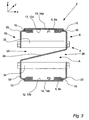
- This embodiment of the system without the corresponding endless carrier chain, i.e. of the corresponding support frame, is depicted in fig. 5 in a perspective view.
- the system of fig. 3 and 4 as depicted shows presence of gliding means 15.
- the gliding means 15 provides a smooth surface upon which the endless carrier chain is supported and/or glides.
- the conveyor system may comprise, at one or more specific locations 23 along the first side of the support frame, a connection between the first main support element 16 and the second auxiliary support element 22. Such connections may also or alternatively in a correspondingly way be present at one or more specific locations 23 along the second side of the support frame.
- a Cartesian coordinate system is included to illustrate the various directions of a conveyor system in an intended use as defined in claim 1.
- the z-direction defines a vertical direction.
- the x-y-plane defines a horizontal plane.
- the longitudinal direction of the support frame accordingly extends along the y-direction "into and out of the paper".
- the present invention relates to a conveyor apparatus comprising a conveyor system according to the invention according to the first aspect of the present invention and drive means for moving the endless carrier chain relative to the support frame.
- the conveyor apparatus and the conveyor system according to the invention may be manufactured using materials and manufacturing processes and techniques well known in the art.
- a person skilled in the art of manufacturing conveyor systems and apparatuses will - on the basis of the present description and the appended claims - know how to manufacture the system and the apparatus according to the first and second aspect of the present invention, respectively.
Landscapes
- Engineering & Computer Science (AREA)
- Mechanical Engineering (AREA)
- Chain Conveyers (AREA)
- Framework For Endless Conveyors (AREA)
- Structure Of Belt Conveyors (AREA)
Description
- The present invention relates in a first aspect to a conveyor system. The present invention relates in a second aspect to a conveyor apparatus comprising a conveyor system according to the first aspect. The present invention relates in a third aspect to the use of a conveyor system according to the first aspect or a conveyor apparatus according to the second aspect for conveying an object.
- Conveyor apparatuses have been known for decades. A conveyor apparatus provides a simple and price efficient was of moving goods or objects within relative small distances, such as within a factory or a processing plant. Accordingly, conveyor apparatuses find use in a variety of different manufacturing and processing industries, such as in the food industry.
- A conveyor apparatus in the general form comprises a support frame supporting an endless carrier chain. The endless carrier chain is mounted on the support frame via at least two bearings, typically arranged at the opposite ends of the support frame. Drive means, such as an electrical motor is typically comprised in the apparatus and the drive means provides motion to the endless carrier chain.
- Within the food industry a food manufacturing company in its processing line often needs to transport a food object in a non-packaged state from one part of the manufacturing plant to another part of the processing plant along the line defined by the various processing steps. For this purpose, use of a conveyor apparatus is an obvious choice.
- A conveyor apparatus due to its construction comprises many hidden surfaces and corners, which may form the foundation for accumulation of debris. Such deposits of debris may in turn lead to accumulation of various microorganisms.
- In the food industry deposits of microorganisms in processing equipment are highly undesirably.
- Moreover, in most countries increasingly strict legislation regulating the requirements to hygiene in food manufacturing industries persistently imposes increasingly strict standards to the hygiene of the equipment used.
- The sources for contamination or soiling of a conveyor apparatus within the food industry are at least two-fold. One source of contamination or soil is associated with deposits from the surrounding environment originating from dust, moist and various particles from the air. Another source of contamination or soil is associated with debris originating from the conveyed objects themselves.
- In order to reduce the extent of the problems associated with deposits from the surrounding environment of dust, moist and various particles in hidden areas in a conveyor apparatus one specific design of a conveyor apparatus has been suggested and put on the marked by the Swedish company Flexlink under the product name XMX. The XMX conveyor apparatus comprises a support frame extending in a longitudinal direction and an endless carrier chain in the form of a multiflexing chain. The multiflexing chain defines an upper part moveable in one direction in relation to said support frame; and a lower part moveable in the opposite direction in relation to said upper part of said carrier chain. The upper part of the multiflexing chain is accommodated in an upper part of the support frame, whereas the lower part of the multiflexing chain is accommodated in a lower part of the support frame. When seen in cross-sectional profile, the longitudinal support frame itself comprises a rectangular element having a first side and a second side. The upper part of the profiles comprises an opening for accommodating the multiflexing chain. Likewise, the lower part of the profile comprises a small opening for accommodating the multiflexing chain. The two sides each comprises an opening extending in a longitudinal direction. These openings provides for inlet of rinsing liquids during a rinsing procedure, yet the support frame of the XMX system is still relatively closed thus reducing the risk of deposits of debris from the surrounding environment. The principle of the XMX system is outlined in
fig. 1 . - A problem associated with the XMX system is that debris that once has deposited on the upper part of the support frame may over time come off and fall down. When such debris falls down it may attach itself to various parts of the lower part of the support frame.
- In order to solve the first problem of XMX system as mentioned above, the Flexlink company has markedet an improved conveyor apparatus; viz. the XMY conveyor apparatus. The XMY conveyor apparatus comprises a support frame extending in a longitudinal direction and an endless carrier chain in the form of a multiflexing chain. The multiflexing chain defines an upper part moveable in one direction in relation to said support frame; and a lower part moveable in the opposite direction in relation to said upper part of said carrier chain. The upper part of the multiflexing chain is accommodated in an upper part of the support frame, whereas the lower part of the multiflexing chain is accommodated in a lower part of the support frame. The upper part of the support frame and the lower part of the support frame are completely separated from each other except at specific points located along the longitudinal direction of the support frame, where the two parts are fastened to each other.
- The upper part of the support frame comprises two side walls at a first side and a second side of the support frame, respectively. The upper part of the support frame thus comprises an opening at the top in which the multiflexing chain is accommodated. The design of the lower part of the support is characteristic in that it has a profile, in a direction perpendicular to the direction of movement of the multiflexing chain, defining an opposite V or U. That is, the lower part of the support frame of the XMY system is complete closed at the top, but comprises a longitudinal opening at the bottom, in which the lower part of the multiflexing chain is accommodated. The principle of the XMY system is outlined in
fig. 2 . - Accordingly, due to the side walls of the upper support part and due to Opposite V or U profile of the bottom part of the support frame of the XMY system, the XMY conveyor apparatus comprises a relatively closed structure which to a great extent reduced the problems of deposition of e.g. dust, moist and various particles from the surrounding environment, and thereby the XMY system also reduced the problems associated with microbiological growth in these particle deposits. Also, the XMY apparatus avoid the problem that debris originating from the upper part of the multiflexing chain deposits onto the lower part of the multiflexing chain.
- As mentioned above, another type of contamination or soiling of the various parts of a conveyor apparatus is present in the situations in which unpackaged food objects are transported on a conveyor apparatus. In such a situation the soiling of the conveyor apparatus originates from the conveyed objects themselves, i.e. the unpackaged food objects.
- Accordingly, in using a conveyor apparatus for transporting unpackaged food objects inevitably results in debris in the form of small parts of the food objects will fall off the food object. Such debris may constitute protein material, carbohydrate material and fats originating from the food object.
- A part of such debris may stick to various parts of the conveyor apparatus where it will decay over time and thereby form the foundation of growth of various species of microorganisms.
- As a consequence, a conveyor apparatus used for transporting unpackaged food objects in a food processing industry needs thorough and frequent cleaning.
- The cleaning procedures are performed manually by a worker washing the conveyor apparatus with a cleansing liquid, brushing the dirty parts with a brush and subsequently rinsing the apparatus with water.
- Although such cleaning procedure may leave the conveyor apparatus in a state that fulfils the requirement set by the legislation as to hygiene, such cleaning procedures are labour heavy and tedious work.
- It is clear that due to the closed structure of the support frame with no or only limited possibility for mechanical cleaning (i.e. by using a brush or the like), neither one of the above referenced XMX system and the XMY system from the company Flexlink is really suitable for conveying unpackaged food objects; this is especially the case in respect of meat products and the like.
- Furthermore,
GB 2 111 011 A - Accordingly, there exists a need for an improved conveyor system which is suitable for conveying unpackaged food products, and which provides for improved possibilities for fast and easy, yet efficient cleaning.
- Those needs are fulfilled according to a first, a second and a third aspect of the present invention.
- In the first aspect, the present invention relates to a conveyor system as defined in claim 1.
- In the second aspect, the present invention relates to a conveyor apparatus comprising a conveyor system according to the first aspect of the present invention and further comprising drive means for moving the endless carrier chain relative to the
support frame 4. - In the third aspect, the present invention relates to a use of a conveyor system according to the first aspect of the present invention or a conveyor apparatus according to the second aspect of the present invention for conveying an object.
- The combination of the technical features of the invention according to a first aspect provides for improved hygiene in conveyor systems because the conveyor system according to the first aspect eliminates the movement of spillage of debris which has been deposited at an upper part of the carrier chain from said upper part of the carrier chain to the lower part of the carrier chain, on the one hand; and on the other hand provides for better access to the various parts of the carrier system with in a cleaning process.
- Such possibilities of improvements in hygiene in a conveyor system is highly desirable in various industries, such as in the food or dairy industries.
-
-
Fig. 1 is a cross-sectional view illustrating the principles of a prior art conveyor system. -
Fig. 2 is a cross-sectional view illustrating the principle of an improved prior art conveyor system. -
Fig. 3 is a cross-sectional view illustrating the principles of the conveyor system according to the first aspect of the present invention. -
Fig. 4 is a cross-sectional view illustrating an embodiment of the conveyor system according to the first aspect of the present invention. -
Fig. 5 is a perspective view illustrating the support frame of the embodiment of the conveyor system offig. 4 . -
Fig. 6 is a cross-sectional view illustrating an embodiment of the conveyor system according to the first aspect of the present invention wherein the conveyor system comprises an endless carrier chain comprising a number of inter-engaging elements flexibly connected to each other. -
Fig. 7 is a perspective view illustrating an embodiment of the conveyor system offig. 6 . - As mentioned above, the present invention in a first aspect relates to a
conveyor system 2 comprising asupport frame 4 and an endless carrier chain 6;
wherein said support frame extends in a longitudinal direction and comprises afirst side 8 and asecond side 10;
wherein said endless carrier chain 6 is arranged upon saidsupport frame 4;
wherein in an orientation intended for use, in which the endless carrier chain 6 is arranged in a horizontal orientation, said endless carrier chain 6 defines an upper part 6a moveable in one direction in relation to said support frame; and alower part 6b moveable in the opposite direction in relation to said upper part of said carrier chain; said endless carrier chain thereby having an inner side 12 and an outer side 14;
wherein said support frame comprises a firstmain support element 16 supporting the upper part of the endless carrier chain at thefirst side 8 of the support frame;
wherein said support frame comprises a secondmain support element 18 supporting the lower part of the endless carrier chain at thesecond side 10 of the support frame;
wherein said support frame comprises a firstauxiliary support element 20 supporting the upper part of the endless carrier chain at thesecond side 10 of the support frame;
wherein said support frame comprises a secondauxiliary support element 22 supporting the lower part of the endless carrier chain at thefirst side 8 of the support frame;
wherein said support frame comprises a shieldingelement 24 extending from thefirst side 8 of the support frame to thesecond side 10 of the support frame in an area A defined between the inner side 12a of the upper part of the endless carrier chain 6 and the inner side 12b of the lower part of the endless carrier chain 6;
wherein said shieldingelement 24 itself, or said shieldingelement 24 in combination with said firstmain support element 16 and/or in combination with said secondmain support element 18 has an extension that blocks a direct access between any point P1 located on the inner side 12a of the upper part of the endless carrier chain 6 and a corresponding point P2 located on the inner side 12b of the lower part of the endless carrier chain, said point P2 being the most proximal point, in relation to the point P1, on the inner side 12b of the lower part of the endless carrier chain. - The conveyor system according to a first aspect of the present invention comprises an endless carrier chain 6 supported
support frame 4 and the support frame having afirst side 8 and asecond side 10. The support frame extends in a longitudinal direction. The term "in a longitudinal direction" in the present description and in the appended claims shall be not be interpreted as necessarily mean that the support frame extends in a linear direction. Rather the term "in a longitudinal direction" shall be interpreted as being the direction along the path of movement defined by the carrier chain. Hence, the carrier chain and consequently the support frame may very well extend in a linear direction, a sideward curved direction, a vertically curved direction or any combination thereof. - In order to define the various directions of the conveyor system, the system is defined with reference to an orientation intended for use in which the endless carrier chain or part thereof is arranged in a horizontal orientation.
- In
fig. 3 and4 the z-direction of the Cartesian coordinate system defines the longitudinal direction; the z-direction is the vertical direction; and the xy-plane is the horizontal plane. - In the orientation as set out in claim 1, said endless carrier chain 6 defines an upper part 6a moveable in one direction in relation to said support frame; and a
lower part 6b moveable in the opposite direction in relation to said upper part of said carrier chain; said endless carrier chain thereby having an inner side 12 and an outer side 14. - The support frame itself comprises a first
main support element 16 supporting the upper part of the endless carrier chain at thefirst side 8 of the support frame; a secondmain support element 18 supporting the lower part of the endless carrier chain at thesecond side 10 of the support frame; a firstauxiliary support element 20 supporting the upper part of the endless carrier chain at thesecond side 10 of the support frame; and a secondauxiliary support element 22 supporting the lower part of the endless carrier chain at thefirst side 8 of the support frame. These support elements serve the purpose of supporting the endless carrier chain along its path of movement. - The advantage of avoiding that debris located and deposited at the upper part of the endless carrier chain or located at the upper part of the support frame finds it way down to the lower part of the endless carrier chain or to the lower part of the support frame is brought about by the shielding
element 24 extending from thefirst side 8 of the support frame to thesecond side 10 of the support frame in an area A defined between the inner side 12a of the upper part of the endless carrier chain 6 and the inner side 12b of the lower part of the endless carrier chain 6. - The shielding element itself, optionally in combination with said first
main support element 16 and/or in combination with said secondmain support element 18 of the conveyor system according to the first aspect of the present invention accordingly having an extension that blocks a direct access between any point P1 located on the inner side 12a of the upper part of the endless carrier chain 6 and a corresponding point P2 located on the inner side 12b of the lower part of the endless carrier chain, said point P2 being the most proximal point, in relation to the point P1, on the inner side 12b of the lower part of the endless carrier chain. - Such blocked path between any point P1 on the located on the inner side 12a of the upper part of the endless carrier chain 6 and a corresponding point P2 located on the inner side 12b of the lower part of the endless carrier chain on the inner side 12b of the lower part of the endless carrier chain prevents that debris falling down will attach itself to the lower part of the endless carrier chain 6 or to the lower part of the support frame.
- It is clear that near the ends of the support frame, the endless carrier chain 6 during use will change direction of movement in one longitudinal direction to a direction of movement in the opposite direction in going from being the upper part 6a of the endless carrier chain to being the
lower part 6b of the endless carrier chain. - It should be noted that the point P1 is located on the innerside 12a of the upper part 6a of the carrier chain at a location where a fixed point located on said carrier chain has not yet initiated/concluded - during use of the carrier chain - its change of direction from one direction to the opposite direction along the longitudinal direction.
- In this way it is clear that the restriction relating to the blocking passage between the point P1 located on the inner side 12a of the upper part of the endless carrier chain 6 and a corresponding point P2 located on the inner side 12b of the lower part of the endless carrier chain applies preferably to the area of the endless carrier chain 6 not being located near the extreme ends of the support frame. As mentioned, near the ends of the support frame, the endless carrier chain 6 will change direction of movement in one longitudinal direction to a direction of movement in the opposite direction in going from being the upper part 6a of the endless carrier chain to being the
lower part 6b of the endless carrier chain. Along the path of change of direction of movement, there may thus be two points located on the inner side 12a of an upper part of the endless carrier chain 6 and located on the inner side 12b of a lower part of the endless carrier chain, respectively, between which no blocking of passage is present. Accordingly, the restriction relating to the blocking passage between the point P1 located on the inner side 12a of the upper part of the endless carrier chain 6 and a corresponding point P2 located on the inner side 12b of the lower part of the endless carrier chain shall be interpreted to apply to all the path of the endless carrier chain except near the two extreme ends E of the carrier chain at which ends a fixed point on the endless carrier chain will change direction from moving in one longitudinal direction to moving in the opposite direction. - It is preferred that the restriction relating to the blocking passage between the point P1 located on the inner side 12a of the upper part of the endless carrier chain 6 and a corresponding point P2 located on the inner side 12b of the lower part of the endless carrier chain shall be interpreted to apply to all the path of the endless carrier chain except at a distance in the longitudinal direction from each of the two extreme ends E of the carrier chain independently selected from the ranges: 50 cm or less, such as 40 cm or less, for example 30 cm or less, such as 25 cm or less, e.g. 20 cm or less, for example 15 cm or less, such as 10 cm or less, or 5 cm or less.
- Hence, in one embodiment of the invention according to the first aspect of the present invention, the shielding
element 24 extends all the way along the longitudinal direction of the endless carrier chain except 50 cm or less, such as 40 cm or less, for example 30 cm or less, such as 25 cm or less, e.g. 20 cm or less, for example 15 cm or less, such as 10 cm or less, or 5 cm or less from the two most extreme ends of said carrier chain. - In another embodiment of the invention according to the first aspect of the present invention, the shielding
element 24 extends all the way between the two most extreme ends of said carrier chain, along the longitudinal direction of the endless carrier chain. - In another embodiment of the invention according to the first aspect of the present invention, the shielding
element 24 extends 75% or more, such as 80% or more, e.g. 85% or more, such as 90% or more or 95% or more of the path the carrier chain defined between the two most extreme ends E of said carrier chain of along the longitudinal direction. - According to the first aspect of the present invention, the
first side 8 of thesupport frame 4 comprises anopening 26, preferably extending alongside essentially all said first side in the longitudinal direction, saidopening 26 providing access to the inner side 12b of thelower part 6b of the endless carrier chain 6; saidopening 26 being defined by the geometry of the firstmain support element 16, the shieldingelement 24 and the secondauxiliary support element 22; and/or saidsecond side 10 of thesupport frame 4 comprises anopening 28, preferably extending alongside essentially all said second side in the longitudinal direction, saidopening 28 providing access to the inner side 12a of the upper part 6a of the endless carrier chain 6; saidopening 28 being defined by the geometry of the secondmain support element 18, the shieldingelement 24 and the secondauxiliary support element 20. - The
openings 26 and/or 28 provides for better access to the interior of the support frame and to the inner side of the endless carrier train, thereby providing improved possibilities for thorough cleaning either by brush or by using pressurised water, such as by using a foam gun. - In a preferred embodiment according to the first aspect of the present invention, the shielding
element 24 at least partly in the area A defines a planar surface extending in an inclined orientation, relative to a horizontal plane, from the first side of the support frame to the second side of the support frame. - Providing the shielding element with an inclined orientation provides for better drain off of rinsing water in a rinsing situation. It is preferred that the inclination of the shielding element is within the range of 5 - 60°, såsom 10 - 55°, e.g. 15 - 50°, for example 20 - 45°, such as 25 - 40° or 30 - 35° in relation to the horizontal plane..
- In another preferred embodiment according to the first aspect of the present invention, the first
main support element 16 at one or morespecific locations 23 along the first side of the support frame is connected to the secondauxiliary support element 22 and/or wherein the secondmain support element 18 at one or morespecific locations 23 along the second side of the support frame is connected to the firstauxiliary support element 20. - Connecting the first main support elements to the second auxiliary support elements at one or more
specific locations 23 along the first side and/or the second side of the support frame provides for a more sturdy construction and thus improves the integrity of the support frame and thereby of the conveyor system. - In yet another preferred embodiment according to the first aspect of the present invention, a
gutter 30 is arranged on the secondmain support element 18 for collection of rinse water in a rinsing situation, saidgutter 30 extending in a longitudinal direction of thesupport frame 4. - Providing the support element with such a gutter enables collection of the rinse water which may be applied to the upper part of the conveyor system in a rinsing and cleaning process.
- In yet another preferred embodiment according to the first aspect of the present invention, one or more transversal
upper struts 32 are arranged at predefined locations along the longitudinal direction ofsupport frame 4; said transversalupper struts 32 connecting the firstmain support element 16 of the first side of the support frame with the firstauxiliary support element 20 of the second side of the support frame. - In yet another preferred embodiment according to the first aspect of the present invention, one or more transversal
lower struts 34 are arranged at predefined locations along the longitudinal direction ofsupport frame 4; said transversallower struts 34 connecting the secondmain support element 18 of the second side of the support frame with the secondauxiliary support element 22 of the first side of the support frame. - Providing the support frame with such upper and/or
lower struts - In yet another preferred embodiment according to the first aspect of the present invention, the first
main support element 16 of the first side of the support frame, the shieldingelement 24 and the secondmain support element 18 of the second side of the support frame are integrally formed in one piece. - Forming these elements in one piece may provide for a cost efficient manufacturing process as well as for less labour house needed in the assembly of the conveyor system. Additionally, this embodiment may provide for a more sturdy construction and thus improves the integrity of the support frame and thereby of the conveyor system.
- In still another preferred embodiment according to the first aspect of the present invention, the profile of at least part of the group of elements comprising the first
main support element 16 of the first side of the support frame, the shieldingelement 24 and the secondmain support element 18 of the second side of the support frame, seen in a transversal direction relative to the longitudinal direction (i.e. in the xz-plane of thesupport frame 4, exhibits a Z-form. - Providing these elements with a profile exhibiting a Z-form has proven to provide efficiency in production of the involved elements as well as such form provides the possibility that the rinsing eater easily can be drained off the shielding
element 24 in a rinsing or cleaning situation. - In still another preferred embodiment according to the first aspect of the present invention, the endless carrier chain to be used in the is a conveyor system selected from the group comprising: a flexible conveyor system, in which the endless carrier chain comprises a number of inter-engaging elements flexibly connected to each other and forming an endless chain; a conveyor belt comprising a polymeric material which may optionally be reinforced, such as by reinforcing wires or a reinforcing web; a lamella belt comprising a number of lamella elements inter-engagingly hinged to one another on one side; a wire belt comprising a number of wires woven together; and any kind of steel belts, such as open or closed steel belts.
- Such carrier chains are know per se from the prior art and they have all proven very useful in the present invention.
- In still another preferred embodiment according to the first aspect of the present invention, one or more of the elements: first
main support element 16, secondmain support element 18, firstauxiliary support element 20, secondauxiliary support element 22, the shieldingelement 24, thegutter 30, one or more of the transversal upper struts 32, one or more transversallower struts 34, are made of steel, such as stainless steel, aluminium, a polymeric material, such as a plastic. - Such materials are well suited for the stated purpose due to their sturdiness, their chemical resistance and anti-corrosion properties.
- In still another preferred embodiment according to the first aspect of the present invention, the conveyor system further comprising brushing means for brushing the endless carrier chain 6 on the outer surface 14a at the upper part of the endless carrier chain 6 and/or on the outer surface 14b, at the lower part of the endless carrier chain 6.
- In still another preferred embodiment according to the first aspect of the present invention, the conveyor system further comprising carrier chain diverting means for diverting or leading said endless carrier chain 6 into the interior of a rinsing container for rinsing the endless carrier chain 6 with a rinsing liquid.
- Such brushing means and chain diverting means provides for easy and even continuously rinsing and cleaning in a processing line even during production and hence during movement under production of the endless carrier chain.
- It is preferred that such brushing means and chain diverting means are provided at the lower part of the endless carrier chain.
- It is preferred that such brushing means and/or diverting means is/are provided with brushing engaging means and/or carrier chain diversion engaging means for reversibly engaging/disengaging said brushing means and/or said diverting means, respectively.
- Such brushing engaging means and/or carrier chain diversion engaging means provides for easy and swift engagement and disengagement of the means and chain diverting means from a rinsing/cleaning operation of the carrier chain to a non-rinsing/non-cleaning operation of the carrier chain.
- In one embodiment of the first aspect of the present invention, two or more conveyor systems according to any of the claims 1 - X arranged on top of each other, such as 2, 3, 4, 5, 6, 7 or 8 conveyor systems arranged on top of each other.
- Such arrangement is advantageous in that space is saved in a processing line of a manufacturing company.
- The conveyor system according to the first aspect of the present invention is useful in a conveyor apparatus. Accordingly, the present invention according to the second aspect of the present invention relates to a conveyor apparatus comprising a conveyor system according to the first aspect of the present invention and additionally drive means for moving the endless carrier chain relative to the
support frame 4. - Such drive means may be an electrical motor, a hydraulic motor, an air-driven motor or a vacuum motor.
- In a third aspect, the present invention relates to the use of a conveyor system according to the first aspect of the present invention or use of a conveyor apparatus according to the second aspect of the present invention for conveying an object.
- In a preferred embodiment of the use according to the third aspect, the object is a food or a food precursor.
- It is especially useful to use the invention of the first and second aspect of the present invention within the food or dairy industry because high standards of hygiene are required within these industries.
- In the following, the present invention will be described with reference to the figures.
-
Fig. 3 illustrates in a cross-sectional view of an embodiment of the first aspect of the present invention.Fig. 3 shows thesupport frame 4 having afirst side 8 and asecond side 10. The support frame extends in a longitudinal direction (i.e. in the y-direction. The support frame supports an endless carrier chain 6. The carrier chain 6 comprises an upper part 6a and alower part 6b. In the embodiment offig. 3 the endless carrier chain comprises a conveyor belt comprising a polymeric material which may optionally be reinforced, such as by reinforcing wires or a reinforcing web. However, any other type of endless carrier chains may be applies as well, such as those defined in the claims. - The support frame comprises a first
main support element 16 supporting the upper part of the endless carrier chain at thefirst side 8 of the support frame; wherein said support frame comprises a secondmain support element 18 supporting the lower part of the endless carrier chain at thesecond side 10 of the support frame; wherein said support frame comprises a firstauxiliary support element 20 supporting the upper part of the endless carrier chain at thesecond side 10 of the support frame; wherein said support frame comprises a secondauxiliary support element 22 supporting the lower part of the endless carrier chain at thefirst side 8 of the support frame. - Support struts 26 and 28 serves as supporting and strengthening the integrity of the support frame.
- The support frame comprises a shielding
element 24 extending from thefirst side 8 of the support frame to thesecond side 10 of the support frame in an area A defined between the inner side 12a of the upper part of the endless carrier chain 6 and the inner side 12b of the lower part of the endless carrier chain 6. The shieldingelement 24 is arranged in such a way that the shieldingelement 24 itself, or said shieldingelement 24 in combination with said firstmain support element 16 and/or in combination with said secondmain support element 18 having an extension that blocks a direct access between any point P1 located on the inner side 12a of the upper part of the endless carrier chain 6 and a corresponding point P2 located on the inner side 12b of the lower part of the endless carrier chain, said point P2 being the most proximal point, in relation to the point P1, on the inner side 12b of the lower part of the endless carrier chain. - In
fig. 3 the shielding element has a preferred Z-like form. - It is clearly seen from
fig. 1 that in a situation where debris or other kind of dirt, which has been deposited in the upper part of the support frame and/or the upper part of the endless carrier chain, comes off, such debris or dirt is prevented from entering the inside of the lower part of the support frame and/or the lower part of the endless carrier chain by virtue of the shieldingelement 24 which prevents such entrance. - The same applies during use in a processing line. Once the conveyed product or object, such as a food or food precursor, gives of a little part of material this part may stick to the upper part of the support frame and/or the upper part of the endless carrier chain. However, such material which has fallen off the conveyed product or object will never enter the lower part of the support frame and/or the lower part of the endless carrier chain, because the shielding
element 24 will make prevent that this fallen off object or product will enter the lower part of the support frame and/or the lower part of the endless carrier chain. - Furthermore, the
openings - In a rinsing or cleaning situation, the same principle of the shielding
element 24 applies. Upon rinsing of the upper part of the support frame and/or the upper part of the endless carrier chain, the rinsing liquid used, such as water or detergent/water will by virtue of the shielding element by directed away from the lower part of the support frame and/or the lower part of the endless carrier chain so that these part will not be contaminated with dirty rinsing water. - All in all the conveyor system of the first embodiment as shown in
fig. 3 provides for an improved hygiene. - This is not the case in respect of the prior art systems shown in
fig 1 and 2. Fig. 1 shows in a cross-sectional view an example of a prior art conveyor system (the XMX system of Flexlink mentioned in the introduction of the present application. - The prior art system of
fig. 1 comprises a carrier frame which in turn comprises afirst side part 106 and asecond side part 108. The two side parts are spaced apart so that they together forms an upper longitudinal opening upon which thecarrier chain 102 is supported, and a lower longitudinal opening supporting thelower carrier chain 104. - The system of
fig. 1 does not prevent debris from the upper part of the system to reach the lower part of the system. Further, the system offig. 1 does not provide good access to the interior of the conveyor system. - An improvement to the system of
fig. 1 is illustrated infig. 2 . This system corresponds to the XMY system of Flexlink mentioned in the introduction of the present application. -
Fig. 2 shows aconveyor system 200 comprising anupper part 220 and alower part 210. - The upper part of the
endless carrier chain 202 is accommodated in an upper part of thesupport frame 220, whereas the lower part of theendless carrier chain 204 is accommodated in a lower part of thesupport frame 230. The upper part of the support frame and the lower part of the support frame are completely separated from each other except at specific points located along the longitudinal direction of the support frame, where the two parts are fastened to each other bybrackets 214. - The upper part of the support frame comprises two side walls 206,208 at a first side and a second side of the support frame, respectively. The upper part of the support frame thus comprises an opening at the top in which the
endless carrier chain 202 is accommodated. As seen infig. 2 the lower part of thesupport frame 230 has a profile defining an opposite V or U. That is, the lower part of the support frame of the system offig. 2 is completely closed at the top, but comprises a longitudinal opening at the bottom, in which the lower part of theendless carrier chain 204 is accommodating. - The prior art system of
fig. 2 avoids the problem that debris originating from the upper part of the endless carrier chain deposits onto the lower part of the endless carrier chain. - However, due to its closed structure, and the poor access to the interior of the various parts of the prior art conveyor system of
fig 2 , cleaning and rinsing operations in this system is difficult and restricted. -
Fig. 4 shows a cross-sectional embodiment of a conveyor system according to the present invention. In this embodiment the conveyor system is provided with agutter 30 for collecting debris and/or rinsing liquids originating from the upper part of the conveyor system and lead to the saidgutter 30 by the shieldingelement 24. This embodiment of the system without the corresponding endless carrier chain, i.e. of the corresponding support frame, is depicted infig. 5 in a perspective view. The system offig. 3 and4 as depicted shows presence of gliding means 15. The gliding means 15 provides a smooth surface upon which the endless carrier chain is supported and/or glides. - In
fig 6 and 7 are illustrated in a cross-sectional view and a perspective view respectively an embodiment of the conveyor system according to the first aspect of the present invention. In these figures it is illustrated that the conveyor system may comprise, at one or morespecific locations 23 along the first side of the support frame, a connection between the firstmain support element 16 and the secondauxiliary support element 22. Such connections may also or alternatively in a correspondingly way be present at one or morespecific locations 23 along the second side of the support frame. - In
fig. 3 and4 a Cartesian coordinate system is included to illustrate the various directions of a conveyor system in an intended use as defined in claim 1. Hence, the z-direction defines a vertical direction. The x-y-plane defines a horizontal plane. InFigs. 1, 2 ,3 ,4 and6 the longitudinal direction of the support frame accordingly extends along the y-direction "into and out of the paper". - In a second aspect the present invention relates to a conveyor apparatus comprising a conveyor system according to the invention according to the first aspect of the present invention and drive means for moving the endless carrier chain relative to the support frame.
- The conveyor apparatus and the conveyor system according to the invention may be manufactured using materials and manufacturing processes and techniques well known in the art. A person skilled in the art of manufacturing conveyor systems and apparatuses will - on the basis of the present description and the appended claims - know how to manufacture the system and the apparatus according to the first and second aspect of the present invention, respectively.
- It will be understood that the invention is not limited to the particular examples described above but may be designed in a multitude of varieties within the scope of the invention, as specified in the claims.
-
- 2. Conveyor system
- 4. Support frame
- 6. Endless carrier chain
- 6a. Upper part of endless carrier chain
- 6b. Lower part of endless carrier chain
- 8. First side of support frame
- 10. Second side of support frame.
- 12. Inner side of endless carrier chain
- 12a. Inner side of the upper part of endless carrier chain
- 12b. Inner side of the lower part of endless carrier chain
- 14. Outer side of endless carrier chain
- 14a. Outer side of the upper part of endless carrier chain
- 14b. Outer side of the lower part of endless carrier chain
- 15. Gliding means
- 16. First main support element
- 18. Second main support element
- 20. First auxiliary support element
- 22. Second auxiliary support element
- 23. Location at which a main support element is connected to the an auxiliary support element.
- 24. Shielding element
- 26. Opening at first side of support frame
- 28. Opening at second side of support frame
- 30. Gutter
- 32. Transversal upper struts
- 34. Transversal lower struts
- 100. Conveyor system of prior art
- 102. Upper part of endless drive chain
- 104. Lower part of endless drive chain
- 106. First side of support frame
- 108. Second side of support frame
- 200. Conveyor system of prior art
- 202. Upper part of endless drive chain
- 204. Lower part of endless drive chain
- 206. First side of upper support frame
- 208. Second side of upper support frame
- 210. First side of lower support frame
- 112. Second side of lower support frame
- 214. Bracket connecting upper support frame with lower support frame
- 220. Upper support frame
- 230. Lower support frame
Claims (17)
- A conveyor system (2) comprising a support frame (4) and an endless carrier chain (6);
wherein said support frame extends in a longitudinal direction and comprises a first side (8) and a second side (10);
wherein said endless carrier chain (6) is arranged upon said support frame (4);
wherein in an orientation intended for use, in which the endless carrier chain (6) is arranged in a horizontal orientation, said endless carrier chain (6) defines an upper part (6a) moveable in one direction in relation to said support frame; and a lower part (6b) moveable in the opposite direction in relation to said upper part of said carrier chain; said endless carrier chain thereby having an inner side (12) and an outer side (14);
wherein said support frame comprises a first main support element (16) supporting the upper part of the endless carrier chain at the first side (8) of the support frame;
wherein said support frame comprises a second main support element (18) supporting the lower part of the endless carrier chain at the second side (10) of the support frame;
wherein said support frame comprises a first auxiliary support element (20) supporting the upper part of the endless carrier chain at the second side (10) of the support frame;
wherein said support frame comprises a second auxiliary support element (22) supporting the lower part of the endless carrier chain at the first side (8) of the support frame;
wherein said support frame comprises a shielding element (24) extending from the first side (8) of the support frame to the second side (10) of the support frame in an area (A) defined between the inner side (12a) of the upper part of the endless carrier chain (6) and the inner side (12b) of the lower part of the endless carrier chain (6); and
wherein said shielding element (24) itself, or said shielding element (24) in combination with said first main support element (16) and/or in combination with said second main support element (18) has an extension that blocks a direct access between any point P1 located on the inner side (12a) of the upper part of the endless carrier chain (6) and a corresponding point P2 located on the inner side (12b) of the lower part of the endless carrier chain, said point P2 being the most proximal point, in relation to the point P1, on the inner side (12b) of the lower part of the endless carrier chain;
characterised in that
the first side (8) of the support frame (4) comprises an opening (26), preferably extending alongside essentially all said first side in the longitudinal direction, said opening (26) providing access to the inner side (12b) of the lower part (6b) of the endless carrier chain (6); said opening (26) being defined by the geometry of the first main support element (16), the shielding element (24) and the second auxiliary support element (22); and/or
in that the second side (10) of the support frame (4) comprises an opening (28), preferably extending alongside essentially all said second side in the longitudinal direction, said opening (28) providing access to the inner side (12a) of the upper part (6a) of the endless carrier chain (6); said opening (28) being defined by the geometry of the second main support element (18), the shielding element (24) and the first auxiliary support element (20). - A conveyor system according to claim 1, wherein said shielding element (24) at least partly in the area A defines a planar surface extending in an inclined orientation, relative to a horizontal plane, from the first side of the support frame to the second side of the support frame.
- A conveyor system according to claim 1 or 2, wherein the first main support element (16) at one or more specific locations (23) along the first side of the support frame is connected to the second auxiliary support element (22) and/or wherein the second main support element (18) at one or more specific locations (23) along the second side of the support frame is connected to the first auxiliary support element (20).
- A conveyor system according to any of the claims 1 - 3, wherein a gutter (30) is arranged on the second main support element (18) for collection of rinse water in a rinsing situation, said gutter (30) extending in a longitudinal direction of the support frame (4).
- A conveyor system according to any of the claims 1 - 4, wherein one or more transversal upper struts (32) are arranged at predefined locations along the longitudinal direction of support frame (4); said transversal upper struts (32) connecting the first main support element (16) of the first side of the support frame with the first auxiliary support element (20) of the second side of the support frame.
- A conveyor system according to any of the claims 1 - 5, wherein one or more transversal lower struts (34) are arranged at predefined locations along the longitudinal direction of support frame (4); said transversal lower struts (34) connecting the second main support element (18) of the second side of the support frame with the second auxiliary support element (22) of the first side of the support frame.
- A conveyor system according to any of the claims 1 - 6, wherein the first main support element (16) of the first side of the support frame, the shielding element (24) and the second main support element (18) of the second side of the support frame are integrally formed in one piece.
- A conveyor system according to any of the claims 1 - 7, wherein the profile of at least part of the group of elements comprising the first main support element (16) of the first side of the support frame, the shielding element (24) and the second main support element (18) of the second side of the support frame, seen in a transversal direction relative to the longitudinal direction of the support frame (4), exhibits a Z-form.
- A conveyor system according to any of the claims 1 - 8 wherein the endless carrier chain is a carrier chain selected from the group comprising: a flexible conveyor system, in which the endless carrier chain comprises a number of inter-engaging elements flexibly connected to each other and forming an endless chain; a conveyor belt comprising a polymeric material which may optionally be reinforced, such as by reinforcing wires or a reinforcing web; a lamella belt comprising a number of lamella elements inter-engagingly hinged to one another on one side; a wire belt comprising a number of wires woven together; any kind of steel belts, such as open or closed steel belts.
- A conveyor system according to any of the claims 1 - 9, wherein one or more of the elements: first main support element (16), second main support element (18), first auxiliary support element (20), second auxiliary support element (22), the shielding element (24), the gutter (30), one or more of the transversal upper struts (32), one or more transversal lower struts (34), are made of steel, such as stainless steel, aluminium, a polymeric material, such as a plastic.
- A conveyor system according to any of the claims 1 - 10, further comprising brushing means for brushing the endless carrier chain (6) on the outer surface (14a) at the upper part of the endless carrier chain (6) and/or on the outer surface (14b), at the lower part of the endless carrier chain (6).
- A conveyor system according to any of the claims 1 - 11, further comprising carrier chain diverting means for diverting or leading said endless carrier chain (6) into the interior of a rinsing container for rinsing the endless carrier chain (6) with a rinsing liquid.
- A conveyor system according to any of the claims 11 or 12, wherein said brushing means and/or diverting means is/are provided with brushing engaging means and/or carrier chain diversion engaging means for reversibly engaging/disengaging said brushing means and/or diverting means, respectively.
- A conveyor system comprising two or more conveyor systems according to any of the claims 1 - 13 arranged on top of each other, such as 2, 3, 4, 5, 6, 7 or 8 conveyor systems arranged on top of each other.
- A conveyor apparatus comprising a conveyor system according to any of the claims 1 - 14 and drive means for moving the endless carrier chain relative to the support frame (4).
- Use of a conveyor system according to any of the claims 1 - 14 or a conveyor apparatus according to claim 15 for conveying an object.
- Use according to claim 16, wherein the object is a food or a food precursor.
Priority Applications (1)
| Application Number | Priority Date | Filing Date | Title |
|---|---|---|---|
| PL11779333T PL2635511T3 (en) | 2010-11-02 | 2011-10-26 | Conveyor |
Applications Claiming Priority (2)
| Application Number | Priority Date | Filing Date | Title |
|---|---|---|---|
| DKPA201000990A DK177306B1 (en) | 2010-11-02 | 2010-11-02 | Conveyor |
| PCT/DK2011/000118 WO2012059101A1 (en) | 2010-11-02 | 2011-10-26 | Conveyor |
Publications (2)
| Publication Number | Publication Date |
|---|---|
| EP2635511A1 EP2635511A1 (en) | 2013-09-11 |
| EP2635511B1 true EP2635511B1 (en) | 2014-09-24 |
Family
ID=44910082
Family Applications (1)
| Application Number | Title | Priority Date | Filing Date |
|---|---|---|---|
| EP11779333.1A Active EP2635511B1 (en) | 2010-11-02 | 2011-10-26 | Conveyor |
Country Status (17)
| Country | Link |
|---|---|
| US (1) | US8851277B2 (en) |
| EP (1) | EP2635511B1 (en) |
| JP (1) | JP5923096B2 (en) |
| KR (1) | KR20130127438A (en) |
| CN (1) | CN103189288B (en) |
| AU (1) | AU2011325561B2 (en) |
| BR (1) | BR112013007043B1 (en) |
| CA (1) | CA2816110C (en) |
| DK (1) | DK177306B1 (en) |
| ES (1) | ES2526322T3 (en) |
| HK (1) | HK1183469A1 (en) |
| MX (1) | MX339700B (en) |
| MY (1) | MY170334A (en) |
| NZ (1) | NZ610078A (en) |
| PL (1) | PL2635511T3 (en) |
| PT (1) | PT2635511E (en) |
| WO (1) | WO2012059101A1 (en) |
Families Citing this family (8)
| Publication number | Priority date | Publication date | Assignee | Title |
|---|---|---|---|---|
| US8662292B2 (en) * | 2011-09-26 | 2014-03-04 | Service Industries, LLC | Conveyor belt assembly |
| WO2015041591A1 (en) * | 2013-09-18 | 2015-03-26 | Flexlink Components Ab | Guide rail |
| EP2998248B1 (en) * | 2014-09-22 | 2017-03-01 | Avancon Sa | Conveying system |
| JP2018505056A (en) * | 2014-12-23 | 2018-02-22 | エフルエント フリー デザリネイション コーポレイション | Improved seawater desalination method and apparatus without runoff |
| KR200485037Y1 (en) * | 2016-06-29 | 2017-11-22 | 세창인터내쇼날(주) | Frame for a conveyor frame |
| US11618035B2 (en) | 2017-11-17 | 2023-04-04 | Alan Lewis Fitzmaurice | Endless maceration conveyor assembly with juice deflector |
| CN107955870A (en) * | 2018-01-26 | 2018-04-24 | 湖南高致精工机械有限公司 | A kind of waste heat quenching device suitable for belt track iron tooth workpiece |
| CN109723086B (en) * | 2019-03-05 | 2020-12-22 | 安徽省华腾农业科技有限公司经开区分公司 | Use method of magnetic pushing equipment for curve-segment steel reinforcement cage pushing device |
Family Cites Families (32)
| Publication number | Priority date | Publication date | Assignee | Title |
|---|---|---|---|---|
| US3848732A (en) * | 1972-05-01 | 1974-11-19 | Continental Can Co | Riveted modular conveyor |
| US3824067A (en) * | 1973-03-20 | 1974-07-16 | Lehara Inc Werner | Oven conveyor and method |
| US4013167A (en) * | 1975-05-21 | 1977-03-22 | Custom Fabricators, Inc. | Conveyor support structure |
| US3998321A (en) * | 1975-09-15 | 1976-12-21 | Schultz Edward D | Conveyor wash device |
| SE428201B (en) * | 1980-02-14 | 1983-06-13 | Skf Ab | TRANSPORTER INCLUDING A NUMBER IN AN ENDLESS BAND AFTER EACH JOINED BODIES PROVIDED TO BE PROVIDED AND MANAGED |
| SE8107357L (en) * | 1981-12-09 | 1983-06-10 | Skf Ab | TRANSPORTOR INCLUDING EASY MOUNTED BALL SECTIONS |
| DE3437049A1 (en) * | 1983-10-11 | 1985-04-25 | Santrade Ltd., Luzern | CONVEYOR |
| SE8405826L (en) * | 1984-11-20 | 1986-05-21 | Skf Ab | TRANSPORTATION DEVICE WITH MULTIPLE TRANSPORTOR Beam |
| US5220989A (en) * | 1989-06-07 | 1993-06-22 | Texas A&M University | Modular tray accumulator system |
| US5186314A (en) * | 1990-09-28 | 1993-02-16 | Simplimatic Engineering Company | Conveyor system |
| WO1992011191A1 (en) * | 1990-12-20 | 1992-07-09 | Ideas In Motion Pty. Ltd. | Modular conveyor system |
| JPH057378U (en) * | 1991-07-05 | 1993-02-02 | 株式会社クボタ | Crop sorting equipment |
| US5178263A (en) * | 1991-11-27 | 1993-01-12 | International Paper Company | Modular track section for an endless conveyor |
| JP2562229Y2 (en) * | 1993-03-23 | 1998-02-10 | 麒麟麦酒株式会社 | Low noise type conveyor |
| US5605219A (en) * | 1994-09-12 | 1997-02-25 | Avtec Industries, Inc. | Article conveyor system |
| JP3304695B2 (en) * | 1995-07-07 | 2002-07-22 | 株式会社ダイフク | Conveyor frame |
| US5649616A (en) | 1996-04-11 | 1997-07-22 | Stecklow; Richard L. | Conveyor chain cleaning apparatus |
| US5788056A (en) * | 1996-08-12 | 1998-08-04 | Tekno, Inc. | Conveyor frame with removable tracks retained by spring pins |
| US5860511A (en) | 1996-11-15 | 1999-01-19 | Rexnord Corporation | Conveyor guide rail supports |
| JP3801765B2 (en) * | 1998-02-09 | 2006-07-26 | 松下電器産業株式会社 | Reflow furnace |
| US6401912B1 (en) * | 1999-10-26 | 2002-06-11 | Clarence L. Bandy, Jr. | Conveyor pan assembly with replaceable deck |
| SE516849C2 (en) | 2000-07-05 | 2002-03-12 | Flexlink Components Ab | Sliding rail assembly for conveyor |
| US6422382B1 (en) * | 2000-09-01 | 2002-07-23 | Dorner Mfg. Corp. | Conveyor incorporating a modular frame construction |
| SE519179C2 (en) * | 2001-06-13 | 2003-01-28 | Flexlink Components Ab | Conveyor and connecting piece to conveyor beam sides |
| CN2487705Y (en) * | 2001-06-14 | 2002-04-24 | 区永辉 | Antistatic dust-proof caterpillar conveying line |
| SE519706C2 (en) * | 2001-08-03 | 2003-04-01 | Flexlink Components Ab | Work module for connection to a main conveyor in a conveyor system comprising an endless chain, and a transport unit |
| SE521815C2 (en) * | 2002-04-19 | 2003-12-09 | Flexlink Components Ab | Method and blank for the manufacture of a curved curve element, curved curve element, curve unit comprising a curved curve element and conveyor path comprising such a curve unit. |
| US6848572B1 (en) * | 2003-11-10 | 2005-02-01 | Danville Automation Holdings Llc | Modular conveyor system |
| RU2007110220A (en) * | 2004-09-21 | 2008-09-27 | ВАЙБР-ТЕК ЭлЭлСи (US) | DEVICE AND METHOD FOR CLEANING THE CONVEYOR |
| PL379034A1 (en) * | 2006-02-22 | 2007-09-03 | International Tobacco Machinery Poland Spółka Z Ograniczoną Odpowiedzialnością | Method and device for washing the conveyor belts |
| ATE550138T1 (en) * | 2007-09-14 | 2012-04-15 | Flexlink Components Ab | LIFTING DEVICE FOR A CONVEYOR SYSTEM, CONVEYOR SYSTEM AND METHOD |
| US8662292B2 (en) * | 2011-09-26 | 2014-03-04 | Service Industries, LLC | Conveyor belt assembly |
-
2010
- 2010-11-02 DK DKPA201000990A patent/DK177306B1/en active
-
2011
- 2011-10-26 AU AU2011325561A patent/AU2011325561B2/en active Active
- 2011-10-26 JP JP2013535280A patent/JP5923096B2/en active Active
- 2011-10-26 CA CA2816110A patent/CA2816110C/en active Active
- 2011-10-26 NZ NZ610078A patent/NZ610078A/en unknown
- 2011-10-26 ES ES11779333.1T patent/ES2526322T3/en active Active
- 2011-10-26 US US13/824,257 patent/US8851277B2/en active Active
- 2011-10-26 KR KR1020137009745A patent/KR20130127438A/en not_active Application Discontinuation
- 2011-10-26 MX MX2013004728A patent/MX339700B/en active IP Right Grant
- 2011-10-26 PL PL11779333T patent/PL2635511T3/en unknown
- 2011-10-26 WO PCT/DK2011/000118 patent/WO2012059101A1/en active Application Filing
- 2011-10-26 EP EP11779333.1A patent/EP2635511B1/en active Active
- 2011-10-26 CN CN201180051455.0A patent/CN103189288B/en active Active
- 2011-10-26 MY MYPI2013700630A patent/MY170334A/en unknown
- 2011-10-26 PT PT117793331T patent/PT2635511E/en unknown
- 2011-10-26 BR BR112013007043-9A patent/BR112013007043B1/en active IP Right Grant
-
2013
- 2013-09-19 HK HK13110763.9A patent/HK1183469A1/en not_active IP Right Cessation
Also Published As
| Publication number | Publication date |
|---|---|
| EP2635511A1 (en) | 2013-09-11 |
| US8851277B2 (en) | 2014-10-07 |
| WO2012059101A1 (en) | 2012-05-10 |
| JP5923096B2 (en) | 2016-05-24 |
| BR112013007043B1 (en) | 2021-04-20 |
| DK201000990A (en) | 2012-05-03 |
| JP2013545688A (en) | 2013-12-26 |
| NZ610078A (en) | 2014-03-28 |
| CA2816110A1 (en) | 2012-05-10 |
| AU2011325561B2 (en) | 2015-03-12 |
| HK1183469A1 (en) | 2013-12-27 |
| BR112013007043A2 (en) | 2016-06-14 |
| ES2526322T3 (en) | 2015-01-09 |
| AU2011325561A1 (en) | 2013-05-23 |
| MX2013004728A (en) | 2013-07-12 |
| US20130180833A1 (en) | 2013-07-18 |
| CN103189288B (en) | 2016-02-17 |
| CN103189288A (en) | 2013-07-03 |
| PL2635511T3 (en) | 2015-03-31 |
| PT2635511E (en) | 2014-12-31 |
| KR20130127438A (en) | 2013-11-22 |
| MY170334A (en) | 2019-07-18 |
| CA2816110C (en) | 2019-03-19 |
| MX339700B (en) | 2016-05-18 |
| DK177306B1 (en) | 2012-11-12 |
Similar Documents
| Publication | Publication Date | Title |
|---|---|---|
| EP2635511B1 (en) | Conveyor | |
| US5746302A (en) | Apparatus for cleaning conveyors | |
| US5316134A (en) | Conveyor guidetrack segment | |
| US9604789B2 (en) | Guide rail | |
| CA1158578A (en) | Metal trough and its method of manufacture | |
| EP0201746B1 (en) | Cleaning apparatus for articles moving on a conveyor | |
| JP6429041B2 (en) | Conveyor chain support | |
| KR101648797B1 (en) | Automatic box washing machine | |
| US4619358A (en) | Conveyor assembly | |
| CN212069838U (en) | Full-automatic spray dryer for transfer box of metering appliance | |
| CN110949928B (en) | Overhead storage system for tobacco raw material logistics | |
| CN221069805U (en) | Automatic feeder | |
| CN209506137U (en) | A kind of finished product feedstuff flowing bugduster apparatus | |
| US20140246058A1 (en) | Apparatus for washing and drying totes and related methods | |
| CN210794604U (en) | Novel screw conveyer | |
| CN107777385A (en) | A kind of conveyer dust collect plant | |
| CN109230337B (en) | Commercial combination formula tableware conveying system | |
| JPS628907A (en) | Conveyor for pulverulent body | |
| RU2042322C1 (en) | Installation for removal of manure from under slatted floors in pigsties | |
| JPS63165213A (en) | Automatic cleaning device for pallet | |
| DE102016014578A1 (en) | Method and apparatus for drying carriers | |
| IT1247095B (en) | Device for conveying parts during painting operations, having a substantially horizontal extension | |
| JPS62192198A (en) | Method for washing carpet | |
| DE8512960U1 (en) | Washing device for cleaning workpiece carriers moving on conveyor tracks | |
| DE2362095B1 (en) | Device for feeding bulk goods onto a belt conveyor |
Legal Events
| Date | Code | Title | Description |
|---|---|---|---|
| PUAI | Public reference made under article 153(3) epc to a published international application that has entered the european phase |
Free format text: ORIGINAL CODE: 0009012 |
|
| 17P | Request for examination filed |
Effective date: 20130523 |
|
| AK | Designated contracting states |
Kind code of ref document: A1 Designated state(s): AL AT BE BG CH CY CZ DE DK EE ES FI FR GB GR HR HU IE IS IT LI LT LU LV MC MK MT NL NO PL PT RO RS SE SI SK SM TR |
|
| DAX | Request for extension of the european patent (deleted) | ||
| GRAP | Despatch of communication of intention to grant a patent |
Free format text: ORIGINAL CODE: EPIDOSNIGR1 |
|
| INTG | Intention to grant announced |
Effective date: 20140415 |
|
| GRAS | Grant fee paid |
Free format text: ORIGINAL CODE: EPIDOSNIGR3 |
|
| GRAA | (expected) grant |
Free format text: ORIGINAL CODE: 0009210 |
|
| AK | Designated contracting states |
Kind code of ref document: B1 Designated state(s): AL AT BE BG CH CY CZ DE DK EE ES FI FR GB GR HR HU IE IS IT LI LT LU LV MC MK MT NL NO PL PT RO RS SE SI SK SM TR |
|
| REG | Reference to a national code |
Ref country code: GB Ref legal event code: FG4D |
|
| REG | Reference to a national code |
Ref country code: CH Ref legal event code: EP |
|
| REG | Reference to a national code |
Ref country code: AT Ref legal event code: REF Ref document number: 688519 Country of ref document: AT Kind code of ref document: T Effective date: 20141015 |
|
| REG | Reference to a national code |
Ref country code: IE Ref legal event code: FG4D |
|
| REG | Reference to a national code |
Ref country code: DE Ref legal event code: R096 Ref document number: 602011010163 Country of ref document: DE Effective date: 20141106 |
|
| REG | Reference to a national code |
Ref country code: SE Ref legal event code: TRGR |
|
| REG | Reference to a national code |
Ref country code: CH Ref legal event code: NV Representative=s name: MICHELI AND CIE SA, CH Ref country code: PT Ref legal event code: SC4A Free format text: AVAILABILITY OF NATIONAL TRANSLATION Effective date: 20141217 |
|
| REG | Reference to a national code |
Ref country code: ES Ref legal event code: FG2A Ref document number: 2526322 Country of ref document: ES Kind code of ref document: T3 Effective date: 20150109 |
|
| REG | Reference to a national code |
Ref country code: NL Ref legal event code: T3 |
|
| PG25 | Lapsed in a contracting state [announced via postgrant information from national office to epo] |
Ref country code: LT Free format text: LAPSE BECAUSE OF FAILURE TO SUBMIT A TRANSLATION OF THE DESCRIPTION OR TO PAY THE FEE WITHIN THE PRESCRIBED TIME-LIMIT Effective date: 20140924 |
|
| REG | Reference to a national code |
Ref country code: NO Ref legal event code: T2 Effective date: 20140924 |
|
| REG | Reference to a national code |
Ref country code: EE Ref legal event code: FG4A Ref document number: E010010 Country of ref document: EE Effective date: 20141217 |
|
| REG | Reference to a national code |
Ref country code: LT Ref legal event code: MG4D |
|
| PG25 | Lapsed in a contracting state [announced via postgrant information from national office to epo] |
Ref country code: HR Free format text: LAPSE BECAUSE OF FAILURE TO SUBMIT A TRANSLATION OF THE DESCRIPTION OR TO PAY THE FEE WITHIN THE PRESCRIBED TIME-LIMIT Effective date: 20140924 Ref country code: CY Free format text: LAPSE BECAUSE OF FAILURE TO SUBMIT A TRANSLATION OF THE DESCRIPTION OR TO PAY THE FEE WITHIN THE PRESCRIBED TIME-LIMIT Effective date: 20140924 Ref country code: LV Free format text: LAPSE BECAUSE OF FAILURE TO SUBMIT A TRANSLATION OF THE DESCRIPTION OR TO PAY THE FEE WITHIN THE PRESCRIBED TIME-LIMIT Effective date: 20140924 Ref country code: RS Free format text: LAPSE BECAUSE OF FAILURE TO SUBMIT A TRANSLATION OF THE DESCRIPTION OR TO PAY THE FEE WITHIN THE PRESCRIBED TIME-LIMIT Effective date: 20140924 |
|
| REG | Reference to a national code |
Ref country code: GR Ref legal event code: EP Ref document number: 20140402544 Country of ref document: GR Effective date: 20150128 |
|
| REG | Reference to a national code |
Ref country code: PL Ref legal event code: T3 |
|
| PG25 | Lapsed in a contracting state [announced via postgrant information from national office to epo] |
Ref country code: RO Free format text: LAPSE BECAUSE OF FAILURE TO SUBMIT A TRANSLATION OF THE DESCRIPTION OR TO PAY THE FEE WITHIN THE PRESCRIBED TIME-LIMIT Effective date: 20140924 Ref country code: IS Free format text: LAPSE BECAUSE OF FAILURE TO SUBMIT A TRANSLATION OF THE DESCRIPTION OR TO PAY THE FEE WITHIN THE PRESCRIBED TIME-LIMIT Effective date: 20150124 Ref country code: SK Free format text: LAPSE BECAUSE OF FAILURE TO SUBMIT A TRANSLATION OF THE DESCRIPTION OR TO PAY THE FEE WITHIN THE PRESCRIBED TIME-LIMIT Effective date: 20140924 |
|
| REG | Reference to a national code |
Ref country code: DE Ref legal event code: R097 Ref document number: 602011010163 Country of ref document: DE |
|
| PG25 | Lapsed in a contracting state [announced via postgrant information from national office to epo] |
Ref country code: MC Free format text: LAPSE BECAUSE OF FAILURE TO SUBMIT A TRANSLATION OF THE DESCRIPTION OR TO PAY THE FEE WITHIN THE PRESCRIBED TIME-LIMIT Effective date: 20140924 |
|
| PG25 | Lapsed in a contracting state [announced via postgrant information from national office to epo] |
Ref country code: DK Free format text: LAPSE BECAUSE OF FAILURE TO SUBMIT A TRANSLATION OF THE DESCRIPTION OR TO PAY THE FEE WITHIN THE PRESCRIBED TIME-LIMIT Effective date: 20140924 Ref country code: BG Free format text: LAPSE BECAUSE OF NON-PAYMENT OF DUE FEES Effective date: 20150630 |
|
| PLBE | No opposition filed within time limit |
Free format text: ORIGINAL CODE: 0009261 |
|
| STAA | Information on the status of an ep patent application or granted ep patent |
Free format text: STATUS: NO OPPOSITION FILED WITHIN TIME LIMIT |
|
| 26N | No opposition filed |
Effective date: 20150625 |
|
| REG | Reference to a national code |
Ref country code: FR Ref legal event code: PLFP Year of fee payment: 5 |
|
| PG25 | Lapsed in a contracting state [announced via postgrant information from national office to epo] |
Ref country code: SI Free format text: LAPSE BECAUSE OF FAILURE TO SUBMIT A TRANSLATION OF THE DESCRIPTION OR TO PAY THE FEE WITHIN THE PRESCRIBED TIME-LIMIT Effective date: 20140924 |
|
| PG25 | Lapsed in a contracting state [announced via postgrant information from national office to epo] |
Ref country code: SM Free format text: LAPSE BECAUSE OF FAILURE TO SUBMIT A TRANSLATION OF THE DESCRIPTION OR TO PAY THE FEE WITHIN THE PRESCRIBED TIME-LIMIT Effective date: 20140924 |
|
| REG | Reference to a national code |
Ref country code: DE Ref legal event code: R082 Ref document number: 602011010163 Country of ref document: DE Representative=s name: HERNANDEZ, YORCK, DIPL.-ING., DE |
|
| PG25 | Lapsed in a contracting state [announced via postgrant information from national office to epo] |
Ref country code: HU Free format text: LAPSE BECAUSE OF FAILURE TO SUBMIT A TRANSLATION OF THE DESCRIPTION OR TO PAY THE FEE WITHIN THE PRESCRIBED TIME-LIMIT; INVALID AB INITIO Effective date: 20111026 Ref country code: MT Free format text: LAPSE BECAUSE OF FAILURE TO SUBMIT A TRANSLATION OF THE DESCRIPTION OR TO PAY THE FEE WITHIN THE PRESCRIBED TIME-LIMIT Effective date: 20140924 |
|
| REG | Reference to a national code |
Ref country code: FR Ref legal event code: PLFP Year of fee payment: 6 |
|
| REG | Reference to a national code |
Ref country code: FR Ref legal event code: PLFP Year of fee payment: 7 |
|
| REG | Reference to a national code |
Ref country code: FR Ref legal event code: PLFP Year of fee payment: 8 |
|
| PG25 | Lapsed in a contracting state [announced via postgrant information from national office to epo] |
Ref country code: AL Free format text: LAPSE BECAUSE OF FAILURE TO SUBMIT A TRANSLATION OF THE DESCRIPTION OR TO PAY THE FEE WITHIN THE PRESCRIBED TIME-LIMIT Effective date: 20140924 |
|
| REG | Reference to a national code |
Ref country code: DE Ref legal event code: R082 Ref document number: 602011010163 Country of ref document: DE Representative=s name: HERNANDEZ, YORCK, DIPL.-ING., DE Ref country code: DE Ref legal event code: R081 Ref document number: 602011010163 Country of ref document: DE Owner name: DORNER (M) SDN. BHD., SAYAN LEPAS, MY Free format text: FORMER OWNER: FLEXMOVE SYSTEM (M) SDN.BHD., BAYAN LEPAS, PENANG, MY Ref country code: DE Ref legal event code: R081 Ref document number: 602011010163 Country of ref document: DE Owner name: DORNER (M) SDN. BHD., BAYAN LEPAS, MY Free format text: FORMER OWNER: FLEXMOVE SYSTEM (M) SDN.BHD., BAYAN LEPAS, PENANG, MY |
|
| REG | Reference to a national code |
Ref country code: LU Ref legal event code: HC Owner name: DORNER (M) SDN. BHD.; MY Free format text: FORMER OWNER: FLEXMOVE SYSTEM (M) SDN.BHD. Effective date: 20190904 |
|
| REG | Reference to a national code |
Ref country code: NO Ref legal event code: CHAD Owner name: DORNER (M) SDN. BHD., MY |
|
| REG | Reference to a national code |
Ref country code: DE Ref legal event code: R082 Ref document number: 602011010163 Country of ref document: DE Representative=s name: HERNANDEZ, YORCK, DIPL.-ING., DE |
|
| REG | Reference to a national code |
Ref country code: CH Ref legal event code: PFA Owner name: DORNER (M) SDN. BHD., MY Free format text: FORMER OWNER: FLEXMOVE SYSTEM (M) SDN.BHD., MY |
|
| REG | Reference to a national code |
Ref country code: EE Ref legal event code: HC1A Ref document number: E010010 Country of ref document: EE |
|
| REG | Reference to a national code |
Ref country code: ES Ref legal event code: PC2A Owner name: DORNER (M) SDN. BHD. Effective date: 20191218 |
|
| REG | Reference to a national code |
Ref country code: FI Ref legal event code: PCE Owner name: DORNER (M) SDN. BHD. |
|
| REG | Reference to a national code |
Ref country code: NL Ref legal event code: HC Owner name: DORNER (M) SDN. BHD.; MY Free format text: DETAILS ASSIGNMENT: CHANGE OF OWNER(S), CHANGE OF OWNER(S) NAME; FORMER OWNER NAME: FLEXMOVE SYSTEM (M) SDN.BHD. Effective date: 20200108 |
|
| REG | Reference to a national code |
Ref country code: AT Ref legal event code: HC Ref document number: 688519 Country of ref document: AT Kind code of ref document: T Owner name: DORNER (M) SDN. BHD., MY Effective date: 20200204 |
|
| REG | Reference to a national code |
Ref country code: BE Ref legal event code: HC Owner name: DORNER (M) SDN. BHD.; MY Free format text: DETAILS ASSIGNMENT: CHANGE OF OWNER(S), CHANGEMENT DE NOM DU PROPRIETAIRE, CORRECTION; FORMER OWNER NAME: DONER (M) SDN. BHD. Effective date: 20200206 Ref country code: BE Ref legal event code: HC Owner name: DONER (M) SDN. BHD.; MY Free format text: DETAILS ASSIGNMENT: CHANGE OF OWNER(S), CHANGEMENT DE NOM DU PROPRIETAIRE; FORMER OWNER NAME: FLEXMOVE SYSTEM (M) SDN.BHD. Effective date: 20200120 |
|
| PG25 | Lapsed in a contracting state [announced via postgrant information from national office to epo] |
Ref country code: BG Free format text: LAPSE BECAUSE OF NON-PAYMENT OF DUE FEES Effective date: 20150630 |
|
| PGRI | Patent reinstated in contracting state [announced from national office to epo] |
Ref country code: BG Effective date: 20151230 |
|
| PGFP | Annual fee paid to national office [announced via postgrant information from national office to epo] |
Ref country code: NL Payment date: 20231026 Year of fee payment: 13 |
|
| PGFP | Annual fee paid to national office [announced via postgrant information from national office to epo] |
Ref country code: LU Payment date: 20231026 Year of fee payment: 13 |
|
| PGFP | Annual fee paid to national office [announced via postgrant information from national office to epo] |
Ref country code: GB Payment date: 20231024 Year of fee payment: 13 Ref country code: GR Payment date: 20231018 Year of fee payment: 13 |
|
| PGFP | Annual fee paid to national office [announced via postgrant information from national office to epo] |
Ref country code: ES Payment date: 20231110 Year of fee payment: 13 |
|
| PGFP | Annual fee paid to national office [announced via postgrant information from national office to epo] |
Ref country code: TR Payment date: 20231016 Year of fee payment: 13 Ref country code: SE Payment date: 20231023 Year of fee payment: 13 Ref country code: PT Payment date: 20231013 Year of fee payment: 13 Ref country code: NO Payment date: 20231018 Year of fee payment: 13 Ref country code: IT Payment date: 20231024 Year of fee payment: 13 Ref country code: IE Payment date: 20231018 Year of fee payment: 13 Ref country code: FR Payment date: 20231026 Year of fee payment: 13 Ref country code: FI Payment date: 20231026 Year of fee payment: 13 Ref country code: EE Payment date: 20231024 Year of fee payment: 13 Ref country code: DE Payment date: 20231027 Year of fee payment: 13 Ref country code: CZ Payment date: 20231025 Year of fee payment: 13 Ref country code: CH Payment date: 20231101 Year of fee payment: 13 Ref country code: BG Payment date: 20231026 Year of fee payment: 13 Ref country code: AT Payment date: 20231018 Year of fee payment: 13 |
|
| PGFP | Annual fee paid to national office [announced via postgrant information from national office to epo] |
Ref country code: PL Payment date: 20231017 Year of fee payment: 13 Ref country code: BE Payment date: 20231026 Year of fee payment: 13 |
|
| PGFP | Annual fee paid to national office [announced via postgrant information from national office to epo] |
Ref country code: MK Payment date: 20231017 Year of fee payment: 13 |