EP2635026A2 - Parallel pyramid entropy coding for video and image compression - Google Patents
Parallel pyramid entropy coding for video and image compression Download PDFInfo
- Publication number
- EP2635026A2 EP2635026A2 EP20120008624 EP12008624A EP2635026A2 EP 2635026 A2 EP2635026 A2 EP 2635026A2 EP 20120008624 EP20120008624 EP 20120008624 EP 12008624 A EP12008624 A EP 12008624A EP 2635026 A2 EP2635026 A2 EP 2635026A2
- Authority
- EP
- European Patent Office
- Prior art keywords
- sub
- blocks
- pixel groups
- code
- dividing
- Prior art date
- Legal status (The legal status is an assumption and is not a legal conclusion. Google has not performed a legal analysis and makes no representation as to the accuracy of the status listed.)
- Ceased
Links
Images




Classifications
-
- H—ELECTRICITY
- H04—ELECTRIC COMMUNICATION TECHNIQUE
- H04N—PICTORIAL COMMUNICATION, e.g. TELEVISION
- H04N19/00—Methods or arrangements for coding, decoding, compressing or decompressing digital video signals
-
- H—ELECTRICITY
- H04—ELECTRIC COMMUNICATION TECHNIQUE
- H04N—PICTORIAL COMMUNICATION, e.g. TELEVISION
- H04N19/00—Methods or arrangements for coding, decoding, compressing or decompressing digital video signals
- H04N19/90—Methods or arrangements for coding, decoding, compressing or decompressing digital video signals using coding techniques not provided for in groups H04N19/10-H04N19/85, e.g. fractals
- H04N19/91—Entropy coding, e.g. variable length coding [VLC] or arithmetic coding
-
- H—ELECTRICITY
- H04—ELECTRIC COMMUNICATION TECHNIQUE
- H04N—PICTORIAL COMMUNICATION, e.g. TELEVISION
- H04N19/00—Methods or arrangements for coding, decoding, compressing or decompressing digital video signals
- H04N19/10—Methods or arrangements for coding, decoding, compressing or decompressing digital video signals using adaptive coding
- H04N19/102—Methods or arrangements for coding, decoding, compressing or decompressing digital video signals using adaptive coding characterised by the element, parameter or selection affected or controlled by the adaptive coding
- H04N19/13—Adaptive entropy coding, e.g. adaptive variable length coding [AVLC] or context adaptive binary arithmetic coding [CABAC]
Definitions
- the present disclosure relates generally to video processing and, more particularly, to video coding techniques.
- clock speed becomes a limiting factor. If each piece of data must be processed before the next piece of data can be resolved, system speed can be increased (often linearly) by increasing processing clock speed. However, high clock speeds require additional power consumption and heat dissipation.
- a method comprises:
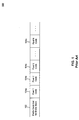
- FIG. 1 illustrates an exemplary entropy coding standard.
- FIG. 2 is a flowchart of a process illustrating steps by which to eliminate code block interdependencies, in accordance with an embodiment of the present disclosure.
- FIG. 3 is a flowchart of an encoding process illustrating steps by which a code block can be divided into pixel groups (sub-blocks), in accordance with an embodiment of the present disclosure.
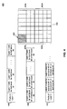
- FIG. 4 illustrates a manner of dividing a code block into blocks and sub-blocks, in accordance with an embodiment of the present disclosure.
- FIG. 5 is a flowchart of a process illustrating decoding steps, in accordance with an embodiment of the present disclosure.
- FIG. 6 depicts an example computer system in which embodiments of the present disclosure may be implemented.
- modules in this specification and the claims means any combination of hardware, firmware, or software components for performing the indicated function.
- a module need not be a rigidly defined entity, such that several modules may overlap hardware and software components in functionality.
- a software module may refer to a single line of code within a procedure, the procedure itself being a separate software module.
- One skilled in the relevant arts will understand that the functionality of modules may be defined in accordance with a number of stylistic or performance-optimizing techniques, for example.
- FIG. 1 illustrates an exemplary entropy coding standard 100.
- Entropy coding such as Huffman coding, is a lossless data compression technique that relies on a corresponding variable-length prefix-free codeword (or simply "code") to represent each fixed-length input.
- code a codeword
- a set of pixels 104a, 104b, 104c, 104n are provided in a data stream.
- Each pixel might be represented, for example, by 24-bits of data comprising color intensity information for that pixel (e.g., 8 bits of data for red, 8 bits of data for green, 8 bits of data for blue).
- these codes are determined using known coding techniques (such as Huffman coding).
- code lengths are variable. In the above example, after detecting a '1' at the beginning of a coding sequence, the color would be determined to be yellow - the next bit of data would be the start of a new code. The code '0' at the beginning of a coding sequence simply reduces the possibilities to 'red' or 'blue', depending on the next bit of data.
- This behavior is often included into data structures such as trees for ease of navigation.
- a code sequence such as "1001010111011” would translate to 'yellow' (1), 'red' (00), 'yellow' (1), 'blue' (01), 'blue' (01), 'yellow' (1), 'yellow' (1), 'blue' (01), 'yellow' (1).
- the codes themselves e.g., the data structure such as a tree
- each pixel 104 comprises only as many bits of data as is needed to uniquely represent its prefix code.
- a significant flaw of this approach is that the entire code sequence must necessarily be decoded serially. It is not possible to, for example, have a first processing thread decode the first X pixels, and a second processing thread decode the second Y pixels, because the divisions between pixels are unknown ahead of time. For example, jumping into the middle of the above example code sequence (e.g., '111011') and decoding it as per usual would produce 'yellow' (1) as the first value. However, that first '1' is, in reality, part of the '01' code for 'blue', but it is not possible to determine this without serially processing the entire sequence.
- the existing decoding technique must be handled serially.
- a previous pixel must be decoded in order to learn the information needed to decode a subsequent pixel. Accordingly, a technique is needed to eliminate this interdependency in order to achieve parallelism.
- FIG. 2 is a flowchart of a process 200 illustrating steps by which to eliminate code block interdependencies, in accordance with an embodiment of the present disclosure.
- code blocks e.g., a 16x16 pixel block
- FIG. 2 is a flowchart of a process 200 illustrating steps by which to eliminate code block interdependencies, in accordance with an embodiment of the present disclosure.
- code blocks e.g., a 16x16 pixel block
- code blocks are independent of other code blocks within a picture or sequence of pictures, although one skilled in the relevant arts would understand that the techniques described herein could be applied at any level (e.g., with interdependent code blocks within independent pictures, with interdependent pictures within independent streams, etc.).
- a code block (e.g., a picture divided into 16x16 code blocks) is divided into pixel groups. For example, a complete picture may be divided into individual 16x16 code blocks, which in turn are divided into 8x8 pixel groups, and an 8x8 pixel group may be divided into four 4x4 pixel groups.
- a determination is made as to whether to perform further division on the new pixel groups. If yes, the method proceeds to step 204 to further divide the pixel groups (e.g., each 4x4 pixel group may be further divided into four 2x2 pixel groups; four 4x1 pixel groups; a combination of one 2x1, one 2x3, and two 1x4 pixel groups; etc.).
- each 4x4 pixel group may be further divided into four 2x2 pixel groups; four 4x1 pixel groups; a combination of one 2x1, one 2x3, and two 1x4 pixel groups; etc.
- the divisions performed at step 204 can be handled by a same module or by several different modules, as appropriate
- step 208 If no further division is requested, the method then proceeds to step 208 where local prefix codes are provided at each layer. The method then ends at step 210.
- Each division is named according to a layer number, in accordance with an embodiment of the present invention.
- the code blocks at the first level of division of an overall picture comprise "layer 0".
- the first set of pixel groups e.g., the 8x8 pixel groups dividing a 16x16 code block
- layers 0-3 are utilized.
- each code block comprises a set of quantized coefficients used to express pixel values within that block.
- the code blocks can contain additional or different data, and the use of quantized coefficients is provided by way of example, and not limitation. Specifically, although coefficients are often quantized, they can be non-quantized. Accordingly, the disclosed embodiments are also contemplated to work with a set of non-quantized coefficients.
- Code blocks are divided in accordance to "cluster patterns" - such that a 4x4 pixel group can be divided, as discussed above, into four 2x2 pixel groups, four 4x1 pixel groups, a combination of one 2x1, one 2x3, and two 1x4 pixel groups, or other patterns such as triangular, diagonal, or L-shaped patterns, in accordance with an embodiment of the present disclosure.
- an encoder will signal to a decoder which pattern(s) have been chosen by, for example, embedding the cluster pattern information in the prefix of a block or sub-block, or the pattern should otherwise be known ahead of time by the decoder.
- FIG. 3 is a flowchart of an encoding process 300 illustrating steps by which a code block can be divided into pixel groups (sub-blocks), in accordance with an embodiment of the present disclosure.
- a code block can be divided into pixel groups (sub-blocks), in accordance with an embodiment of the present disclosure.
- sub-blocks pixel groups
- FIG. 3 is a flowchart of an encoding process 300 illustrating steps by which a code block can be divided into pixel groups (sub-blocks), in accordance with an embodiment of the present disclosure.
- a 4x4 code block can be divided into four 2x2 blocks - an implementation may always opt to perform this particular division, or may utilize cluster patterns as described in further detail blow.
- a code block comprises several pixel groups ultimately divided into 4x4 blocks (e.g., 16x16 code blocks divided into 8x8 pixel groups, each divided into 4x4 pixel groups).
- the 4x4 blocks are each divided into further sub-blocks, as described below.
- the method begins at step 302 and proceeds to step 304 where possible cluster patterns to be analyzed are determined. For example, if there is a choice between four 2x2 sub-blocks or four 4x1 sub-blocks, those are the two cluster patterns to be analyzed.
- step 304 possible cluster patterns to be analyzed are determined. For example, if there is a choice between four 2x2 sub-blocks or four 4x1 sub-blocks, those are the two cluster patterns to be analyzed.
- the patterns analyzed may comprise any subset of these patterns. Additionally, a particular pattern may be used without any analysis.
- minimum and maximum sizes for the sub-blocks are determined for a given cluster pattern. For example, with a cluster pattern of four 2x2 sub-blocks, the maximum code size to code each one of the sub-blocks is determined. Then, for the set of four 2x2 sub-blocks, the minimum code size (i.e., the code size for the individual sub-block with the smallest code size) is determined, along with the maximum code size (i.e., the code size of the individual sub-block with the largest code size).
- Determining the code size for each sub-block is accomplished by finding the two's complement size of each quantized coefficient, in accordance with an embodiment of the present disclosure, although one skilled in the relevant arts will appreciate that this technique can be applied differently to other data, or a different technique can be used to find the code size of all quantized coefficients.
- the maximum and minimum sizes of the sub-blocks can be determined based on the bits needed to represent the quantized coefficients by application of a particular code.
- the code is chosen by one skilled in coding techniques to encode individual quantized coefficients. This information is used, as described above, to determine minimum and maximum sizes of the corresponding cluster pattern (i.e., the minimum and maximum code size of the set of sub-blocks).
- a cluster pattern from a set of available cluster patterns is selected based on minimizing the total bits for the block (e.g., the 4x4 block) by adding all code sizes for encoding all quantized coefficients and the prefix code size for encoding the cluster pattern. For example, a determination can be made that using four 2x2 sub-blocks would require fewer bits to represent the entire block than using four 4x1 sub-blocks.
- prefix code information regarding the selected arrangement is stored as described below, and the method ends at step 312.
- 1 to 4 bits are needed to code the difference between the max size of the coefficients of the upper-left 4x4 block and the max size of the coefficients of each sub-block within that 4x4 block, while 1 or 3 bits may be needed to code the above difference for the rest of the 4x4 blocks.
- the algorithm can use 2 bits for the upper-left 4x4 block to specify the number of bits which would be used to code the number of bits used to code above difference, i.e.
- the size (number of bits that would be used to encode) of a cluster (such as a 4x4 block) is coded as part of prefix in the upper layer (such as the 8x8 block that contains the 4x4 block), so that when a decoder decodes the bit stream, it is able to extract all of the bits that are used to encode that cluster in parallel with extracting all of the bits that are used to encode other clusters.
- the layer below the cluster level e.g., the 4x4 block layer (layer 2) for the 2x2 sub-blocks (layer 3)
- layer 2 for the 2x2 sub-blocks (layer 3)
- layer 3 for the 2x2 sub-blocks
- an 8x8 code block 402 is shown divided into four 4x4 blocks, by way of non-limiting example consistent with an embodiment of the present disclosure.
- the four blocks, 404a, 404b, 404c, and 404d are each further divided into sub-blocks in accordance with a cluster or partition pattern, in accordance with an embodiment of the present disclosure.
- sub-block 405 is shown as a 2x2 block.
- all of the sub-blocks 405 of a block 404a are of a consistent size.
- it is compared to the maximum size of the other sub-blocks of block 404a to determine the maximum (and minimum) sizes of the sub-blocks.
- the difference between the max size of block 404a and the max size of each sub-block may require anywhere between 1 to 4 bits for coding. Therefore, 2 bits are dedicated to specify how many bits (from 1 to 4) are needed to code the above difference.
- a process to encode maximum size to that described in FIG. 3 is performed at the block level, where the max pattern size of each of the 4x4 blocks, i.e. 404a, 404b, 404c, 404d, is also encoded.
- FIG. 4 shows, on the left-hand side of the diagram, what is termed the Parallel Pyramid Entropy Coding ("PPEC") algorithm, in accordance with an embodiment of the present disclosure.
- PPEC Parallel Pyramid Entropy Coding
- each sub-block comprises encoded pixel data.
- Each block comprises data, as described above, with the bits that define the number of bits used in coding the difference between the max size of the block and the maximum size of each sub-block within the block, and the bits that codes the above difference, along with the bits that code the sub-block data.
- the overall code block data comprises the maximum size of each block, along with the prefix codes (e.g., Hoffman coding scheme) used to encode pixel data.
- prefix codes e.g., Hoffman coding scheme
- decoder size benefits greatly from the code blocks constructed in the aforementioned manner.
- a decoder operating on code blocks constructed in a manner consistent to the above description can process code blocks in parallel, and even individual sub-blocks can be processed in parallel.
- each symbol within a code block had to be decoded in sequence.
- multiple symbols e.g., pixel groups, character groups, or other groupings of decodable data
- the same processing speed can be obtained using a lower clock speed, resulting in energy efficiencies.
- a decoder is constructed in order to parse the information included by an encoder as discussed above to separate blocks and sub-blocks from the overall code block. This means, for example, that the decoder should be able to understand how many layers of division are present in the code block, what cluster patterns are utilized, etc. All of this data is specified somewhere in a header block or spread out throughout the code block.
- FIG. 5 is a flowchart of a process 500 illustrating decoding steps, in accordance with an embodiment of the present disclosure.
- the method begins at step 502 and proceeds to step 504 where block code data is separated into individual block components (e.g., blocks 404a, 404b, 404c, and 404d of FIG. 4 ).
- each block is further separated into sub-blocks (e.g., sub-block 405 of FIG. 4 ), in accordance with an embodiment of the present disclosure.
- the processing on each block at step 506 can be handled in parallel because the layer above (e.g., layer 1 for layer 2 decoding) defines the code size of the layer being decoded.
- decoding each sub-block at step 508 is handled in parallel because the size of each sub-block is defined and already decoded.
- the method ends at step 510.
- FIG. 6 illustrates an example computer system 600 in which the present disclosure, or portions thereof, can be implemented as computer-readable code.
- process 200 FIG. 2
- process 300 FIG. 3
- process 500 FIG. 5
- FIG. 6 illustrates an example computer system 600 in which the present disclosure, or portions thereof, can be implemented as computer-readable code.
- process 200 FIG. 2
- process 300 FIG. 3
- process 500 FIG. 5
- FIG. 6 illustrates an example computer system 600 in which the present disclosure, or portions thereof, can be implemented as computer-readable code.
- process 200 FIG. 2
- process 300 FIG. 3
- process 500 FIG. 5
- Computer system 600 includes one or more processors, such as processor 604.
- Processor 604 can be a special purpose or a general purpose processor.
- Processor 604 is connected to a communication infrastructure 606 (for example, a bus or network).
- Computer system 600 also includes a main memory 608, preferably random access memory (RAM), and may also include a secondary memory 610.
- Secondary memory 610 may include, for example, a hard disk drive 612, a removable storage drive 614, and/or a memory stick.
- Removable storage drive 614 may comprise a floppy disk drive, a magnetic tape drive, an optical disk drive, a flash memory, or the like.
- the removable storage drive 614 reads from and/or writes to a removable storage unit 615 in a well-known manner.
- Removable storage unit 615 may comprise a floppy disk, magnetic tape, optical disk, etc. that is read by and written to by removable storage drive 614.
- removable storage unit 615 includes a computer usable storage medium having stored therein computer software and/or data.
- secondary memory 610 may include other similar means for allowing computer programs or other instructions to be loaded into computer system 600.
- Such means may include, for example, a removable storage unit 622 and an interface 620.
- Examples of such means may include a program cartridge and cartridge interface (such as that found in video game devices), a removable memory chip (such as an EPROM, or PROM) and associated socket, and other removable storage units such as removable storage unit 622 and interfaces such as interface 620 that allow software and data to be transferred from the removable storage unit 622 to computer system 600.
- Computer system 600 may also include a communications interface 624.
- Communications interface 624 allows software and data to be transferred between computer system 600 and external devices.
- Communications interface 624 may include a modem, a network interface (such as an Ethernet card), a communications port, a PCMCIA slot and card, or the like.
- Software and data transferred via communications interface 624 are in the form of signals that may be electronic, electromagnetic, optical, or other signals capable of being received by communications interface 624. These signals are provided to communications interface 624 via a communications path 626.
- Communications path 626 carries signals and may be implemented using wire or cable, fiber optics, a phone line, a cellular phone link, an RF link or other communications channels.
- Computer program medium and “computer usable medium” are used to generally refer to media such as removable storage unit 615, removable storage unit 622, and a hard disk installed in hard disk drive 612. Signals carried over communications path 626 can also embody the logic described herein. Computer program medium and computer usable medium can also refer to memories, such as main memory 608 and secondary memory 610, which can be memory semiconductors (e.g. DRAMs, etc.). These computer program products are means for providing software to computer system 600.
- Computer programs are stored in main memory 608 and/or secondary memory 610. Computer programs may also be received via communications interface 624. Such computer programs, when executed, enable computer system 600 to implement the present disclosure as discussed herein. In particular, the computer programs, when executed, enable processor 604 to implement the processes of the present disclosure, such as the steps in process 200 ( FIG. 2 ), process 300 ( FIG. 3 ), and process 500 ( FIG. 5 ), discussed above. Accordingly, such computer programs represent controllers of the computer system 600. Where the disclosure is implemented using software, the software may be stored in a computer program product and loaded into computer system 600 using removable storage drive 614, interface 620, hard drive 612 or communications interface 624.
- the disclosure is also directed to computer program products comprising software stored on any computer useable medium.
- Such software when executed in one or more data processing device, causes a data processing device(s) to operate as described herein.
- Embodiments of the disclosure employ any computer useable or readable medium, known now or in the future.
- Examples of computer useable mediums include, but are not limited to, primary storage devices (e.g., any type of random access memory), secondary storage devices (e.g., hard drives, floppy disks, CD ROMS, ZIP disks, tapes, magnetic storage devices, optical storage devices, MEMS, nanotechnological storage device, etc.), and communication mediums (e.g., wired and wireless communications networks, local area networks, wide area networks, intranets, etc.).
Landscapes
- Engineering & Computer Science (AREA)
- Multimedia (AREA)
- Signal Processing (AREA)
- Compression Or Coding Systems Of Tv Signals (AREA)
- Compression, Expansion, Code Conversion, And Decoders (AREA)
Abstract
Description
- The present disclosure relates generally to video processing and, more particularly, to video coding techniques.
- Many processes in video coding involve processing of serial bit streams. These processes are themselves bound to serial operation in order to encode or decode the bit streams, requiring powerful processors to do so efficiently.
- In particular, when working with serial data, clock speed becomes a limiting factor. If each piece of data must be processed before the next piece of data can be resolved, system speed can be increased (often linearly) by increasing processing clock speed. However, high clock speeds require additional power consumption and heat dissipation.
- Accordingly, what is desired is a parallelizable coding technique.
- According to an aspect, a method comprises:
- dividing a code block into pixel groups;
- dividing the pixel groups into sub-blocks; and
- encoding pixels assigned to the sub-blocks using a layered encoding scheme for the code block.
- dividing the code block into four equal-sized pixel groups.
- determining a set of cluster patterns; and
- selecting a cluster pattern for arranging the corresponding sub-blocks of one of the pixel groups.
- determining minimum and maximum code sizes for each sub-block; and
- determining a minimum-size arrangement of the sub-blocks for the corresponding pixel group.
- storing code sizes for the sub-blocks and the pixel groups into an encoded stream using a layered entropy coding scheme.
- receiving a data stream comprising the code block;
- separating the code block into pixel groups using the code sizes and a layered decoding scheme;
- separating the pixel groups into sub-blocks using the code sizes; and
- decoding the sub-blocks in parallel.
- dividing a code block into pixel groups;
- dividing the pixel groups into sub-blocks; and
- encoding pixels assigned to the sub-blocks using a layered encoding scheme for the code block.
- dividing the code block into four equal-sized pixel groups.
- determining a set of cluster patterns; and
- selecting a cluster pattern for arranging the corresponding sub-blocks of one of the pixel groups.
- determining minimum and maximum code sizes for each sub-block; and
- determining a minimum-size arrangement of the sub-blocks for the corresponding pixel group.
- storing code sizes for the sub-blocks and the pixel groups into an encoded stream using a layered entropy coding scheme.
- receiving a data stream comprising the code block;
- separating the code block into pixel groups using the code sizes and a layered decoding scheme;
- separating the pixel groups into sub-blocks using the code sizes; and
- decoding the sub-blocks in parallel.
- an encoder stored in memory and configured to perform operations comprising:
- dividing a code block into pixel groups,
- dividing the pixel groups into sub-blocks, and
- encoding pixels assigned to the sub-blocks using a layered encoding scheme for the code block; and
- one or more processors configured to process the encoder.
- dividing the code block into four equal-sized pixel groups.
- determining a set of cluster patterns; and
- selecting a cluster pattern for arranging the corresponding sub-blocks of one of the pixel groups.
- determining minimum and maximum code sizes for each sub-block; and
- determining a minimum-size arrangement of the sub-blocks for the corresponding pixel group.
- storing code sizes for the sub-blocks and the pixel groups into an encoded stream using a layered entropy coding scheme.
- a decoder configured to perform operations comprising:
- receiving a data stream comprising the code block,
- separating the code block into pixel groups using the code sizes and a layered decoding scheme,
- separating the pixel groups into sub-blocks using the code sizes, and
- decoding the sub-blocks in parallel.
- The accompanying drawings, which are incorporated herein and form a part of the specification, illustrate embodiments of the present disclosure and, together with the description, further serve to explain the principles of the disclosure and to enable a person skilled in the relevant art to make and use disclosed embodiments.
-
FIG. 1 illustrates an exemplary entropy coding standard. -
FIG. 2 is a flowchart of a process illustrating steps by which to eliminate code block interdependencies, in accordance with an embodiment of the present disclosure. -
FIG. 3 is a flowchart of an encoding process illustrating steps by which a code block can be divided into pixel groups (sub-blocks), in accordance with an embodiment of the present disclosure. -
FIG. 4 illustrates a manner of dividing a code block into blocks and sub-blocks, in accordance with an embodiment of the present disclosure. -
FIG. 5 is a flowchart of a process illustrating decoding steps, in accordance with an embodiment of the present disclosure. -
FIG. 6 depicts an example computer system in which embodiments of the present disclosure may be implemented. - Embodiments of the disclosure will be described in detail with reference to the accompanying drawings. In the drawings, generally, like reference numbers indicate identical or functionally similar elements. Additionally, generally, the left-most digit(s) of a reference number identifies the drawing in which the reference number first appears.
- The following detailed description refers to the accompanying drawings that illustrate exemplary embodiments. Other embodiments are possible, and modifications can be made to the embodiments within the spirit and scope of the disclosure. Therefore, the detailed description is not meant to limit the invention. Rather, the scope of the invention is defined by the appended claims.
- It would be apparent to one of skill in the art that the disclosure can be implemented in many different embodiments of software, hardware, firmware, and/or the entities illustrated in the figures. Any actual software code with the specialized control of hardware to implement the present disclosure is not limiting of the present disclosure. Thus, the operational behavior of the present disclosure will be described with the understanding that modifications and variations of the embodiments are possible, and within the scope and spirit of the present disclosure.
- Reference to modules in this specification and the claims means any combination of hardware, firmware, or software components for performing the indicated function. A module need not be a rigidly defined entity, such that several modules may overlap hardware and software components in functionality. For example, a software module may refer to a single line of code within a procedure, the procedure itself being a separate software module. One skilled in the relevant arts will understand that the functionality of modules may be defined in accordance with a number of stylistic or performance-optimizing techniques, for example.
- According to disclosed embodiments there are provided methods, computer-readable storage devices, and systems for dividing a code block into pixel groups, dividing the pixel groups into sub-blocks, and encoding pixels assigned to the sub-blocks using an encoding scheme for the code block.
- Further features and advantages of the disclosure, as well as the structure and operation of various embodiments of the disclosure, are described in detail below with reference to the accompanying drawings. It is noted that the disclosure is not limited to the specific embodiments described herein. Such embodiments are presented herein for illustrative purposes only. Additional embodiments will be apparent to persons skilled in the relevant art(s) based on the teachings contained herein.
-
FIG. 1 illustrates an exemplaryentropy coding standard 100. Entropy coding, such as Huffman coding, is a lossless data compression technique that relies on a corresponding variable-length prefix-free codeword (or simply "code") to represent each fixed-length input. For example, as shown incoding standard 100, a set ofpixels - Assuming, for example, that all of the pixels within a 16x16 pixel block have a color selected from a palette of only three possible colors. In that case, entropy coding could represent the four possible values using only a maximum of two bits of data (e.g. '00' = red, '01' = blue, '1' = yellow). During a coding phase, these codes are determined using known coding techniques (such as Huffman coding). Note that in entropy coding, as would be understood by one skilled in the relevant art, code lengths are variable. In the above example, after detecting a '1' at the beginning of a coding sequence, the color would be determined to be yellow - the next bit of data would be the start of a new code. The code '0' at the beginning of a coding sequence simply reduces the possibilities to 'red' or 'blue', depending on the next bit of data.
- This behavior is often included into data structures such as trees for ease of navigation. By way of example, a code sequence such as "1001010111011" would translate to 'yellow' (1), 'red' (00), 'yellow' (1), 'blue' (01), 'blue' (01), 'yellow' (1), 'yellow' (1), 'blue' (01), 'yellow' (1). The codes themselves (e.g., the data structure such as a tree) can be provided together with the encoded data as a
prefix code list 102. Then, each pixel 104 comprises only as many bits of data as is needed to uniquely represent its prefix code. - A significant flaw of this approach is that the entire code sequence must necessarily be decoded serially. It is not possible to, for example, have a first processing thread decode the first X pixels, and a second processing thread decode the second Y pixels, because the divisions between pixels are unknown ahead of time. For example, jumping into the middle of the above example code sequence (e.g., '111011') and decoding it as per usual would produce 'yellow' (1) as the first value. However, that first '1' is, in reality, part of the '01' code for 'blue', but it is not possible to determine this without serially processing the entire sequence.
- As described above, the existing decoding technique must be handled serially. A previous pixel must be decoded in order to learn the information needed to decode a subsequent pixel. Accordingly, a technique is needed to eliminate this interdependency in order to achieve parallelism.
-
FIG. 2 is a flowchart of aprocess 200 illustrating steps by which to eliminate code block interdependencies, in accordance with an embodiment of the present disclosure. By way of example, and not limitation, code blocks (e.g., a 16x16 pixel block) are independent of other code blocks within a picture or sequence of pictures, although one skilled in the relevant arts would understand that the techniques described herein could be applied at any level (e.g., with interdependent code blocks within independent pictures, with interdependent pictures within independent streams, etc.). - The method begins at
step 202 and proceeds to step 204 where a code block (e.g., a picture divided into 16x16 code blocks) is divided into pixel groups. For example, a complete picture may be divided into individual 16x16 code blocks, which in turn are divided into 8x8 pixel groups, and an 8x8 pixel group may be divided into four 4x4 pixel groups. Atstep 206, a determination is made as to whether to perform further division on the new pixel groups. If yes, the method proceeds to step 204 to further divide the pixel groups (e.g., each 4x4 pixel group may be further divided into four 2x2 pixel groups; four 4x1 pixel groups; a combination of one 2x1, one 2x3, and two 1x4 pixel groups; etc.). One skilled in the relevant arts will appreciate that the divisions performed atstep 204 can be handled by a same module or by several different modules, as appropriate. - If no further division is requested, the method then proceeds to step 208 where local prefix codes are provided at each layer. The method then ends at
step 210. Each division is named according to a layer number, in accordance with an embodiment of the present invention. The code blocks at the first level of division of an overall picture comprise "layer 0". The first set of pixel groups (e.g., the 8x8 pixel groups dividing a 16x16 code block) comprise "layer 1", and so on. In the above example, layers 0-3 are utilized. - In accordance with an embodiment of the present disclosure, each code block comprises a set of quantized coefficients used to express pixel values within that block. One skilled in the relevant arts will appreciate that the code blocks can contain additional or different data, and the use of quantized coefficients is provided by way of example, and not limitation. Specifically, although coefficients are often quantized, they can be non-quantized. Accordingly, the disclosed embodiments are also contemplated to work with a set of non-quantized coefficients.
- Code blocks are divided in accordance to "cluster patterns" - such that a 4x4 pixel group can be divided, as discussed above, into four 2x2 pixel groups, four 4x1 pixel groups, a combination of one 2x1, one 2x3, and two 1x4 pixel groups, or other patterns such as triangular, diagonal, or L-shaped patterns, in accordance with an embodiment of the present disclosure. Whatever pattern is used, an encoder will signal to a decoder which pattern(s) have been chosen by, for example, embedding the cluster pattern information in the prefix of a block or sub-block, or the pattern should otherwise be known ahead of time by the decoder.
-
FIG. 3 is a flowchart of anencoding process 300 illustrating steps by which a code block can be divided into pixel groups (sub-blocks), in accordance with an embodiment of the present disclosure. One skilled in the relevant arts will appreciate that various techniques can be applied at varying levels to segment blocks, and the techniques described herein are provided by way of example, and not limitation. For example, a 4x4 code block can be divided into four 2x2 blocks - an implementation may always opt to perform this particular division, or may utilize cluster patterns as described in further detail blow. - For the purposes of the examples outlined herein, a code block comprises several pixel groups ultimately divided into 4x4 blocks (e.g., 16x16 code blocks divided into 8x8 pixel groups, each divided into 4x4 pixel groups). The 4x4 blocks are each divided into further sub-blocks, as described below.
- The method begins at
step 302 and proceeds to step 304 where possible cluster patterns to be analyzed are determined. For example, if there is a choice between four 2x2 sub-blocks or four 4x1 sub-blocks, those are the two cluster patterns to be analyzed. One skilled in the relevant arts will appreciate that a number of cluster patterns may be available, and the patterns analyzed may comprise any subset of these patterns. Additionally, a particular pattern may be used without any analysis. - At
step 306, minimum and maximum sizes for the sub-blocks are determined for a given cluster pattern. For example, with a cluster pattern of four 2x2 sub-blocks, the maximum code size to code each one of the sub-blocks is determined. Then, for the set of four 2x2 sub-blocks, the minimum code size (i.e., the code size for the individual sub-block with the smallest code size) is determined, along with the maximum code size (i.e., the code size of the individual sub-block with the largest code size). - Determining the code size for each sub-block is accomplished by finding the two's complement size of each quantized coefficient, in accordance with an embodiment of the present disclosure, although one skilled in the relevant arts will appreciate that this technique can be applied differently to other data, or a different technique can be used to find the code size of all quantized coefficients. The maximum and minimum sizes of the sub-blocks can be determined based on the bits needed to represent the quantized coefficients by application of a particular code. In accordance with an embodiment of the present invention, the code is chosen by one skilled in coding techniques to encode individual quantized coefficients. This information is used, as described above, to determine minimum and maximum sizes of the corresponding cluster pattern (i.e., the minimum and maximum code size of the set of sub-blocks).
- The sizes of the various cluster patterns are compared with other cluster patterns in
step 308. In accordance with an embodiment of the present disclosure, a cluster pattern from a set of available cluster patterns is selected based on minimizing the total bits for the block (e.g., the 4x4 block) by adding all code sizes for encoding all quantized coefficients and the prefix code size for encoding the cluster pattern. For example, a determination can be made that using four 2x2 sub-blocks would require fewer bits to represent the entire block than using four 4x1 sub-blocks. - At
step 310, prefix code information regarding the selected arrangement is stored as described below, and the method ends atstep 312. By way of non-limiting example, 1 to 4 bits are needed to code the difference between the max size of the coefficients of the upper-left 4x4 block and the max size of the coefficients of each sub-block within that 4x4 block, while 1 or 3 bits may be needed to code the above difference for the rest of the 4x4 blocks. The algorithm can use 2 bits for the upper-left 4x4 block to specify the number of bits which would be used to code the number of bits used to code above difference, i.e. the difference between the max size of the coefficients of the upper-left 4x4 block and the max size of the coefficients of each sub-block of the pattern within that 4x4 block, and 1 bit for the rest of the of the 4x4 blocks to specify the number of bits which would be used to code the number of bits used to code above difference, i.e. either 1 or 3 bits to be used to code the above difference of the rest of the 4x4 blocks. - In accordance with an embodiment of the present disclosure, the size (number of bits that would be used to encode) of a cluster (such as a 4x4 block) is coded as part of prefix in the upper layer (such as the 8x8 block that contains the 4x4 block), so that when a decoder decodes the bit stream, it is able to extract all of the bits that are used to encode that cluster in parallel with extracting all of the bits that are used to encode other clusters. The same idea is applied to the layer below the cluster level (e.g., the 4x4 block layer (layer 2) for the 2x2 sub-blocks (layer 3)) in the above example, such as four 2x2 sub-blocks that are composed of the cluster 4x4 block, where the number of bits that would be used to code each sub-block is coded as part of prefix in the 4x4 block.
- Turning to
FIG. 4 , an8x8 code block 402 is shown divided into four 4x4 blocks, by way of non-limiting example consistent with an embodiment of the present disclosure. The four blocks, 404a, 404b, 404c, and 404d are each further divided into sub-blocks in accordance with a cluster or partition pattern, in accordance with an embodiment of the present disclosure. - In the case of
block 404a, sub-block 405 is shown as a 2x2 block. In accordance with an embodiment of the present disclosure, all of thesub-blocks 405 of ablock 404a are of a consistent size. After determining a maximum size ofsub-block 405, as discussed above, it is compared to the maximum size of the other sub-blocks ofblock 404a to determine the maximum (and minimum) sizes of the sub-blocks. Consistent with the above example, the difference between the max size ofblock 404a and the max size of each sub-block may require anywhere between 1 to 4 bits for coding. Therefore, 2 bits are dedicated to specify how many bits (from 1 to 4) are needed to code the above difference. - A process to encode maximum size to that described in
FIG. 3 is performed at the block level, where the max pattern size of each of the 4x4 blocks, i.e. 404a, 404b, 404c, 404d, is also encoded. -
FIG. 4 shows, on the left-hand side of the diagram, what is termed the Parallel Pyramid Entropy Coding ("PPEC") algorithm, in accordance with an embodiment of the present disclosure. The name is from the notion that this diagram, were it to be expanded, would appear like a pyramid, with the encodedpixel data 410 as the base,sub-block data 408 as a middle layer, and blockdata 406 as a top layer. In each layer, all blocks or sub-blocks can be encoded and decoded in parallel. - As shown in
FIG. 4 , each sub-block comprises encoded pixel data. Each block comprises data, as described above, with the bits that define the number of bits used in coding the difference between the max size of the block and the maximum size of each sub-block within the block, and the bits that codes the above difference, along with the bits that code the sub-block data. The overall code block data comprises the maximum size of each block, along with the prefix codes (e.g., Hoffman coding scheme) used to encode pixel data. One skilled in the relevant arts will appreciate that while this diagram illustrates the various components discussed above, the components do not need to appear in the particular order shown inFIG. 4 . Additionally, as previously discussed, additional layers can be introduced to provide finer divisions of sub-blocks and sub-sub-blocks. Moreover, a hybrid approach can be utilized where certain blocks are divided into sub-blocks, but other blocks are serially encoded without further division. One skilled in the relevant arts will appreciate that such variations and others are within the scope and spirit of this disclosure. - The decoder size benefits greatly from the code blocks constructed in the aforementioned manner. In accordance with an embodiment of the present disclosure, a decoder operating on code blocks constructed in a manner consistent to the above description can process code blocks in parallel, and even individual sub-blocks can be processed in parallel.
- In prior serial operation, each symbol within a code block had to be decoded in sequence. However, by breaking down the code block into layers as described herein, multiple symbols (e.g., pixel groups, character groups, or other groupings of decodable data) can be decoded in parallel, providing an improvement of an order of magnitude over serial processing solutions running at a comparable clock speed. Alternatively, the same processing speed can be obtained using a lower clock speed, resulting in energy efficiencies.
- A decoder is constructed in order to parse the information included by an encoder as discussed above to separate blocks and sub-blocks from the overall code block. This means, for example, that the decoder should be able to understand how many layers of division are present in the code block, what cluster patterns are utilized, etc. All of this data is specified somewhere in a header block or spread out throughout the code block.
-
FIG. 5 is a flowchart of a process 500 illustrating decoding steps, in accordance with an embodiment of the present disclosure. The method begins atstep 502 and proceeds to step 504 where block code data is separated into individual block components (e.g.,blocks FIG. 4 ). Atstep 506, each block is further separated into sub-blocks (e.g., sub-block 405 ofFIG. 4 ), in accordance with an embodiment of the present disclosure. Notably, the processing on each block atstep 506 can be handled in parallel because the layer above (e.g.,layer 1 forlayer 2 decoding) defines the code size of the layer being decoded. Moreover, decoding each sub-block atstep 508 is handled in parallel because the size of each sub-block is defined and already decoded. The method ends atstep 510. - Various aspects of the present disclosure can be implemented by software, firmware, hardware, or a combination thereof.
FIG. 6 illustrates anexample computer system 600 in which the present disclosure, or portions thereof, can be implemented as computer-readable code. For example, process 200 (FIG. 2 ), process 300 (FIG. 3 ), and process 500 (FIG. 5 ) can be implemented insystem 600. Various embodiments of the disclosure are described in terms of thisexample computer system 600. After reading this description, it will become apparent to a person skilled in the relevant art how to implement the disclosure using other computer systems and/or computer architectures. -
Computer system 600 includes one or more processors, such asprocessor 604.Processor 604 can be a special purpose or a general purpose processor.Processor 604 is connected to a communication infrastructure 606 (for example, a bus or network). -
Computer system 600 also includes amain memory 608, preferably random access memory (RAM), and may also include asecondary memory 610.Secondary memory 610 may include, for example, ahard disk drive 612, aremovable storage drive 614, and/or a memory stick.Removable storage drive 614 may comprise a floppy disk drive, a magnetic tape drive, an optical disk drive, a flash memory, or the like. Theremovable storage drive 614 reads from and/or writes to aremovable storage unit 615 in a well-known manner.Removable storage unit 615 may comprise a floppy disk, magnetic tape, optical disk, etc. that is read by and written to byremovable storage drive 614. As will be appreciated by persons skilled in the relevant art(s),removable storage unit 615 includes a computer usable storage medium having stored therein computer software and/or data. - In alternative implementations,
secondary memory 610 may include other similar means for allowing computer programs or other instructions to be loaded intocomputer system 600. Such means may include, for example, aremovable storage unit 622 and aninterface 620. Examples of such means may include a program cartridge and cartridge interface (such as that found in video game devices), a removable memory chip (such as an EPROM, or PROM) and associated socket, and other removable storage units such asremovable storage unit 622 and interfaces such asinterface 620 that allow software and data to be transferred from theremovable storage unit 622 tocomputer system 600. -
Computer system 600 may also include a communications interface 624. Communications interface 624 allows software and data to be transferred betweencomputer system 600 and external devices. Communications interface 624 may include a modem, a network interface (such as an Ethernet card), a communications port, a PCMCIA slot and card, or the like. Software and data transferred via communications interface 624 are in the form of signals that may be electronic, electromagnetic, optical, or other signals capable of being received by communications interface 624. These signals are provided to communications interface 624 via acommunications path 626.Communications path 626 carries signals and may be implemented using wire or cable, fiber optics, a phone line, a cellular phone link, an RF link or other communications channels. - In this document, the terms "computer program medium" and "computer usable medium" are used to generally refer to media such as
removable storage unit 615,removable storage unit 622, and a hard disk installed inhard disk drive 612. Signals carried overcommunications path 626 can also embody the logic described herein. Computer program medium and computer usable medium can also refer to memories, such asmain memory 608 andsecondary memory 610, which can be memory semiconductors (e.g. DRAMs, etc.). These computer program products are means for providing software tocomputer system 600. - Computer programs (also called computer control logic) are stored in
main memory 608 and/orsecondary memory 610. Computer programs may also be received via communications interface 624. Such computer programs, when executed, enablecomputer system 600 to implement the present disclosure as discussed herein. In particular, the computer programs, when executed, enableprocessor 604 to implement the processes of the present disclosure, such as the steps in process 200 (FIG. 2 ), process 300 (FIG. 3 ), and process 500 (FIG. 5 ), discussed above. Accordingly, such computer programs represent controllers of thecomputer system 600. Where the disclosure is implemented using software, the software may be stored in a computer program product and loaded intocomputer system 600 usingremovable storage drive 614,interface 620,hard drive 612 or communications interface 624. - The disclosure is also directed to computer program products comprising software stored on any computer useable medium. Such software, when executed in one or more data processing device, causes a data processing device(s) to operate as described herein. Embodiments of the disclosure employ any computer useable or readable medium, known now or in the future. Examples of computer useable mediums include, but are not limited to, primary storage devices (e.g., any type of random access memory), secondary storage devices (e.g., hard drives, floppy disks, CD ROMS, ZIP disks, tapes, magnetic storage devices, optical storage devices, MEMS, nanotechnological storage device, etc.), and communication mediums (e.g., wired and wireless communications networks, local area networks, wide area networks, intranets, etc.).
- It is to be appreciated that the Detailed Description section, and not the Summary and Abstract sections, is intended to be used to interpret the claims. The Summary and Abstract sections may set forth one or more but not all exemplary embodiments of the present disclosure as contemplated by the inventor(s), and thus, are not intended to limit the present disclosure and the appended claims in any way.
- The present disclosure has been described above with the aid of functional building blocks illustrating the implementation of specified functions and relationships thereof. The boundaries of these functional building blocks have been arbitrarily defined herein for the convenience of the description. Alternate boundaries can be defined so long as the specified functions and relationships thereof are appropriately performed.
- The foregoing description of the specific embodiments will so fully reveal the general nature of the disclosure that others can, by applying knowledge within the skill of the art, readily modify and/or adapt for various applications such specific embodiments, without undue experimentation, without departing from the general concept of the present disclosure. Therefore, such adaptations and modifications are intended to be within the meaning and range of equivalents of the disclosed embodiments, based on the teaching and guidance presented herein. It is to be understood that the phraseology or terminology herein is for the purpose of description and not of limitation, such that the terminology or phraseology of the present specification is to be interpreted by the skilled artisan in light of the teachings and guidance.
- The breadth and scope of the present disclosure should not be limited by any of the above-described exemplary embodiments, but should be defined only in accordance with the following claims and their equivalents.
Claims (15)
- A method comprising:dividing a code block into pixel groups;dividing the pixel groups into sub-blocks; andencoding pixels assigned to the sub-blocks using a layered encoding scheme for the code block.
- The method of claim 1, wherein dividing the code block into pixel groups comprises:dividing the code block into four equal-sized pixel groups.
- The method of claim 1, wherein dividing the pixel groups into sub-groups comprises:determining a set of cluster patterns; andselecting a cluster pattern for arranging the corresponding sub-blocks of one of the pixel groups.
- The method of claim 3, wherein selecting the cluster pattern comprises:determining minimum and maximum code sizes for each sub-block; anddetermining a minimum-size arrangement of the sub-blocks for the corresponding pixel group.
- The method of claim 1, further comprising:storing code sizes for the sub-blocks and the pixel groups into an encoded stream using a layered entropy coding scheme.
- The method of claim 5, further comprising:receiving a data stream comprising the code block;separating the code block into pixel groups using the code sizes and a layered decoding scheme;separating the pixel groups into sub-blocks using the code sizes; anddecoding the sub-blocks in parallel.
- A computer-readable storage device having instructions stored thereon, execution of which, by a computing device, causes the computing device to perform operations comprising:dividing a code block into pixel groups;dividing the pixel groups into sub-blocks; andencoding pixels assigned to the sub-blocks using a layered encoding scheme for the code block.
- The computer-readable storage device of claim 7, wherein dividing the code block into pixel groups comprises:dividing the code block into four equal-sized pixel groups.
- The computer-readable storage device of claim 7, wherein dividing the pixel groups into sub-groups comprises:determining a set of cluster patterns; andselecting a cluster pattern for arranging the corresponding sub-blocks of one of the pixel groups.
- A system comprising:an encoder stored in memory and configured to perform operations comprising:dividing a code block into pixel groups,dividing the pixel groups into sub-blocks, andencoding pixels assigned to the sub-blocks using a layered encoding scheme for the code block; andone or more processors configured to process the encoder.
- The system of claim 10, wherein dividing the code block into pixel groups comprises:dividing the code block into four equal-sized pixel groups.
- The system of claim 10, wherein dividing the pixel groups into sub-groups comprises:determining a set of cluster patterns; andselecting a cluster pattern for arranging the corresponding sub-blocks of one of the pixel groups.
- The system of claim 12, wherein selecting the cluster pattern comprises:determining minimum and maximum code sizes for each sub-block; anddetermining a minimum-size arrangement of the sub-blocks for the corresponding pixel group.
- The system of claim 10, wherein the encoder is further configured to perform operations comprising:storing code sizes for the sub-blocks and the pixel groups into an encoded stream using a layered entropy coding scheme.
- The system of claim 14, further comprising:a decoder configured to perform operations comprising:receiving a data stream comprising the code block,separating the code block into pixel groups using the code sizes and a layered decoding scheme,separating the pixel groups into sub-blocks using the code sizes, anddecoding the sub-blocks in parallel.
Applications Claiming Priority (1)
| Application Number | Priority Date | Filing Date | Title |
|---|---|---|---|
| US13/408,404 US9106932B2 (en) | 2012-02-29 | 2012-02-29 | Parallel pyramid entropy coding for video and image compression |
Publications (2)
| Publication Number | Publication Date |
|---|---|
| EP2635026A2 true EP2635026A2 (en) | 2013-09-04 |
| EP2635026A3 EP2635026A3 (en) | 2015-12-16 |
Family
ID=47630050
Family Applications (1)
| Application Number | Title | Priority Date | Filing Date |
|---|---|---|---|
| EP12008624.4A Ceased EP2635026A3 (en) | 2012-02-29 | 2012-12-27 | Parallel pyramid entropy coding for video and image compression |
Country Status (5)
| Country | Link |
|---|---|
| US (1) | US9106932B2 (en) |
| EP (1) | EP2635026A3 (en) |
| KR (1) | KR101443804B1 (en) |
| CN (1) | CN103297768B (en) |
| TW (1) | TWI517662B (en) |
Families Citing this family (6)
| Publication number | Priority date | Publication date | Assignee | Title |
|---|---|---|---|---|
| JP2013055500A (en) * | 2011-09-02 | 2013-03-21 | Sony Corp | Solid state imaging device and camera system |
| CN103596011B (en) * | 2013-11-20 | 2017-07-04 | 北京中星微电子有限公司 | The storage processing method and device of view data |
| US8955027B1 (en) * | 2013-11-21 | 2015-02-10 | Google Inc. | Transcoding media streams using subchunking |
| JP6511284B2 (en) * | 2015-02-13 | 2019-05-15 | パナソニック株式会社 | Minimum value selection circuit, decoder and minimum value selection method |
| US11190975B2 (en) * | 2017-02-13 | 2021-11-30 | Qualcomm Incorporated | Feedback techniques for wireless communications |
| CN112866723B (en) * | 2019-11-28 | 2024-04-19 | 瑞昱半导体股份有限公司 | Image data processing method and system |
Citations (2)
| Publication number | Priority date | Publication date | Assignee | Title |
|---|---|---|---|---|
| WO2010039728A2 (en) * | 2008-10-03 | 2010-04-08 | Qualcomm Incorporated | Video coding with large macroblocks |
| US20110150351A1 (en) * | 2009-12-21 | 2011-06-23 | Stmicroelectronics Pvt. Ltd. | Parallelization of variable length decoding |
Family Cites Families (6)
| Publication number | Priority date | Publication date | Assignee | Title |
|---|---|---|---|---|
| JP3679083B2 (en) * | 2002-10-08 | 2005-08-03 | 株式会社エヌ・ティ・ティ・ドコモ | Image encoding method, image decoding method, image encoding device, image decoding device, image encoding program, image decoding program |
| US8718140B1 (en) * | 2005-05-12 | 2014-05-06 | Visualon, Inc. | Encoding video data |
| US8634456B2 (en) * | 2008-10-03 | 2014-01-21 | Qualcomm Incorporated | Video coding with large macroblocks |
| KR101038531B1 (en) * | 2009-06-25 | 2011-06-02 | 한양대학교 산학협력단 | Image coding apparatus and method capable of parallel processing at decoding, and Image decoding apparatus and method capable of parallel processing |
| JP2011091575A (en) * | 2009-10-21 | 2011-05-06 | Sony Corp | Coding apparatus and method |
| US8848779B2 (en) * | 2010-07-15 | 2014-09-30 | Sharp Laboratories Of America, Inc. | Method of parallel video coding based on block size |
-
2012
- 2012-02-29 US US13/408,404 patent/US9106932B2/en not_active Expired - Fee Related
- 2012-12-12 TW TW101146843A patent/TWI517662B/en not_active IP Right Cessation
- 2012-12-26 CN CN201210576656.9A patent/CN103297768B/en active Active
- 2012-12-27 EP EP12008624.4A patent/EP2635026A3/en not_active Ceased
-
2013
- 2013-02-27 KR KR1020130020984A patent/KR101443804B1/en not_active Expired - Fee Related
Patent Citations (2)
| Publication number | Priority date | Publication date | Assignee | Title |
|---|---|---|---|---|
| WO2010039728A2 (en) * | 2008-10-03 | 2010-04-08 | Qualcomm Incorporated | Video coding with large macroblocks |
| US20110150351A1 (en) * | 2009-12-21 | 2011-06-23 | Stmicroelectronics Pvt. Ltd. | Parallelization of variable length decoding |
Also Published As
| Publication number | Publication date |
|---|---|
| CN103297768B (en) | 2017-12-29 |
| TWI517662B (en) | 2016-01-11 |
| EP2635026A3 (en) | 2015-12-16 |
| TW201336311A (en) | 2013-09-01 |
| KR20130099863A (en) | 2013-09-06 |
| US9106932B2 (en) | 2015-08-11 |
| CN103297768A (en) | 2013-09-11 |
| KR101443804B1 (en) | 2014-11-04 |
| US20130223536A1 (en) | 2013-08-29 |
Similar Documents
| Publication | Publication Date | Title |
|---|---|---|
| US9106932B2 (en) | Parallel pyramid entropy coding for video and image compression | |
| RU2674332C2 (en) | Method of video coding with the use of a separate coding tree for brightness and color | |
| RU2636680C1 (en) | Method and device for coding or decoding | |
| CN101803388B (en) | Image decoding device, image decoding method, image encoding device, and image encoding method | |
| CN102939719B (en) | For the method and apparatus reducing source in binary system entropy code and decoding | |
| CN104754362B (en) | Image compression method using finely divided block matching | |
| US10771792B2 (en) | Encoding data arrays | |
| WO2015120818A1 (en) | Picture coding and decoding methods and devices | |
| TWI539793B (en) | Decoder and method for decoding run-length-encoded data | |
| RU2014145559A (en) | SMALL DELAY ENCODING | |
| US10455244B2 (en) | Method and device for entropy encoding or entropy decoding video signal for high-capacity parallel processing | |
| RU2014145203A (en) | Grouping Syntaxis Elements with Encoding in Bypass Mode in Video Encoding | |
| CN102783035A (en) | Parallel entropy coding and decoding methods and devices | |
| WO2013141665A1 (en) | Video encoding method, video decoding method and apparatus using same | |
| JP2004134896A5 (en) | ||
| US20110058613A1 (en) | Method and apparatus for generating bitstream based on syntax element | |
| US7365659B1 (en) | Method of context adaptive binary arithmetic coding and coding apparatus using the same | |
| CN114827611B (en) | Video image encoding and decoding method, apparatus and medium | |
| CN111131826B (en) | Data compression method and device for fixed-length code unit containing multiple encoding parameter variable-length codes | |
| CN107431827A (en) | Method and apparatus for index map coding in video and image compression | |
| CN110291792B (en) | Asymmetric coding unit size depends on the block ratio | |
| CN115250351A (en) | Compression method, decompression method and related products for image data | |
| HK1185486A (en) | Parallel pyramid entropy coding for video and image compression | |
| JP5105191B2 (en) | Image processing device | |
| US20130188885A1 (en) | Apparatus and method for coding image, and non-transitory computer readable medium thereof |
Legal Events
| Date | Code | Title | Description |
|---|---|---|---|
| PUAI | Public reference made under article 153(3) epc to a published international application that has entered the european phase |
Free format text: ORIGINAL CODE: 0009012 |
|
| 17P | Request for examination filed |
Effective date: 20130102 |
|
| AK | Designated contracting states |
Kind code of ref document: A2 Designated state(s): AL AT BE BG CH CY CZ DE DK EE ES FI FR GB GR HR HU IE IS IT LI LT LU LV MC MK MT NL NO PL PT RO RS SE SI SK SM TR |
|
| AX | Request for extension of the european patent |
Extension state: BA ME |
|
| PUAL | Search report despatched |
Free format text: ORIGINAL CODE: 0009013 |
|
| AK | Designated contracting states |
Kind code of ref document: A3 Designated state(s): AL AT BE BG CH CY CZ DE DK EE ES FI FR GB GR HR HU IE IS IT LI LT LU LV MC MK MT NL NO PL PT RO RS SE SI SK SM TR |
|
| AX | Request for extension of the european patent |
Extension state: BA ME |
|
| RIC1 | Information provided on ipc code assigned before grant |
Ipc: H04N 7/26 00000000AFI20151112BHEP |
|
| 17Q | First examination report despatched |
Effective date: 20151214 |
|
| RBV | Designated contracting states (corrected) |
Designated state(s): AL AT BE BG CH CY CZ DE DK EE ES FI FR GB GR HR HU IE IS IT LI LT LU LV MC MK MT NL NO PL PT RO RS SE SI SK SM TR |
|
| RAP1 | Party data changed (applicant data changed or rights of an application transferred) |
Owner name: AVAGO TECHNOLOGIES GENERAL IP (SINGAPORE) PTE. LTD |
|
| RAP1 | Party data changed (applicant data changed or rights of an application transferred) |
Owner name: AVAGO TECHNOLOGIES INTERNATIONAL SALES PTE. LIMITE |
|
| STAA | Information on the status of an ep patent application or granted ep patent |
Free format text: STATUS: EXAMINATION IS IN PROGRESS |
|
| STAA | Information on the status of an ep patent application or granted ep patent |
Free format text: STATUS: THE APPLICATION HAS BEEN REFUSED |
|
| 18R | Application refused |
Effective date: 20240516 |