EP2634881A1 - Connector drip-proof member and cable structure - Google Patents
Connector drip-proof member and cable structure Download PDFInfo
- Publication number
- EP2634881A1 EP2634881A1 EP11836124.5A EP11836124A EP2634881A1 EP 2634881 A1 EP2634881 A1 EP 2634881A1 EP 11836124 A EP11836124 A EP 11836124A EP 2634881 A1 EP2634881 A1 EP 2634881A1
- Authority
- EP
- European Patent Office
- Prior art keywords
- cable
- connector
- drip
- proof member
- drainer
- Prior art date
- Legal status (The legal status is an assumption and is not a legal conclusion. Google has not performed a legal analysis and makes no representation as to the accuracy of the status listed.)
- Granted
Links
Images





Classifications
-
- H—ELECTRICITY
- H01—ELECTRIC ELEMENTS
- H01R—ELECTRICALLY-CONDUCTIVE CONNECTIONS; STRUCTURAL ASSOCIATIONS OF A PLURALITY OF MUTUALLY-INSULATED ELECTRICAL CONNECTING ELEMENTS; COUPLING DEVICES; CURRENT COLLECTORS
- H01R13/00—Details of coupling devices of the kinds covered by groups H01R12/70 or H01R24/00 - H01R33/00
- H01R13/46—Bases; Cases
- H01R13/52—Dustproof, splashproof, drip-proof, waterproof, or flameproof cases
- H01R13/5219—Sealing means between coupling parts, e.g. interfacial seal
- H01R13/5221—Sealing means between coupling parts, e.g. interfacial seal having cable sealing means
-
- H—ELECTRICITY
- H01—ELECTRIC ELEMENTS
- H01R—ELECTRICALLY-CONDUCTIVE CONNECTIONS; STRUCTURAL ASSOCIATIONS OF A PLURALITY OF MUTUALLY-INSULATED ELECTRICAL CONNECTING ELEMENTS; COUPLING DEVICES; CURRENT COLLECTORS
- H01R13/00—Details of coupling devices of the kinds covered by groups H01R12/70 or H01R24/00 - H01R33/00
- H01R13/46—Bases; Cases
- H01R13/52—Dustproof, splashproof, drip-proof, waterproof, or flameproof cases
Definitions
- This present invention relates to a connector drip-proof member and a cable structure.
- the cable structure contains a cable and a connector connected to an end of the cable.
- a water drop is generated on the cable by condensation. When the water drop runs down the cable to enter into the connector, electric connection may be disturbed. So, a water-proof means is provided in the cable structure.
- a drip loop can be listed.
- Figs. 1A and 1B show examples of the cable structure in which the drip loop is provided, respectively.
- a cable structure 100 shown in Fig. 1A has a cable 101 and a connector 102 attached to one end of the cable 101. The cable 101 is bent at the vicinity of the connector 102, and a drip loop 103 is formed thereby.
- the cable structure 100 shown in Fig. 1B has the cable 101 and the connector 102.
- the connector 102 is arranged to be downward.
- the cable 101 is bent at the vicinity of the connector to be convex upward, and the drip loop 103 is formed thereby. Since the drip loop 103 is formed, the water drop on the cable 101 is prevented from reaching the connector 102.
- potting can be listed.
- Fig. 2 is a schematic view showing the other example of the cable structure.
- a potting portion 104 is provided to cover a connection portion between the cable 101 and the connector 102.
- the potting portion 104 prevents liquid droplets on the cable 101 from entering into the connector 102.
- the patent literature 1 discloses a water-proof code connector that is provided with: a connector body having a plurality of blade and an outer cap fitting with the connector body.
- This water-proof code connector has an insertion cylinder having an opening through which an electric wire code is inserted, in the outer shell cap.
- a plurality of water-proof valve are circumferentially arranged at many stages for protecting the water entering into the outer shell cap.
- One water-proof valve is arranged on the opening side via a winding groove placed on the inner wall of the insertion cylinder.
- the plurality of water-proof valves are arranged on the inward side of the outer shell cap via the winding groove on the inner wall of the insertion cylinder.
- Patent literature 1 Japanese Unexamined Utility Model (Registration) Application Publication No. H06-44045 U
- the drip loop 103 when the drip loop 103 is arranged as shown in Fig 1A and 1B , the cable 101 becomes longer than necessary. Moreover, depending on the location in which the cable structure is arranged, a space for the drip loop 103 may not be obtained.
- the potting portion 104 when used as shown in Fig.2 , the potting portion should be cured after being applied. In order to form potting portion 104, much time is spent. Additionally, when detaching the connecter 102 from the cable101, the potting portion 102 should be removed and extra work is needed.
- the outer shell cap having water-proof valves, the winding groove or the like should be manufactured.
- the outer shell having a complicated structure is needed, and that brings disadvantages in a cost of manufacturing connectors.
- an object of the present invention is to provide a connector drip-proof member and cable structure, which can be applied to a narrow space, reduce workload for attaching, and be manufactured at low cost.
- a connector drip-proof member includes a cylinder part configured to be attached to a cable whose end is connected to a connector so as to cover a part of the cable, and a barb portion linked to the cylinder part and configured to prevent droplets on the cable from reaching the connector.
- the barb portion includes an upper surface configured to face to a back end side of the cable, and an under surface configured to face to an end side of the cable.
- the cylinder part penetrates the barb portion from the upper surface to the under surface.
- the upper surface is concave.
- the barb portion is provided, droplets are prevented from running down cable to reach the connector. Drip loops are not needed, and the connector drip-proof member can be attached to the cable even in a narrow space. Furthermore, since a potting material or the like is not needed, time is not spent in curing the potting material. Additionally, since a special structure is not necessary for the cable and the connector, waterproof processes can be conducted at low cost.
- a cable structure according to the present invention includes above mentioned drip-proof member, a cable to which the connector drip-proof member is attached, and a connector connected to an end of the cable.
- a connecter drip-proof member and cable structure which can be applied to a narrow space, reduce workload for attaching, and be manufactured at low cost.
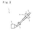
- Fig. 3 is a schematic view showing a cable structure 1 pertaining to the present embodiment.
- This cable structure 1 is assumed to be used to connect electronic equipments arranged in an airplane. There is a case that the attitude of the airplane changes during flight. For this reason, liquid droplets on a cable easily run down the cable. For this reason, a waterproof process against the liquid droplets running down the cable is requested. Also, a space in which the cable structure 1 can be arranged is limited. Thus, a waterproof process with small-footprint is required.
- the cable structure 1 pertaining to the present embodiment contains a cable 5, a connector 2, a back shell 3 and a connector drip-proof member 6. An edge of the cable 5 is inserted into the back shell 3. The back shell 3 is linked to the connector 2. The edge of the cable 5 is connected to the connector 2 via the back shell 3.
- the cable 5 for example, an electric cable, an optical cable and the like are used.
- the drip-proof member 6 is provided to prevent liquid droplets on the cable 5 from reaching the connector 2.
- the drip-proof member 6 is attached to the cable 5 at the vicinity of the back shell 3.
- Fig. 4 is a perspective view showing the drip-proof member 6.
- Fig. 5 is a sectional view showing the drip-proof member 6.
- the drip-proof member 6 has a cylinder part 7 and a barb portion 8.
- the cylinder part 7 has a cylindrical shape.
- the cable 5 is inserted through the cylinder part 7.
- the cylinder part 7 is attached to the cable so that a part of the cable 5 is covered in the circumferential direction.
- the barb portion 8 is provided for receiving the liquid droplets running down the cable 5.
- the barb portion 8 is ball-shaped and coupled to the cylinder part 7.
- the barb portion 8 has an upper surface 8-1 and an under surface 8-2, as shown in Fig. 5 .
- the upper surface 8-1 is oriented to the back-side of the cable 5.
- the under surface 8-2 is oriented to the end portion of the cable.
- the upper surface 8-1 forms a concave surface.
- the cylinder part 7 penetrates through the barb portion 8, from the upper surface 8-1 to the under surface 8-2.
- the material of the drip-proof member 6 is not limited.
- the above cable structure 1 can be obtained by a method described below. Before the cable 5 is connected to the back shell 3 and the connector 2, the cable 5 is inserted through the drip-proof member 6. Next, the back shell 3 and the connector 2 are attached to the end the cable 5. Consequently, the cable structure 1 is obtained.
- the liquid droplets on the cable 5 are received by the barb portion 8.
- the liquid droplets are prevented from running down to enter into the connector 2.
- the water-proof process can be conducted without installation of the drip loop and the like.
- the length of the cable 5 can be reduced, thereby enabling reduction in the weight of the cable structure 1.
- the cable structure 1 can be arranged even in a narrow space.
- the water-proof process can be conducted only by inserting the cable 5 through the drip-proof member 6. Potting agent and the like are not required, and the water-proof process can be conducted in a short time. Also, since the potting agent and the like are not used at a connection part between the connector 2 and the cable 5, a special work is not required for detaching the connector 2 from the cable 5.
- a special configuration is not required in the connector 2 and the back shell 3. Accordingly, the manufacturing cost of the connector 2 and the back shell 3 can be suppressed.
- the cable structure 1 is arranged inside the airplane.
- the cable structure 1 pertaining to the present embodiment is not limited to the one arranged inside the airplane, and can be applied to different fields.
- an installation space is limited.
- many (for example, 1000 to 2000) cables are used, and reduction of weight is strongly required.
- the liquid droplets easily run down the cable 5 due to a change of attitude. From these viewpoints, the cable structure 1 pertaining to the present embodiment is preferably applied to airplanes.
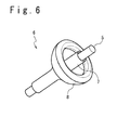
- Fig. 6 is a perspective view showing a drip-proof member 6 pertaining to the present embodiment
- Fig. 7A is its sectional view.
- the configuration of the barb portion 8 is revised. Since the other configurations can be similar to the first embodiment, detailed explanations will be omitted.
- a return portion 8-3 is added to the barb portion 8.
- the return portion 8-3 links to an outer edge of the upper surface 8-1 and extends to the cylinder part 5 side from the outer edge. Also, the return portion 8-3 is bent such that a tip portion is oriented to an end portion of the cable 5. That is, the return portion 8-3 has a hooked shape.
- the barb portion 8 receives the liquid droplets.
- the liquid droplets can be prevented from reaching the connector 2.
- liquid 9 (refer to Fig. 7A ) received by the barb portion 8 can be prevented from spilling out.
- the liquid droplets are surely prevented from entering into the connector 2.
- the return portion 8-3 is preferably provided over the entire circumference of the outer edge of the upper surface 8-1. If the return portion 8-3 is provided over the entire circumference, the liquid 9 can be further surely prevented from spilling out. However, the return portion 8-3 may be provided only on a part of the entire circumference of the outer edge.
- Fig. 7B is a sectional view showing a drip-proof member 6 pertaining to this variation example.
- a water absorption member 13 is added.
- the water absorption member 13 is arranged in a concave portion formed by the return portion 8-3. Since the water absorption member 13 is arranged, on the outer edge (tip portion) of the upper surface 8-1, the liquid 9 is absorbed by the water absorption member 13. As a result, the liquid 9 can be further surely prevented from spilling out from the barb portion 8.
- the water absorption member 13 may be arranged on the upper surface 8-1, as shown in Fig. 7C . Even in the case where the water absorption member 13 is arranged at such a position, the liquid received in the barb portion 8 is absorbed, and the liquid can be prevented from spilling out from the barb portion 8.
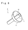
- Fig. 8 is a perspective view showing a drip-proof member 6 pertaining to the present embodiment.
- Fig. 9A is a view showing the drip-proof member 6 when seen along an axial direction of the cylinder part 7.
- a slit portion 10 is provided in the cylinder part 7 and the barb portion 8.
- the cylinder part 7 and the barb portion 8 are made of elastic materials.
- the other configurations can be similar to the already-described embodiments. Thus, detailed explanations will be omitted.
- the slit portion 10 extends from one end of the cylinder part 7 to the other end of the cylinder part 7. As shown in Fig. 9A , the slit portion 10 is arranged so that the cylinder part 7 and the barb portion 8 can be opened in the circumferential direction. That is, the drip-proof member 6 pertaining to the present embodiment can be opened in the circumferential direction at the slit portion 10.
- Fig. 9B is an explanation view for explaining a method of attaching the drip-proof member 6. As shown in Fig. 9B , after the drip-proof member 6 is opened in the circumferential direction, the drip-proof member 6 is attached to the cable 5 so that the cable 5 is covered by the cylinder part 7.
- the drip-proof member 6 can be opened in the circumferential direction. For this reason, even after the cable 5 is connected to the connector 2 or the like, the drip-proof member 6 can be attached to the cable 5.
- the elastic material is used as the drip-proof member 6.
- the plastic, the rubber, the shrinkage sleeve and the like can be used.
- the material of the drip-proof member 6 has a property which enables the inner circumferential surface of the cylinder part 7 to be adhered to the cable 5 without any gap. From this viewpoint, a shrink sleeve is preferable, rubber is secondarily preferable, and plastic is thirdly preferable.
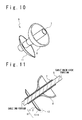
- Fig. 10 is a perspective view showing the drip-proof member 6 pertaining to the present embodiment.
- Fig. 11 is a sectional view showing the drip-proof member 6. As shown in Figs. 10 and 11 , in this embodiment, a drainer part 11 is added. Since the other configurations can be similar to the first embodiment, detailed explanations will be omitted.
- the drainer part 11 is provided so that the liquid overflowed from the barb portion 8 is separated from the cable 5. As shown in Figs. 10 and 11 , the drainer part 11 is coupled to the cylinder part 7 at a position nearer to the end of the cable 5 than the barb portion 8.
- the drainer part 11 has a drainer upper surface 11-1 and a drainer under surface 11-2.
- the cylinder part 7 penetrates through the drainer part 11 from the drainer upper surface 11-1 to the drainer under surface 11-2.
- the drainer upper surface 11-1 is concave-shaped.
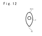
- Fig. 12 is a view showing the drainer part 11 when seen from the back-side of the cable 5. Illustration of the barb portion 8 is omitted. As shown in Figs. 11 and 12 , an edge of the drainer upper surface 11-1 has a corner 12 of a sharp angle. The drip-proof member 6 is attached to the cable 5 so that the corner 12 is downward side in vertical direction (refer to Fig. 11 ).
- the overflowed liquid is received by the drainer part 11.
- the corner 12 is provided to be oriented to the perpendicularly downward side, the received liquids drop from the corner 12 and do not run down the cable 5. Accordingly, the liquid droplets are further surely prevented from entering into the cable.
Landscapes
- Connector Housings Or Holding Contact Members (AREA)
- Insulated Conductors (AREA)
- Cable Accessories (AREA)
Abstract
Description
- This present invention relates to a connector drip-proof member and a cable structure.
- In order to electrically connect electric equipments, a cable structure is used. The cable structure contains a cable and a connector connected to an end of the cable. In the cable structure, there is a case where a water drop is generated on the cable by condensation. When the water drop runs down the cable to enter into the connector, electric connection may be disturbed. So, a water-proof means is provided in the cable structure.
- As an example of the water-proof means, a drip loop can be listed.
Figs. 1A and 1B show examples of the cable structure in which the drip loop is provided, respectively. A cable structure 100 shown inFig. 1A has acable 101 and aconnector 102 attached to one end of thecable 101. Thecable 101 is bent at the vicinity of theconnector 102, and adrip loop 103 is formed thereby. Similarly, the cable structure 100 shown inFig. 1B has thecable 101 and theconnector 102. Theconnector 102 is arranged to be downward. Thecable 101 is bent at the vicinity of the connector to be convex upward, and thedrip loop 103 is formed thereby. Since thedrip loop 103 is formed, the water drop on thecable 101 is prevented from reaching theconnector 102. - As another example of the water-proof means, potting can be listed.
Fig. 2 is a schematic view showing the other example of the cable structure. In the cable structure shown inFig. 2 , apotting portion 104 is provided to cover a connection portion between thecable 101 and theconnector 102. Thepotting portion 104 prevents liquid droplets on thecable 101 from entering into theconnector 102. - Also, a different related technique is described in a patent literature 1 (Japanese Unexamined Utility Model (Registration) Application Publication No.
H06-44045 U patent literature 1 discloses a water-proof code connector that is provided with: a connector body having a plurality of blade and an outer cap fitting with the connector body. This water-proof code connector has an insertion cylinder having an opening through which an electric wire code is inserted, in the outer shell cap. On the inner wall of the insertion cylinder, a plurality of water-proof valve are circumferentially arranged at many stages for protecting the water entering into the outer shell cap. One water-proof valve is arranged on the opening side via a winding groove placed on the inner wall of the insertion cylinder. Also, the plurality of water-proof valves are arranged on the inward side of the outer shell cap via the winding groove on the inner wall of the insertion cylinder. - [Patent literature 1] Japanese Unexamined Utility Model (Registration) Application Publication No.
H06-44045 U - However, when the
drip loop 103 is arranged as shown inFig 1A and 1B , thecable 101 becomes longer than necessary. Moreover, depending on the location in which the cable structure is arranged, a space for thedrip loop 103 may not be obtained. - Further, when the
potting portion 104 is used as shown inFig.2 , the potting portion should be cured after being applied. In order to formpotting portion 104, much time is spent. Additionally, when detaching theconnecter 102 from the cable101, thepotting portion 102 should be removed and extra work is needed. - Also, according to the water-proof code connector disclosed in
patent literature 1, the outer shell cap having water-proof valves, the winding groove or the like should be manufactured. - The outer shell having a complicated structure is needed, and that brings disadvantages in a cost of manufacturing connectors.
- Accordingly, an object of the present invention is to provide a connector drip-proof member and cable structure, which can be applied to a narrow space, reduce workload for attaching, and be manufactured at low cost.
- A connector drip-proof member according to the present invention includes a cylinder part configured to be attached to a cable whose end is connected to a connector so as to cover a part of the cable, and a barb portion linked to the cylinder part and configured to prevent droplets on the cable from reaching the connector. The barb portion includes an upper surface configured to face to a back end side of the cable, and an under surface configured to face to an end side of the cable. The cylinder part penetrates the barb portion from the upper surface to the under surface. The upper surface is concave.
- According to the present invention, since the barb portion is provided, droplets are prevented from running down cable to reach the connector. Drip loops are not needed, and the connector drip-proof member can be attached to the cable even in a narrow space. Furthermore, since a potting material or the like is not needed, time is not spent in curing the potting material. Additionally, since a special structure is not necessary for the cable and the connector, waterproof processes can be conducted at low cost.
- A cable structure according to the present invention includes above mentioned drip-proof member, a cable to which the connector drip-proof member is attached, and a connector connected to an end of the cable.
- According to the present invention, a connecter drip-proof member and cable structure is provided which can be applied to a narrow space, reduce workload for attaching, and be manufactured at low cost.
-
-
Fig. 1A is a view showing one example of the cable structure in which the drip loop is provided. -
Fig. 1B is a view showing a different example of the cable structure in which the drip loop is provided. -
Fig. 2 is a schematic view showing another example of the cable structure. -
Fig. 3 is a schematic view showing a cable structure pertaining to a first embodiment. -
Fig. 4 is a perspective view showing a connector drip-proof member. -
Fig. 5 is a sectional view showing the drip-proof member for the connector. -
Fig. 6 is a perspective view showing a connector drip-proof member pertaining to a second embodiment. -
Fig. 7A is a sectional view showing the connector drip-proof member. -
Fig. 7B a sectional view showing a connector drip-proof member pertaining to a variation example of the second embodiment. -
Fig. 7C is a sectional view showing a connector drip-proof member pertaining to a different variation example of the second embodiment. -
Fig. 8 is a perspective view showing a connector drip-proof member pertaining to a third embodiment. -
Fig. 9A is a view showing the connector drip-proof member when seen along an axial direction of a cylinder part. -
Fig. 9B is an explanation view for explaining a method of attaching the drip-proof member to the connector. -
Fig. 10 is a perspective view showing a connector drip-proof member pertaining to a fourth embodiment. -
Fig. 11 is a sectional view showing a connector drip-proof member. -
Fig. 12 is a view showing a drainer part when seen from a back-side of the cable. - Embodiments of the present invention will be described below with reference to the drawings.
-
Fig. 3 is a schematic view showing acable structure 1 pertaining to the present embodiment. Thiscable structure 1 is assumed to be used to connect electronic equipments arranged in an airplane. There is a case that the attitude of the airplane changes during flight. For this reason, liquid droplets on a cable easily run down the cable. For this reason, a waterproof process against the liquid droplets running down the cable is requested. Also, a space in which thecable structure 1 can be arranged is limited. Thus, a waterproof process with small-footprint is required. - As shown in
Fig. 3 , thecable structure 1 pertaining to the present embodiment contains acable 5, aconnector 2, a back shell 3 and a connector drip-proof member 6. An edge of thecable 5 is inserted into the back shell 3. The back shell 3 is linked to theconnector 2. The edge of thecable 5 is connected to theconnector 2 via the back shell 3. As thecable 5, for example, an electric cable, an optical cable and the like are used. - The drip-
proof member 6 is provided to prevent liquid droplets on thecable 5 from reaching theconnector 2. The drip-proof member 6 is attached to thecable 5 at the vicinity of the back shell 3. -
Fig. 4 is a perspective view showing the drip-proof member 6. Also,Fig. 5 is a sectional view showing the drip-proof member 6. As shown inFigs. 4 and 5 , the drip-proof member 6 has acylinder part 7 and abarb portion 8. - The
cylinder part 7 has a cylindrical shape. Thecable 5 is inserted through thecylinder part 7. In other words, thecylinder part 7 is attached to the cable so that a part of thecable 5 is covered in the circumferential direction. - The
barb portion 8 is provided for receiving the liquid droplets running down thecable 5. Thebarb portion 8 is ball-shaped and coupled to thecylinder part 7. In detail, thebarb portion 8 has an upper surface 8-1 and an under surface 8-2, as shown inFig. 5 . The upper surface 8-1 is oriented to the back-side of thecable 5. The under surface 8-2 is oriented to the end portion of the cable. The upper surface 8-1 forms a concave surface. Thecylinder part 7 penetrates through thebarb portion 8, from the upper surface 8-1 to the under surface 8-2. - The material of the drip-
proof member 6 is not limited. As the material of the drip-proof member 6, for example, plastic, rubber, shrinkage sleeve and the like can be used. - The
above cable structure 1 can be obtained by a method described below. Before thecable 5 is connected to the back shell 3 and theconnector 2, thecable 5 is inserted through the drip-proof member 6. Next, the back shell 3 and theconnector 2 are attached to the end thecable 5. Consequently, thecable structure 1 is obtained. - According to the
cable structure 1 pertaining to the present embodiment, the liquid droplets on thecable 5 are received by thebarb portion 8. Thus, the liquid droplets are prevented from running down to enter into theconnector 2. - Also, according to the present embodiment, the water-proof process can be conducted without installation of the drip loop and the like. The length of the
cable 5 can be reduced, thereby enabling reduction in the weight of thecable structure 1. Moreover, since thecable 5 is not required to be bent, thecable structure 1 can be arranged even in a narrow space. - In addition, according to the present embodiment, the water-proof process can be conducted only by inserting the
cable 5 through the drip-proof member 6. Potting agent and the like are not required, and the water-proof process can be conducted in a short time. Also, since the potting agent and the like are not used at a connection part between theconnector 2 and thecable 5, a special work is not required for detaching theconnector 2 from thecable 5. - Also, according to the present embodiment, a special configuration is not required in the
connector 2 and the back shell 3. Accordingly, the manufacturing cost of theconnector 2 and the back shell 3 can be suppressed. - In this embodiment, a case is explained in which the
cable structure 1 is arranged inside the airplane. However, thecable structure 1 pertaining to the present embodiment is not limited to the one arranged inside the airplane, and can be applied to different fields. However, in the airplane, an installation space is limited. Also, in the airplane, many (for example, 1000 to 2000) cables are used, and reduction of weight is strongly required. Furthermore, in the airplane, the liquid droplets easily run down thecable 5 due to a change of attitude. From these viewpoints, thecable structure 1 pertaining to the present embodiment is preferably applied to airplanes. - Next, the second embodiment will be described.
Fig. 6 is a perspective view showing a drip-proof member 6 pertaining to the present embodiment, andFig. 7A is its sectional view. In this embodiment, as compared with the first embodiment, the configuration of thebarb portion 8 is revised. Since the other configurations can be similar to the first embodiment, detailed explanations will be omitted. - As shown in
Fig. 7A , in this embodiment, a return portion 8-3 is added to thebarb portion 8. The return portion 8-3 links to an outer edge of the upper surface 8-1 and extends to thecylinder part 5 side from the outer edge. Also, the return portion 8-3 is bent such that a tip portion is oriented to an end portion of thecable 5. That is, the return portion 8-3 has a hooked shape. - According to the present embodiment, as is the case in the first embodiment, the
barb portion 8 receives the liquid droplets. Thus, the liquid droplets can be prevented from reaching theconnector 2. - In addition, according to the present embodiment, since the return portion 8-3 is provided, liquid 9 (refer to
Fig. 7A ) received by thebarb portion 8 can be prevented from spilling out. Thus, the liquid droplets are surely prevented from entering into theconnector 2. - The return portion 8-3 is preferably provided over the entire circumference of the outer edge of the upper surface 8-1. If the return portion 8-3 is provided over the entire circumference, the
liquid 9 can be further surely prevented from spilling out. However, the return portion 8-3 may be provided only on a part of the entire circumference of the outer edge. - Next, the variation example of the present embodiment will be described.
-
Fig. 7B is a sectional view showing a drip-proof member 6 pertaining to this variation example. In this variation example, awater absorption member 13 is added. Thewater absorption member 13 is arranged in a concave portion formed by the return portion 8-3. Since thewater absorption member 13 is arranged, on the outer edge (tip portion) of the upper surface 8-1, theliquid 9 is absorbed by thewater absorption member 13. As a result, theliquid 9 can be further surely prevented from spilling out from thebarb portion 8. - The
water absorption member 13 may be arranged on the upper surface 8-1, as shown inFig. 7C . Even in the case where thewater absorption member 13 is arranged at such a position, the liquid received in thebarb portion 8 is absorbed, and the liquid can be prevented from spilling out from thebarb portion 8. - Next, the third embodiment will be described.
Fig. 8 is a perspective view showing a drip-proof member 6 pertaining to the present embodiment. Also,Fig. 9A is a view showing the drip-proof member 6 when seen along an axial direction of thecylinder part 7. In the present embodiment, as shown inFigs. 8 and9A , aslit portion 10 is provided in thecylinder part 7 and thebarb portion 8. Also, thecylinder part 7 and thebarb portion 8 are made of elastic materials. The other configurations can be similar to the already-described embodiments. Thus, detailed explanations will be omitted. - As shown in
Fig. 8 , theslit portion 10 extends from one end of thecylinder part 7 to the other end of thecylinder part 7. As shown inFig. 9A , theslit portion 10 is arranged so that thecylinder part 7 and thebarb portion 8 can be opened in the circumferential direction. That is, the drip-proof member 6 pertaining to the present embodiment can be opened in the circumferential direction at theslit portion 10. -
Fig. 9B is an explanation view for explaining a method of attaching the drip-proof member 6. As shown inFig. 9B , after the drip-proof member 6 is opened in the circumferential direction, the drip-proof member 6 is attached to thecable 5 so that thecable 5 is covered by thecylinder part 7. - According to the present embodiment, since the
slit portion 10 is provided, the drip-proof member 6 can be opened in the circumferential direction. For this reason, even after thecable 5 is connected to theconnector 2 or the like, the drip-proof member 6 can be attached to thecable 5. - In this embodiment, the elastic material is used as the drip-
proof member 6. As the elastic material, the plastic, the rubber, the shrinkage sleeve and the like can be used. Here, preferably, the material of the drip-proof member 6 has a property which enables the inner circumferential surface of thecylinder part 7 to be adhered to thecable 5 without any gap. From this viewpoint, a shrink sleeve is preferable, rubber is secondarily preferable, and plastic is thirdly preferable. - Next, the fourth embodiment will be described.
Fig. 10 is a perspective view showing the drip-proof member 6 pertaining to the present embodiment.Fig. 11 is a sectional view showing the drip-proof member 6. As shown inFigs. 10 and 11 , in this embodiment, adrainer part 11 is added. Since the other configurations can be similar to the first embodiment, detailed explanations will be omitted. - The
drainer part 11 is provided so that the liquid overflowed from thebarb portion 8 is separated from thecable 5. As shown inFigs. 10 and 11 , thedrainer part 11 is coupled to thecylinder part 7 at a position nearer to the end of thecable 5 than thebarb portion 8. Thedrainer part 11 has a drainer upper surface 11-1 and a drainer under surface 11-2. Thecylinder part 7 penetrates through thedrainer part 11 from the drainer upper surface 11-1 to the drainer under surface 11-2. The drainer upper surface 11-1 is concave-shaped. -
Fig. 12 is a view showing thedrainer part 11 when seen from the back-side of thecable 5. Illustration of thebarb portion 8 is omitted. As shown inFigs. 11 and12 , an edge of the drainer upper surface 11-1 has acorner 12 of a sharp angle. The drip-proof member 6 is attached to thecable 5 so that thecorner 12 is downward side in vertical direction (refer toFig. 11 ). - According to the present embodiment, even if the liquid overflows from the
barb portion 8, the overflowed liquid is received by thedrainer part 11. Here, since thecorner 12 is provided to be oriented to the perpendicularly downward side, the received liquids drop from thecorner 12 and do not run down thecable 5. Accordingly, the liquid droplets are further surely prevented from entering into the cable. - As mentioned above, the present invention has been described by the first to fourth embodiments. These embodiments and variation examples are not independent of each other. They can be used by combining in a range without any conflict.
- This application claims a priority on convention based on Japanese Patent Application No.
2010-239614 filed on October 26, 2010
Claims (7)
- A connector drip-proof member, comprising:a cylinder part configured to be attached to a cable whose end is connected to a connector such that a part of the cable is covered; anda barb portion configured to be linked to the cylinder part and configured to prevent droplets on the cable from reaching the connector,wherein the barb portion comprises:an upper surface configured to face to a back-side of the cable; andan under surface configured to face to an end side of the cable,wherein the cylinder part penetrates the barb portion from the upper surface to the under surface, andwherein the upper surface is concave.
- The connector drip-proof member according to claim 1, wherein the barb portion further comprises a return portion configured to be linked to an outer edge of the upper surface and extend to a cylinder part side from the outer edge of the upper surface.
- The connector drip-proof member according to claim 1 or 2, wherein a slit potion is provided in the cylinder part and the barb portion so that the cylinder part and barb portion can be opened along a circumferential direction.
- The connector drip-proof member according to any of claims 1 to 3, further comprising a drainer part configured to be linked to the cylinder part at a position nearer to the end of the cable than the barb portion,
wherein the drainer part comprises:a drainer upper surface facing to the back-side of cable; anda drainer under surface facing to the end side of cable,wherein the cylinder part penetrates through the drainer part from the drainer upper surface to the drainer under surface,wherein the drainer upper surface has a concave shape, andwherein a shape of outer edge of the drainer upper surface includes a corner when seen from a back-side of the cable. - The connector drip-proof member according to any of claims 1 to 4, further comprising a water absorption member configured to absorb liquid collected on the top surface of the barb.
- The connector drip-proof member according to any of claims 1 to 5, wherein the cable is arranged inside an airplane.
- A cable structure, comprising:the connector drip-proof member according to any of claims 1 to 6;a cable to which the connector drip-proof member is attached; anda connector connected to the end of the cable.
Applications Claiming Priority (2)
| Application Number | Priority Date | Filing Date | Title |
|---|---|---|---|
| JP2010239614A JP5737902B2 (en) | 2010-10-26 | 2010-10-26 | Drip-proof member for connector and cable structure |
| PCT/JP2011/074155 WO2012056988A1 (en) | 2010-10-26 | 2011-10-20 | Connector drip-proof member and cable structure |
Publications (3)
| Publication Number | Publication Date |
|---|---|
| EP2634881A1 true EP2634881A1 (en) | 2013-09-04 |
| EP2634881A4 EP2634881A4 (en) | 2014-11-19 |
| EP2634881B1 EP2634881B1 (en) | 2016-12-07 |
Family
ID=45993700
Family Applications (1)
| Application Number | Title | Priority Date | Filing Date |
|---|---|---|---|
| EP11836124.5A Not-in-force EP2634881B1 (en) | 2010-10-26 | 2011-10-20 | Connector drip-proof member and cable structure |
Country Status (6)
| Country | Link |
|---|---|
| US (1) | US9685729B2 (en) |
| EP (1) | EP2634881B1 (en) |
| JP (1) | JP5737902B2 (en) |
| BR (1) | BR112013006583B1 (en) |
| CA (1) | CA2812990C (en) |
| WO (1) | WO2012056988A1 (en) |
Families Citing this family (2)
| Publication number | Priority date | Publication date | Assignee | Title |
|---|---|---|---|---|
| JP7072349B2 (en) * | 2017-03-22 | 2022-05-20 | ダイハツ工業株式会社 | Connector retention structure |
| JP6893844B2 (en) * | 2017-07-20 | 2021-06-23 | 株式会社タチエス | Trim cover and vehicle seat |
Family Cites Families (24)
| Publication number | Priority date | Publication date | Assignee | Title |
|---|---|---|---|---|
| GB1594937A (en) * | 1976-11-03 | 1981-08-05 | Raychem Sa Nv | Sealing device and method |
| JPS61185219A (en) | 1985-02-13 | 1986-08-18 | 松下電器産業株式会社 | Juicer |
| JPH036116Y2 (en) * | 1985-05-08 | 1991-02-15 | ||
| US4719315A (en) * | 1986-01-31 | 1988-01-12 | United Ropeworks (U.S.A.) Inc. | Cable connectors |
| JPS6310990A (en) | 1986-07-02 | 1988-01-18 | Matsushita Electric Ind Co Ltd | Video camera |
| JPH0414072Y2 (en) * | 1986-07-09 | 1992-03-31 | ||
| JP3195402B2 (en) | 1992-03-26 | 2001-08-06 | 株式会社セガ | Data alignment method and apparatus |
| JPH0644045U (en) | 1992-11-20 | 1994-06-10 | 松下電工株式会社 | Waterproof cord connector |
| JP2947498B2 (en) | 1993-09-06 | 1999-09-13 | 矢崎総業株式会社 | Connection structure between flat cable and conductor |
| GB2289104B (en) * | 1994-04-21 | 1997-05-21 | Inoue Mtp Kk | Grommet |
| JPH10224958A (en) * | 1997-02-07 | 1998-08-21 | Sumitomo Wiring Syst Ltd | Waterproof structure for wire harness in automobile |
| JPH10308585A (en) * | 1997-05-08 | 1998-11-17 | Nec Corp | Escaped water preventing structure |
| US6119305A (en) * | 1997-06-17 | 2000-09-19 | Ta Mfg Co. | Sealing elements |
| JPH1169572A (en) * | 1997-08-06 | 1999-03-09 | Denso Corp | Grommet |
| JP2000041320A (en) * | 1998-05-20 | 2000-02-08 | Yazaki Corp | Grommet |
| JP3825278B2 (en) * | 2001-05-29 | 2006-09-27 | 矢崎総業株式会社 | Grommet |
| JP3692969B2 (en) * | 2001-06-08 | 2005-09-07 | 住友電装株式会社 | Grommet line sealing method |
| US7361836B2 (en) * | 2002-06-26 | 2008-04-22 | Prysmian Cavi E Sistemi Energia S.R.L. | Method and arrangement for a termination of an electrical cable |
| JP4036135B2 (en) * | 2003-04-18 | 2008-01-23 | 住友電装株式会社 | Grommet |
| US6815615B1 (en) * | 2003-08-29 | 2004-11-09 | Yazaki North America, Inc. | Two-part grommet |
| JP4123199B2 (en) | 2004-06-29 | 2008-07-23 | 株式会社豊田自動織機 | Waterproof device for opening drive section in water jet loom |
| US20090014212A1 (en) * | 2007-07-13 | 2009-01-15 | Malak Stephen P | Micro encapsulation seal for coaxial cable connectors and method of use thereof |
| JP2009263992A (en) * | 2008-04-24 | 2009-11-12 | Panasonic Electric Works Co Ltd | Rain chain |
| US8509335B2 (en) | 2009-03-10 | 2013-08-13 | Kabushiki Kaisha Toshiba | Array antenna apparatus and micro wave transceiver module |
-
2010
- 2010-10-26 JP JP2010239614A patent/JP5737902B2/en not_active Expired - Fee Related
-
2011
- 2011-10-20 US US13/824,460 patent/US9685729B2/en not_active Expired - Fee Related
- 2011-10-20 BR BR112013006583-4A patent/BR112013006583B1/en not_active IP Right Cessation
- 2011-10-20 EP EP11836124.5A patent/EP2634881B1/en not_active Not-in-force
- 2011-10-20 WO PCT/JP2011/074155 patent/WO2012056988A1/en not_active Ceased
- 2011-10-20 CA CA2812990A patent/CA2812990C/en not_active Expired - Fee Related
Also Published As
| Publication number | Publication date |
|---|---|
| CN103125058A (en) | 2013-05-29 |
| US20130178087A1 (en) | 2013-07-11 |
| JP2012095416A (en) | 2012-05-17 |
| BR112013006583B1 (en) | 2020-03-10 |
| BR112013006583A2 (en) | 2016-06-21 |
| US9685729B2 (en) | 2017-06-20 |
| EP2634881A4 (en) | 2014-11-19 |
| CA2812990C (en) | 2016-04-05 |
| EP2634881B1 (en) | 2016-12-07 |
| JP5737902B2 (en) | 2015-06-17 |
| WO2012056988A1 (en) | 2012-05-03 |
| CA2812990A1 (en) | 2012-05-03 |
Similar Documents
| Publication | Publication Date | Title |
|---|---|---|
| EP2930795B1 (en) | Sealed connector with an extended seal sleeve and an anti-water pooling retainer | |
| EP3336992B1 (en) | Port entry device | |
| US10243335B2 (en) | Water-proofing member | |
| KR102163534B1 (en) | Fastening device for fixing a cable | |
| US9768548B2 (en) | Multicore cable and method for manufacturing the same | |
| US20150144378A1 (en) | Grommet | |
| EP2874245A1 (en) | Connector and connector connection structure | |
| CN108292834B (en) | Cable holding structure | |
| CN107810340B (en) | Bowden Cable Connection Structure for Motor Vehicle Locks | |
| EP2634881B1 (en) | Connector drip-proof member and cable structure | |
| JP2016010304A (en) | Seal member | |
| CN112585831A (en) | Holding body and wire harness | |
| US10122097B2 (en) | Molded portion-equipped electric wire | |
| US11095015B2 (en) | Locking of a roof antenna of a vehicle by means of a star wheel | |
| US9956938B2 (en) | Vehicular pop-up hood device | |
| EP2579410A1 (en) | Grommet | |
| WO2016167109A1 (en) | Waterproofing structure for electronic control unit | |
| JP2012100460A (en) | Wire harness | |
| CN103125058B (en) | Adapter drip-proof member and cable structure body | |
| US20140299720A1 (en) | Installation assembly for bridging a cable harness or the like between two aircraft structure elements | |
| EP2538496A1 (en) | Electrical connection system for a strut rod | |
| JP6070467B2 (en) | Grommet and wire harness with grommet | |
| CN106257781B (en) | Fastening device for cables | |
| CN114069933B (en) | Driving part and driving system | |
| CN109273917A (en) | With plastic shell water-proof connector female and with plastic shell water-proof connector |
Legal Events
| Date | Code | Title | Description |
|---|---|---|---|
| PUAI | Public reference made under article 153(3) epc to a published international application that has entered the european phase |
Free format text: ORIGINAL CODE: 0009012 |
|
| 17P | Request for examination filed |
Effective date: 20130318 |
|
| AK | Designated contracting states |
Kind code of ref document: A1 Designated state(s): AL AT BE BG CH CY CZ DE DK EE ES FI FR GB GR HR HU IE IS IT LI LT LU LV MC MK MT NL NO PL PT RO RS SE SI SK SM TR |
|
| DAX | Request for extension of the european patent (deleted) | ||
| A4 | Supplementary search report drawn up and despatched |
Effective date: 20141017 |
|
| RIC1 | Information provided on ipc code assigned before grant |
Ipc: H02G 15/08 20060101AFI20141013BHEP Ipc: H02G 3/22 20060101ALI20141013BHEP Ipc: H01B 7/00 20060101ALI20141013BHEP Ipc: H01B 17/58 20060101ALI20141013BHEP Ipc: H01R 13/52 20060101ALI20141013BHEP Ipc: H01B 7/282 20060101ALI20141013BHEP |
|
| GRAP | Despatch of communication of intention to grant a patent |
Free format text: ORIGINAL CODE: EPIDOSNIGR1 |
|
| INTG | Intention to grant announced |
Effective date: 20160602 |
|
| GRAS | Grant fee paid |
Free format text: ORIGINAL CODE: EPIDOSNIGR3 |
|
| GRAA | (expected) grant |
Free format text: ORIGINAL CODE: 0009210 |
|
| AK | Designated contracting states |
Kind code of ref document: B1 Designated state(s): AL AT BE BG CH CY CZ DE DK EE ES FI FR GB GR HR HU IE IS IT LI LT LU LV MC MK MT NL NO PL PT RO RS SE SI SK SM TR |
|
| REG | Reference to a national code |
Ref country code: GB Ref legal event code: FG4D |
|
| REG | Reference to a national code |
Ref country code: CH Ref legal event code: EP Ref country code: AT Ref legal event code: REF Ref document number: 852468 Country of ref document: AT Kind code of ref document: T Effective date: 20161215 |
|
| REG | Reference to a national code |
Ref country code: IE Ref legal event code: FG4D |
|
| REG | Reference to a national code |
Ref country code: DE Ref legal event code: R096 Ref document number: 602011033241 Country of ref document: DE |
|
| PG25 | Lapsed in a contracting state [announced via postgrant information from national office to epo] |
Ref country code: LV Free format text: LAPSE BECAUSE OF FAILURE TO SUBMIT A TRANSLATION OF THE DESCRIPTION OR TO PAY THE FEE WITHIN THE PRESCRIBED TIME-LIMIT Effective date: 20161207 |
|
| REG | Reference to a national code |
Ref country code: LT Ref legal event code: MG4D |
|
| REG | Reference to a national code |
Ref country code: NL Ref legal event code: MP Effective date: 20161207 |
|
| PG25 | Lapsed in a contracting state [announced via postgrant information from national office to epo] |
Ref country code: GR Free format text: LAPSE BECAUSE OF FAILURE TO SUBMIT A TRANSLATION OF THE DESCRIPTION OR TO PAY THE FEE WITHIN THE PRESCRIBED TIME-LIMIT Effective date: 20170308 Ref country code: SE Free format text: LAPSE BECAUSE OF FAILURE TO SUBMIT A TRANSLATION OF THE DESCRIPTION OR TO PAY THE FEE WITHIN THE PRESCRIBED TIME-LIMIT Effective date: 20161207 Ref country code: LT Free format text: LAPSE BECAUSE OF FAILURE TO SUBMIT A TRANSLATION OF THE DESCRIPTION OR TO PAY THE FEE WITHIN THE PRESCRIBED TIME-LIMIT Effective date: 20161207 Ref country code: NO Free format text: LAPSE BECAUSE OF FAILURE TO SUBMIT A TRANSLATION OF THE DESCRIPTION OR TO PAY THE FEE WITHIN THE PRESCRIBED TIME-LIMIT Effective date: 20170307 |
|
| REG | Reference to a national code |
Ref country code: AT Ref legal event code: MK05 Ref document number: 852468 Country of ref document: AT Kind code of ref document: T Effective date: 20161207 |
|
| PG25 | Lapsed in a contracting state [announced via postgrant information from national office to epo] |
Ref country code: HR Free format text: LAPSE BECAUSE OF FAILURE TO SUBMIT A TRANSLATION OF THE DESCRIPTION OR TO PAY THE FEE WITHIN THE PRESCRIBED TIME-LIMIT Effective date: 20161207 Ref country code: ES Free format text: LAPSE BECAUSE OF FAILURE TO SUBMIT A TRANSLATION OF THE DESCRIPTION OR TO PAY THE FEE WITHIN THE PRESCRIBED TIME-LIMIT Effective date: 20161207 Ref country code: RS Free format text: LAPSE BECAUSE OF FAILURE TO SUBMIT A TRANSLATION OF THE DESCRIPTION OR TO PAY THE FEE WITHIN THE PRESCRIBED TIME-LIMIT Effective date: 20161207 Ref country code: FI Free format text: LAPSE BECAUSE OF FAILURE TO SUBMIT A TRANSLATION OF THE DESCRIPTION OR TO PAY THE FEE WITHIN THE PRESCRIBED TIME-LIMIT Effective date: 20161207 |
|
| PG25 | Lapsed in a contracting state [announced via postgrant information from national office to epo] |
Ref country code: NL Free format text: LAPSE BECAUSE OF FAILURE TO SUBMIT A TRANSLATION OF THE DESCRIPTION OR TO PAY THE FEE WITHIN THE PRESCRIBED TIME-LIMIT Effective date: 20161207 |
|
| PG25 | Lapsed in a contracting state [announced via postgrant information from national office to epo] |
Ref country code: IS Free format text: LAPSE BECAUSE OF FAILURE TO SUBMIT A TRANSLATION OF THE DESCRIPTION OR TO PAY THE FEE WITHIN THE PRESCRIBED TIME-LIMIT Effective date: 20170407 Ref country code: SK Free format text: LAPSE BECAUSE OF FAILURE TO SUBMIT A TRANSLATION OF THE DESCRIPTION OR TO PAY THE FEE WITHIN THE PRESCRIBED TIME-LIMIT Effective date: 20161207 Ref country code: EE Free format text: LAPSE BECAUSE OF FAILURE TO SUBMIT A TRANSLATION OF THE DESCRIPTION OR TO PAY THE FEE WITHIN THE PRESCRIBED TIME-LIMIT Effective date: 20161207 Ref country code: RO Free format text: LAPSE BECAUSE OF FAILURE TO SUBMIT A TRANSLATION OF THE DESCRIPTION OR TO PAY THE FEE WITHIN THE PRESCRIBED TIME-LIMIT Effective date: 20161207 Ref country code: CZ Free format text: LAPSE BECAUSE OF FAILURE TO SUBMIT A TRANSLATION OF THE DESCRIPTION OR TO PAY THE FEE WITHIN THE PRESCRIBED TIME-LIMIT Effective date: 20161207 |
|
| PG25 | Lapsed in a contracting state [announced via postgrant information from national office to epo] |
Ref country code: BE Free format text: LAPSE BECAUSE OF FAILURE TO SUBMIT A TRANSLATION OF THE DESCRIPTION OR TO PAY THE FEE WITHIN THE PRESCRIBED TIME-LIMIT Effective date: 20161207 Ref country code: PL Free format text: LAPSE BECAUSE OF FAILURE TO SUBMIT A TRANSLATION OF THE DESCRIPTION OR TO PAY THE FEE WITHIN THE PRESCRIBED TIME-LIMIT Effective date: 20161207 Ref country code: PT Free format text: LAPSE BECAUSE OF FAILURE TO SUBMIT A TRANSLATION OF THE DESCRIPTION OR TO PAY THE FEE WITHIN THE PRESCRIBED TIME-LIMIT Effective date: 20170407 Ref country code: IT Free format text: LAPSE BECAUSE OF FAILURE TO SUBMIT A TRANSLATION OF THE DESCRIPTION OR TO PAY THE FEE WITHIN THE PRESCRIBED TIME-LIMIT Effective date: 20161207 Ref country code: BG Free format text: LAPSE BECAUSE OF FAILURE TO SUBMIT A TRANSLATION OF THE DESCRIPTION OR TO PAY THE FEE WITHIN THE PRESCRIBED TIME-LIMIT Effective date: 20170307 Ref country code: AT Free format text: LAPSE BECAUSE OF FAILURE TO SUBMIT A TRANSLATION OF THE DESCRIPTION OR TO PAY THE FEE WITHIN THE PRESCRIBED TIME-LIMIT Effective date: 20161207 Ref country code: SM Free format text: LAPSE BECAUSE OF FAILURE TO SUBMIT A TRANSLATION OF THE DESCRIPTION OR TO PAY THE FEE WITHIN THE PRESCRIBED TIME-LIMIT Effective date: 20161207 |
|
| REG | Reference to a national code |
Ref country code: DE Ref legal event code: R097 Ref document number: 602011033241 Country of ref document: DE |
|
| PLBE | No opposition filed within time limit |
Free format text: ORIGINAL CODE: 0009261 |
|
| STAA | Information on the status of an ep patent application or granted ep patent |
Free format text: STATUS: NO OPPOSITION FILED WITHIN TIME LIMIT |
|
| REG | Reference to a national code |
Ref country code: FR Ref legal event code: PLFP Year of fee payment: 7 |
|
| 26N | No opposition filed |
Effective date: 20170908 |
|
| PG25 | Lapsed in a contracting state [announced via postgrant information from national office to epo] |
Ref country code: SI Free format text: LAPSE BECAUSE OF FAILURE TO SUBMIT A TRANSLATION OF THE DESCRIPTION OR TO PAY THE FEE WITHIN THE PRESCRIBED TIME-LIMIT Effective date: 20161207 Ref country code: DK Free format text: LAPSE BECAUSE OF FAILURE TO SUBMIT A TRANSLATION OF THE DESCRIPTION OR TO PAY THE FEE WITHIN THE PRESCRIBED TIME-LIMIT Effective date: 20161207 |
|
| PG25 | Lapsed in a contracting state [announced via postgrant information from national office to epo] |
Ref country code: MC Free format text: LAPSE BECAUSE OF FAILURE TO SUBMIT A TRANSLATION OF THE DESCRIPTION OR TO PAY THE FEE WITHIN THE PRESCRIBED TIME-LIMIT Effective date: 20161207 |
|
| REG | Reference to a national code |
Ref country code: CH Ref legal event code: PL |
|
| GBPC | Gb: european patent ceased through non-payment of renewal fee |
Effective date: 20171020 |
|
| REG | Reference to a national code |
Ref country code: IE Ref legal event code: MM4A |
|
| PG25 | Lapsed in a contracting state [announced via postgrant information from national office to epo] |
Ref country code: GB Free format text: LAPSE BECAUSE OF NON-PAYMENT OF DUE FEES Effective date: 20171020 Ref country code: LU Free format text: LAPSE BECAUSE OF NON-PAYMENT OF DUE FEES Effective date: 20171020 Ref country code: CH Free format text: LAPSE BECAUSE OF NON-PAYMENT OF DUE FEES Effective date: 20171031 Ref country code: LI Free format text: LAPSE BECAUSE OF NON-PAYMENT OF DUE FEES Effective date: 20171031 |
|
| PG25 | Lapsed in a contracting state [announced via postgrant information from national office to epo] |
Ref country code: MT Free format text: LAPSE BECAUSE OF NON-PAYMENT OF DUE FEES Effective date: 20171020 |
|
| REG | Reference to a national code |
Ref country code: FR Ref legal event code: PLFP Year of fee payment: 8 |
|
| PG25 | Lapsed in a contracting state [announced via postgrant information from national office to epo] |
Ref country code: IE Free format text: LAPSE BECAUSE OF NON-PAYMENT OF DUE FEES Effective date: 20171020 |
|
| PG25 | Lapsed in a contracting state [announced via postgrant information from national office to epo] |
Ref country code: HU Free format text: LAPSE BECAUSE OF FAILURE TO SUBMIT A TRANSLATION OF THE DESCRIPTION OR TO PAY THE FEE WITHIN THE PRESCRIBED TIME-LIMIT; INVALID AB INITIO Effective date: 20111020 |
|
| PG25 | Lapsed in a contracting state [announced via postgrant information from national office to epo] |
Ref country code: CY Free format text: LAPSE BECAUSE OF NON-PAYMENT OF DUE FEES Effective date: 20161207 |
|
| PG25 | Lapsed in a contracting state [announced via postgrant information from national office to epo] |
Ref country code: MK Free format text: LAPSE BECAUSE OF FAILURE TO SUBMIT A TRANSLATION OF THE DESCRIPTION OR TO PAY THE FEE WITHIN THE PRESCRIBED TIME-LIMIT Effective date: 20161207 |
|
| PG25 | Lapsed in a contracting state [announced via postgrant information from national office to epo] |
Ref country code: TR Free format text: LAPSE BECAUSE OF FAILURE TO SUBMIT A TRANSLATION OF THE DESCRIPTION OR TO PAY THE FEE WITHIN THE PRESCRIBED TIME-LIMIT Effective date: 20161207 |
|
| PG25 | Lapsed in a contracting state [announced via postgrant information from national office to epo] |
Ref country code: AL Free format text: LAPSE BECAUSE OF FAILURE TO SUBMIT A TRANSLATION OF THE DESCRIPTION OR TO PAY THE FEE WITHIN THE PRESCRIBED TIME-LIMIT Effective date: 20161207 |
|
| PGFP | Annual fee paid to national office [announced via postgrant information from national office to epo] |
Ref country code: DE Payment date: 20201006 Year of fee payment: 10 |
|
| PGFP | Annual fee paid to national office [announced via postgrant information from national office to epo] |
Ref country code: FR Payment date: 20210913 Year of fee payment: 11 |
|
| REG | Reference to a national code |
Ref country code: DE Ref legal event code: R119 Ref document number: 602011033241 Country of ref document: DE |
|
| PG25 | Lapsed in a contracting state [announced via postgrant information from national office to epo] |
Ref country code: DE Free format text: LAPSE BECAUSE OF NON-PAYMENT OF DUE FEES Effective date: 20220503 |
|
| PG25 | Lapsed in a contracting state [announced via postgrant information from national office to epo] |
Ref country code: FR Free format text: LAPSE BECAUSE OF NON-PAYMENT OF DUE FEES Effective date: 20221031 |