EP2634845A1 - Coating and lithiation of inorganic oxidants by reaction with lithiated reductants - Google Patents
Coating and lithiation of inorganic oxidants by reaction with lithiated reductants Download PDFInfo
- Publication number
- EP2634845A1 EP2634845A1 EP12157429.7A EP12157429A EP2634845A1 EP 2634845 A1 EP2634845 A1 EP 2634845A1 EP 12157429 A EP12157429 A EP 12157429A EP 2634845 A1 EP2634845 A1 EP 2634845A1
- Authority
- EP
- European Patent Office
- Prior art keywords
- coating
- reductant
- metallated
- transition metal
- electroactive material
- Prior art date
- Legal status (The legal status is an assumption and is not a legal conclusion. Google has not performed a legal analysis and makes no representation as to the accuracy of the status listed.)
- Granted
Links
Images


Classifications
-
- H—ELECTRICITY
- H01—ELECTRIC ELEMENTS
- H01M—PROCESSES OR MEANS, e.g. BATTERIES, FOR THE DIRECT CONVERSION OF CHEMICAL ENERGY INTO ELECTRICAL ENERGY
- H01M4/00—Electrodes
- H01M4/02—Electrodes composed of, or comprising, active material
- H01M4/36—Selection of substances as active materials, active masses, active liquids
- H01M4/48—Selection of substances as active materials, active masses, active liquids of inorganic oxides or hydroxides
- H01M4/485—Selection of substances as active materials, active masses, active liquids of inorganic oxides or hydroxides of mixed oxides or hydroxides for inserting or intercalating light metals, e.g. LiTi2O4 or LiTi2OxFy
-
- C—CHEMISTRY; METALLURGY
- C01—INORGANIC CHEMISTRY
- C01G—COMPOUNDS CONTAINING METALS NOT COVERED BY SUBCLASSES C01D OR C01F
- C01G31/00—Compounds of vanadium
-
- C—CHEMISTRY; METALLURGY
- C01—INORGANIC CHEMISTRY
- C01G—COMPOUNDS CONTAINING METALS NOT COVERED BY SUBCLASSES C01D OR C01F
- C01G45/00—Compounds of manganese
- C01G45/20—Compounds containing manganese, with or without oxygen or hydrogen, and containing one or more other elements
- C01G45/22—Compounds containing manganese, with or without oxygen or hydrogen, and containing two or more other elements
-
- C—CHEMISTRY; METALLURGY
- C01—INORGANIC CHEMISTRY
- C01G—COMPOUNDS CONTAINING METALS NOT COVERED BY SUBCLASSES C01D OR C01F
- C01G49/00—Compounds of iron
- C01G49/009—Compounds containing iron, with or without oxygen or hydrogen, and containing two or more other elements
-
- H—ELECTRICITY
- H01—ELECTRIC ELEMENTS
- H01M—PROCESSES OR MEANS, e.g. BATTERIES, FOR THE DIRECT CONVERSION OF CHEMICAL ENERGY INTO ELECTRICAL ENERGY
- H01M10/00—Secondary cells; Manufacture thereof
- H01M10/05—Accumulators with non-aqueous electrolyte
- H01M10/052—Li-accumulators
-
- H—ELECTRICITY
- H01—ELECTRIC ELEMENTS
- H01M—PROCESSES OR MEANS, e.g. BATTERIES, FOR THE DIRECT CONVERSION OF CHEMICAL ENERGY INTO ELECTRICAL ENERGY
- H01M4/00—Electrodes
- H01M4/02—Electrodes composed of, or comprising, active material
- H01M4/36—Selection of substances as active materials, active masses, active liquids
- H01M4/48—Selection of substances as active materials, active masses, active liquids of inorganic oxides or hydroxides
- H01M4/50—Selection of substances as active materials, active masses, active liquids of inorganic oxides or hydroxides of manganese
- H01M4/505—Selection of substances as active materials, active masses, active liquids of inorganic oxides or hydroxides of manganese of mixed oxides or hydroxides containing manganese for inserting or intercalating light metals, e.g. LiMn2O4 or LiMn2OxFy
-
- H—ELECTRICITY
- H01—ELECTRIC ELEMENTS
- H01M—PROCESSES OR MEANS, e.g. BATTERIES, FOR THE DIRECT CONVERSION OF CHEMICAL ENERGY INTO ELECTRICAL ENERGY
- H01M4/00—Electrodes
- H01M4/02—Electrodes composed of, or comprising, active material
- H01M4/36—Selection of substances as active materials, active masses, active liquids
- H01M4/58—Selection of substances as active materials, active masses, active liquids of inorganic compounds other than oxides or hydroxides, e.g. sulfides, selenides, tellurides, halogenides or LiCoFy; of polyanionic structures, e.g. phosphates, silicates or borates
- H01M4/5825—Oxygenated metallic salts or polyanionic structures, e.g. borates, phosphates, silicates, olivines
-
- H—ELECTRICITY
- H01—ELECTRIC ELEMENTS
- H01M—PROCESSES OR MEANS, e.g. BATTERIES, FOR THE DIRECT CONVERSION OF CHEMICAL ENERGY INTO ELECTRICAL ENERGY
- H01M4/00—Electrodes
- H01M4/02—Electrodes composed of, or comprising, active material
- H01M4/62—Selection of inactive substances as ingredients for active masses, e.g. binders, fillers
- H01M4/624—Electric conductive fillers
- H01M4/625—Carbon or graphite
-
- C—CHEMISTRY; METALLURGY
- C01—INORGANIC CHEMISTRY
- C01P—INDEXING SCHEME RELATING TO STRUCTURAL AND PHYSICAL ASPECTS OF SOLID INORGANIC COMPOUNDS
- C01P2002/00—Crystal-structural characteristics
- C01P2002/70—Crystal-structural characteristics defined by measured X-ray, neutron or electron diffraction data
- C01P2002/72—Crystal-structural characteristics defined by measured X-ray, neutron or electron diffraction data by d-values or two theta-values, e.g. as X-ray diagram
-
- C—CHEMISTRY; METALLURGY
- C01—INORGANIC CHEMISTRY
- C01P—INDEXING SCHEME RELATING TO STRUCTURAL AND PHYSICAL ASPECTS OF SOLID INORGANIC COMPOUNDS
- C01P2002/00—Crystal-structural characteristics
- C01P2002/80—Crystal-structural characteristics defined by measured data other than those specified in group C01P2002/70
- C01P2002/82—Crystal-structural characteristics defined by measured data other than those specified in group C01P2002/70 by IR- or Raman-data
-
- C—CHEMISTRY; METALLURGY
- C01—INORGANIC CHEMISTRY
- C01P—INDEXING SCHEME RELATING TO STRUCTURAL AND PHYSICAL ASPECTS OF SOLID INORGANIC COMPOUNDS
- C01P2002/00—Crystal-structural characteristics
- C01P2002/80—Crystal-structural characteristics defined by measured data other than those specified in group C01P2002/70
- C01P2002/84—Crystal-structural characteristics defined by measured data other than those specified in group C01P2002/70 by UV- or VIS- data
-
- C—CHEMISTRY; METALLURGY
- C01—INORGANIC CHEMISTRY
- C01P—INDEXING SCHEME RELATING TO STRUCTURAL AND PHYSICAL ASPECTS OF SOLID INORGANIC COMPOUNDS
- C01P2004/00—Particle morphology
- C01P2004/01—Particle morphology depicted by an image
- C01P2004/04—Particle morphology depicted by an image obtained by TEM, STEM, STM or AFM
-
- C—CHEMISTRY; METALLURGY
- C01—INORGANIC CHEMISTRY
- C01P—INDEXING SCHEME RELATING TO STRUCTURAL AND PHYSICAL ASPECTS OF SOLID INORGANIC COMPOUNDS
- C01P2006/00—Physical properties of inorganic compounds
- C01P2006/40—Electric properties
-
- Y—GENERAL TAGGING OF NEW TECHNOLOGICAL DEVELOPMENTS; GENERAL TAGGING OF CROSS-SECTIONAL TECHNOLOGIES SPANNING OVER SEVERAL SECTIONS OF THE IPC; TECHNICAL SUBJECTS COVERED BY FORMER USPC CROSS-REFERENCE ART COLLECTIONS [XRACs] AND DIGESTS
- Y02—TECHNOLOGIES OR APPLICATIONS FOR MITIGATION OR ADAPTATION AGAINST CLIMATE CHANGE
- Y02E—REDUCTION OF GREENHOUSE GAS [GHG] EMISSIONS, RELATED TO ENERGY GENERATION, TRANSMISSION OR DISTRIBUTION
- Y02E60/00—Enabling technologies; Technologies with a potential or indirect contribution to GHG emissions mitigation
- Y02E60/10—Energy storage using batteries
Definitions
- the present invention concerns conductive microparticles suitable for being used in electrodes of lithium ion batteries as well as methods for the production of such miroparticles and electrodes.
- the electroactive materials of electrodes of lithium ion batteries comprise at least one transition metal providing exchangeable valence electrons, said material also allowing insertion and removal or intercalation and deintercalation, respectively, of alkaline metal ions in order to keep neutrality of the material in case of exchange of valence electrons.
- electroactive materials are not or not adequately conductive per se. Such materials are used in the form of microparticles (also termed microparticulate form) or nanoparticles (also termed nanoparticulate form) and in combination with a conductive matrix. Additional improvement is obtained if the particles are conductively coated.
- conductive coatings add to the structural integrity of the particels because of improved regularity of electric field distribution on the surface of the particles and therewith connected improved structural integrity.
- the carbon coating proved advantageous. This may be due to encapsulation of the disintegrated particles and - if breaking apart - in partially conductively coated fragments.
- Methods for providing microparticles with a conductive coating are known.
- the preferred coating is a coating with carbonaceous material.
- Carbon and carbonaceous materials are known as good electrical conductors and are already used to increase the electronic conductivity of electroactive materials.
- carbon coating of oxide materials is carried out using a pyrolysis process that forms a thin layer of carbonaceous material such as pyrolitic graphite on the surface of particles provided that the electroactive core material is sufficiently stable in reducing atmosphere (see US 6,962,266 ).
- the carbonaceous coating may be obtained through thermal decomposition or through dehydrogenation, e.g. by partial oxidation of organic materials such as hydrocarbons and their derivatives like polycyclic aromatic moieties, sugars, carbon hydride and polymers.
- a lithium salt of carboxylic acids is used for simultaneous lithiation and pyrolytic carbonatious coating formation.
- the problem with the coatings of the state of the art is that the pyrolysis reaction is not well defined.
- the hydrocarbon or carboxylic acid deposits may release compounds in different stats of oxidation/reduction like hydrogen or water and carbon oxides or dioxides resulting in an inhomogeneous coating of not clearly defined composition and possibly in affected EAMs.
- the method for producing conductively coated particles comprising an at least partially metallated electroactive core material is manifested by comprising the steps of premixing an oxidant electroactive material with a metallated reductant followed by chemically reacting the oxidant electroactive material with the metallated reductant, said reductant being a coating precursor, said metal being at least one alkaline and/or at least one alkaline earth metal, and said chemically reacting being performed under conditions allowing reduction and metallation of the electroactive material via insertion/intercalation of the alkalinemetal cation(s) and/or the alkaline earth metal cation(s) and coating formation via a polymerisation reaction, like polyanionic or radicalic polymerisation, of the reductant.
- insertion and intercalation or deinsertion and deintercalation are used interchangeably for both crystalline and amorphous materials.
- a metal comprising compound is termed metallated.
- Insertion or intercalation, respectively, of different alkaline and/or alkaline earth metals at the same time like Li and Na and/or K can lead to a more stable system.
- mixed metallated reductants like Li 2-x Na x C 2 (x ⁇ 1) and/or Li 2-x K x C 2 (x ⁇ 1) is also of interest.
- the metallated reductant comprises or consists of alkaline metal(s), wherein the alkaline metal(s) comprises at least 50 % lithium, preferably at least 95 % lithium, more preferred at least 99 % lithium.
- lithium is mentioned although besides of lithium sodium and potassium may also be present, or alkaline earth metals alone or in combination with alkaline metals.
- the method of the present invention is a one step method that allows simultaneous lithiation and coating of inorganic oxidants.
- the coating is not limited to carbon although carbon is preferred but may e.g. also be a boron nitride or a carbon nitride coating.
- the conditions allowing reduction and lithiation comprise applying energy in the form of
- the chemical reaction can be induced either via thermal treatment of via tribological treatment, e.g. by ball milling. Both methods lead to conductively coated particles comprising an at least partially lithiated electroactive core material, but to different core materials. While heat treatment produces a crystalline at least partially lithiated electroactive core material, ball milling results in an almost amorphous at least partially lithiated electroactive core material. This difference in the at least partially lithiated electroactive core material, i.e. whether it is crystalline or amorphous, has a strong influence on the electrochemical behavior.
- the reaction is a redox reaction of the form M x reductant + oxidant ⁇ M x oxidant reduced + reductant surface (reductant oxidized )
- the electroactive material or electroactive core material or oxidant is abbreviated as EAM and the at least partially lithiated electroactive core material as LiEAM.
- the carbon coating takes place via a stoichiometric reaction according to the equation 1: x Li 2 C 2 + Oxidant ⁇ Li 2x Oxidant reduced + 2x C surface
- Boron nitride coating and lithiation of formally inorganic oxidants may be obtained by reaction with Li 3 BN 2 according to the following equation 2: x Li 3 BN 2 + Oxidant ⁇ Li 3x Oxidant reduced + x BN surface + x/2 N 2
- Carbon nitride coating and lithiation of formally inorganic oxidants may be obtained by reaction with Li 2 CN 2 according to the following equation 3: x Li 2 CN 2 +Oxidant ⁇ Li 2x Oxidant reduced + x CN 2x-y surface y/2 N 2
- the EAMs preferably are in the form of microparticles or even nanoparticles. Usually they have average diameters below 10 ⁇ m, preferably below 5 ⁇ m, more preferred below 1 ⁇ m and especially below 500 nm, in particular they are nanoparticles having an average particle size in the range of 5 to 500 nm, preferably in the range of 5 to 400 nm, more preferred in the range of 20 to 300 nm.
- the lithium providing reductants are preferably of small size.
- lithium carbide (Li 2 C 2 ) after synthesis has a particle size of 10 to 100 ⁇ m. Since an as small as possible particle size is assumed to improve homogeneity of the coating, it is reduced in size, e.g. by ball milling for 1 hour with 500rpm, to end up with a homogeneous particle size of 1-5 ⁇ m. Particle sizes of ⁇ 10 ⁇ m, preferably 100 nm to 5 ⁇ m, more preferred 0.5 to 1.5 ⁇ m are generally preferred for all Li and coating providing reductants.
- carbon is presently preferred due to its conductivity that is better than the one of CN and BN and because of the good availability of suitable metallated precursors.
- the thickness of the coating can only be varied by variation of the particle size of the EAM or - for thinner coatings - by starting from an EAM that has already been partially lithiated.
- the amount of surface carbon corresponds to the amount of lithium taken up by the EAM. Since big particles have a higher ratio between volume and surface, as a rule the coating will be much thicker for big particles. The minimal thickness of 2 nm so far was observed for a 40 nm particle of LiFePO 4 and a maximum thickness of 30 nm for a 5 ⁇ m large particle of LiV 2 O 5 .
- the thickness of a coating is assumed to be below 1 nm but presumably above 0.5 nm because the product deposited is not graphene.
- the coating is protecting the EAM and therewith enhancing the cycle stability.
- the average thickness of the coating is preferably between 0.5 to 30 nm, more preferred between 0.5 to 2 nm.
- the ideal thickness of the carbon coating is just thick enough to
- the reactants preferably are carefully premixed, in order to ensure that the reaction is started with homogeneously mixed starting materials.
- the whole reaction, also the premixing can and preferably is performed in the absence of any solvent thereby avoiding any solvent removal step.
- reaction starts directly.
- Suitable reaction conditions for this tribochemical step are e.g. a rotation speed of 200-1500rpm during 15 to 45 minutes, such as around 30 minutes or 30 minutes. Hitherto optimal products were obtained with 400 rpm during 30 minutes.
- the ratio between the weight of the balls and the weight of the sample which with the presently used equipment was found to be in the range from 6 : 1 to 4 : 1, preferably around 5 : 1 like 5.2 : 1 to 4.8 : 1.
- the material of the balls is irrelevant, provided that it is sufficiently hard.
- suitable materials are: Agate, a modification of silica, steal, Cr 2 O 3 , and Al 2 O 3
- the ball milling method therefore is also applicable for heat sensitive materials as H 2 V 3 O 8 without risking decomposition.
- the disadvantage of the ballmilling method is that the conditions are more difficult to adjust and that therefore it is more difficult to avoid side reactions (see below).
- the ball milling method results in an amorphous material.
- Heat treatment can be performed with fast heating rate of for example between 150 to 200 K/h like 180 K/h.
- heat treatment is performed either with a slow heating rate or with high heating rate for an initial phase followed by a slow heating rate.
- a slow heating rate of e.g. between 50 to 70 K/h should be applied for about at least the last hour, i.e. starting at 50 to 70 K below the reaction temperature.
- a presently preferred heating rate is around 60 K/h starting at about 60 K before reaching the reaction temperature.
- the fast heating rate for example may be between 150 to 200 K/h such as 180 K/h.
- the reaction temperature depends on the EAM and can easily be determined by thermogravimetry at a heating rate of e.g. 10K/min.
- the advantage of the heat treatment are the very precisely adjustable conditions so that side reactions can be avoided.
- the heat treatment leads to crystalline coated LiEAMs.
- electrodes can be prepared by mixing the coated LiEAM with an optionally electronically conducting binder, optionally in particulate form and optionally in the presence of conductive additives like conductive carbon.
- the binding of the particulate coated LiEAM can be performed in a solvent followed by drying.
- Suitable binders are polyvinylidene fluoride (PVDF), poly(3,4-ethylenedioxythiophene) (PEDOT),1-cyclohexyl-3-(2-morpholinoethyl)carbodiimide metho-p-toluenesulfonate or 1-cyclohexyl-3-(2-morpholinoethyl)carbodiimide methyl-p-toluenesulfonate (CMC), polytetrafluoroethylene (PTFE), fluoro polymer rubber (FKS), styrenebutadiene rubber (SBR), polyacrylnitrile(PAN), polyurethane, polyacrylic acid, polyamide, polyacrylate, and polyvinylether.
- PVDF polyvinylidene fluoride
- PEDOT poly(3,4-ethylenedioxythiophene)
- PEDOT poly(3,4-ethylenedioxythiophene)
- CMC 1-cyclohexyl-3
- Suitable conductive carbons are SuperP® or Super P Li® Carbon (obtainable from TIMCAL) or nanofibers or nanotubes.
- Suitable solvents are a mixture of aprotic polar and aprotic apolar solvents like THF/Toluene 4:1.
- thermostability drying is preferably either performed at temperatures well above 100°C like 180°C under air, or at temperatures below 100°C like 80°C under vacuum.
- Such electrodes can be used together with any suitable anode, and an electrolyte like LiPF 6 or Li(C 2 F 5 ) 3 PF 3 (e.g. 1 M in ethylene carbonate : dimethyl carbonate 1 : 1 (w/w))
- an electrolyte like LiPF 6 or Li(C 2 F 5 ) 3 PF 3 (e.g. 1 M in ethylene carbonate : dimethyl carbonate 1 : 1 (w/w))
- these reductants may be free from oxygen and optionally free from oxygen and hydrogen which may result in better defined coatings and insertion/intercalation products.
- the method of the invention is a surface contact reaction.
- the EAM is coated.
- Possible non-EAM side-products e.g. impurities from EAM production, can be found during the coating reaction (e.g. optically due to having a colour different from black) and separated from the product if desired.
- the atom economy of the reaction is 100 % or at least close to 100 %, i.e. no metal or surface coating atom is wasted during the reaction.
- the method of the invention is a very environment friendly reaction due to the lower energy consumption and the about 100% atom economy. Especially if oxygen free reductants are used, no waste management of the exhaust (CO, NO x ) is needed.
- Another advantage of the method of the invention is that no solvent is needed in the inventive coating reaction although in some cases use of a solvent might be useful.
- the methods of the present invention lead to a predictable conversion of the coating precursor to the desired coating and predictable Li ions insertion since the reactions are stoichiometric.
- the invention also provides reactions that can be performed at low temperature and therefore are also suitable for coating temperature sensitive EAMs.
- a further advantage of the inventive methods is that they can be used to produce a variety of conductive non carbonaceous coatings.
- Galvanostatic measurements were monitored by Astrol, a program from Astrol Electronic AG.
- a potentiostat (BAT-SMAL, battery cycler) was connected using a serial cable to a personal computer (running Windows XP) via a serial/analog converter.
- the composition of all electrodes was 73% active material, 15% Super P® Carbon (obtainable from TIMCAL) and 2 % polyvinylidene fluoride (PVDF).
- the materials were mixed in a THF/Toluene 4 : 1 mixture.
- the electrodes were dried at 180°C under air. The only exception was the LiFePO 4 electrode that was dried at 80°C under vacuum. The measurements were done with fixed currents of 50A/kg.
- the electrolyte was LP30 (obtainable from Merck Chemicals), 1.4 mol/L LiPF 6 in ethylene carbonate/dimethyl carbonate 1/1 by weight. and the counter electrode was a disk of metallic lithium with a diameter of 13 mm and 0.5 mm thickness.
- the measurements were performed with a Netzsch STA 409 using corundum crucibles using a heating rate of 10K/min.
- the reference powder was corundum, too.
- the measurements show (see Figures 6 and 15 ) that there is no significant mass loss below the reaction temperature of 600°C for V 2 O 5 and 400 °C for MoO 3 . Thus the reactions are completely proceeding to the lithiated oxidants reduced and carbon.
- the starting materials indicated below were premixed in a mortar before reacted in a Fritsch Pulverisette 6 with 400 rpm for 0.5 hours and at a ratio between the weight of the balls and the weight of the sample of 1 : 5.
- Electrodes were prepared by mixing 73% coated LiEAM 15% Super P ® Carbon (obtainable from TIMCAL) and 2 % polyvinylidene fluoride (PVDF) in a THF/Toluene 4 : 1 mixture and then drying at 180°C under air, except for the LiFePO 4 electrode that was dried at 80°C under vacuum.
- coated LiEAM 15% Super P ® Carbon obtainable from TIMCAL
- PVDF polyvinylidene fluoride
Landscapes
- Chemical & Material Sciences (AREA)
- Inorganic Chemistry (AREA)
- Organic Chemistry (AREA)
- Chemical Kinetics & Catalysis (AREA)
- Electrochemistry (AREA)
- General Chemical & Material Sciences (AREA)
- Engineering & Computer Science (AREA)
- Manufacturing & Machinery (AREA)
- Crystallography & Structural Chemistry (AREA)
- Battery Electrode And Active Subsutance (AREA)
Abstract
Description
- The present invention concerns conductive microparticles suitable for being used in electrodes of lithium ion batteries as well as methods for the production of such miroparticles and electrodes.
- The electroactive materials of electrodes of lithium ion batteries comprise at least one transition metal providing exchangeable valence electrons, said material also allowing insertion and removal or intercalation and deintercalation, respectively, of alkaline metal ions in order to keep neutrality of the material in case of exchange of valence electrons.
- Some very interesting electroactive materials are not or not suficiently conductive per se. Such materials are used in the form of microparticles (also termed microparticulate form) or nanoparticles (also termed nanoparticulate form) and in combination with a conductive matrix. Additional improvement is obtained if the particles are conductively coated.
- It is assumed that conductive coatings add to the structural integrity of the particels because of improved regularity of electric field distribution on the surface of the particles and therewith connected improved structural integrity. In addition, even if the electroactive material particles are partially disintegrated over an extended number of cycles, the carbon coating proved advantageous. This may be due to encapsulation of the disintegrated particles and - if breaking apart - in partially conductively coated fragments. Methods for providing microparticles with a conductive coating are known. The preferred coating is a coating with carbonaceous material.
- Carbon and carbonaceous materials are known as good electrical conductors and are already used to increase the electronic conductivity of electroactive materials. In general, carbon coating of oxide materials is carried out using a pyrolysis process that forms a thin layer of carbonaceous material such as pyrolitic graphite on the surface of particles provided that the electroactive core material is sufficiently stable in reducing atmosphere (see
US 6,962,266 ). According toUS 6,962,266 , the carbonaceous coating may be obtained through thermal decomposition or through dehydrogenation, e.g. by partial oxidation of organic materials such as hydrocarbons and their derivatives like polycyclic aromatic moieties, sugars, carbon hydride and polymers. In some embodiments a lithium salt of carboxylic acids is used for simultaneous lithiation and pyrolytic carbonatious coating formation. - However, the problem with the coatings of the state of the art is that the pyrolysis reaction is not well defined. During pyrolysis, the hydrocarbon or carboxylic acid deposits may release compounds in different stats of oxidation/reduction like hydrogen or water and carbon oxides or dioxides resulting in an inhomogeneous coating of not clearly defined composition and possibly in affected EAMs.
- Thus, there is still a need for high energy storage materials with a good conductive coating and a method for obtaining such materials preferably in a one step reaction.
- Hence, it is a general object of the invention to provide optimized coating methods and therewith obtainable optimized carbon coated electroactive particles with a coating having improved homogeneity and purity.
- Now, in order to implement these and still further objects of the invention, which will become more readily apparent as the description proceeds, the method for producing conductively coated particles comprising an at least partially metallated electroactive core material is manifested by comprising the steps of premixing an oxidant electroactive material with a metallated reductant followed by chemically reacting the oxidant electroactive material with the metallated reductant, said reductant being a coating precursor, said metal being at least one alkaline and/or at least one alkaline earth metal, and said chemically reacting being performed under conditions allowing reduction and metallation of the electroactive material via insertion/intercalation of the alkalinemetal cation(s) and/or the alkaline earth metal cation(s) and coating formation via a polymerisation reaction, like polyanionic or radicalic polymerisation, of the reductant.
- The terms insertion and intercalation or deinsertion and deintercalation, respectively are used interchangeably for both crystalline and amorphous materials.
- A metal comprising compound is termed metallated.
- Insertion or intercalation, respectively, of different alkaline and/or alkaline earth metals at the same time like Li and Na and/or K can lead to a more stable system. Thus the use of mixed metallated reductants like Li2-x NaxC2 (x≤1) and/or Li2-xKxC2 (x≤1) is also of interest.
- In one embodiment, the metallated reductant comprises or consists of alkaline metal(s), wherein the alkaline metal(s) comprises at least 50 % lithium, preferably at least 95 % lithium, more preferred at least 99 % lithium.
- For sake of readability, in the following description lithium is mentioned although besides of lithium sodium and potassium may also be present, or alkaline earth metals alone or in combination with alkaline metals.
- The method of the present invention is a one step method that allows simultaneous lithiation and coating of inorganic oxidants. The coating is not limited to carbon although carbon is preferred but may e.g. also be a boron nitride or a carbon nitride coating. Other possible coatings comprise CBx from B=C=B4- compounds like Li4CB2, CBxNy from a lithium pyrazine precursor like Ca10-xLi2x(BN2)4(CBN)2 (see also
WO 2004/069768 ), (SyN)x from e.g. LigNS3, (CH)x (polyacetylene) for example form LiHC2. - The conditions allowing reduction and lithiation comprise applying energy in the form of
- heat
- tribological energy like (ball) milling
- ultrasound
- microwave.
- In preferred embodiments, the chemical reaction can be induced either via thermal treatment of via tribological treatment, e.g. by ball milling. Both methods lead to conductively coated particles comprising an at least partially lithiated electroactive core material, but to different core materials. While heat treatment produces a crystalline at least partially lithiated electroactive core material, ball milling results in an almost amorphous at least partially lithiated electroactive core material. This difference in the at least partially lithiated electroactive core material, i.e. whether it is crystalline or amorphous, has a strong influence on the electrochemical behavior.
- The reaction is a redox reaction of the form
Mxreductant + oxidant → Mxoxidantreduced + reductantsurface (reductantoxidized)
- In the following description, the electroactive material or electroactive core material or oxidant is abbreviated as EAM and the at least partially lithiated electroactive core material as LiEAM.
- Different to pyrolysis, the carbon coating takes place via a stoichiometric reaction according to the equation 1:
x Li2C2 + Oxidant → Li2xOxidantreduced + 2x Csurface
- Boron nitride coating and lithiation of formally inorganic oxidants may be obtained by reaction with Li3BN2 according to the following equation 2:
x Li3BN2 + Oxidant → Li3xOxidantreduced + x BNsurface + x/2 N2
- Carbon nitride coating and lithiation of formally inorganic oxidants may be obtained by reaction with Li2CN2 according to the following equation 3:
x Li2CN2 +Oxidant → Li2xOxidantreduced + x CN2x-y surface y/2 N2
- Possible Oxidants are:
Transition metal oxides MoO3, MnO2, LiMn2O4, V2O5 Hydrated transition metal oxides H2V3O8 Transition metal oxynitrides NbNO Transition metal phosphates Mx(PO4)y (M = Fe, Co, Mn, Ni) Transition metal oxides glasses Glasses containing V2O5 and MoO3 Elements S; Se; Si - The EAMs preferably are in the form of microparticles or even nanoparticles. Usually they have average diameters below 10 µm, preferably below 5 µm, more preferred below 1 µm and especially below 500 nm, in particular they are nanoparticles having an average particle size in the range of 5 to 500 nm, preferably in the range of 5 to 400 nm, more preferred in the range of 20 to 300 nm.
- Also the lithium providing reductants are preferably of small size. For example lithium carbide (Li2C2) after synthesis has a particle size of 10 to 100µm. Since an as small as possible particle size is assumed to improve homogeneity of the coating, it is reduced in size, e.g. by ball milling for 1 hour with 500rpm, to end up with a homogeneous particle size of 1-5 µm. Particle sizes of <10 µm, preferably 100 nm to 5 µm, more preferred 0.5 to 1.5 µm are generally preferred for all Li and coating providing reductants.
- Although (as shown above) other than carbon coatings can be applied via the inventive methods, carbon is presently preferred due to its conductivity that is better than the one of CN and BN and because of the good availability of suitable metallated precursors.
- The invention is now further described for a carbon coating. However, the respective information is also applicable to other coatings.
- Due to the stoichiometry of the reactions, the thickness of the coating can only be varied by variation of the particle size of the EAM or - for thinner coatings - by starting from an EAM that has already been partially lithiated. For a carbon coating starting from Li2C2, the amount of surface carbon corresponds to the amount of lithium taken up by the EAM. Since big particles have a higher ratio between volume and surface, as a rule the coating will be much thicker for big particles. The minimal thickness of 2 nm so far was observed for a 40 nm particle of LiFePO4 and a maximum thickness of 30 nm for a 5 µm large particle of LiV2O5. It was found that even the thick coating of 30 nm allows intercalation/deintercalation, although at somewhat lower speed than a thin coating. The minimal thickness of a coating is assumed to be below 1 nm but presumably above 0.5 nm because the product deposited is not graphene. In addition, it is also assumed that the coating is protecting the EAM and therewith enhancing the cycle stability. Thus, the average thickness of the coating is preferably between 0.5 to 30 nm, more preferred between 0.5 to 2 nm.
- Theoretically, the ideal thickness of the carbon coating is just thick enough to
- prevent EAMs/LiEAMs from dissolving
- prevent additional solid electrolyte interphases (SEI) growth of interphases that are formed on e.g. the cathode due to catalytic redox reactions of the electrolyte
- install reasonable surface conductivity for Li-ions and electrons
- possibly even glue the particles together.
- In any case, it was found that in most cases partial or complete intercalation of cathode materials during this process improves their electrochemical properties.
- In view of the homogeneous coverage of the particles with the carbon, some migration of the carbon on the surface of the particles is assumed.
- Irrespective of whether the reaction is performed by ball milling or heat treatment, the reactants preferably are carefully premixed, in order to ensure that the reaction is started with homogeneously mixed starting materials.
- The whole reaction, also the premixing can and preferably is performed in the absence of any solvent thereby avoiding any solvent removal step.
- In e.g. the ball milling procedure the reaction starts directly. Suitable reaction conditions for this tribochemical step are e.g. a rotation speed of 200-1500rpm during 15 to 45 minutes, such as around 30 minutes or 30 minutes. Hitherto optimal products were obtained with 400 rpm during 30 minutes. Also important is the ratio between the weight of the balls and the weight of the sample which with the presently used equipment was found to be in the range from 6 : 1 to 4 : 1, preferably around 5 : 1 like 5.2 : 1 to 4.8 : 1.
- With the exception of the weight ratio the material of the balls is irrelevant, provided that it is sufficiently hard. Examples of suitable materials are: Agate, a modification of silica, steal, Cr2O3, and Al2O3
- Since the reaction is only slightly exothermic, no raise of the overall temperature is observed during ball milling such that the tribochemical reaction is devoid of a thermal treatment.
- The ball milling method therefore is also applicable for heat sensitive materials as H2V3O8 without risking decomposition.
- The disadvantage of the ballmilling method is that the conditions are more difficult to adjust and that therefore it is more difficult to avoid side reactions (see below).
- The ball milling method results in an amorphous material.
- Heat treatment can be performed with fast heating rate of for example between 150 to 200 K/h like 180 K/h. In preferred embodiments, heat treatment is performed either with a slow heating rate or with high heating rate for an initial phase followed by a slow heating rate. A slow heating rate of e.g. between 50 to 70 K/h should be applied for about at least the last hour, i.e. starting at 50 to 70 K below the reaction temperature. A presently preferred heating rate is around 60 K/h starting at about 60 K before reaching the reaction temperature. The fast heating rate for example may be between 150 to 200 K/h such as 180 K/h.
- The reaction temperature depends on the EAM and can easily be determined by thermogravimetry at a heating rate of e.g. 10K/min.
- The advantage of the heat treatment are the very precisely adjustable conditions so that side reactions can be avoided.
- The heat treatment leads to crystalline coated LiEAMs.
- Since Li2C2 is a strong reductant care has to be taken that an intercalation takes place and not a reduction. As already indicated above, undesired side reactions have to be avoided by careful control of the reaction conditions. Such an undesired side reaction is e.g. shown in equation 4:
2 MnO2 + Li2C2 → 2 MnO + Li2O2 + C
- From the coated particulate materials described herein electrodes can be prepared by mixing the coated LiEAM with an optionally electronically conducting binder, optionally in particulate form and optionally in the presence of conductive additives like conductive carbon. The binding of the particulate coated LiEAM can be performed in a solvent followed by drying.
- Suitable binders are polyvinylidene fluoride (PVDF), poly(3,4-ethylenedioxythiophene) (PEDOT),1-cyclohexyl-3-(2-morpholinoethyl)carbodiimide metho-p-toluenesulfonate or 1-cyclohexyl-3-(2-morpholinoethyl)carbodiimide methyl-p-toluenesulfonate (CMC), polytetrafluoroethylene (PTFE), fluoro polymer rubber (FKS), styrenebutadiene rubber (SBR), polyacrylnitrile(PAN), polyurethane, polyacrylic acid, polyamide, polyacrylate, and polyvinylether.
- Suitable conductive carbons are SuperP® or Super P Li® Carbon (obtainable from TIMCAL) or nanofibers or nanotubes.
- Suitable solvents are a mixture of aprotic polar and aprotic apolar solvents like THF/Toluene 4:1.
- Dependent on the thermostability drying is preferably either performed at temperatures well above 100°C like 180°C under air, or at temperatures below 100°C like 80°C under vacuum.
- Such electrodes can be used together with any suitable anode, and an electrolyte like LiPF6 or Li(C2F5)3PF3 (e.g. 1 M in ethylene carbonate : dimethyl carbonate 1 : 1 (w/w))
- The advantages of the new methods and the therewith produced coated LiEAM are the enhanced purity due to the specific reactants. In addition, most of the carbon coating methods are performed via pyrolysis under reducing conditions in order to avoid combustion instead of pyrolysis. Therefore, it is impossible to coat numerous cathode materials which are in a high oxidation state with these methods. A separate reduction/coating will reduce the oxidation state and therefore make the EAM unuseable for cathodes.
- In case of the one step method disclosed in
US 6, 962,666 one advantage of the present method is also that due to the inventive reactions no pyrolysis takes place. Another advantage is the enhanced purity and reproducibility due to the use of metallated reductants. - In one embodiment these reductants may be free from oxygen and optionally free from oxygen and hydrogen which may result in better defined coatings and insertion/intercalation products.
- The method of the invention is a surface contact reaction. Thus, due to the specific starting materials and reaction conditions according to the invention only the EAM is coated. Possible non-EAM side-products, e.g. impurities from EAM production, can be found during the coating reaction (e.g. optically due to having a colour different from black) and separated from the product if desired. Furthermore the atom economy of the reaction is 100 % or at least close to 100 %, i.e. no metal or surface coating atom is wasted during the reaction. Compared to a pyrolysis method the method of the invention is a very environment friendly reaction due to the lower energy consumption and the about 100% atom economy. Especially if oxygen free reductants are used, no waste management of the exhaust (CO, NOx) is needed.
- Another advantage of the method of the invention is that no solvent is needed in the inventive coating reaction although in some cases use of a solvent might be useful.
- The methods of the present invention lead to a predictable conversion of the coating precursor to the desired coating and predictable Li ions insertion since the reactions are stoichiometric. The invention also provides reactions that can be performed at low temperature and therefore are also suitable for coating temperature sensitive EAMs.
- Contrary thereto the pyrolysis reaction of carboxylic acid salts will, dependent on the conditions and a specific EAM, in general lead to different compounds and to less defined coatings.
- A further advantage of the inventive methods is that they can be used to produce a variety of conductive non carbonaceous coatings.
- The invention will be better understood and objects other than those set forth above will become apparent when consideration is given to the following detailed description thereof. Such description makes reference to the annexed drawings, that show:
-
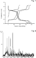
Figure 1 : X-Ray Powder Diffraction of the synthesized Li0.3V2O5 compared to the theoretical pattern. -
Figure 2 : TEM-picture of Li0.3V2O5 with carbon coating. The inter plane distance corresponds to the a-lattice parameter of Li0.3V2O5. -
Figure 3 : EDX-analysis of Li0.3V2O5 with carbon coating (EDX = Energy Dispersive X-ray Analysis). -
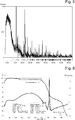
Figure 4 : Potential vs. specific charge for the Li0.3V2O5 electrode. -
Figure 5 : X-Ray Powder Diffraction of the synthesized LiV2O5 compared to the theoretical pattern. -
Figure 6 : Thermogravimetry of the reaction of Li2C2 with V2O5. -
Figure 7 : Potential vs. specific charge for the LiV2O5 electrode. -
Figure 8 : X-Ray Powder Diffraction of LiFePO4 synthesized via heat treatment (450°C) compared to the theoretical pattern. -
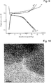
Figure 9 : Potential vs. specific charge for the via heat treatment synthesized LiFePO4 electrode. -
Figure 10 : TEM-bright field picture of LiFePO4 with carbon coating. -
Figure 11 : Indexed Fourier Transformation ofFigure 9 . -
Figure 12 : X-Ray Powder Diffraction of LiV2O5 synthesized via ball milling compared to the theoretical pattern. -
Figure 13 : Potential vs. specific charge for the via ball milling synthesized LiV2O5 electrode. -
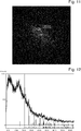
Figure 14 : TEM-bright field picture of Li0.3MoO3 with carbon coating -
Figure 15 : Thermogravimetry of the reaction of Li2C2 with MoO3via ball milling. -
Figure 16 : Potential vs. specific charge for the via ball milling synthesized Li0.3MoO3 electrode. -
Figure 17 : X-Ray Powder Diffraction of LiH2V3O8 synthesized via ball milling. -
Figure 18 : Potential vs. specific charge for the via ball milling synthesized LiH2V3O8 electrode. - Analytical and Investigation Methods:
- Galvanostatic measurements were monitored by Astrol, a program from Astrol Electronic AG. A potentiostat (BAT-SMAL, battery cycler) was connected using a serial cable to a personal computer (running Windows XP) via a serial/analog converter. The composition of all electrodes was 73% active material, 15% Super P® Carbon (obtainable from TIMCAL) and 2 % polyvinylidene fluoride (PVDF). The materials were mixed in a THF/Toluene 4 : 1 mixture. Finally the electrodes were dried at 180°C under air. The only exception was the LiFePO4 electrode that was dried at 80°C under vacuum. The measurements were done with fixed currents of 50A/kg.
- The electrolyte was LP30 (obtainable from Merck Chemicals), 1.4 mol/L LiPF6 in ethylene carbonate/
dimethyl carbonate 1/1 by weight. and the counter electrode was a disk of metallic lithium with a diameter of 13 mm and 0.5 mm thickness. - The measurements were performed with a Netzsch STA 409 using corundum crucibles using a heating rate of 10K/min. The reference powder was corundum, too. The measurements show (see
Figures 6 and15 ) that there is no significant mass loss below the reaction temperature of 600°C for V2O5 and 400 °C for MoO3. Thus the reactions are completely proceeding to the lithiated oxidantsreduced and carbon. - The measurements were performed with a STOE STADI P2 diffractometer in transmission mode with germanium monochromator, CUka1 = 1.54056 Å
- Electron microscopy was performed in a Tecnai F30 microscope (manufactured by FEI) with a field emission gun (FEG), Vacc = 300kV, and Cs = 1.2 mm
-
- Lithium granule 99.9 %, Aldrich
- Graphite powder natural microcrystal grade, APS 2-15 micron, 99.9995%, Alfa Aesar
- V2O5, 99.2%, Alfa Aesar
- FeCl3 anhydrous purum, Fluka
- H3PO4 ortho-phosphric acid 85%, Merck
- MoO3 99.5%, Sigma Aldrich
- LiMn2O4, Merck
- PVDF averabe Mw ∼ 534,000 by GPC, Sigma Aldrich
- LP30; 1 M LiPF6 in ethylene carbonate : dimethyl carbonate 1 : 1 (w/w), Merck
- LF30; 1 M Li(C2F5)3PF3 in ethylene carbonate : dimethyl carbonate 1 : 1 (w/w), Merck, highly stable
-
- FePO4 [C. Delacourt, Solid State Ionics, 173, 113-118, 2004]
- MnO2 [Asulab]
- NbNO [Nesper, R., Wang X.-J.,
EP 2 378 596 A1 ] - Glasses of V2O5 and MoO3 [
Sakurei et al. US 4,675,260 ] -
- Li2C2 [Armbruster, Dissertation (thesis), ETH Zurich No. 17553, 2008]
- LiNaC2 [R. Nesper, Habilitationsschrift, Stuttgart, 1998]
- LiKC2 [R. Nesper, Habilitationsschrift, Stuttgart, 1998]
- Li2NCN [Sokolov, Trudy po Khimii I Khimicheskoi Tekhnologii (2), 18-19, 1973]
- Li3BN2 [Yamane, Journal of Solid State Chemistry 71 (1), 1-11, 1987]
-
1.5 Li2C2 + 10 V2O5 → 10 Li0.3V2O5 + 3 Csurface
- 1.8g (10mmol) V2O5 and 0.0569g (1.5mmol) Li2C2 were mixed in a mortar. Then the mixture was heated to 600°C using a heating ramp of 180°C/h and kept at 600°C for 0.5 hours.
-
5 Li2C2 + 10 V2O5 → 10 LiV2O5 + 10 Csurface
- 1.8g (10mmol) V2O5 and 0.1895g (5mmol) Li2C2 were mixed in a mortar. Then the mixture was heated to 600°C using a heating ramp of 180°C/h and kept at 600°C for 0.5 hours.
-
3 Li2C2 + 6 FePO4 → 6 LiFePO4 + 6 Csurface
- 0.905g (6mmol) FePO4 and 0.114g (3mmol) Li2C2 were mixed in a mortar. Then the mixture was heated to 450°C using a heating ramp of 180°C/h and kept at 450°C for 2 hours.
- The starting materials indicated below were premixed in a mortar before reacted in a Fritsch Pulverisette 6 with 400 rpm for 0.5 hours and at a ratio between the weight of the balls and the weight of the sample of 1 : 5.
-
5 Li2C2 + 10 V2O5 → 10 LiV2O5 + 10 Csurface
- 1.8g (10mmol) V2O5 and 0.1895g (5mmol) Li2C2 were premixed in a mortar. Then the mixture was reacted in a Fritsch Pulverisette 6 with 400 rpm for 0.5 hours.
-
1.5 Li2C2 + 10 MoO3 → 10 Li0.3MoO3 + 3 Csurface
- 1.4394g (10mmol) MoO3 and 0.0569g (1.5mmol) Li2C2 were premixed in a mortar. Then the mixture was reacted in a Fritsch Pulverisette 6 with 400 rpm for 0.5 hours.
-
5 Li2C2 + 10 H2V3O8 → 10 LiH2V3O8 + 10 Csurface
- 2.8284g (10mmol) H2V3O8 and 0.1895g (5mmol) Li2C2 were premixed in a mortar. Then the mixture was reacted in a Fritsch Pulverisette 6 with 400 rpm for 0.5 hours.
- From the coated particulate materials described above electrodes were prepared by mixing 73% coated
LiEAM 15% Super P® Carbon (obtainable from TIMCAL) and 2 % polyvinylidene fluoride (PVDF) in a THF/Toluene 4 : 1 mixture and then drying at 180°C under air, except for the LiFePO4 electrode that was dried at 80°C under vacuum. - Analytical data and electrochemical behaviour is shown in the Figures as indicated to each example.
- While there are shown and described presently preferred embodiments of the invention, it is to be distinctly understood that the invention is not limited thereto but may be otherwise variously embodied and practiced within the scope of the following claims.
Claims (15)
- A method for producing conductively coated particles comprising an at least partially metallated electroactive core material, wherein said method comprises the steps of premixing an oxidant electroactive material with a metallated reductant followed by chemically reacting the oxidant electroactive material with the metallated reductant, said reductant being a coating precursor, said metal being atleast one alkaline and/or at least one alkaline earth metal, and said chemically reacting being performed under conditions allowing reduction and metallation of the electroactive material via insertion/intercalation of the alkaline metal cation(s) and/or the alkaline earth metal cation(s) and coating formation via a polymerisation reaction like polyanionic or radicalic polymerisation of the reductant.
- The method of claim 1 wherein said conditions comprise applying energy in the form of- heat- tribological energy like (ball) milling- ultrasound- microwave,preferably in the form of- heat- tribological energy like (ball) milling.
- The method of any of the preceding claims wherein the metal of the metallated reductant is an alkaline metal containing or consists of lithium and optionally sodium and/or potassium, preferably said alkaline metal comprises at least 50 % lithium, preferably at least 95 % lithium, more preferred at least 99 % lithium.
- The method of any of the preceding claims wherein the reductant of the metallated reductant is oxygen free.
- The method of any of the preceding claims wherein the coating and/or reductants are selected from
coating metallated coating precursor/reductant carbon Li2C2 BN Li3BN2 carbon nitride (CNX) Li2CN2 CBX Li4BCB CBxNy lithium pyrazine precursor (SyN)x LigNS3 (CH)X (polyacetylene) LiHC2 - The method of any of the preceding claims wherein the oxidants are selected from transition metal oxides, hydrated transition metal oxides, transition metal oxynitrides, transition metal phosphates, transition metal oxides glasses, elements, preferably from transition metal oxides selected from MoO3, MnO2, LiMn2O4, V2O5, or hydrated transition metal oxides selected from H2V3O8, or transition metal oxynitrides selected from NbNO, or transition metal phosphates selected from FePO4 (Co, Mn, Ni), or transition metal oxides glasses selected from Glasses containing V2O5 and MoO3, or elements selected from S, Se, Si.
- The method of any of the preceding claims wherein the oxidants are microparticles or nanoparticles having an average diameters below 10 µm, preferably below 5 µm, more preferred below 1 µm and especially below 500 nm, in particular they are nanoparticles having an average particle size in the range of 5 to 500 nm, preferably in the range of 5 to 400 nm, more preferred in the range of 20 to 300 nm, and/or wherein the metallated reductants are microparticles with an average particle size of <10 µm, preferably 100 nm to 5 µm such as 1 to 5 µm, more preferred between 0.5 to 1.5 µm.
- The method of any of the preceding claims wherein the coating has an average thickness of 0.5 nm to 30 nm, preferably between 0.5 to 2 nm.
- The method of any of the preceding claims wherein the conditions allowing reduction and lithiation of the electroactive material and coating deposition comprise a tribochemical step performed by ball milling at a rotation speed of 200-1500rpm during 15 to 45 minutes such as 30 minutes, preferably with 400 rpm during 30 minutes and/or at a ratio between the weight of the balls and the weight of the sample in the range from 6 : 1 to 4 : 1, preferably around 5 : 1 like 5.2 : 1 to 4.8 : 1.
- The method of any of claims 1 to 8 wherein the conditions allowing reduction and lithiation of the electroactive material and coating deposition comprise a heat treatment with a heating profile providing slow heating rate of between 50 to 70 K for about at least the last hour, i.e. starting at least at 50 to 70 K below the reaction temperature, preferably a heating rate of about 60 K/h starting at about 60 K before reaching the reaction temperature.
- The method of claim 10, wherein the heating profile comprises a fast heating rate of e.g. 180 K/h, preferably a fast heating rate of e.g. 180 K/h until about 60 K below reaction temperature followed by a slow heating rate of about 60K/h.
- A coated at least partially metallated, such as lithiated, particulate electroactive material obtainable by the method of any of the preceding claims, said material being crystalline or amorphous.
- An electrode comprising a coated at least partially metallated, such as lithiated, particulate electroactive material obtainable by the method of any of claims 1 to 11 comprising said coated particulate electroactive material, an optionally electronically conducting binder, optionally in particulate form and optionally in the presence of conductive additives like conductive carbon.
- A method for producing an electrode comprising a coated at least partially lithiated particulate electroactive material obtainable by the method of any of claims 1 to 11 comprising mixing the coated particulate materials with an optionally electronically conducting binder, optionally in particulate form and optionally in the presence of conductive additives like conductive carbon in an aprotic solvent followed by drying.
- A battery comprising an electrode of claim 16 as cathode, an anode and an electrolyte.
Priority Applications (4)
| Application Number | Priority Date | Filing Date | Title |
|---|---|---|---|
| EP12157429.7A EP2634845B1 (en) | 2012-02-29 | 2012-02-29 | Coating and lithiation of inorganic oxidants by reaction with lithiated reductants |
| US13/724,748 US9099716B2 (en) | 2011-12-22 | 2012-12-21 | Coating and lithiation of inorganic oxidants by reaction with lithiated reductants |
| US14/741,641 US20150283532A1 (en) | 2011-12-22 | 2015-06-17 | Coating and lithiation of inorganic oxidants by reaction with lithiated reductants |
| US15/848,745 US11031583B2 (en) | 2011-12-22 | 2017-12-20 | Coating and lithiation of inorganic oxidants by reaction with lithiated reductants |
Applications Claiming Priority (1)
| Application Number | Priority Date | Filing Date | Title |
|---|---|---|---|
| EP12157429.7A EP2634845B1 (en) | 2012-02-29 | 2012-02-29 | Coating and lithiation of inorganic oxidants by reaction with lithiated reductants |
Publications (2)
| Publication Number | Publication Date |
|---|---|
| EP2634845A1 true EP2634845A1 (en) | 2013-09-04 |
| EP2634845B1 EP2634845B1 (en) | 2020-09-16 |
Family
ID=45774054
Family Applications (1)
| Application Number | Title | Priority Date | Filing Date |
|---|---|---|---|
| EP12157429.7A Active EP2634845B1 (en) | 2011-12-22 | 2012-02-29 | Coating and lithiation of inorganic oxidants by reaction with lithiated reductants |
Country Status (1)
| Country | Link |
|---|---|
| EP (1) | EP2634845B1 (en) |
Cited By (4)
| Publication number | Priority date | Publication date | Assignee | Title |
|---|---|---|---|---|
| WO2017045950A1 (en) * | 2015-09-17 | 2017-03-23 | Robert Bosch Gmbh | Prelithiated, carbon-coated anode active material |
| EP3163655A1 (en) * | 2015-10-28 | 2017-05-03 | Renata AG | Electro-active material of a cathode of primary battery |
| CN107516730A (en) * | 2016-06-17 | 2017-12-26 | 珠海泰坦储能科技有限公司 | A kind of preparation of the lithium sulfur battery anode material of phosphoric acid iron and the lithium-sulfur cell containing this positive electrode |
| CN110808375A (en) * | 2019-11-07 | 2020-02-18 | 深圳市德方纳米科技股份有限公司 | Preparation method, device and conductive liquid of graphene carbon nanotube composite conductive liquid |
Citations (8)
| Publication number | Priority date | Publication date | Assignee | Title |
|---|---|---|---|---|
| US4675260A (en) | 1984-11-12 | 1987-06-23 | Nippon Telegraph And Telephone Corporation | Lithium battery including vanadium pentoxide base amorphous cathode active material |
| US20030073001A1 (en) * | 2001-10-02 | 2003-04-17 | Jeremy Barker | Synthesis of lithiated transition metal titanates for lithium cells |
| WO2004069768A1 (en) | 2003-02-03 | 2004-08-19 | Eidgenössische Technische Hochschule Zürich | Method for production of a b/n/c/si ceramic from a borazine precursor, ceramics made by said method and use of the ceramic made by said method |
| US6962266B2 (en) | 2002-10-04 | 2005-11-08 | Ecolab Inc. | Method and apparatus for using a unit dose dispenser |
| US6962666B2 (en) | 1999-04-30 | 2005-11-08 | Acep, Inc. | Electrode materials with high surface conductivity |
| EP2098483A1 (en) * | 2008-03-05 | 2009-09-09 | High Power Lithium S.A. | Synthesis of lithium metal phosphate/carbon nanocomposites with phytic acid |
| US20110104553A1 (en) * | 2009-10-29 | 2011-05-05 | Uchicago Argonne, Llc | Autogenic pressure reactions for battery materials manufacture |
| EP2378596A1 (en) | 2010-04-12 | 2011-10-19 | Belenos Clean Power Holding AG | Transition metal oxidenitrides and nitrogen-doped transition metal oxides |
Family Cites Families (1)
| Publication number | Priority date | Publication date | Assignee | Title |
|---|---|---|---|---|
| JP5470700B2 (en) * | 2007-12-10 | 2014-04-16 | 住友大阪セメント株式会社 | ELECTRODE MATERIAL, MANUFACTURING METHOD THEREOF, AND ELECTRODE AND BATTERY |
-
2012
- 2012-02-29 EP EP12157429.7A patent/EP2634845B1/en active Active
Patent Citations (8)
| Publication number | Priority date | Publication date | Assignee | Title |
|---|---|---|---|---|
| US4675260A (en) | 1984-11-12 | 1987-06-23 | Nippon Telegraph And Telephone Corporation | Lithium battery including vanadium pentoxide base amorphous cathode active material |
| US6962666B2 (en) | 1999-04-30 | 2005-11-08 | Acep, Inc. | Electrode materials with high surface conductivity |
| US20030073001A1 (en) * | 2001-10-02 | 2003-04-17 | Jeremy Barker | Synthesis of lithiated transition metal titanates for lithium cells |
| US6962266B2 (en) | 2002-10-04 | 2005-11-08 | Ecolab Inc. | Method and apparatus for using a unit dose dispenser |
| WO2004069768A1 (en) | 2003-02-03 | 2004-08-19 | Eidgenössische Technische Hochschule Zürich | Method for production of a b/n/c/si ceramic from a borazine precursor, ceramics made by said method and use of the ceramic made by said method |
| EP2098483A1 (en) * | 2008-03-05 | 2009-09-09 | High Power Lithium S.A. | Synthesis of lithium metal phosphate/carbon nanocomposites with phytic acid |
| US20110104553A1 (en) * | 2009-10-29 | 2011-05-05 | Uchicago Argonne, Llc | Autogenic pressure reactions for battery materials manufacture |
| EP2378596A1 (en) | 2010-04-12 | 2011-10-19 | Belenos Clean Power Holding AG | Transition metal oxidenitrides and nitrogen-doped transition metal oxides |
Non-Patent Citations (7)
| Title |
|---|
| ARMBRUSTER, DISSERTATION (THESIS, 2008 |
| C. DELACOURT, SOLID STATE LONICS, vol. 173, 2004, pages 113 - 118 |
| PATEY T J ET AL: "Flame co-synthesis of LiMn2O4 and carbon nanocomposites for high power batteries", JOURNAL OF POWER SOURCES, ELSEVIER SA, CH, vol. 189, no. 1, 1 April 2009 (2009-04-01), pages 149 - 154, XP025982679, ISSN: 0378-7753, [retrieved on 20081011], DOI: 10.1016/J.JPOWSOUR.2008.10.002 * |
| R. NESPER ET AL: "Synthesis and Characterization of Carbon-Based Nanoparticles and Highly Magnetic Nanoparticles with Carbon Coatings", ADVANCED FUNCTIONAL MATERIALS, vol. 16, no. 2, 19 January 2006 (2006-01-19), pages 296 - 305, XP055035825, ISSN: 1616-301X, DOI: 10.1002/adfm.200500310 * |
| R. NESPER, HABILITATIONSSCHRIFT, 1998 |
| SOKOLOV, TRUDY PO KHIMII I KHIMICHESKOI TEKHNOLOGII, vol. 2, 1973, pages 18 - 19 |
| YAMANE, JOURNAL OF SOLID STATE CHEMISTRY, vol. 71, no. 1, 1987, pages 1 - 11 |
Cited By (7)
| Publication number | Priority date | Publication date | Assignee | Title |
|---|---|---|---|---|
| WO2017045950A1 (en) * | 2015-09-17 | 2017-03-23 | Robert Bosch Gmbh | Prelithiated, carbon-coated anode active material |
| CN108028368A (en) * | 2015-09-17 | 2018-05-11 | 罗伯特·博世有限公司 | Pre-lithiated and carbon-coated anode active materials |
| CN108028368B (en) * | 2015-09-17 | 2021-06-04 | 罗伯特·博世有限公司 | Prelithiated and carbon-coated anode active materials |
| EP3163655A1 (en) * | 2015-10-28 | 2017-05-03 | Renata AG | Electro-active material of a cathode of primary battery |
| US10367195B2 (en) | 2015-10-28 | 2019-07-30 | Renata Ag | Electro-active material of a cathode of primary battery |
| CN107516730A (en) * | 2016-06-17 | 2017-12-26 | 珠海泰坦储能科技有限公司 | A kind of preparation of the lithium sulfur battery anode material of phosphoric acid iron and the lithium-sulfur cell containing this positive electrode |
| CN110808375A (en) * | 2019-11-07 | 2020-02-18 | 深圳市德方纳米科技股份有限公司 | Preparation method, device and conductive liquid of graphene carbon nanotube composite conductive liquid |
Also Published As
| Publication number | Publication date |
|---|---|
| EP2634845B1 (en) | 2020-09-16 |
Similar Documents
| Publication | Publication Date | Title |
|---|---|---|
| US11031583B2 (en) | Coating and lithiation of inorganic oxidants by reaction with lithiated reductants | |
| Aravindan et al. | LiMnPO 4–A next generation cathode material for lithium-ion batteries | |
| JP5113081B2 (en) | Lithium manganese phosphate cathode material for lithium secondary battery | |
| CN1833328B (en) | Positive electrode material for secondary battery, process for producing the same and secondary battery | |
| CN102630215B (en) | For the production of LiFePO 4the hydrothermal method of powder | |
| CN103548189B (en) | Positive active material for rechargeable lithium battery | |
| KR101519325B1 (en) | Lithium manganese phosphate/carbon nanocomposites as cathode active materials for secondary lithium batteries | |
| EP2860800B1 (en) | Positive electrode material for sodium batteries and method for producing same | |
| CN100340018C (en) | Lithium transition-metal phosphate powder for rechargeable batteries | |
| JP5102425B2 (en) | Method for the synthesis of redox materials coated with carbon of controlled size | |
| EP2615671A1 (en) | Lithium salt-graphene-containing composite material and preparation method thereof | |
| CN101675001B (en) | Synthesis of LiMPO4 compounds and their use as electrode materials in lithium batteries | |
| KR20110031291A (en) | Metal Oxide Cathodes for Lithium-ion Electrochemical Cells and Batteries | |
| CN102315444B (en) | A kind of preparation method of nano-modified polyanionic cathode active material | |
| JP6443575B1 (en) | Electrode material for lithium ion secondary battery, electrode for lithium ion secondary battery, lithium ion secondary battery | |
| JP6617312B2 (en) | Electrode for lithium ion secondary battery, lithium ion secondary battery | |
| CN104781957B (en) | Manufacturing method, electrode material and the electrical storage device for having the electrode material of electrode material | |
| KR20220065124A (en) | Anode active material including core-shell composite and method for manufacturing same | |
| EP2634845B1 (en) | Coating and lithiation of inorganic oxidants by reaction with lithiated reductants | |
| WO2015131055A1 (en) | Composite material having domains of lithium oxometallates in a matrix | |
| Lan et al. | Preparation and characterization of carbon-coated LiFePO4 cathode materials for lithium-ion batteries with resorcinol–formaldehyde polymer as carbon precursor | |
| JP4120860B2 (en) | Method for producing positive electrode material for secondary battery, and secondary battery | |
| JP2009187924A (en) | Negative electrode material for lithium ion secondary battery, negative electrode for lithium ion secondary battery, and lithium ion secondary battery using the negative electrode | |
| KR20250116340A (en) | Composite material for cathode active material comprising multi-component olivine material with added lithium ion conductor and manufacturing method thereof | |
| AU2024246892A1 (en) | Olivine cathode active material for lithium secondary battery and manufacturing method thereof |
Legal Events
| Date | Code | Title | Description |
|---|---|---|---|
| PUAI | Public reference made under article 153(3) epc to a published international application that has entered the european phase |
Free format text: ORIGINAL CODE: 0009012 |
|
| AK | Designated contracting states |
Kind code of ref document: A1 Designated state(s): AL AT BE BG CH CY CZ DE DK EE ES FI FR GB GR HR HU IE IS IT LI LT LU LV MC MK MT NL NO PL PT RO RS SE SI SK SM TR |
|
| AX | Request for extension of the european patent |
Extension state: BA ME |
|
| 17P | Request for examination filed |
Effective date: 20140304 |
|
| RBV | Designated contracting states (corrected) |
Designated state(s): AL AT BE BG CH CY CZ DE DK EE ES FI FR GB GR HR HU IE IS IT LI LT LU LV MC MK MT NL NO PL PT RO RS SE SI SK SM TR |
|
| STAA | Information on the status of an ep patent application or granted ep patent |
Free format text: STATUS: EXAMINATION IS IN PROGRESS |
|
| 17Q | First examination report despatched |
Effective date: 20171212 |
|
| RIC1 | Information provided on ipc code assigned before grant |
Ipc: C01G 31/00 20060101ALI20191129BHEP Ipc: H01M 4/62 20060101ALI20191129BHEP Ipc: H01M 4/58 20100101ALI20191129BHEP Ipc: H01M 4/485 20100101AFI20191129BHEP Ipc: C01G 45/00 20060101ALI20191129BHEP Ipc: C01G 49/00 20060101ALI20191129BHEP Ipc: H01M 4/505 20100101ALI20191129BHEP Ipc: H01M 10/052 20100101ALI20191129BHEP |
|
| GRAP | Despatch of communication of intention to grant a patent |
Free format text: ORIGINAL CODE: EPIDOSNIGR1 |
|
| STAA | Information on the status of an ep patent application or granted ep patent |
Free format text: STATUS: GRANT OF PATENT IS INTENDED |
|
| INTG | Intention to grant announced |
Effective date: 20200414 |
|
| GRAS | Grant fee paid |
Free format text: ORIGINAL CODE: EPIDOSNIGR3 |
|
| GRAA | (expected) grant |
Free format text: ORIGINAL CODE: 0009210 |
|
| STAA | Information on the status of an ep patent application or granted ep patent |
Free format text: STATUS: THE PATENT HAS BEEN GRANTED |
|
| AK | Designated contracting states |
Kind code of ref document: B1 Designated state(s): AL AT BE BG CH CY CZ DE DK EE ES FI FR GB GR HR HU IE IS IT LI LT LU LV MC MK MT NL NO PL PT RO RS SE SI SK SM TR |
|
| REG | Reference to a national code |
Ref country code: GB Ref legal event code: FG4D |
|
| REG | Reference to a national code |
Ref country code: CH Ref legal event code: EP |
|
| REG | Reference to a national code |
Ref country code: DE Ref legal event code: R096 Ref document number: 602012072327 Country of ref document: DE |
|
| REG | Reference to a national code |
Ref country code: IE Ref legal event code: FG4D |
|
| REG | Reference to a national code |
Ref country code: AT Ref legal event code: REF Ref document number: 1314956 Country of ref document: AT Kind code of ref document: T Effective date: 20201015 |
|
| REG | Reference to a national code |
Ref country code: CH Ref legal event code: NV Representative=s name: ICB INGENIEURS CONSEILS EN BREVETS SA, CH |
|
| PG25 | Lapsed in a contracting state [announced via postgrant information from national office to epo] |
Ref country code: FI Free format text: LAPSE BECAUSE OF FAILURE TO SUBMIT A TRANSLATION OF THE DESCRIPTION OR TO PAY THE FEE WITHIN THE PRESCRIBED TIME-LIMIT Effective date: 20200916 Ref country code: HR Free format text: LAPSE BECAUSE OF FAILURE TO SUBMIT A TRANSLATION OF THE DESCRIPTION OR TO PAY THE FEE WITHIN THE PRESCRIBED TIME-LIMIT Effective date: 20200916 Ref country code: SE Free format text: LAPSE BECAUSE OF FAILURE TO SUBMIT A TRANSLATION OF THE DESCRIPTION OR TO PAY THE FEE WITHIN THE PRESCRIBED TIME-LIMIT Effective date: 20200916 Ref country code: GR Free format text: LAPSE BECAUSE OF FAILURE TO SUBMIT A TRANSLATION OF THE DESCRIPTION OR TO PAY THE FEE WITHIN THE PRESCRIBED TIME-LIMIT Effective date: 20201217 Ref country code: BG Free format text: LAPSE BECAUSE OF FAILURE TO SUBMIT A TRANSLATION OF THE DESCRIPTION OR TO PAY THE FEE WITHIN THE PRESCRIBED TIME-LIMIT Effective date: 20201216 Ref country code: NO Free format text: LAPSE BECAUSE OF FAILURE TO SUBMIT A TRANSLATION OF THE DESCRIPTION OR TO PAY THE FEE WITHIN THE PRESCRIBED TIME-LIMIT Effective date: 20201216 |
|
| REG | Reference to a national code |
Ref country code: AT Ref legal event code: MK05 Ref document number: 1314956 Country of ref document: AT Kind code of ref document: T Effective date: 20200916 |
|
| REG | Reference to a national code |
Ref country code: NL Ref legal event code: MP Effective date: 20200916 |
|
| PG25 | Lapsed in a contracting state [announced via postgrant information from national office to epo] |
Ref country code: LV Free format text: LAPSE BECAUSE OF FAILURE TO SUBMIT A TRANSLATION OF THE DESCRIPTION OR TO PAY THE FEE WITHIN THE PRESCRIBED TIME-LIMIT Effective date: 20200916 Ref country code: RS Free format text: LAPSE BECAUSE OF FAILURE TO SUBMIT A TRANSLATION OF THE DESCRIPTION OR TO PAY THE FEE WITHIN THE PRESCRIBED TIME-LIMIT Effective date: 20200916 |
|
| REG | Reference to a national code |
Ref country code: LT Ref legal event code: MG4D |
|
| PG25 | Lapsed in a contracting state [announced via postgrant information from national office to epo] |
Ref country code: RO Free format text: LAPSE BECAUSE OF FAILURE TO SUBMIT A TRANSLATION OF THE DESCRIPTION OR TO PAY THE FEE WITHIN THE PRESCRIBED TIME-LIMIT Effective date: 20200916 Ref country code: SM Free format text: LAPSE BECAUSE OF FAILURE TO SUBMIT A TRANSLATION OF THE DESCRIPTION OR TO PAY THE FEE WITHIN THE PRESCRIBED TIME-LIMIT Effective date: 20200916 Ref country code: NL Free format text: LAPSE BECAUSE OF FAILURE TO SUBMIT A TRANSLATION OF THE DESCRIPTION OR TO PAY THE FEE WITHIN THE PRESCRIBED TIME-LIMIT Effective date: 20200916 Ref country code: PT Free format text: LAPSE BECAUSE OF FAILURE TO SUBMIT A TRANSLATION OF THE DESCRIPTION OR TO PAY THE FEE WITHIN THE PRESCRIBED TIME-LIMIT Effective date: 20210118 Ref country code: LT Free format text: LAPSE BECAUSE OF FAILURE TO SUBMIT A TRANSLATION OF THE DESCRIPTION OR TO PAY THE FEE WITHIN THE PRESCRIBED TIME-LIMIT Effective date: 20200916 Ref country code: EE Free format text: LAPSE BECAUSE OF FAILURE TO SUBMIT A TRANSLATION OF THE DESCRIPTION OR TO PAY THE FEE WITHIN THE PRESCRIBED TIME-LIMIT Effective date: 20200916 Ref country code: CZ Free format text: LAPSE BECAUSE OF FAILURE TO SUBMIT A TRANSLATION OF THE DESCRIPTION OR TO PAY THE FEE WITHIN THE PRESCRIBED TIME-LIMIT Effective date: 20200916 |
|
| PG25 | Lapsed in a contracting state [announced via postgrant information from national office to epo] |
Ref country code: PL Free format text: LAPSE BECAUSE OF FAILURE TO SUBMIT A TRANSLATION OF THE DESCRIPTION OR TO PAY THE FEE WITHIN THE PRESCRIBED TIME-LIMIT Effective date: 20200916 Ref country code: ES Free format text: LAPSE BECAUSE OF FAILURE TO SUBMIT A TRANSLATION OF THE DESCRIPTION OR TO PAY THE FEE WITHIN THE PRESCRIBED TIME-LIMIT Effective date: 20200916 Ref country code: IS Free format text: LAPSE BECAUSE OF FAILURE TO SUBMIT A TRANSLATION OF THE DESCRIPTION OR TO PAY THE FEE WITHIN THE PRESCRIBED TIME-LIMIT Effective date: 20210116 Ref country code: AT Free format text: LAPSE BECAUSE OF FAILURE TO SUBMIT A TRANSLATION OF THE DESCRIPTION OR TO PAY THE FEE WITHIN THE PRESCRIBED TIME-LIMIT Effective date: 20200916 Ref country code: AL Free format text: LAPSE BECAUSE OF FAILURE TO SUBMIT A TRANSLATION OF THE DESCRIPTION OR TO PAY THE FEE WITHIN THE PRESCRIBED TIME-LIMIT Effective date: 20200916 |
|
| REG | Reference to a national code |
Ref country code: DE Ref legal event code: R097 Ref document number: 602012072327 Country of ref document: DE |
|
| PG25 | Lapsed in a contracting state [announced via postgrant information from national office to epo] |
Ref country code: SK Free format text: LAPSE BECAUSE OF FAILURE TO SUBMIT A TRANSLATION OF THE DESCRIPTION OR TO PAY THE FEE WITHIN THE PRESCRIBED TIME-LIMIT Effective date: 20200916 |
|
| PLBE | No opposition filed within time limit |
Free format text: ORIGINAL CODE: 0009261 |
|
| STAA | Information on the status of an ep patent application or granted ep patent |
Free format text: STATUS: NO OPPOSITION FILED WITHIN TIME LIMIT |
|
| 26N | No opposition filed |
Effective date: 20210617 |
|
| PG25 | Lapsed in a contracting state [announced via postgrant information from national office to epo] |
Ref country code: SI Free format text: LAPSE BECAUSE OF FAILURE TO SUBMIT A TRANSLATION OF THE DESCRIPTION OR TO PAY THE FEE WITHIN THE PRESCRIBED TIME-LIMIT Effective date: 20200916 Ref country code: DK Free format text: LAPSE BECAUSE OF FAILURE TO SUBMIT A TRANSLATION OF THE DESCRIPTION OR TO PAY THE FEE WITHIN THE PRESCRIBED TIME-LIMIT Effective date: 20200916 |
|
| PG25 | Lapsed in a contracting state [announced via postgrant information from national office to epo] |
Ref country code: MC Free format text: LAPSE BECAUSE OF FAILURE TO SUBMIT A TRANSLATION OF THE DESCRIPTION OR TO PAY THE FEE WITHIN THE PRESCRIBED TIME-LIMIT Effective date: 20200916 |
|
| REG | Reference to a national code |
Ref country code: BE Ref legal event code: MM Effective date: 20210228 |
|
| PG25 | Lapsed in a contracting state [announced via postgrant information from national office to epo] |
Ref country code: IT Free format text: LAPSE BECAUSE OF FAILURE TO SUBMIT A TRANSLATION OF THE DESCRIPTION OR TO PAY THE FEE WITHIN THE PRESCRIBED TIME-LIMIT Effective date: 20200916 Ref country code: LU Free format text: LAPSE BECAUSE OF NON-PAYMENT OF DUE FEES Effective date: 20210228 |
|
| PG25 | Lapsed in a contracting state [announced via postgrant information from national office to epo] |
Ref country code: IE Free format text: LAPSE BECAUSE OF NON-PAYMENT OF DUE FEES Effective date: 20210228 |
|
| PG25 | Lapsed in a contracting state [announced via postgrant information from national office to epo] |
Ref country code: BE Free format text: LAPSE BECAUSE OF NON-PAYMENT OF DUE FEES Effective date: 20210228 |
|
| PG25 | Lapsed in a contracting state [announced via postgrant information from national office to epo] |
Ref country code: HU Free format text: LAPSE BECAUSE OF FAILURE TO SUBMIT A TRANSLATION OF THE DESCRIPTION OR TO PAY THE FEE WITHIN THE PRESCRIBED TIME-LIMIT; INVALID AB INITIO Effective date: 20120229 Ref country code: CY Free format text: LAPSE BECAUSE OF FAILURE TO SUBMIT A TRANSLATION OF THE DESCRIPTION OR TO PAY THE FEE WITHIN THE PRESCRIBED TIME-LIMIT Effective date: 20200916 |
|
| P01 | Opt-out of the competence of the unified patent court (upc) registered |
Effective date: 20230718 |
|
| PG25 | Lapsed in a contracting state [announced via postgrant information from national office to epo] |
Ref country code: MK Free format text: LAPSE BECAUSE OF FAILURE TO SUBMIT A TRANSLATION OF THE DESCRIPTION OR TO PAY THE FEE WITHIN THE PRESCRIBED TIME-LIMIT Effective date: 20200916 |
|
| PG25 | Lapsed in a contracting state [announced via postgrant information from national office to epo] |
Ref country code: TR Free format text: LAPSE BECAUSE OF FAILURE TO SUBMIT A TRANSLATION OF THE DESCRIPTION OR TO PAY THE FEE WITHIN THE PRESCRIBED TIME-LIMIT Effective date: 20200916 |
|
| PG25 | Lapsed in a contracting state [announced via postgrant information from national office to epo] |
Ref country code: MT Free format text: LAPSE BECAUSE OF FAILURE TO SUBMIT A TRANSLATION OF THE DESCRIPTION OR TO PAY THE FEE WITHIN THE PRESCRIBED TIME-LIMIT Effective date: 20200916 |
|
| REG | Reference to a national code |
Ref country code: CH Ref legal event code: U11 Free format text: ST27 STATUS EVENT CODE: U-0-0-U10-U11 (AS PROVIDED BY THE NATIONAL OFFICE) Effective date: 20260301 |
|
| PGFP | Annual fee paid to national office [announced via postgrant information from national office to epo] |
Ref country code: GB Payment date: 20260122 Year of fee payment: 15 |
|
| PGFP | Annual fee paid to national office [announced via postgrant information from national office to epo] |
Ref country code: DE Payment date: 20260121 Year of fee payment: 15 |
|
| PGFP | Annual fee paid to national office [announced via postgrant information from national office to epo] |
Ref country code: FR Payment date: 20260121 Year of fee payment: 15 |
|
| PGFP | Annual fee paid to national office [announced via postgrant information from national office to epo] |
Ref country code: CH Payment date: 20260301 Year of fee payment: 15 |