EP2634644A2 - Image forming device and method - Google Patents
Image forming device and method Download PDFInfo
- Publication number
- EP2634644A2 EP2634644A2 EP13157156.4A EP13157156A EP2634644A2 EP 2634644 A2 EP2634644 A2 EP 2634644A2 EP 13157156 A EP13157156 A EP 13157156A EP 2634644 A2 EP2634644 A2 EP 2634644A2
- Authority
- EP
- European Patent Office
- Prior art keywords
- image data
- operation panel
- image
- forming device
- image forming
- Prior art date
- Legal status (The legal status is an assumption and is not a legal conclusion. Google has not performed a legal analysis and makes no representation as to the accuracy of the status listed.)
- Withdrawn
Links
- 238000000034 method Methods 0.000 title claims description 4
- 238000003384 imaging method Methods 0.000 claims abstract description 9
- 238000004891 communication Methods 0.000 claims abstract description 7
- 230000015572 biosynthetic process Effects 0.000 claims description 16
- 238000003786 synthesis reaction Methods 0.000 claims description 16
- 230000006870 function Effects 0.000 claims description 10
- 230000002194 synthesizing effect Effects 0.000 claims description 2
- 238000003860 storage Methods 0.000 description 2
- 230000004075 alteration Effects 0.000 description 1
- 230000008859 change Effects 0.000 description 1
- 239000003086 colorant Substances 0.000 description 1
- 238000010586 diagram Methods 0.000 description 1
- 230000014759 maintenance of location Effects 0.000 description 1
- 238000012986 modification Methods 0.000 description 1
- 230000004048 modification Effects 0.000 description 1
- 238000003825 pressing Methods 0.000 description 1
- 230000009467 reduction Effects 0.000 description 1
Images








Classifications
-
- G—PHYSICS
- G03—PHOTOGRAPHY; CINEMATOGRAPHY; ANALOGOUS TECHNIQUES USING WAVES OTHER THAN OPTICAL WAVES; ELECTROGRAPHY; HOLOGRAPHY
- G03G—ELECTROGRAPHY; ELECTROPHOTOGRAPHY; MAGNETOGRAPHY
- G03G15/00—Apparatus for electrographic processes using a charge pattern
- G03G15/50—Machine control of apparatus for electrographic processes using a charge pattern, e.g. regulating differents parts of the machine, multimode copiers, microprocessor control
- G03G15/5016—User-machine interface; Display panels; Control console
-
- G—PHYSICS
- G03—PHOTOGRAPHY; CINEMATOGRAPHY; ANALOGOUS TECHNIQUES USING WAVES OTHER THAN OPTICAL WAVES; ELECTROGRAPHY; HOLOGRAPHY
- G03G—ELECTROGRAPHY; ELECTROPHOTOGRAPHY; MAGNETOGRAPHY
- G03G15/00—Apparatus for electrographic processes using a charge pattern
- G03G15/36—Editing, i.e. producing a composite image by copying one or more original images or parts thereof
Definitions
- the present invention relates to an image forming device incorporating an operation panel detachable from a device body and an image forming method.
- Japanese Patent No. 4387961 discloses an image forming device incorporating an operation panel detachable from a device body in use for a remote controller.
- This operation panel comprises operation blocks provided in the device body and having items to select in accordance with the functions of the device and a data output to output selection data indicating the selected items with the operation blocks to the device.
- the operation panel further includes a detachable display block having a display to display the items to select the device functions, a detector to detect an item selected, a controller to control the display to display the items to select together with the items of the other operation blocks when detached and a data acquiring element to acquire the selected item by the detector as the selection data from the detached display block.
- the data output is adapted to output the acquired selection data to the device.
- the present invention aims to provide image forming device and method with a detachable operation panel including photographic and display functions to be able to smoothly complete printing by a simple operation after setting an image composition on a display.
- An image forming device comprises a device body including a reader to read a document and a printer to print the read document, an operation panel detachable from the device body, including an imaging element to capture an image of a subject and a display unit, a communication element to communicably connect the device body and the operation panel, wherein the image forming device is adapted to synthesize document image data read by the reader and subject image data captured by the imaging element, display the synthesized image data on the display unit, and print the synthesized image data with the printer, while the operation panel is detached from the device body.
- the features of the present embodiment are in accurately deciding the position and size of image data of a subject relative to document image data at photographing, to thereby eliminate the necessity for post-image processing such as position adjustment or enlargement and reduction.
- the post-image processing is preferably performed at a later opportunity. It is able to facilitate alteration to image data by synthesizing camera image data and image data read from the image forming device for output.
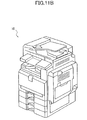
- FIG. 1 shows the exterior of an image forming device according to one embodiment of the present invention.
- An image forming device 10 includes a scanner 3 to read documents, an ADF (automatic document feeder) 1 to send documents to the scanner 3, a printer 5 to output read images of documents, a paper tray 6, and a paper discharge tray 4.
- ADF automatic document feeder
- the device body is comprised of the four-stage paper tray 6, printer 5 as image forming unit, scanner 3, and paper discharge tray 4 by way of example.
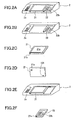
- FIGs. 2A to 2F show the division and detachment of the operation panel of the image forming device 10 in FIG. 1 .
- a panel unit 2 is dividable and includes an operation element 2a as keywswitches to decide an application such as copier, scanner, printer, and an LED in FIG. 2A .
- the operation element 2a is assumed to be not detached since the keywswitches and LED are not necessary for remote control in FIG. 2B .
- An operation panel 21 includes a display 21a as LCD, a touch panel for input to a display screen, and cameras 21b, 21c, an operation button 104 in FIG. 2C, 2D .
- a sub panel 22 includes ten keywswitches to input the number of copies, a start and stop button 22b to start and cancel copying or printing, an LED, and a camera 22a.
- the operation panel 21 and sub panel 22 are detachable from the device body and usable for a remote controller in FIGs. 2E, 2F .
- the operation panel 21 includes a controller 110 as CPU, a non-volatile second memory 112, a wired interface 113, a wireless interface 114, and a camera 21c.
- a control unit 200 of the device body includes a controller 210, a first storage 212, a wired interface 213, and a wireless interface 214.
- the control unit 200 and operation panel 21 when detached bidirectionally communicate with each other via the wired interfaces 113, 213 and wireless interfaces 114, 214.
- the first and second storages 112, 212 store image data to be displayed on the display 21a.
- FIG. 4A shows a normal screen on the display 21a in a standby mode when a user uses the image forming device 10 with the operation panel 21 mounted on the device body. While attached to the device body, the operation panel 21 does not display operation buttons since they are unnecessary.
- FIG. 5A shows a normal screen on the display 21a of the operation panel 21 detached when a user uses the image forming device 10 in a standby mode in FIG. 5B .
- the operation panel 21 When detached from the device body, the operation panel 21 shows the operation buttons. By a manipulation of these buttons on the operation panel 21, all the operations of the image forming device 10 can be performed.
- the functions of the operation element 2a and sub panel 22 are also displayed on the display 21a.
- FIG. 6A shows a document image preview on a full screen display of the display 21a of the operation panel 21
- FIG. 6B shows an enlarged document image preview on the display 21a
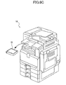
- FIG. 6C shows the operation panel 21 detached from the image forming device 10.
- the screen is switched to that in FIG. 6A from a standby display when a user intends to add a synthetic image on a read document or check the details of the document, for instance.
- FIG. 7A shows a camera image preview of a key 32 on a table 31 in FIG. 7B captured by a camera 21b of the operation panel 21.
- FIG. 7A omits showing a document image.
- edit mode a user can shoot a subject to synthesize while viewing the preview image.
- FIG. 8 shows a preview of a synthetic image of the camera image in FIG. 7A and a read document image on the display 21a of the operation panel 21.
- the preview image can be printed as it is or either or both of the camera image and document image can be modified as moved, enlarged, reduced, or partially extracted.
- FIGs. 9 to 10 show an example of moving image data from the camera. In FIG. 9 camera image data is being enlarged while in FIG. 10B a user is holding the operation panel 21 to manipulate the screen with her finger.
- FIG.10A shows that a user is operating the operation panel 21 in edit mode to move the key image rightward.
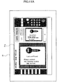
- FIG. 11A shows a printout image after the image synthesis and editing on a full screen display of the display 21a of the operation panel 21 detached from the image forming device in FIG. 11B .
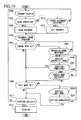
- FIG. 12 is an exemplary flowchart for the operation of the image forming device in FIG. 1 , using read document image data in FIGs. 14A to 14D .
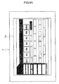
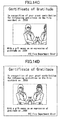
- FIG. 14A shows read document data on the display 21a
- FIG. 14 shows a set synthesis area at the center indicated by the broken line. The synthesis area can be set with a cursor or a touch panel.
- FIG. 14C shows adjusting the position of a subject by moving a block of the display 21a
- FIG. 14D shows a captured image in a desired position and a size.
- the controller 210 of the control unit 200 or that 110 of the operation panel 21 in FIG. 3 mainly performs the operation.
- step S100 the image forming device 10 starts operating in standby mode in FIGs. 4A , 5A .
- the controller 210 determines whether or not a reading operation has been instructed.
- the document reading is started by pressing a button 22a on the sub panel 22 in the standby mode in FIGs. 4A , 5B with the operation panel mounted on the device body while it is started by a button 21d on the display 21a of the operation panel 21 in FIGs. 5A , 5B with the operation panel detached.
- the operation panel 21 is detached, the operation is now taken over by the controller 110 in step S101.
- the controller 110 Upon determining that the instruction has not been issued yet (No in step S101), the controller 110 returns the standby display to the screen.
- the controller 110 proceeds to step S102.
- step S102 a document is read by the image forming device according to an instruction from the operation panel 21 to acquire image data.
- the controller 110 proceeds to step S103.
- step S103 a document image preview is displayed as shown in FIG. 6A .
- the preview image includes a blank space at the center for photographic data to be added.
- step S104 the controller 110 determines whether or not a camera mode is set. Upon determining that the camera mode is set (Yes in step S104), the controller 110 proceeds to step S105. Upon determining that the camera mode is not set (No in step S104), the controller 110 proceeds to step S109.
- the controller 110 determines whether or not the operation panel 21 is detached from the image forming device 10 in step S105. Upon determining that the operation panel 21 is attached to the image forming device 10 (No in step S105), the controller 110 returns to step S104. Upon determining that the operation panel 21 is detached (Yes in step S105), the controller 110 proceeds to step S106.
- the controller 110 instructs the display 21a to display a synthetic image of the document image and camera image as shown in FIGs. 8 , 9 , 10A .
- the controller 110 determines whether or not a subject has been shot by a user in step S107.
- the controller 110 acquires image data therefrom (Yes in step S107) and proceeds to step S109.
- the controller 110 proceeds to step S108.
- step S108 the controller 110 determines whether or not the camera mode is cancelled. That is, when the camera mode is cancelled before photographing (Yes in step S108), it proceeds to step S109. When the camera mode is continued (No in step S108), it returns to step S106.
- step S109 the controller 110 determines whether or not the edit mode is set. Upon determining that the edit mode is set (Yes in step S109), the controller 110 proceeds to step S110. Upon determining that the edit mode is not set (No in step S109), it proceeds to step S112.
- step S110 the controller 110 modifies image data according to a user's manipulation in FIG. 10B , displays the read document previews on the display 21a in FIGs. 10A , 11A , and proceeds to step S111.
- step S111 the controller 110 determines whether or not the editing has been completed. Upon determining the completion of editing (Yes in step S111), it proceeds to step S112 (No in step S111). Upon determining that editing is in progress, it returns to step S110.
- step S112 the controller 110 determines whether or not printing is instructed. With the printing instructed (Yes in step S112), the controller 110 gives a printing instruction to the controller 210 of the device body, and the controller 210 prints the image data in step S113. With no printing instructed (No in step S112), it cancels printing and returns to step S100.
- the synthesis area indicated by the broken line in FIG. 14B can be set in any stage after step S103 to photographing.
- FIG. 13 is a flowchart for another operation of the image forming device in FIG. 1 as an example of using pre-stored document image data.
- the steps S200 to S213 are the same as steps S100 to S113 except for step S201 so that a description thereof is omitted.
- step S201 the controller 110 determines whether or not a reading operation has been instructed. Upon determining that the reading operation has not been instructed (No in step S201), it determines whether or not stored document image data is selected in step S214. Upon determining that stored image data is not selected (No in step S214), it returns to step S200. Meanwhile, upon determining that stored image data is selected (Yes in step S214), it sets the selected image data in step S215 and proceeds to step S203.
- the image data shown in FIG. 14A or other similar image data be pre-stored and selected in step S214.
- the setting of the synthesis area in FIG. 14 can be registered in advance, which makes it possible to easily acquire the finished image data in FIG. 14D by only determining the image composition of the camera in FIG. 14C .
- a user can determine the position and size of a subject while viewing the display 21a and print out the image data without post-image processing.
- the subject is set not to be displayed outside the synthesis area during preview. Instead, it can be displayed outside the area during the preview but set not to be displayed after photographing. In either case the subject image data outside the synthesis area is not printed.
- the present embodiment allows a user to be able to freely move the position of a subject vertically, horizontally, and back and forth while viewing the preview display, to set subject image data in an arbitrary position and a desired size relative to document image data.
- This eliminates the necessity for post-image processing using image processing software with a mouse and a keyboard.
- a user can smoothly capture an image of a subject, create a synthetic image as shown in FIG. 11A and print it out at once.
- the present embodiment it is made possible to change the data size of a subject relative to that of a read document in accordance with a ratio of document data, a full screen data or a partially enlarged data in FIGs. 8 , 9 , on the display.
- Subject image data can be enlarged at the same ratio along with the enlargement of the document data during preview or in post-photographing adjustment.
- a plurality of synthesis areas can be set in different colors or with different brightness.
- the cameras as imaging element can comprise a moving image shooting function in addition to a still image shooting function.
- the image forming device can select optimal subject image data relative to document image data in a certain shooting time. Further, it can comprise an image data corrector to correct synthesized image data by adjusting at least one of the position, size, rotation, color, and brightness of the subject image data relative to the document image data.
- the communication element can be a wireless communication and it can be configured that synthetic image data can be printed from the printer without the operation panel mounted on the device body.
- the operation panel can be configured to operate all or a part of the functions of the image forming device.
Landscapes
- Physics & Mathematics (AREA)
- General Physics & Mathematics (AREA)
- Engineering & Computer Science (AREA)
- Microelectronics & Electronic Packaging (AREA)
- Facsimiles In General (AREA)
- Editing Of Facsimile Originals (AREA)
- Accessory Devices And Overall Control Thereof (AREA)
- Record Information Processing For Printing (AREA)
- Control Or Security For Electrophotography (AREA)
Abstract
Description
- The present invention relates to an image forming device incorporating an operation panel detachable from a device body and an image forming method.
- Japanese Patent No.
4387961 - This operation panel comprises operation blocks provided in the device body and having items to select in accordance with the functions of the device and a data output to output selection data indicating the selected items with the operation blocks to the device. The operation panel further includes a detachable display block having a display to display the items to select the device functions, a detector to detect an item selected, a controller to control the display to display the items to select together with the items of the other operation blocks when detached and a data acquiring element to acquire the selected item by the detector as the selection data from the detached display block. The data output is adapted to output the acquired selection data to the device.
- By manipulation of this operation panel detached, the image forming device can be operated. However, only simple operations such as power-on/off, print start and stop are feasible.
- The present invention aims to provide image forming device and method with a detachable operation panel including photographic and display functions to be able to smoothly complete printing by a simple operation after setting an image composition on a display.
- An image forming device comprises a device body including a reader to read a document and a printer to print the read document, an operation panel detachable from the device body, including an imaging element to capture an image of a subject and a display unit, a communication element to communicably connect the device body and the operation panel, wherein the image forming device is adapted to synthesize document image data read by the reader and subject image data captured by the imaging element, display the synthesized image data on the display unit, and print the synthesized image data with the printer, while the operation panel is detached from the device body.
- Features, embodiments, and advantages of the present invention will become apparent from the following detailed description with reference to the accompanying drawings:
-
FIG. 1 schematically shows the exterior of an image forming device according to one embodiment of the present invention; -
FIGs. 2A to 2F show an operation panel divided and detached; -
FIG. 3 is a block diagram of a device body and the operation panel by way of example; -
FIG. 4A shows an operation panel in a standby mode mounted in the device body andFIG. 4B is a perspective view of the exterior of the image forming device; -
FIG. 5A shows the operation panel in a standby mode detached from the device body andFIG. 5B is a perspective view of the image forming device inFIG. 4B with the operation panel detached; -
FIG. 6A is a document preview on a full screen display of the operation panel detached from the device body,Fig. 6B an enlarged document preview on the operation panel, andFIG. 6C is a perspective view of the image forming device inFIG. 4B with the operation panel detached; -
FIG. 7A shows a camera image preview on the operation panel detached from the device body andFIG. 7B is a perspective view of the image forming device with the operation panel detached to shoot a key on the table; -
FIG. 8 shows the synthetic image of a document image and a camera image on a full screen display of the detached operation panel before the adjustment of a synthesis position; -
FIG. 9 shows an enlarged synthetic image of a document image and a camera image on the detached operation panel before the adjustment of a synthesis position; -
FIG. 10A shows editing an enlarged synthetic image of a document image and camera image on the detached operation panel after the adjustment of the synthesis position andFIG 10B shows a user's operating the operation panel; -
FIG. 11A shows the document image preview on a full screen display of the detached operation panel while printed after completion of the synthesis andFIG. 11B is a perspective view of the exterior of the image forming device with the operation panel detached; -
FIG. 12 is a flowchart for the operation of the image forming device inFIG. 1 ; -
FIG. 13 is a flowchart for another operation of the image forming device inFIG. 1 ; and -
FIGs. 14A to 14D show an example of read document image data, a synthesis area set indicated by the broken line, moving a block of thedisplay 21a to adjust the position of a subject, and the image data set in a desired position and size, respectively. - The features of the present embodiment are in accurately deciding the position and size of image data of a subject relative to document image data at photographing, to thereby eliminate the necessity for post-image processing such as position adjustment or enlargement and reduction. The post-image processing is preferably performed at a later opportunity. It is able to facilitate alteration to image data by synthesizing camera image data and image data read from the image forming device for output.
- Hereinafter, one embodiment of the present invention will be described in detail with reference to
FIG. 1 to FIG. 14 . Wherever possible, the same reference numbers will be used throughout the drawings to refer to the same or like parts. -
FIG. 1 shows the exterior of an image forming device according to one embodiment of the present invention. Animage forming device 10 includes ascanner 3 to read documents, an ADF (automatic document feeder) 1 to send documents to thescanner 3, aprinter 5 to output read images of documents, apaper tray 6, and apaper discharge tray 4. - From the bottom in the drawing, the device body is comprised of the four-
stage paper tray 6,printer 5 as image forming unit,scanner 3, andpaper discharge tray 4 by way of example. -
FIGs. 2A to 2F show the division and detachment of the operation panel of theimage forming device 10 inFIG. 1 . Apanel unit 2 is dividable and includes anoperation element 2a as keywswitches to decide an application such as copier, scanner, printer, and an LED inFIG. 2A . Theoperation element 2a is assumed to be not detached since the keywswitches and LED are not necessary for remote control inFIG. 2B . - An
operation panel 21 includes adisplay 21a as LCD, a touch panel for input to a display screen, andcameras operation button 104 inFIG. 2C, 2D . - A
sub panel 22 includes ten keywswitches to input the number of copies, a start andstop button 22b to start and cancel copying or printing, an LED, and acamera 22a. - The
operation panel 21 andsub panel 22 are detachable from the device body and usable for a remote controller inFIGs. 2E, 2F . - Next, referring to
FIG. 5 , the structure of the essential parts of the device body and the operation panel is described by way of example. Theoperation panel 21 includes acontroller 110 as CPU, a non-volatilesecond memory 112, awired interface 113, awireless interface 114, and acamera 21c. Likewise, acontrol unit 200 of the device body includes acontroller 210, afirst storage 212, awired interface 213, and awireless interface 214. - The
control unit 200 andoperation panel 21 when detached bidirectionally communicate with each other via thewired interfaces wireless interfaces second storages display 21a. - Referring to
FIGs, 4 to 8 , an example of the image synthesis and printout of the operation panel detached from the image forming device is described.FIG. 4A shows a normal screen on thedisplay 21a in a standby mode when a user uses theimage forming device 10 with theoperation panel 21 mounted on the device body. While attached to the device body, theoperation panel 21 does not display operation buttons since they are unnecessary. -
FIG. 5A shows a normal screen on thedisplay 21a of theoperation panel 21 detached when a user uses theimage forming device 10 in a standby mode inFIG. 5B . When detached from the device body, theoperation panel 21 shows the operation buttons. By a manipulation of these buttons on theoperation panel 21, all the operations of theimage forming device 10 can be performed. The functions of theoperation element 2a andsub panel 22 are also displayed on thedisplay 21a. -
FIG. 6A shows a document image preview on a full screen display of thedisplay 21a of theoperation panel 21,FIG. 6B shows an enlarged document image preview on thedisplay 21a andFIG. 6C shows theoperation panel 21 detached from theimage forming device 10. - The screen is switched to that in
FIG. 6A from a standby display when a user intends to add a synthetic image on a read document or check the details of the document, for instance. -
FIG. 7A shows a camera image preview of a key 32 on a table 31 inFIG. 7B captured by acamera 21b of theoperation panel 21.FIG. 7A omits showing a document image. In edit mode a user can shoot a subject to synthesize while viewing the preview image. -
FIG. 8 shows a preview of a synthetic image of the camera image inFIG. 7A and a read document image on thedisplay 21a of theoperation panel 21. The preview image can be printed as it is or either or both of the camera image and document image can be modified as moved, enlarged, reduced, or partially extracted.FIGs. 9 to 10 show an example of moving image data from the camera. InFIG. 9 camera image data is being enlarged while inFIG. 10B a user is holding theoperation panel 21 to manipulate the screen with her finger.FIG.10A shows that a user is operating theoperation panel 21 in edit mode to move the key image rightward. -
FIG. 11A shows a printout image after the image synthesis and editing on a full screen display of thedisplay 21a of theoperation panel 21 detached from the image forming device inFIG. 11B . -
FIG. 12 is an exemplary flowchart for the operation of the image forming device inFIG. 1 , using read document image data inFIGs. 14A to 14D .FIG. 14A shows read document data on thedisplay 21a,FIG. 14 shows a set synthesis area at the center indicated by the broken line. The synthesis area can be set with a cursor or a touch panel.FIG. 14C shows adjusting the position of a subject by moving a block of thedisplay 21a andFIG. 14D shows a captured image in a desired position and a size. - The
controller 210 of thecontrol unit 200 or that 110 of theoperation panel 21 inFIG. 3 mainly performs the operation. In step S100 theimage forming device 10 starts operating in standby mode inFIGs. 4A ,5A . - The
controller 210 determines whether or not a reading operation has been instructed. The document reading is started by pressing abutton 22a on thesub panel 22 in the standby mode inFIGs. 4A ,5B with the operation panel mounted on the device body while it is started by abutton 21d on thedisplay 21a of theoperation panel 21 inFIGs. 5A ,5B with the operation panel detached. When theoperation panel 21 is detached, the operation is now taken over by thecontroller 110 in step S101. Upon determining that the instruction has not been issued yet (No in step S101), thecontroller 110 returns the standby display to the screen. Upon determining that the instruction has been issued (Yes in step S101), thecontroller 110 proceeds to step S102. - In step S102 a document is read by the image forming device according to an instruction from the
operation panel 21 to acquire image data. Thecontroller 110 proceeds to step S103. - In step S103 a document image preview is displayed as shown in
FIG. 6A . InFIG. 14A the preview image includes a blank space at the center for photographic data to be added. - In step S104 the
controller 110 determines whether or not a camera mode is set. Upon determining that the camera mode is set (Yes in step S104), thecontroller 110 proceeds to step S105. Upon determining that the camera mode is not set (No in step S104), thecontroller 110 proceeds to step S109. - The
controller 110 determines whether or not theoperation panel 21 is detached from theimage forming device 10 in step S105. Upon determining that theoperation panel 21 is attached to the image forming device 10 (No in step S105), thecontroller 110 returns to step S104. Upon determining that theoperation panel 21 is detached (Yes in step S105), thecontroller 110 proceeds to step S106. - The
controller 110 instructs thedisplay 21a to display a synthetic image of the document image and camera image as shown inFIGs. 8 ,9 ,10A . - The
controller 110 determines whether or not a subject has been shot by a user in step S107. When the user has captured a subject image, thecontroller 110 acquires image data therefrom (Yes in step S107) and proceeds to step S109. When the subject has not been shot (No in step S107), that is, the user is setting the composition of an image, thecontroller 110 proceeds to step S108. - In step S108 the
controller 110 determines whether or not the camera mode is cancelled. That is, when the camera mode is cancelled before photographing (Yes in step S108), it proceeds to step S109. When the camera mode is continued (No in step S108), it returns to step S106. - In step S109 the
controller 110 determines whether or not the edit mode is set. Upon determining that the edit mode is set (Yes in step S109), thecontroller 110 proceeds to step S110. Upon determining that the edit mode is not set (No in step S109), it proceeds to step S112. - In step S110 the
controller 110 modifies image data according to a user's manipulation inFIG. 10B , displays the read document previews on thedisplay 21a inFIGs. 10A ,11A , and proceeds to step S111. - In step S111 the
controller 110 determines whether or not the editing has been completed. Upon determining the completion of editing (Yes in step S111), it proceeds to step S112 (No in step S111). Upon determining that editing is in progress, it returns to step S110. - In step S112 the
controller 110 determines whether or not printing is instructed. With the printing instructed (Yes in step S112), thecontroller 110 gives a printing instruction to thecontroller 210 of the device body, and thecontroller 210 prints the image data in step S113. With no printing instructed (No in step S112), it cancels printing and returns to step S100. - The synthesis area indicated by the broken line in
FIG. 14B can be set in any stage after step S103 to photographing. -
FIG. 13 is a flowchart for another operation of the image forming device inFIG. 1 as an example of using pre-stored document image data. The steps S200 to S213 are the same as steps S100 to S113 except for step S201 so that a description thereof is omitted. - In step S201 the
controller 110 determines whether or not a reading operation has been instructed. Upon determining that the reading operation has not been instructed (No in step S201), it determines whether or not stored document image data is selected in step S214. Upon determining that stored image data is not selected (No in step S214), it returns to step S200. Meanwhile, upon determining that stored image data is selected (Yes in step S214), it sets the selected image data in step S215 and proceeds to step S203. - It is preferable that the image data shown in
FIG. 14A or other similar image data be pre-stored and selected in step S214. In addition, the setting of the synthesis area inFIG. 14 can be registered in advance, which makes it possible to easily acquire the finished image data inFIG. 14D by only determining the image composition of the camera inFIG. 14C . - Thus, a user can determine the position and size of a subject while viewing the
display 21a and print out the image data without post-image processing. InFIG. 14C the subject is set not to be displayed outside the synthesis area during preview. Instead, it can be displayed outside the area during the preview but set not to be displayed after photographing. In either case the subject image data outside the synthesis area is not printed. - As described above, the present embodiment allows a user to be able to freely move the position of a subject vertically, horizontally, and back and forth while viewing the preview display, to set subject image data in an arbitrary position and a desired size relative to document image data. This eliminates the necessity for post-image processing using image processing software with a mouse and a keyboard. A user can smoothly capture an image of a subject, create a synthetic image as shown in
FIG. 11A and print it out at once. - According to the present embodiment, it is made possible to change the data size of a subject relative to that of a read document in accordance with a ratio of document data, a full screen data or a partially enlarged data in
FIGs. 8 ,9 , on the display. Subject image data can be enlarged at the same ratio along with the enlargement of the document data during preview or in post-photographing adjustment. - Further, a plurality of synthesis areas can be set in different colors or with different brightness.
- The cameras as imaging element can comprise a moving image shooting function in addition to a still image shooting function. The image forming device can select optimal subject image data relative to document image data in a certain shooting time. Further, it can comprise an image data corrector to correct synthesized image data by adjusting at least one of the position, size, rotation, color, and brightness of the subject image data relative to the document image data.
- Further, the communication element can be a wireless communication and it can be configured that synthetic image data can be printed from the printer without the operation panel mounted on the device body.
- Further, the operation panel can be configured to operate all or a part of the functions of the image forming device.
- Although the present invention has been described in terms of exemplary embodiments, it is not limited thereto. It should be appreciated that variations or modifications may be made in the embodiments described by persons skilled in the art without departing from the scope of the present invention as defined by the following claims. The above embodiment describes a certificate of gratitude by way of example, however, it can be applied in various occasions as ceremonies, parties.
Claims (10)
- An image forming device (10) comprising:a device body including a reader (3) to read a document and a printer (5) to print the read document;an operation panel (21) detachable from the device body, including an imaging element (21b, 21c) to capture an image of a subject and a display unit (21a);a communication element (113, 213, 114, 214) to communicably connect the device body and the operation panel (21), whereinthe image forming device (10) is adapted to synthesize document image data read by the reader (3) and subject image data captured by the imaging element (21b, 21c), display the synthesized image data on the display unit (21a), and print the synthesized image data with the printer (5), while the operation panel (21) is detached from the device body.
- An image forming device according to claim 1, wherein
the display unit (21a) is adapted to display a preview image of the imaging element together with the read document image data while the operation panel (21) is detached from the device body. - An image forming device (10) according to either claim 1 or 2, wherein
the synthesize image data is reduced or enlarged in size on the display unit at a same ratio of the subject image data and document image data and printed at the same ratio from the printer. - An image forming device (10) according to any one of claims 1 to 3, further comprising:a synthesis area setter to set, on the display unit (21a), an area in which the document image data is synthesized with the subject image data, while the document image data is being displayed on the display unit and while the operation panel is detached from the device body.
- An image forming device (10) according to claim 4, wherein:the synthesis area setter is adapted to set a plurality of areas; andthe image forming device (10) is adapted to display the areas on the display unit and acquire subject image data of the areas individually while the operation panel is detached from the device body.
- An image forming device (10) according to any one of claims 1 to 5, further comprising
an image data corrector to correct the synthesized image data after the subject image data is acquired, by adjusting at least one of a position, a size, a rotation, a color, and brightness of the subject image data relative to the document image data. - An image forming device (10) according to any one of claims 1 to 6, wherein:the imaging element (21b, 21 c) comprises still image and moving image shooting functions and a moving image selecting function to select subject image data in a certain shooting time when moving image data is acquired by the moving image shooting; andthe image forming device is adapted to synthesize the selected moving image data of the subject with the document image data and print the synthesized image data with the printer.
- An image forming device (10) according to any one of claims 1 to 7, wherein
the communication element (113, 213, 114, 214) is a wireless communication, to allow the printer (5) to print the synthesized image data without the operation panel attached to the device body. - An image forming device (10) according to any one of claims 1 to 8, wherein
the operation panel is configured to operate at least a part of the functions of the device body. - An image forming method by use of a detachable operation panel (21), comprising the steps of:reading image data of a document;displaying a camera preview image together with read document image data on the operation panel detached;synthesizing image data of a subject and the document image data; andprinting the synthesized image data.
Applications Claiming Priority (1)
| Application Number | Priority Date | Filing Date | Title |
|---|---|---|---|
| JP2012042070A JP2013179463A (en) | 2012-02-28 | 2012-02-28 | Image forming device and image forming method |
Publications (2)
| Publication Number | Publication Date |
|---|---|
| EP2634644A2 true EP2634644A2 (en) | 2013-09-04 |
| EP2634644A3 EP2634644A3 (en) | 2017-11-08 |
Family
ID=47912920
Family Applications (1)
| Application Number | Title | Priority Date | Filing Date |
|---|---|---|---|
| EP13157156.4A Withdrawn EP2634644A3 (en) | 2012-02-28 | 2013-02-28 | Image forming device and method |
Country Status (2)
| Country | Link |
|---|---|
| EP (1) | EP2634644A3 (en) |
| JP (1) | JP2013179463A (en) |
Cited By (1)
| Publication number | Priority date | Publication date | Assignee | Title |
|---|---|---|---|---|
| EP4141570A1 (en) * | 2021-08-20 | 2023-03-01 | Toshiba TEC Kabushiki Kaisha | Image forming device and control method |
Citations (1)
| Publication number | Priority date | Publication date | Assignee | Title |
|---|---|---|---|---|
| JP4387961B2 (en) | 2005-02-16 | 2009-12-24 | 株式会社リコー | Operation panel and image forming apparatus |
Family Cites Families (7)
| Publication number | Priority date | Publication date | Assignee | Title |
|---|---|---|---|---|
| JPH08314329A (en) * | 1995-05-18 | 1996-11-29 | Ricoh Co Ltd | Color image forming device |
| JP2005028729A (en) * | 2003-07-11 | 2005-02-03 | Seiko Epson Corp | Printing device, portable terminal unit provided in printing device, printer device unit provided in printing device, and printing method |
| JP2005086385A (en) * | 2003-09-08 | 2005-03-31 | Konica Minolta Business Technologies Inc | Image forming apparatus |
| JP2006101412A (en) * | 2004-09-30 | 2006-04-13 | Seiko Epson Corp | Compound machine |
| JP4678857B2 (en) * | 2005-12-28 | 2011-04-27 | キヤノン株式会社 | Image processing apparatus, image processing method, and program |
| US8085242B2 (en) * | 2007-09-10 | 2011-12-27 | Ricoh Company, Ltd. | Input control device and image forming apparatus |
| JP2012029164A (en) * | 2010-07-26 | 2012-02-09 | Konica Minolta Business Technologies Inc | Portable terminal and device managing method |
-
2012
- 2012-02-28 JP JP2012042070A patent/JP2013179463A/en active Pending
-
2013
- 2013-02-28 EP EP13157156.4A patent/EP2634644A3/en not_active Withdrawn
Patent Citations (1)
| Publication number | Priority date | Publication date | Assignee | Title |
|---|---|---|---|---|
| JP4387961B2 (en) | 2005-02-16 | 2009-12-24 | 株式会社リコー | Operation panel and image forming apparatus |
Cited By (1)
| Publication number | Priority date | Publication date | Assignee | Title |
|---|---|---|---|---|
| EP4141570A1 (en) * | 2021-08-20 | 2023-03-01 | Toshiba TEC Kabushiki Kaisha | Image forming device and control method |
Also Published As
| Publication number | Publication date |
|---|---|
| JP2013179463A (en) | 2013-09-09 |
| EP2634644A3 (en) | 2017-11-08 |
Similar Documents
| Publication | Publication Date | Title |
|---|---|---|
| EP1156453B1 (en) | Image processing apparatus, image processing method, storage medium, and program | |
| JP7663908B2 (en) | Operation system and operation method | |
| CN113632056A (en) | Operating device and display control program | |
| JP5544736B2 (en) | Image processing apparatus and image processing program | |
| JP6627448B2 (en) | Print production equipment | |
| JP2005303800A (en) | Photographing apparatus | |
| JP3927453B2 (en) | Automatic photo creation method and automatic photo creation device | |
| JP2006172021A (en) | Image processing apparatus and image processing method | |
| JP2006050064A (en) | Method and apparatus of photographing editing | |
| JP2013179463A (en) | Image forming device and image forming method | |
| JP5800270B1 (en) | Photography game machine and its control program | |
| JP3524088B1 (en) | Image input method, image input program, and photo vending machine | |
| JP5119642B2 (en) | Automatic photo creation device and automatic photo creation method | |
| JP2005229355A (en) | Photograph vending machine, and control method and control program thereof | |
| US7812977B2 (en) | Image-processing system, image-processing method, and product of image-processing program for displaying an image individually or as a composite image | |
| JP4671804B2 (en) | Image forming apparatus | |
| JP2005086385A (en) | Image forming apparatus | |
| JP4438888B2 (en) | Image forming apparatus | |
| JP2006080978A (en) | Photography system | |
| JP2008210347A (en) | Image editing device, method, and program | |
| JP2002152668A (en) | Multi-display apparatus, multi-display method, photographing system and photographing method | |
| JP2025012676A (en) | Information processing system and information processing method | |
| JP2015146531A (en) | Game-oriented imaging apparatus, image processing method and program | |
| JP2001133912A (en) | Photo processing equipment | |
| JP2010239340A (en) | Mobile terminal, computer program for controlling mobile terminal, and recording medium recording the program |
Legal Events
| Date | Code | Title | Description |
|---|---|---|---|
| PUAI | Public reference made under article 153(3) epc to a published international application that has entered the european phase |
Free format text: ORIGINAL CODE: 0009012 |
|
| 17P | Request for examination filed |
Effective date: 20130228 |
|
| AK | Designated contracting states |
Kind code of ref document: A2 Designated state(s): AL AT BE BG CH CY CZ DE DK EE ES FI FR GB GR HR HU IE IS IT LI LT LU LV MC MK MT NL NO PL PT RO RS SE SI SK SM TR |
|
| AX | Request for extension of the european patent |
Extension state: BA ME |
|
| PUAL | Search report despatched |
Free format text: ORIGINAL CODE: 0009013 |
|
| AK | Designated contracting states |
Kind code of ref document: A3 Designated state(s): AL AT BE BG CH CY CZ DE DK EE ES FI FR GB GR HR HU IE IS IT LI LT LU LV MC MK MT NL NO PL PT RO RS SE SI SK SM TR |
|
| AX | Request for extension of the european patent |
Extension state: BA ME |
|
| RIC1 | Information provided on ipc code assigned before grant |
Ipc: G03G 15/36 20060101AFI20170929BHEP Ipc: G03G 15/00 20060101ALI20170929BHEP |
|
| STAA | Information on the status of an ep patent application or granted ep patent |
Free format text: STATUS: THE APPLICATION HAS BEEN WITHDRAWN |
|
| 18W | Application withdrawn |
Effective date: 20200428 |