EP2634643A2 - Fixing device, image forming apparatus including the same, and method for controlling the fixing device - Google Patents
Fixing device, image forming apparatus including the same, and method for controlling the fixing device Download PDFInfo
- Publication number
- EP2634643A2 EP2634643A2 EP13156809.9A EP13156809A EP2634643A2 EP 2634643 A2 EP2634643 A2 EP 2634643A2 EP 13156809 A EP13156809 A EP 13156809A EP 2634643 A2 EP2634643 A2 EP 2634643A2
- Authority
- EP
- European Patent Office
- Prior art keywords
- rotating member
- motor
- moved
- signal line
- transistor
- Prior art date
- Legal status (The legal status is an assumption and is not a legal conclusion. Google has not performed a legal analysis and makes no representation as to the accuracy of the status listed.)
- Granted
Links
- 238000000034 method Methods 0.000 title claims description 20
- 238000003825 pressing Methods 0.000 claims abstract description 112
- 238000010438 heat treatment Methods 0.000 claims abstract description 82
- 230000007246 mechanism Effects 0.000 claims abstract description 45
- 230000003247 decreasing effect Effects 0.000 claims description 25
- 230000002401 inhibitory effect Effects 0.000 claims description 3
- 238000010586 diagram Methods 0.000 description 26
- 238000001514 detection method Methods 0.000 description 23
- 230000032258 transport Effects 0.000 description 20
- 230000009471 action Effects 0.000 description 15
- 108091008695 photoreceptors Proteins 0.000 description 12
- 238000012545 processing Methods 0.000 description 10
- 230000008569 process Effects 0.000 description 9
- 229910052751 metal Inorganic materials 0.000 description 8
- 239000002184 metal Substances 0.000 description 8
- 238000004891 communication Methods 0.000 description 6
- 230000007423 decrease Effects 0.000 description 6
- 238000012546 transfer Methods 0.000 description 6
- 230000015556 catabolic process Effects 0.000 description 5
- 239000003990 capacitor Substances 0.000 description 4
- 238000003860 storage Methods 0.000 description 4
- 238000006243 chemical reaction Methods 0.000 description 3
- 230000003287 optical effect Effects 0.000 description 3
- 230000002829 reductive effect Effects 0.000 description 3
- 230000001052 transient effect Effects 0.000 description 3
- XEEYBQQBJWHFJM-UHFFFAOYSA-N Iron Chemical compound [Fe] XEEYBQQBJWHFJM-UHFFFAOYSA-N 0.000 description 2
- 230000005540 biological transmission Effects 0.000 description 2
- 238000004140 cleaning Methods 0.000 description 2
- 238000011144 upstream manufacturing Methods 0.000 description 2
- 208000033748 Device issues Diseases 0.000 description 1
- XUIMIQQOPSSXEZ-UHFFFAOYSA-N Silicon Chemical compound [Si] XUIMIQQOPSSXEZ-UHFFFAOYSA-N 0.000 description 1
- 230000002159 abnormal effect Effects 0.000 description 1
- 230000001133 acceleration Effects 0.000 description 1
- 229910052782 aluminium Inorganic materials 0.000 description 1
- XAGFODPZIPBFFR-UHFFFAOYSA-N aluminium Chemical compound [Al] XAGFODPZIPBFFR-UHFFFAOYSA-N 0.000 description 1
- 230000008859 change Effects 0.000 description 1
- 238000007796 conventional method Methods 0.000 description 1
- 238000005485 electric heating Methods 0.000 description 1
- 238000009499 grossing Methods 0.000 description 1
- 229910052736 halogen Inorganic materials 0.000 description 1
- 150000002367 halogens Chemical class 0.000 description 1
- 230000006698 induction Effects 0.000 description 1
- 229910052742 iron Inorganic materials 0.000 description 1
- 239000004973 liquid crystal related substance Substances 0.000 description 1
- 238000004519 manufacturing process Methods 0.000 description 1
- 238000012986 modification Methods 0.000 description 1
- 230000004048 modification Effects 0.000 description 1
- 230000002093 peripheral effect Effects 0.000 description 1
- 230000009467 reduction Effects 0.000 description 1
- 239000011347 resin Substances 0.000 description 1
- 229920005989 resin Polymers 0.000 description 1
- 230000002441 reversible effect Effects 0.000 description 1
- 229910052710 silicon Inorganic materials 0.000 description 1
- 239000010703 silicon Substances 0.000 description 1
- 239000000758 substrate Substances 0.000 description 1
- 238000010792 warming Methods 0.000 description 1
Images




Classifications
-
- G—PHYSICS
- G03—PHOTOGRAPHY; CINEMATOGRAPHY; ANALOGOUS TECHNIQUES USING WAVES OTHER THAN OPTICAL WAVES; ELECTROGRAPHY; HOLOGRAPHY
- G03G—ELECTROGRAPHY; ELECTROPHOTOGRAPHY; MAGNETOGRAPHY
- G03G15/00—Apparatus for electrographic processes using a charge pattern
- G03G15/20—Apparatus for electrographic processes using a charge pattern for fixing, e.g. by using heat
- G03G15/2003—Apparatus for electrographic processes using a charge pattern for fixing, e.g. by using heat using heat
- G03G15/2014—Apparatus for electrographic processes using a charge pattern for fixing, e.g. by using heat using heat using contact heat
- G03G15/2039—Apparatus for electrographic processes using a charge pattern for fixing, e.g. by using heat using heat using contact heat with means for controlling the fixing temperature
-
- G—PHYSICS
- G03—PHOTOGRAPHY; CINEMATOGRAPHY; ANALOGOUS TECHNIQUES USING WAVES OTHER THAN OPTICAL WAVES; ELECTROGRAPHY; HOLOGRAPHY
- G03G—ELECTROGRAPHY; ELECTROPHOTOGRAPHY; MAGNETOGRAPHY
- G03G15/00—Apparatus for electrographic processes using a charge pattern
- G03G15/20—Apparatus for electrographic processes using a charge pattern for fixing, e.g. by using heat
- G03G15/2003—Apparatus for electrographic processes using a charge pattern for fixing, e.g. by using heat using heat
- G03G15/2014—Apparatus for electrographic processes using a charge pattern for fixing, e.g. by using heat using heat using contact heat
- G03G15/2017—Structural details of the fixing unit in general, e.g. cooling means, heat shielding means
- G03G15/2032—Retractable heating or pressure unit
- G03G15/2035—Retractable heating or pressure unit for maintenance purposes, e.g. for removing a jammed sheet
Definitions
- the present disclosure relates to a fixing device for fixing toner, an image forming apparatus including the fixing device, and a method for controlling the fixing device.
- An image forming apparatus such as a copier, a multifunction peripheral, a printer, or a facsimile apparatus is equipped with a plurality of motors for driving rotating members to rotate, which includes various rollers and a photoreceptor drum. Further, conventionally, it is common to perform rotation control (operational control) of the motors by software control using a control device (processor) such as a CPU or a microcomputer. However, if runaway of a control device occurs, excessive force may be applied to a motor, a transmission portion for transmitting motor power, or a portion driven by the motor power, resulting in a breakdown. Therefore, there is known a technique to prevent runaway of a carriage (head moving portion of an ink jet printer apparatus) due to runaway of the CPU.
- a control device such as a CPU or a microcomputer.
- a carriage drive control device for a carriage drive motor for driving the carriage to move in a printer, which includes a pulse signal output unit that outputs a pulse signal whose number of pulses is proportional to a movement amount of the carriage, a control unit that output a control signal for controlling the carriage drive motor by feedback control using the pulse signal received from the pulse signal output unit so as to make a predetermined speed pattern including acceleration, constant speed, and deceleration, a carriage driving circuit that drives the carriage drive motor on the basis of the control signal received from the control unit, and a pulse period detection circuit constituted of a hardware logic circuit that detects a pulse period of the pulse signal received from the pulse signal output unit and compares the detected pulse period with a lower limit value having a predetermined set pulse period, so as to output a stop instruction signal for instructing the carriage driving circuit to forcedly stop the carriage drive motor when the detected pulse period becomes smaller than the lower limit value.
- an electrophotography type image forming apparatus is equipped with a fixing device for fixing a toner image transferred onto a paper sheet.
- the fixing device includes a heating rotating member (for example, a roller) which is heated by a heat generating member so as to heat toner, and a pressing rotating member (for example, a roller) which is pressed to the heating rotating member.
- a paper sheet onto which a toner image is transferred is permitted to pass through a nip between the heating rotating member and the pressing rotating member, and hence the fixing process is performed.
- the fixing device may include a mechanism for decreasing fixing pressure by separating the heating rotating member from the pressing rotating member during interval between printing processes, while permitting the heating rotating member and the pressing rotating member to be close to each other for making a pressed state (contact state) with pressure (fixing pressure) of the nip in the printing process.
- a motor may be used as a drive source for moving the rotating member.
- a sensor for detecting a position of the rotating member or a rotation angle of the motor is disposed so that a control device such as a CPU for controlling rotation of the motor receives an output of the sensor, the control device recognizes a position of the rotating member or a state of the motor, and hence a rotation direction, a rotation angle, and stop of the motor are controlled by software control.
- the control device such as the CPU runs away, the motor drive is continued (locked state is continued) even if the rotating member becomes a limit position. Therefore, the motor or a component such as a gear included in the mechanism for moving the rotating member may be broken down.
- a CPU port for receiving the output of the sensor may be lacking, or wiring may be complicated.
- the above-mentioned known carriage drive control device is a device related to movement of the carriage and is not related to adjustment of the fixing pressure of the fixing device.
- the device cannot be used without a thing for generating a pulse in accordance with motor rotation (for example, an encoder).
- a high accuracy encoder is expensive, and hence there is a demerit that manufacturing cost increases.
- the present disclosure is made in view of the above-mentioned problems of the conventional technique, and it is an object thereof to cancel the demerit due to the structure in which the control device such as the CPU performs software control, in which the output of the sensor is supplied to a stop control circuit for controlling to stop the motor as hardware, instead that the control device such as the CPU controls to stop the motor by software control like the conventional structure, so as to safely stop the motor even if the control device such as the CPU runs away.
- a fixing device includes a heating rotating member, a pressing rotating member, a motor, a fixing pressure adjustment mechanism, a control section, a motor drive section, a detecting member, and a stop control circuit.
- the heating rotating member heats the paper sheet onto which toner is transferred.
- the pressing rotating member is pressed to the heating rotating member so as to form a nip.
- the motor can rotate in both forward and backward directions.
- the fixing pressure adjustment mechanism is driven by the motor so as to move a rotating member to be moved that is one of the pressing rotating member and the heating rotating member, in accordance with a rotation direction of the motor between predetermined first and second positions in a pressure increasing direction or in a pressure decreasing direction, and hence a fixing pressure that is a pressure of the nip is adjusted.
- the control section includes a control device, which issues an instruction of voltage to be applied to the motor in accordance with the rotation direction of the motor by software control.
- the motor drive section controls the voltage to be applied to the motor on the basis of the instruction from the control section.
- the detecting member detects that the rotating member to be moved that has been moved by the fixing pressure adjustment mechanism reaches a first position so that the control device does not receive the output.
- the stop control circuit receives an output of the detecting member and stops the motor without software control when the detecting member detects that the rotating member to be moved reaches the first position.
- a method for controlling a fixing device includes the steps of permitting the heating rotating member to heat a paper sheet onto which toner is transferred, pressing a pressing rotating member to the heating rotating member so as to form a nip, moving a rotating member to be moved that is one of the heating rotating member and the pressing rotating member, between predetermined first and second positions in a pressure increasing direction and in a pressure decreasing direction, on the basis of driving a motor that can rotate in forward and backward directions, in accordance with a rotation direction of the motor, so as to permit the fixing pressure adjustment mechanism to adjust a fixing pressure that is a pressure of the nip, permitting a control section including a control device to issue an instruction of a voltage to be applied to the motor by software control in accordance with the rotation direction of the motor, permitting the motor drive section to control the voltage to be applied to the motor on the basis of the instruction from the control section, inhibiting an output of a detecting member for
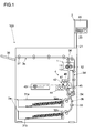
- FIG. 1 is a schematic cross-sectional front view illustrating an outline structure of a printer.
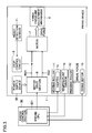
- FIG. 2 is a block diagram illustrating an example of a hardware structure of the printer.
- FIG. 3 is a block diagram illustrating an example of a fixing device.
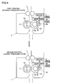
- FIG. 4 is an explanatory diagram illustrating an example of a fixing pressure adjustment mechanism.
- FIG. 5 is an explanatory diagram illustrating an example of a sensor for detecting that a first position (highest pressure position) is reached.
- FIG. 6 is an explanatory diagram illustrating an example of a worm gear included in a gear train of the fixing pressure adjustment mechanism.
- FIG. 7 is an explanatory diagram illustrating an example of a tooth-lacking gear.
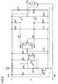
- FIG. 8 is a circuit diagram illustrating an example of a stop control circuit.
- FIG. 9 is a flowchart illustrating an example of a flow of fixing pressure adjustment.
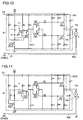
- FIG. 10 is a circuit diagram for describing an action of the stop control circuit during increasing the fixing pressure.
- FIG. 11 is a circuit diagram for describing an action of the stop control circuit in a highest pressure state.
- FIG. 12 is a circuit diagram for describing an action of the stop control circuit during decreasing the fixing pressure.
- FIG. 13 is a circuit diagram for describing an action of the stop control circuit in a lowest pressure state.
- an image forming apparatus including a fixing device 1 is described.
- a printer 100 is exemplified as the image forming apparatus.
- elements such as a structure and layout described in each embodiment are merely examples for description and should not be interpreted to limit the scope of the disclosure.
- FIG. 1 is a schematic cross-sectional front view illustrating an outline structure of the printer 100.
- the printer 100 of this embodiment includes an operation panel 2 attached to a side thereof. Further, inside the printer 100, there are disposed a paper sheet feeder 3a, a first transport portion 3b, an image forming portion 4, the fixing device 1, and a second transport portion 3c.
- the operation panel 2 is disposed on a distal end of an arm 21 disposed on the upper right side of the printer 100. Further, the operation panel 2 includes a display portion 22 (for example, a liquid crystal panel) which displays screens for states of the printer 100, various messages, and settings.
- the display portion 22 is a touch panel type display.
- the display portion 22 is equipped with a plurality of keys 23 for setting and input.
- the operation panel 2 accepts user's setting of print conditions such as type and size of the paper sheet to be used for printing.
- the operation panel 2 displays states and errors of the printer 100, for example, so as to inform the user.
- the paper sheet feeder 3a is disposed in the lower part of the printer 100.
- the paper sheet feeder 3a includes a plurality of cassettes 31a and 31b.
- each cassette 31 stores various types of paper sheets such as copy paper sheets, OHP sheets, or label paper sheets.
- Each cassette 31 is equipped with a paper feed roller 32 driven to rotate by a drive mechanism (not shown) including a motor and the like (In FIG. 1 , an upper roller is denoted by 32a, and a lower roller is denoted by 32b).
- the paper feed roller 32 rotates so as to feed the paper sheet to the first transport portion 3b.
- the first transport portion 3b transports the paper sheet in the printer 100.
- the first transport portion 3b guides the paper sheet supplied from the paper sheet feeder 3a to the image forming portion 4.
- the first transport portion 3b is equipped with a pair of transport rollers 33 and 34, and a registration roller pair 35 which keeps the transported paper sheet to wait before the image forming portion 4 (transfer roller 45) and sends out the same in synchronization with timing.
- the image forming portion 4 forms a toner image on the basis of image data of the image to be formed and transfers the toner image onto the paper sheet.
- the image forming portion 4 includes a photoreceptor drum 41, and a charging portion 42, an exposing portion 43, a developing portion 44, the transfer roller 45, and a cleaning portion 46, which are disposed around the photoreceptor drum 41.
- the photoreceptor drum 41 includes a photosensitive layer on the outer circumference surface, carries a toner image on the circumference surface, and is driven to rotate at a predetermined process speed.
- the charging portion 42 charges the photoreceptor drum 41 at a constant potential.
- the exposing portion 43 outputs a laser beam (illustrated by a dashed dotted line) on the basis of an input image signal (image data), which scans and exposes the photoreceptor drum 41 after being charged. Thus, an electrostatic latent image is formed on the surface of the photoreceptor drum 41.
- the developing portion 44 supplies toner to the photoreceptor drum 41 and develops the electrostatic latent image formed on the circumference surface of the photoreceptor drum 41.
- the cleaning portion 46 cleans the photoreceptor drum 41.
- the transfer roller 45 is pressed to the photoreceptor drum 41. Further, the registration roller pair 35 sends the paper sheet to the nip between the photoreceptor drum 41 and the transfer roller 45 in accordance with the formed toner image. Then, a predetermined voltage for transferring is applied to the transfer roller 45. Thus, the toner image is transferred onto the paper sheet.
- the fixing device 1 is disposed on a downstream side of the image forming portion 4 in a paper sheet transport direction.
- the fixing device 1 heats and presses the toner image transferred onto the paper sheet so as to fix the same.
- the fixing device 1 includes mainly a heating roller 11 (corresponding to a heating rotating member) heated by a heater 13, a pressing roller 12 (corresponding to a pressing rotating member or a rotating member to be moved). Then, when the paper sheet onto which the toner image is transferred passes through the nip between the heating roller 11 and the pressing roller 12, it is heated and pressed. As a result, the toner image is fixed to the paper sheet. Note that the paper sheet after the fixing is directed to the second transport portion 3c disposed above the fixing device 1.
- the circumference surface of the heating roller 11 has a tubelike or sleeve-like shape made of a metal (for example, aluminum or iron).
- the heater 13 is embedded in the heating roller 11.
- the heater 13 may be anyone that can electrically heat the heating roller 11.
- a halogen heater, an electric heating wire, or an induction heater may be used as the heater for the heating roller 11.
- the pressing roller 12 is a roller having an elastic layer on the circumference surface, which is deformed in accordance with the shape of the heating roller 11.
- the elastic layer is made of resin such as silicon sponge.
- the paper sheet discharged from the fixing device 1 is transported via the second transport portion 3c extending substantially horizontally from a branch portion 36 to the left side surface of the printer 100 and is discharged to a discharge tray 38 disposed on the upper outside of the left side surface of the printer 100 by a discharge roller pair 37.
- a discharge roller pair 37 disposed on the upper outside of the left side surface of the printer 100 by a discharge roller pair 37.
- the paper sheet discharged from the fixing device 1 is temporarily sent out from the branch portion 36 toward the discharge tray 38, and then the transport direction is switched back toward the right side surface of the printer 100. Then, the paper sheet passes through the branch portion 36, is sent downward via a double-sided printing transport portion 3d, and is sent again to the upstream side of the registration roller pair 35 via the first transport portion 3b.
- FIG. 2 is a block diagram illustrating an example of a hardware structure of the printer 100.
- the printer 100 includes a main control section 5 disposed inside.
- the main control section 5 includes a CPU 51 for performing various types of operation processings and signal processings, and an image processing section 52 for performing image processing on image data.
- the main control section 5 controls the CPU 51 and the image processing section 52 to perform various processings, controls individual portions of the printer 100, and performs general control.
- the CPU 51 performs control of the individual portions of the printer 100 and calculation on the basis of a control program that is stored in a storage portion 53 and is loaded, control data, and setting data.
- the storage portion 53 is constituted of a combination of nonvolatile and volatile storage devices such as a ROM, a RAM, a flash ROM, and an HDD. For instance, the storage portion 53 stores the control program and the control data of the printer 100.
- main control section 5 is connected to the operation panel 2 and recognizes setting with the operation panel 2.
- main control section 5 controls the display portion 22 of the operation panel 2 to display information indicating a state of the printer 100 such as an error or an abnormal state.
- the main control section 5 is connected to a communication portion 54.
- the communication portion 54 is a communication interface for performing communication with a computer 200 (for example, a personal computer or a server) to be a transmission source of print data containing image data to be printed, and setting data concerning setting for printing via a network, a cable, or a public line.
- the communication portion 54 receives print data from the computer 200.
- the image processing section 52 performs various types of image processings such as expansion, reduction, rotation, density conversion, data format conversion on the image data received from the computer 200 in accordance with the setting data or setting by the operation panel 2. Then, when a print job is performed, the image processing section 52 sends the image data after the image processing to the exposing portion 43.
- the exposing portion 43 receives the image data and performs scanning and exposure.
- the printer 100 is equipped with an engine control section 50 (corresponding to control section) for controlling a portion concerning printing (engine portion 30).
- the main control section 5 is connected to the engine control section 50 so as to communicate with the same. Further, when printing is performed, the main control section 5 issues an instruction to the engine control section 50 to perform printing with data indicating print content.
- the engine control section 50 is disposed as an example in this description, but it is possible to integrate the control section and the engine control section 50 so that the control section controls the engine portion 30.
- the engine control section 50 is connected to a printing portion (engine portion 30) including the paper sheet feeder 3a, the first transport portion 3b, the image forming portion 4, the fixing device 1, the second transport portion 3c, the double-sided printing transport portion 3d, and the like, so that communication can be performed between them.
- the engine control section 50 controls action of the engine portion 30 to perform printing.
- the engine control section 50 is equipped with an engine CPU 501 (corresponding to the control device) for performing control as for printing.
- the engine CPU 501 performs software control of action of the portion such as the paper sheet feeder 3a, the first transport portion 3b, the image forming portion 4, the fixing device 1, the second transport portion 3c, and the double-sided printing transport portion 3d on the basis of data and a program stored in an engine memory 502 disposed in the engine control section 50.
- the engine CPU 501 receives inputs of various sensors disposed in the printer 100 and recognizes a state of the printer 100.
- the engine memory 502 is constituted of a ROM and a RAM, for example.
- FIG. 3 is a block diagram illustrating an example of the fixing device 1.
- the printer 100 includes the fixing device 1. Further, as described above with reference to FIG. 1 , the fixing device 1 includes the heating roller 11 and the pressing roller 12 for fixing the paper sheet on which the toner image is transferred. The fixing is performed by permitting the paper sheet on which the toner image is transferred to pass through the nip between the heating roller 11 and the pressing roller 12.
- the engine control section 50 controls power supply to the heater 13 for heating the heating roller 11. Further, a temperature sensor 14 is disposed so as to contact (or not to contact) with the heating roller 11.
- the temperature sensor 14 includes a thermistor, and an output value (for example, a voltage value) changes in accordance with temperature of the heating roller 11.
- the engine control section 50 (engine CPU 501) recognizes the heating roller 11 on the basis of an output of the temperature sensor 14. Further, the engine control section 50 controls ON/OFF of power supply to the heater 13 and output of the heater 13 so that temperature of the heating roller 11 becomes a predetermined fixing control temperature (appropriate temperature for fixing the toner, which is approximately 170 degrees Celsius, for example).
- the engine control section 50 controls action of a fixing motor 15 for rotating the heating roller 11 and the pressing roller 12.
- the engine control section 50 (engine CPU 501) rotates the fixing motor 15 in the printing process or in a warm-up process in which the heating roller 11 at a temperature below the fixing control temperature is heated up to the fixing control temperature.
- the heating roller 11 and the pressing roller 12 are rotated.
- a driving force of the fixing motor 15 is transmitted to the heating roller 11 (or to the pressing roller 12). Because the heating roller 11 and the pressing roller 12 contact with each other, rotation of one of them causes following rotation of the other.
- the driving force of the fixing motor 15 may be transmitted to both the heating roller 11 and the pressing roller 12 so that the heating roller 11 and the pressing roller 12 are rotated.
- FIG. 4 is an explanatory diagram of an example of a fixing pressure adjustment mechanism 6.
- FIG. 5 is an explanatory diagram illustrating an example of a sensor for detecting that a first position (highest pressure position) is reached.
- FIG. 6 is an explanatory diagram illustrating an example of a worm gear 64 included in a gear train 63 of the fixing pressure adjustment mechanism 6.
- FIG. 7 is an explanatory diagram of an example of a tooth-lacking gear 67.
- the fixing device 1 of this embodiment is equipped with a fixing pressure adjustment mechanism 6 for moving a position of the pressing roller 12 with respect to the heating roller 11 so as to adjust the fixing pressure (a nip pressure between the heating roller 11 and the pressing roller 12).
- a fixing pressure adjustment mechanism 6 for moving a position of the pressing roller 12 with respect to the heating roller 11 so as to adjust the fixing pressure (a nip pressure between the heating roller 11 and the pressing roller 12).
- the fixing pressure adjustment mechanism 6 receives the driving force generated by a motor 7 so as to move the position of the pressing roller 12.
- the motor 7 is a DC brush motor that can rotate in forward and backward directions.
- the fixing device 1 is equipped with a motor drive section 8 for controlling voltage applied to the motor 7 (a voltage value and a current direction between terminals 74a and 74b of the motor 7) so as to control the rotation direction and rotation time of the motor 7.
- the motor drive section 8 and the motor 7 are connected to each other via a first signal line RS1 and a second signal line RS2 (details thereof will be described later).
- the motor drive section 8 rotates the motor 7 in the direction corresponding to the instruction from the engine control section 50 (engine CPU 501).
- the motor drive section 8 controls supply and cut-off of power supply to the motor 7 from a power supply device 55 for generating DC voltage for rotating the motor from AC electric power supplied from a commercial power supply.
- the power supply device 55 is a power conversion circuit including a rectifying circuit, a smoothing circuit, and a transformer.
- the power supply device 55 generates a DC voltage (for example, DC 24 V) to be supplied to various motors including the motor 7.
- the fixing pressure adjustment mechanism 6 moves the pressing roller 12 in the direction toward the heating roller 11 in the printing process or in the warm-up process. Then, the fixing pressure adjustment mechanism 6 moves the pressing roller 12 to a position to be a highest fixing pressure (fixing pressure for printing as specified) predetermined appropriately for fixing the toner image.
- a highest fixing pressure fixing pressure for printing as specified
- the state where the fixing pressure becomes the highest fixing pressure is referred to as a "highest pressure state”.
- the fixing pressure adjustment mechanism 6 moves the pressing roller 12 in the direction separating from the heating roller 11 to the position to be the lowest fixing pressure predetermined as a reduced fixing pressure during a period from end of the printing to start of the next printing.
- the state where the fixing pressure becomes the lowest fixing pressure is referred to as a "lowest pressure state”. Note that the heating roller 11 and the pressing roller 12 contact with each other even in the lowest pressure state.
- the position of the pressing roller 12 in the highest pressure state is referred to as the first position
- the position of the pressing roller 12 in the lowest pressure state is referred to as the second position.
- the fixing pressure adjustment mechanism 6 moves the pressing roller 12 between the first position (highest pressure state) and the second position (lowest pressure state).
- the upper diagram illustrates the highest pressure state (in which the pressing roller 12 is in the first position), and the lower diagram illustrates the lowest pressure state (in which the pressing roller 12 is in the second position).
- the motor 7 is rotated so that the cam 62 rotates in an arrow direction illustrated in the upper diagram of FIG. 4
- the driving force is transmitted to the cam 62 via the gear train 63 so that the cam 62 is rotated.
- the cam 62 moves the contact plate 61 and the pressing roller 12 contacting with the same in the direction toward the heating roller 11.
- the motor 7 is rotated so that the cam 62 rotates in an arrow direction illustrated in the lower diagram of FIG.
- the driving force is transmitted to the cam 62 via the gear train 63 so that the cam 62 is rotated. Then, the cam 62 decreases the force to move the contact plate 61 and the pressing roller 12 contacting with the same in the direction toward the heating roller 11. Thus, the pressing roller 12 moves back in the pressure decreasing direction of the fixing pressure by resilience force thereof so as to move in the direction separating from the heating roller 11.
- cam 62 is used for adjusting the fixing pressure in this embodiment, but it is possible to use a mechanism other than the cam 62 to move the pressing roller 12 or the heating roller 11 for adjusting the fixing pressure.
- the fixing device 1 of this embodiment is equipped with a reach detection sensor 71 (corresponding to the detecting member) for detecting that the pressing roller 12 becomes the first position (in the highest pressure state).
- the reach detection sensor 71 of this embodiment is a transparent type optical sensor.
- one gear in the gear train 63 included in the fixing pressure adjustment mechanism 6 is provided with a metal plate 72 having a protrusion 73.
- the reach detection sensor 71 is disposed to this metal plate 72.
- the gear with the metal plate 72 is driven to rotate by the motor 7. Further, the metal plate 72 is attached to the gear so that the protrusion 73 of the metal plate 72 blocks an optical path between a light emission portion NT1 and a light reception portion NT2 of the reach detection sensor 71 (see FIG. 8 ) when the pressing roller 12 becomes the first position (in the highest pressure state).
- gear ratios and attachment angles of gears included in the gear train 63 are set so that the protrusion 73 of the metal plate 72 blocks an optical path between the light emission portion NT1 and the light reception portion NT2 of the reach detection sensor 71 (see FIG. 8 ) when the pressing roller 12 becomes the first position (in the highest pressure state).
- an output of the reach detection sensor 71 is different between the state where the pressing roller 12 is in the first position (in the highest pressure state) and the state where the same is not in the first position. Thus, it is possible to detect whether or not the pressing roller 12 is in the first position (in the highest pressure state).
- the output of the reach detection sensor 71 is supplied to a stop control circuit 9 for stopping the motor 7 instead of the engine control section 50 (engine CPU 501) in this embodiment (details of the stop control circuit 9 will be described later).
- the control device engine CPU 501
- the worm gear 64 is disposed in the gear train 63 of the fixing pressure adjustment mechanism 6.
- a worm 65 is attached to a shaft 7a (output rotation shaft) of the motor 7.
- a worm wheel 66 engages with the worm 65.
- the driving force of the motor 7 is transmitted to the cam 62.
- the motor 7 turns in reverse, the worm gear 64 does not reversely rotate even if a rotation force is generated in the worm wheel 66 side (cam 62 side).
- the tooth-lacking gear 67 is disposed in the gear train 63 of the fixing pressure adjustment mechanism 6.
- the tooth-lacking gear 67 is a gear having teeth on the circumference, a part of which are lacking.
- the tooth-lacking gear 67 is incorporated in the gear train 63 so that the teeth of the gear for transmitting the driving force from the motor 7 to the tooth-lacking gear 67 faces the tooth-lacking part 67a when the pressing roller 12 becomes the second position (in the lowest pressure state).
- gear ratios and attachment angles of gears such as the tooth-lacking gear 67 included in the gear train 63 are set so that the idling state occurs due to the tooth-lacking gear 67 when the pressing roller 12 becomes the second position (in the lowest pressure state).
- the cam 62 automatically stops, and hence the movement of the pressing roller 12 is stopped.
- a biasing member 67b (for example, a spring) is linked (disposed) to the tooth-lacking gear 67 so that the tooth-lacking gear 67 rotating in the pressure increasing direction engages with the gear for transmitting the driving force from the motor 7 to the tooth-lacking gear 67 when the motor 7 is rotated in the pressure increasing direction for changing the lowest pressure state to the highest pressure state (for increasing the pressure).
- the biasing member 67b is disposed so that the tooth-lacking gear 67 rotates toward the downstream side in the rotation direction of the tooth-lacking gear 67 when the pressing roller 12 is moved in the direction toward the heating roller 11 (for increasing the pressure).
- the biasing member 67b biases toward the upstream side in the rotation direction of the tooth-lacking gear 67. Therefore, the tooth-lacking gear 67 is kept in the idling state (in which the gear hardly rotates) so that the driving force is not transmitted. Note that it is possible to dispose a motor for rotating the tooth-lacking gear 67 as the biasing member 67b separately from the motor 7, so that the tooth-lacking gear 67 rotating in the pressure increasing direction engages with the gear for transmitting the driving force from the motor 7 to the tooth-lacking gear 67.
- the pressing roller 12 moves between the first position (highest pressure state) and the second position (lowest pressure state).
- FIG. 8 is a circuit diagram illustrating an example of the stop control circuit 9.
- the first signal line RS1 is connected to the terminal 74a of the motor 7 while the second signal line RS2 is connected to the terminal 74b of the motor 7.
- a diode D1 restricting the current direction is disposed to the first signal line RS1.
- the motor drive section 8 controls the direction of current supplied to the motor 7 so as to control the rotation direction of the motor 7, by connecting the first signal line RS1 to high level and the second signal line RS2 to the ground, or connecting the first signal line RS1 to the ground and the second signal line RS2 to high level, in accordance with an instruction from the engine control section 50 (engine CPU 501).
- the motor drive section 8 includes an H bridge circuit for switching between high and low levels of the voltage to be applied to the first signal line RS1 and the second signal line RS2 on the basis of the instruction from the engine control section 50 (engine CPU 501).
- the motor drive section 8 applies the voltage to the first signal line RS1 and connects the second signal line RS2 to the ground in order to rotate the motor 7 so that the pressing roller 12 moves in the direction toward the heating roller 11 (for increasing the pressure).
- the motor drive section 8 applies the voltage to the second signal line RS2 and connects the first signal line RS1 to the ground.
- the stop control circuit 9 is disposed to the first signal line RS1. As illustrated in FIG. 8 , the above-mentioned reach detection sensor 71 is incorporated in the stop control circuit 9. Note that a power supply voltage Vcc is supplied to the reach detection sensor 71 (for example, Vcc is 3.3V) from the power supply device 55 separately from the first signal line RS1.
- the stop control circuit 9 includes a plurality of resistors (R1 to R10), capacitors (C1 and C2), four digital transistors (QD1 to QD4) with incorporated resistor, two transistors (a first transistor Q1 and a second transistor Q2) for driving the motor, and a diode D2 for rectifying. Note that the first transistor Q1 and the second transistor Q2 are connected in series in the order of the first transistor Q1 and the second transistor Q2 with respect to the first signal line RS1. In this way, the stop control circuit 9 is a circuit that operates without software control.
- the first transistor Q1 and the second transistor Q2 when the motor 7 is rotated in the direction of increasing the fixing pressure, the first transistor Q1 is turned on while the second transistor Q2 is turned off during increasing the fixing pressure. Further, in the highest pressure state, the first transistor Q1 is turned off while the second transistor Q2 is turned on. In this way, the ON/OFF states of the first transistor Q1 and the second transistor Q2 are alternately switched, but the first transistor Q1 and the second transistor Q2 may be turned on at the same time due to characteristics of the transistors or a transient state of the stop control circuit 9.
- the capacitor C1 for delaying the on timing of the second transistor Q2 (corresponding to the delay circuit portion) is connected to a base of the second transistor Q2. Because the second transistor Q2 is turned on after charging of the capacitor C1 is completed, it is possible to set a time difference in switching the states of the first transistor Q1 and the second transistor Q2. In addition, even if the first transistor Q1 and the second transistor Q2 are turned on at the same time, the first transistor Q1 and the second transistor Q2 are hardly broken down because there is disposed the resistor R10 for restricting current (corresponding to the current restriction circuit portion).
- FIG. 9 is a flowchart illustrating an example of the fixing pressure adjustment.
- FIG. 10 is a circuit diagram for describing an action of the stop control circuit 9 during increasing the fixing pressure.
- FIG. 11 is a circuit diagram for describing an action of the stop control circuit 9 in the highest pressure state.
- FIG. 12 is a circuit diagram for describing an action of the stop control circuit 9 during decreasing the fixing pressure.
- FIG. 13 is a circuit diagram for describing an action of the stop control circuit 9 in the lowest pressure state.
- the flowchart of FIG. 9 starts at the time point for pressing roller 12 to move in the direction toward the heating roller 11 so as to move the pressing roller 12 to the first position (to be the highest pressure state) when the power is turned on or when the printing is started.
- the flowchart starts when the pressing roller 12 is about to move from the second position to the first position (from the lowest pressure state to the highest pressure state).
- the engine control section 50 (engine CPU 501) issues an instruction to the motor drive section 8 to rotate the motor 7 in the direction for moving the pressing roller 12 toward the heating roller 11 (in the pressure increasing direction) (Step #1).
- the action (state) of the stop control circuit 9 during increasing the fixing pressure is described.
- the motor drive section 8 applies the DC voltage V1 for driving the motor to the first signal line RS1 and connects the second signal line RS2 to GND.
- the light emitted from the light emission portion NT1 of the reach detection sensor 71 is not blocked, and hence the light reception portion NT2 of the reach detection sensor 71 is turned on, until the pressing roller 12 becomes the first position (in the highest pressure state).
- the reach detection sensor 71 soon detects that the position of the pressing roller 12 reaches the first position (becomes the highest pressure state) (Step #4).
- An output change of the reach detection sensor 71 due to detection of the highest pressure state is supplied to the stop control circuit 9 (Step #5), and the stop control circuit 9 stops rotation of the motor 7 (Step #6).
- the motor drive section 8 applies the DC voltage V1 for driving the motor to the first signal line RS1 and connects the second signal line RS2 to the GND.
- the highest pressure state the light emitted by the light emission portion NT1 of the reach detection sensor 71 is blocked, and hence the light reception portion NT2 of the reach detection sensor 71 is turned off.
- the digital transistor QD1 is turned on, the digital transistor QD2 is turned on, the digital transistor QD3 is turned off, and the digital transistor QD4 is turned off.
- the first transistor Q1 is turned off, and the second transistor Q2 is turned on.
- the voltage V1 is not applied to either one of the terminals 74a and 74b of the motor 7 (both terminals become the GND level), and hence the rotation of the motor 7 is stopped.
- the motor 7 does not become the locked state, and a large force is not applied to gear train 63 continuously.
- the engine control section 50 may issue the instruction to the motor drive section 8 to apply the voltage V1 for driving the motor to both the first signal line RS1 and the second signal line RS2.
- the motor drive section 8 receives this instruction and applies voltage V1 to both the first signal line RS1 and the second signal line RS2
- the transistor Q2 is turned on (to be the same state as in FIG. 11 ). Therefore, the current flows in the motor 7 to rotate in the pressure decreasing direction. Then, the metal plate 72 soon becomes not to block the light of the reach detection sensor 71, and hence the transistor Q2 is turned off (to be the same state as in FIG. 10 ).
- the stop control circuit 9 acts so that the same voltage is applied to the terminals 74a and 74b of the motor 7 so as to stop the motor 7 even if the first signal line RS1 and the second signal line RS2 become high level (even if the DC voltage is applied). In this way, even if the engine control section 50 (engine CPU 501) runs away so as to apply the voltage V1 to both the first signal line RS1 and the second signal line RS2, the stop control circuit 9 keeps the motor 7 in the stop state, and thus the motor 7 or a gear of the fixing pressure adjustment mechanism 6 are not broken down.
- the engine control section 50 (engine CPU 501) checks whether or not to start to decrease the pressure (Step #7).
- a condition (trigger) to start to decrease the pressure is determined in advance and can be arbitrarily determined.
- the engine control section 50 (engine CPU 501) may start to decrease the pressure on the condition that the printing is completed or that a predetermined time has passed without performing the printing after the warming up.
- the engine control section 50 (engine CPU 501) continues to check until the condition to start to decrease the pressure is satisfied (No in Step #7 to Step #7). Then, when the condition to start to decrease the pressure is satisfied (Yes in Step #7), the engine control section 50 (engine CPU 501) issues the instruction to the motor drive section 8 to rotate the motor 7 (in the pressure decreasing direction) for a period of time necessary for moving, so as to move the pressing roller 12 in the direction separating from the heating roller 11 (in the direction to the second position) (Step #8).
- the time necessary for moving is longer than time sufficient for moving the pressing roller 12 from the first position to the second position by rotating the motor 7 with a margin. For instance, if approximately four seconds are necessary for moving the pressing roller 12 from the first position to the second position, the time necessary for moving is set to approximately six seconds.
- the motor drive section 8 connects the first signal line RS1 to the ground and applies the voltage V1 or driving the motor (for example, DC 24 V generated by the power supply device 55) to the second signal line RS2 (Step #9).
- the motor 7 starts to rotate in the direction such that the pressing roller 12 moves in the direction separating from the heating roller 11, the pressing roller 12 moves toward the second position, and the decreasing of the fixing pressure is started (Step #10).
- the first transistor Q1 and the second transistor Q2 may be turned on at the same time. As a result, a large current flows through the first transistor Q1 and the second transistor Q2 so that the first transistor Q1 or the second transistor Q2 may break down.
- the engine control section 50 may issue an instruction to the motor drive section 8 to connect both the first signal line RS1 and the second signal line RS2 to the ground and then may issue the instruction for application of the voltage and connection to the ground for the first signal line RS1 and the second signal line RS2.
- the circuit state is reset, and it is possible to prevent the first transistor Q1 and the second transistor Q2 from being turned on at the same time.
- the stop control circuit 9 is connected to the first signal line RS1 and works when the voltage is applied to the first signal line RS1 while it does not operate (work) when the voltage is not applied to the first signal line RS1 so as not to be connected to the second signal line RS2. Then, current J3 flows from the second signal line RS2 in the direction to the first signal line RS1 via the motor 7 (as illustrated by a broken line in FIG. 12 ) so that the motor 7 rotates in the pressure decreasing direction (the current flows in the opposite direction to the case of increasing the pressure). Note that the reach detection sensor 71 does not work because the digital transistor QD1 is turned off.
- Step #11 When the pressure is decreased, the position of the pressing roller 12 reaches the second position to be the lowest pressure state (Step #11). Note that it is not necessary to detect being the lowest pressure state by a special sensor. Then, when the pressing roller 12 reaches the second position, the gear for transmitting the driving force to the tooth-lacking gear 67 becomes the idling state due to the tooth-lacking gear 67 included in the fixing pressure adjustment mechanism 6, and hence the pressing roller 12 is stopped (Step #12). Thus, even in the lowest pressure state, the motor 7 does not become the locked state, and hence a large force is not applied to the gear train 63 continuously.
- the engine control section 50 (engine CPU 501) has issued the instruction to the motor drive section 8 to rotate the motor 7 for the time necessary for moving. Therefore, after the time necessary for moving passes from the start of driving the motor 7, the motor drive section 8 stops the motor 7 by connecting the first signal line RS1 to the GND and connecting the second signal line RS2 to the GND (Step #13).
- the stop control circuit 9 When the motor 7 is stopped in the lowest pressure state, the motor drive section 8 connects the first signal line RS1 and the second signal line RS2 to the GND. Because the stop control circuit 9 does not operate (work) unless the voltage is applied to the first signal line RS1, the state of the stop control circuit 9 is the same as during decreasing the pressure as described above with reference to FIG. 12 .
- the engine control section 50 (engine CPU 501) checks whether or not to start to increase the pressure (Step #14).
- the condition (trigger) to start to increase the pressure is determined in advance and can be arbitrarily determined. For instance, the engine control section 50 (engine CPU 501) may start to increase the pressure when the main power supply is turned on, or when restoring from a power saving mode, or on the condition that the printer 100 receives the instruction to start printing and print data and from the computer 200.
- the engine control section 50 (engine CPU 501) continues to check whether or not the condition to start to increase the pressure is satisfied (No in Step #14 to Step #14). When the condition to start to increase the pressure is satisfied (Yes in Step #14), the flow goes back to Step #1.
- the fixing device 1 of this embodiment includes the heating rotating member (heating roller 11), the pressing rotating member (pressing roller 12), the motor 7, the fixing pressure adjustment mechanism 6, the control section (engine control section 50), the motor drive section 8, the detecting member (reach detection sensor 71), and the stop control circuit 9.
- the heating rotating member heats the paper sheet onto which the toner is transferred.
- the pressing rotating member is pressed to the heating rotating member to form the nip.
- the motor 7 can rotate in forward and backward directions.
- the fixing pressure adjustment mechanism 6 is driven by the motor 7 and moves the rotating member to be moved that is one of the heating rotating member and the pressing rotating member (pressing roller 12 in this embodiment) in the pressure increasing direction and in the pressure decreasing direction between predetermined first and second positions in accordance with the rotation direction of the motor 7, so as to adjust the fixing pressure as the nip pressure.
- the control section includes the control device (engine CPU 501), and the control device issues the instruction of the voltage to be applied to the motor 7 in accordance with the rotation direction of the motor 7 by software control.
- the motor drive section 8 controls the voltage to be applied to the motor 7 on the basis of the instruction from the control section.
- the detecting member detects that the rotating member to be moved that has been moved by the fixing pressure adjustment mechanism 6 reaches the first position and inhibits the output from being received by the control device.
- the stop control circuit 9 receives an output of the detecting member. When the detecting member detects that the rotating member to be moved reaches the first position, the stop control circuit 9 stops the motor 7 without software control.
- control device such as the CPU is not required to receive the output of the sensor, the number of ports of the control device can be reduced. Therefore, it is not necessary to increase a size of the substrate on which the control device such as the CPU is mounted, and wiring in the apparatus can be simplified. In addition, it is not necessary to include complicated software for rotation control of the motor 7 in the control device such as the CPU.
- the fixing pressure adjustment mechanism 6 includes the gear train 63 for transmitting the driving force from the motor 7.
- the gear train 63 includes the tooth-lacking gear 67 arranged to stop the rotating member to be moved by idling the gear for transmitting the driving force when the rotating member to be moved (pressing roller 12 in this embodiment) reaches the second position.
- the control section engine control section 50
- the time necessary for moving is set to be longer than the time necessary for moving the rotating member to be moved from the first position to the second position.
- the control section can securely stop the rotating member to be moved at the second position by issuing the instruction to rotate the motor 7 for the time necessary for moving (the engine control section 50 is required only to perform time control).
- the motor 7 has two terminals 74a and 74b.
- the terminal 74a is connected to the first signal line RS1, and the other terminal 74b is connected to the second signal line RS2.
- the first signal line RS1 and the second signal line RS2 are connected to the motor drive section 8.
- the motor drive section 8 applies the voltage to the first signal line RS1 and connects the second signal line RS2 to the ground.
- the motor drive section 8 connects the first signal line RS1 to the ground and applies the voltage to the second signal line RS2.
- the stop control circuit 9 is connected to the first signal line RS1, works when the voltage is applied to the first signal line RS1, and is not connected to the second signal line RS2. Thus, only when moving the rotating member to be moved toward the first position, the stop control circuit 9 can work. While moving the rotating member to be moved toward the second position, it is possible to stop the stop control circuit 9. Therefore, compared with the case where the stop control circuit 9 is disposed to each of the first signal line RS1 and the second signal line RS2, the circuit structure of the stop control circuit 9 can be simplified. In addition, power consumption can be reduced.
- the stop control circuit 9 includes the first transistor Q1 connected to the first signal line RS1 and the second transistor Q2 connected to the first transistor Q1 in series with respect to the first signal line RS1.
- the first transistor Q1 is turned on in the period until the rotating member to be moved (pressing roller 12 in this embodiment) reaches the first position, so as to apply the voltage to the motor 7 to rotate in the direction corresponding to the moving direction of the rotating member to be moved toward the first position.
- the detecting member (reach detection sensor 71) detects that the rotating member to be moved reaches the first position, the first transistor Q1 is turned off so as to stop applying the voltage to the motor 7.
- the stop control circuit 9 can be simply constituted using the transistors.
- the first transistor Q1 and the second transistor Q2 it is possible to appropriately permit the current to flow in the motor 7.
- the stop control circuit 9 includes the delay circuit portion (capacitor C1) for delaying the on-timing of the second transistor Q2 so that the first transistor Q1 and the second transistor Q2 are not turned on at the same time, and the current restriction circuit portion (resistor R10) for restricting current when the first transistor Q1 and the second transistor Q2 become turned on at the same time.
- the serial circuit of the first transistor Q1 and the second transistor Q2 is connected to the first signal line RS1
- the delay circuit portion that both the first transistor Q1 and the second transistor Q2 are temporarily turned on.
- the current restriction circuit portion can prevent a large current from flowing in the first transistor Q1 and the second transistor Q2 resulting in a breakdown of each transistor.
- control section (engine control section 50) issues the instruction to the motor drive section 8 to connect the first signal line RS1 and the second signal line RS2 to the ground, and then issues the instruction for the voltage application and connection to the ground for the first signal line RS1 and the second signal line RS2.
- the control section issues the instruction to the motor drive section 8 to connect the first signal line RS1 and the second signal line RS2 to the ground, and then issues the instruction for the voltage application and connection to the ground for the first signal line RS1 and the second signal line RS2.
- a plurality of gears of the fixing pressure adjustment mechanism 6 includes the worm gear 64.
- the worm gear 64 constituted of the worm 65 and the worm wheel 66, because the worm wheel 66 usually cannot turn the worm 65, a force from the fixing pressure adjustment mechanism 6 cannot reversely rotate the motor 7. Therefore, even if a force is applied so that the rotating member to be moved (pressing roller 12 in this embodiment) moves back in the direction toward the position before the movement, the rotating member to be moved cannot move. For instance, the position of the rotating member to be moved after moving in the pressure increasing direction cannot be shifted, and the fixing pressure can be maintained at a constant pressure so that the fixing of toner can be appropriately performed.
- the first position is the position of the rotating member to be moved (pressing roller 12 in this embodiment) in the highest pressure state where the heating rotating member (heating roller 11) and the pressing rotating member (pressing roller 12) are pressed to each other to make a predetermined fixing pressure, or the position of the rotating member to be moved in the lowest pressure state where the rotating members are separated farthest.
- the second position is the position of the rotating member to be moved in the lowest pressure state.
- the second position is the position of the rotating member to be moved in the highest pressure state.
- the fixing pressure adjustment mechanism 6 includes the contact plate 61 and the cam 62 that is rotated by the motor 7.
- the contact plate 61 can swing, and has the surface contacting with the rotation shaft 12a of the rotating member to be moved (pressing roller 12 in this embodiment) and the other surface contacting with the cam 62.
- the cam 62 rotates to move the contact plate 61 and the rotating member to be moved that contacts with the contact plate 61.
- the image forming apparatus (for example, printer 100) includes the above-mentioned fixing device 1.
- the control device such as the CPU (engine CPU 501) runs away, the motor 7 can securely stop.
- the image forming apparatus including the fixing device 1 without the demerit due to software control performed by the control device such as the CPU.
- the present disclosure can also be regarded as a method.
- the first position is the position in which the pressing roller 12 is close to the heating roller 11 (pressure increased position)
- the second position is the position in which the pressing roller 12 is separated from the heating roller 11 (pressure decreased position).
- the first position is the position in which the pressing roller 12 is separated from the heating roller 11
- the second position is the position in which the pressing roller 12 is close to the heating roller 11.
Landscapes
- Physics & Mathematics (AREA)
- General Physics & Mathematics (AREA)
- Fixing For Electrophotography (AREA)
Abstract
Description
- The present disclosure relates to a fixing device for fixing toner, an image forming apparatus including the fixing device, and a method for controlling the fixing device.
- An image forming apparatus such as a copier, a multifunction peripheral, a printer, or a facsimile apparatus is equipped with a plurality of motors for driving rotating members to rotate, which includes various rollers and a photoreceptor drum. Further, conventionally, it is common to perform rotation control (operational control) of the motors by software control using a control device (processor) such as a CPU or a microcomputer. However, if runaway of a control device occurs, excessive force may be applied to a motor, a transmission portion for transmitting motor power, or a portion driven by the motor power, resulting in a breakdown. Therefore, there is known a technique to prevent runaway of a carriage (head moving portion of an ink jet printer apparatus) due to runaway of the CPU.
- Specifically, there is known a carriage drive control device for a carriage drive motor for driving the carriage to move in a printer, which includes a pulse signal output unit that outputs a pulse signal whose number of pulses is proportional to a movement amount of the carriage, a control unit that output a control signal for controlling the carriage drive motor by feedback control using the pulse signal received from the pulse signal output unit so as to make a predetermined speed pattern including acceleration, constant speed, and deceleration, a carriage driving circuit that drives the carriage drive motor on the basis of the control signal received from the control unit, and a pulse period detection circuit constituted of a hardware logic circuit that detects a pulse period of the pulse signal received from the pulse signal output unit and compares the detected pulse period with a lower limit value having a predetermined set pulse period, so as to output a stop instruction signal for instructing the carriage driving circuit to forcedly stop the carriage drive motor when the detected pulse period becomes smaller than the lower limit value.
- First, an electrophotography type image forming apparatus is equipped with a fixing device for fixing a toner image transferred onto a paper sheet. For instance, the fixing device includes a heating rotating member (for example, a roller) which is heated by a heat generating member so as to heat toner, and a pressing rotating member (for example, a roller) which is pressed to the heating rotating member. A paper sheet onto which a toner image is transferred is permitted to pass through a nip between the heating rotating member and the pressing rotating member, and hence the fixing process is performed.
- Further, in the case where the heating rotating member and the pressing rotating member always contact with each other, there are demerits such as that it is difficult to remove a jammed paper sheet in the nip and that lifetime of the rotating member is shortened. Therefore, the fixing device may include a mechanism for decreasing fixing pressure by separating the heating rotating member from the pressing rotating member during interval between printing processes, while permitting the heating rotating member and the pressing rotating member to be close to each other for making a pressed state (contact state) with pressure (fixing pressure) of the nip in the printing process.
- In this mechanism, a motor may be used as a drive source for moving the rotating member. Further, conventionally, a sensor for detecting a position of the rotating member or a rotation angle of the motor is disposed so that a control device such as a CPU for controlling rotation of the motor receives an output of the sensor, the control device recognizes a position of the rotating member or a state of the motor, and hence a rotation direction, a rotation angle, and stop of the motor are controlled by software control.
- However, if the control device such as the CPU runs away, the motor drive is continued (locked state is continued) even if the rotating member becomes a limit position. Therefore, the motor or a component such as a gear included in the mechanism for moving the rotating member may be broken down. In addition, when adopting a structure in which the control device performs software control of the motor, a CPU port for receiving the output of the sensor may be lacking, or wiring may be complicated. In addition, it is necessary to install software for the control. In this way, there is a demerit due to the structure in which the control device such as the CPU receives the output of the sensor so as to perform software control.
- Here, the above-mentioned known carriage drive control device is a device related to movement of the carriage and is not related to adjustment of the fixing pressure of the fixing device. In addition, the device cannot be used without a thing for generating a pulse in accordance with motor rotation (for example, an encoder). In addition, a high accuracy encoder is expensive, and hence there is a demerit that manufacturing cost increases.
- The present disclosure is made in view of the above-mentioned problems of the conventional technique, and it is an object thereof to cancel the demerit due to the structure in which the control device such as the CPU performs software control, in which the output of the sensor is supplied to a stop control circuit for controlling to stop the motor as hardware, instead that the control device such as the CPU controls to stop the motor by software control like the conventional structure, so as to safely stop the motor even if the control device such as the CPU runs away.
- In order to solve the above-mentioned problems, a fixing device according to a first aspect of the present disclosure includes a heating rotating member, a pressing rotating member, a motor, a fixing pressure adjustment mechanism, a control section, a motor drive section, a detecting member, and a stop control circuit. The heating rotating member heats the paper sheet onto which toner is transferred. The pressing rotating member is pressed to the heating rotating member so as to form a nip. The motor can rotate in both forward and backward directions. The fixing pressure adjustment mechanism is driven by the motor so as to move a rotating member to be moved that is one of the pressing rotating member and the heating rotating member, in accordance with a rotation direction of the motor between predetermined first and second positions in a pressure increasing direction or in a pressure decreasing direction, and hence a fixing pressure that is a pressure of the nip is adjusted. The control section includes a control device, which issues an instruction of voltage to be applied to the motor in accordance with the rotation direction of the motor by software control. The motor drive section controls the voltage to be applied to the motor on the basis of the instruction from the control section. The detecting member detects that the rotating member to be moved that has been moved by the fixing pressure adjustment mechanism reaches a first position so that the control device does not receive the output. The stop control circuit receives an output of the detecting member and stops the motor without software control when the detecting member detects that the rotating member to be moved reaches the first position.
- In addition, in order to solve the above-mentioned problems, a method for controlling a fixing device according to a second aspect of the present disclosure includes the steps of permitting the heating rotating member to heat a paper sheet onto which toner is transferred, pressing a pressing rotating member to the heating rotating member so as to form a nip, moving a rotating member to be moved that is one of the heating rotating member and the pressing rotating member, between predetermined first and second positions in a pressure increasing direction and in a pressure decreasing direction, on the basis of driving a motor that can rotate in forward and backward directions, in accordance with a rotation direction of the motor, so as to permit the fixing pressure adjustment mechanism to adjust a fixing pressure that is a pressure of the nip, permitting a control section including a control device to issue an instruction of a voltage to be applied to the motor by software control in accordance with the rotation direction of the motor, permitting the motor drive section to control the voltage to be applied to the motor on the basis of the instruction from the control section, inhibiting an output of a detecting member for detecting that the rotating member to be moved that has been moved by the fixing pressure adjustment mechanism reaches the first position from being received by the control device, supplying the output of the detecting member to the stop control circuit, and permitting the stop control circuit to stop the motor without software control, when the detecting member detects that the rotating member to be moved reaches the first position.
- Further features and advantages of the present disclosure will become apparent from the description of embodiments given below.
-
FIG. 1 is a schematic cross-sectional front view illustrating an outline structure of a printer. -
FIG. 2 is a block diagram illustrating an example of a hardware structure of the printer. -
FIG. 3 is a block diagram illustrating an example of a fixing device. -
FIG. 4 is an explanatory diagram illustrating an example of a fixing pressure adjustment mechanism. -
FIG. 5 is an explanatory diagram illustrating an example of a sensor for detecting that a first position (highest pressure position) is reached. -
FIG. 6 is an explanatory diagram illustrating an example of a worm gear included in a gear train of the fixing pressure adjustment mechanism. -
FIG. 7 is an explanatory diagram illustrating an example of a tooth-lacking gear. -
FIG. 8 is a circuit diagram illustrating an example of a stop control circuit. -
FIG. 9 is a flowchart illustrating an example of a flow of fixing pressure adjustment. -
FIG. 10 is a circuit diagram for describing an action of the stop control circuit during increasing the fixing pressure. -
FIG. 11 is a circuit diagram for describing an action of the stop control circuit in a highest pressure state. -
FIG. 12 is a circuit diagram for describing an action of the stop control circuit during decreasing the fixing pressure. -
FIG. 13 is a circuit diagram for describing an action of the stop control circuit in a lowest pressure state. - Hereinafter, with reference to
FIGS. 1 to 13 , an image forming apparatus including afixing device 1 according to the present disclosure is described. In the following description, aprinter 100 is exemplified as the image forming apparatus. However, elements such as a structure and layout described in each embodiment are merely examples for description and should not be interpreted to limit the scope of the disclosure. - First, with reference to
FIG. 1 , an outline of the image forming apparatus according to an embodiment is described.FIG. 1 is a schematic cross-sectional front view illustrating an outline structure of theprinter 100. - As illustrated in
FIG. 1 , theprinter 100 of this embodiment includes anoperation panel 2 attached to a side thereof. Further, inside theprinter 100, there are disposed apaper sheet feeder 3a, afirst transport portion 3b, animage forming portion 4, thefixing device 1, and asecond transport portion 3c. - First, as illustrated in
FIG. 1 , theoperation panel 2 is disposed on a distal end of anarm 21 disposed on the upper right side of theprinter 100. Further, theoperation panel 2 includes a display portion 22 (for example, a liquid crystal panel) which displays screens for states of theprinter 100, various messages, and settings. Thedisplay portion 22 is a touch panel type display. In addition, thedisplay portion 22 is equipped with a plurality ofkeys 23 for setting and input. For instance, theoperation panel 2 accepts user's setting of print conditions such as type and size of the paper sheet to be used for printing. In addition, theoperation panel 2 displays states and errors of theprinter 100, for example, so as to inform the user. - As illustrated in
FIG. 1 , thepaper sheet feeder 3a is disposed in the lower part of theprinter 100. Thepaper sheet feeder 3a includes a plurality ofcassettes FIG. 1 , an upper roller is denoted by 32a, and a lower roller is denoted by 32b). The paper feed roller 32 rotates so as to feed the paper sheet to thefirst transport portion 3b. - Further, the
first transport portion 3b transports the paper sheet in theprinter 100. Thefirst transport portion 3b guides the paper sheet supplied from thepaper sheet feeder 3a to theimage forming portion 4. Thefirst transport portion 3b is equipped with a pair oftransport rollers - The
image forming portion 4 forms a toner image on the basis of image data of the image to be formed and transfers the toner image onto the paper sheet. Specifically, theimage forming portion 4 includes aphotoreceptor drum 41, and a chargingportion 42, an exposingportion 43, a developingportion 44, thetransfer roller 45, and a cleaningportion 46, which are disposed around thephotoreceptor drum 41. - The
photoreceptor drum 41 includes a photosensitive layer on the outer circumference surface, carries a toner image on the circumference surface, and is driven to rotate at a predetermined process speed. The chargingportion 42 charges thephotoreceptor drum 41 at a constant potential. The exposingportion 43 outputs a laser beam (illustrated by a dashed dotted line) on the basis of an input image signal (image data), which scans and exposes thephotoreceptor drum 41 after being charged. Thus, an electrostatic latent image is formed on the surface of thephotoreceptor drum 41. - The developing
portion 44 supplies toner to thephotoreceptor drum 41 and develops the electrostatic latent image formed on the circumference surface of thephotoreceptor drum 41. The cleaningportion 46 cleans thephotoreceptor drum 41. Thetransfer roller 45 is pressed to thephotoreceptor drum 41. Further, the registration roller pair 35 sends the paper sheet to the nip between thephotoreceptor drum 41 and thetransfer roller 45 in accordance with the formed toner image. Then, a predetermined voltage for transferring is applied to thetransfer roller 45. Thus, the toner image is transferred onto the paper sheet. - The fixing
device 1 is disposed on a downstream side of theimage forming portion 4 in a paper sheet transport direction. The fixingdevice 1 heats and presses the toner image transferred onto the paper sheet so as to fix the same. Further, the fixingdevice 1 includes mainly a heating roller 11 (corresponding to a heating rotating member) heated by aheater 13, a pressing roller 12 (corresponding to a pressing rotating member or a rotating member to be moved). Then, when the paper sheet onto which the toner image is transferred passes through the nip between theheating roller 11 and thepressing roller 12, it is heated and pressed. As a result, the toner image is fixed to the paper sheet. Note that the paper sheet after the fixing is directed to thesecond transport portion 3c disposed above the fixingdevice 1. - For instance, the circumference surface of the
heating roller 11 has a tubelike or sleeve-like shape made of a metal (for example, aluminum or iron). For instance, theheater 13 is embedded in theheating roller 11. Theheater 13 may be anyone that can electrically heat theheating roller 11. For instance, a halogen heater, an electric heating wire, or an induction heater may be used as the heater for theheating roller 11. On the other hand, the pressingroller 12 is a roller having an elastic layer on the circumference surface, which is deformed in accordance with the shape of theheating roller 11. For instance, the elastic layer is made of resin such as silicon sponge. - The paper sheet discharged from the fixing
device 1 is transported via thesecond transport portion 3c extending substantially horizontally from abranch portion 36 to the left side surface of theprinter 100 and is discharged to adischarge tray 38 disposed on the upper outside of the left side surface of theprinter 100 by adischarge roller pair 37. Thus, an image forming process of one sheet is finished. Note that when double-sided printing is performed, the paper sheet discharged from the fixingdevice 1 is temporarily sent out from thebranch portion 36 toward thedischarge tray 38, and then the transport direction is switched back toward the right side surface of theprinter 100. Then, the paper sheet passes through thebranch portion 36, is sent downward via a double-sidedprinting transport portion 3d, and is sent again to the upstream side of the registration roller pair 35 via thefirst transport portion 3b. - Next, with reference to
FIG. 2 , a hardware structure of theprinter 100 according to the embodiment is described.FIG. 2 is a block diagram illustrating an example of a hardware structure of theprinter 100. - As illustrated in
FIG. 2 , theprinter 100 according to this embodiment includes amain control section 5 disposed inside. For instance, themain control section 5 includes aCPU 51 for performing various types of operation processings and signal processings, and animage processing section 52 for performing image processing on image data. Themain control section 5 controls theCPU 51 and theimage processing section 52 to perform various processings, controls individual portions of theprinter 100, and performs general control. - The
CPU 51 performs control of the individual portions of theprinter 100 and calculation on the basis of a control program that is stored in astorage portion 53 and is loaded, control data, and setting data. Thestorage portion 53 is constituted of a combination of nonvolatile and volatile storage devices such as a ROM, a RAM, a flash ROM, and an HDD. For instance, thestorage portion 53 stores the control program and the control data of theprinter 100. - In addition, the
main control section 5 is connected to theoperation panel 2 and recognizes setting with theoperation panel 2. In addition, themain control section 5 controls thedisplay portion 22 of theoperation panel 2 to display information indicating a state of theprinter 100 such as an error or an abnormal state. - In addition, the
main control section 5 is connected to acommunication portion 54. Thecommunication portion 54 is a communication interface for performing communication with a computer 200 (for example, a personal computer or a server) to be a transmission source of print data containing image data to be printed, and setting data concerning setting for printing via a network, a cable, or a public line. Thecommunication portion 54 receives print data from thecomputer 200. - The
image processing section 52 performs various types of image processings such as expansion, reduction, rotation, density conversion, data format conversion on the image data received from thecomputer 200 in accordance with the setting data or setting by theoperation panel 2. Then, when a print job is performed, theimage processing section 52 sends the image data after the image processing to the exposingportion 43. The exposingportion 43 receives the image data and performs scanning and exposure. - In addition, the
printer 100 is equipped with an engine control section 50 (corresponding to control section) for controlling a portion concerning printing (engine portion 30). Themain control section 5 is connected to theengine control section 50 so as to communicate with the same. Further, when printing is performed, themain control section 5 issues an instruction to theengine control section 50 to perform printing with data indicating print content. Note that theengine control section 50 is disposed as an example in this description, but it is possible to integrate the control section and theengine control section 50 so that the control section controls theengine portion 30. - The
engine control section 50 is connected to a printing portion (engine portion 30) including thepaper sheet feeder 3a, thefirst transport portion 3b, theimage forming portion 4, the fixingdevice 1, thesecond transport portion 3c, the double-sidedprinting transport portion 3d, and the like, so that communication can be performed between them. Theengine control section 50 controls action of theengine portion 30 to perform printing. Further, theengine control section 50 is equipped with an engine CPU 501 (corresponding to the control device) for performing control as for printing. - The
engine CPU 501 performs software control of action of the portion such as thepaper sheet feeder 3a, thefirst transport portion 3b, theimage forming portion 4, the fixingdevice 1, thesecond transport portion 3c, and the double-sidedprinting transport portion 3d on the basis of data and a program stored in anengine memory 502 disposed in theengine control section 50. In addition, theengine CPU 501 receives inputs of various sensors disposed in theprinter 100 and recognizes a state of theprinter 100. Note that theengine memory 502 is constituted of a ROM and a RAM, for example. - Next, with reference to
FIG. 3 , an outline of the fixingdevice 1 according to this embodiment is described.FIG. 3 is a block diagram illustrating an example of the fixingdevice 1. - As described above with reference to
FIGS. 1 and2 , theprinter 100 includes the fixingdevice 1. Further, as described above with reference toFIG. 1 , the fixingdevice 1 includes theheating roller 11 and thepressing roller 12 for fixing the paper sheet on which the toner image is transferred. The fixing is performed by permitting the paper sheet on which the toner image is transferred to pass through the nip between theheating roller 11 and thepressing roller 12. - The engine control section 50 (engine CPU 501) controls power supply to the
heater 13 for heating theheating roller 11. Further, atemperature sensor 14 is disposed so as to contact (or not to contact) with theheating roller 11. Thetemperature sensor 14 includes a thermistor, and an output value (for example, a voltage value) changes in accordance with temperature of theheating roller 11. The engine control section 50 (engine CPU 501) recognizes theheating roller 11 on the basis of an output of thetemperature sensor 14. Further, theengine control section 50 controls ON/OFF of power supply to theheater 13 and output of theheater 13 so that temperature of theheating roller 11 becomes a predetermined fixing control temperature (appropriate temperature for fixing the toner, which is approximately 170 degrees Celsius, for example). - In addition, the
engine control section 50 controls action of a fixingmotor 15 for rotating theheating roller 11 and thepressing roller 12. The engine control section 50 (engine CPU 501) rotates the fixingmotor 15 in the printing process or in a warm-up process in which theheating roller 11 at a temperature below the fixing control temperature is heated up to the fixing control temperature. Thus, theheating roller 11 and thepressing roller 12 are rotated. For instance, a driving force of the fixingmotor 15 is transmitted to the heating roller 11 (or to the pressing roller 12). Because theheating roller 11 and thepressing roller 12 contact with each other, rotation of one of them causes following rotation of the other. Note that the driving force of the fixingmotor 15 may be transmitted to both theheating roller 11 and thepressing roller 12 so that theheating roller 11 and thepressing roller 12 are rotated. - Next, with reference to
FIGS. 3 to 7 , adjustment of the fixing pressure in thefixing device 1 according to the embodiment is described.FIG. 4 is an explanatory diagram of an example of a fixingpressure adjustment mechanism 6.FIG. 5 is an explanatory diagram illustrating an example of a sensor for detecting that a first position (highest pressure position) is reached.FIG. 6 is an explanatory diagram illustrating an example of aworm gear 64 included in agear train 63 of the fixingpressure adjustment mechanism 6.FIG. 7 is an explanatory diagram of an example of a tooth-lackinggear 67. - The fixing
device 1 of this embodiment is equipped with a fixingpressure adjustment mechanism 6 for moving a position of thepressing roller 12 with respect to theheating roller 11 so as to adjust the fixing pressure (a nip pressure between theheating roller 11 and the pressing roller 12). Note that an example of moving thepressing roller 12 is described in this embodiment, but it is possible to move theheating roller 11 instead of thepressing roller 12 so as to adjust the fixing pressure. Further, as illustrated inFIG. 3 , the fixingpressure adjustment mechanism 6 receives the driving force generated by amotor 7 so as to move the position of thepressing roller 12. - For instance, the
motor 7 is a DC brush motor that can rotate in forward and backward directions. Further, the fixingdevice 1 is equipped with amotor drive section 8 for controlling voltage applied to the motor 7 (a voltage value and a current direction betweenterminals motor 7. Themotor drive section 8 and themotor 7 are connected to each other via a first signal line RS1 and a second signal line RS2 (details thereof will be described later). Themotor drive section 8 rotates themotor 7 in the direction corresponding to the instruction from the engine control section 50 (engine CPU 501). In addition, themotor drive section 8 controls supply and cut-off of power supply to themotor 7 from apower supply device 55 for generating DC voltage for rotating the motor from AC electric power supplied from a commercial power supply. Thepower supply device 55 is a power conversion circuit including a rectifying circuit, a smoothing circuit, and a transformer. Thepower supply device 55 generates a DC voltage (for example, DC 24 V) to be supplied to various motors including themotor 7. - The fixing
pressure adjustment mechanism 6 moves thepressing roller 12 in the direction toward theheating roller 11 in the printing process or in the warm-up process. Then, the fixingpressure adjustment mechanism 6 moves thepressing roller 12 to a position to be a highest fixing pressure (fixing pressure for printing as specified) predetermined appropriately for fixing the toner image. In the following description, the state where the fixing pressure becomes the highest fixing pressure (the fixing pressure becomes a predetermined value) is referred to as a "highest pressure state". - On the other hand, if the
pressing roller 12 is pressed to theheating roller 11 for long period of time because the printing is not performed for long period of time, a specific part of thepressing roller 12 is deformed (to be concave) for long period of time. Then, the pressingroller 12 may be damaged easily. Therefore, in order to achieve a longer lifetime of thepressing roller 12, the fixingpressure adjustment mechanism 6 moves thepressing roller 12 in the direction separating from theheating roller 11 to the position to be the lowest fixing pressure predetermined as a reduced fixing pressure during a period from end of the printing to start of the next printing. In the following description, the state where the fixing pressure becomes the lowest fixing pressure (the fixing pressure becomes lowest) is referred to as a "lowest pressure state". Note that theheating roller 11 and thepressing roller 12 contact with each other even in the lowest pressure state. - Then, in the following description, for convenience sake, the position of the
pressing roller 12 in the highest pressure state is referred to as the first position, and the position of thepressing roller 12 in the lowest pressure state is referred to as the second position. In other words, the fixingpressure adjustment mechanism 6 moves thepressing roller 12 between the first position (highest pressure state) and the second position (lowest pressure state). - With reference to
FIG. 4 , an example of the fixingpressure adjustment mechanism 6 is described. For instance, the fixingpressure adjustment mechanism 6 includes acontact plate 61 contacting with arotation shaft 12a of thepressing roller 12, acam 62, and thegear train 63 including a plurality of gears. On one end of thecontact plate 61, there is disposed a fulcrum. Then, thecontact plate 61 can swing so as to shake the other end without a fulcrum. In addition, therotation shaft 12a of thepressing roller 12 contacts with one surface of thecontact plate 61, and thecam 62 contacts with the other surface. - Then, in
FIG. 4 , the upper diagram illustrates the highest pressure state (in which thepressing roller 12 is in the first position), and the lower diagram illustrates the lowest pressure state (in which thepressing roller 12 is in the second position). When themotor 7 is rotated so that thecam 62 rotates in an arrow direction illustrated in the upper diagram ofFIG. 4 , the driving force is transmitted to thecam 62 via thegear train 63 so that thecam 62 is rotated. Then, thecam 62 moves thecontact plate 61 and thepressing roller 12 contacting with the same in the direction toward theheating roller 11. When themotor 7 is rotated so that thecam 62 rotates in an arrow direction illustrated in the lower diagram ofFIG. 4 , the driving force is transmitted to thecam 62 via thegear train 63 so that thecam 62 is rotated. Then, thecam 62 decreases the force to move thecontact plate 61 and thepressing roller 12 contacting with the same in the direction toward theheating roller 11. Thus, the pressingroller 12 moves back in the pressure decreasing direction of the fixing pressure by resilience force thereof so as to move in the direction separating from theheating roller 11. - Note that there is described an example in which the
cam 62 is used for adjusting the fixing pressure in this embodiment, but it is possible to use a mechanism other than thecam 62 to move thepressing roller 12 or theheating roller 11 for adjusting the fixing pressure. - Then, as illustrated in
FIGS. 3 and5 , the fixingdevice 1 of this embodiment is equipped with a reach detection sensor 71 (corresponding to the detecting member) for detecting that thepressing roller 12 becomes the first position (in the highest pressure state). Thereach detection sensor 71 of this embodiment is a transparent type optical sensor. Further, one gear in thegear train 63 included in the fixingpressure adjustment mechanism 6 is provided with ametal plate 72 having aprotrusion 73. Thereach detection sensor 71 is disposed to thismetal plate 72. - The gear with the
metal plate 72 is driven to rotate by themotor 7. Further, themetal plate 72 is attached to the gear so that theprotrusion 73 of themetal plate 72 blocks an optical path between a light emission portion NT1 and a light reception portion NT2 of the reach detection sensor 71 (seeFIG. 8 ) when thepressing roller 12 becomes the first position (in the highest pressure state). In other words, gear ratios and attachment angles of gears included in thegear train 63 are set so that theprotrusion 73 of themetal plate 72 blocks an optical path between the light emission portion NT1 and the light reception portion NT2 of the reach detection sensor 71 (seeFIG. 8 ) when thepressing roller 12 becomes the first position (in the highest pressure state). Therefore, an output of thereach detection sensor 71 is different between the state where thepressing roller 12 is in the first position (in the highest pressure state) and the state where the same is not in the first position. Thus, it is possible to detect whether or not thepressing roller 12 is in the first position (in the highest pressure state). - Then, as illustrated in
FIG. 3 , the output of thereach detection sensor 71 is supplied to astop control circuit 9 for stopping themotor 7 instead of the engine control section 50 (engine CPU 501) in this embodiment (details of thestop control circuit 9 will be described later). Thus, without using software control by the control device (engine CPU 501), it is possible to stop themotor 7 when thepressing roller 12 becomes the first position (in the highest pressure state). - In addition, as illustrated in
FIG. 6 , theworm gear 64 is disposed in thegear train 63 of the fixingpressure adjustment mechanism 6. For instance, as illustrated inFIG. 6 , aworm 65 is attached to ashaft 7a (output rotation shaft) of themotor 7. Further, aworm wheel 66 engages with theworm 65. Thus, the driving force of themotor 7 is transmitted to thecam 62. On the other hand, unless themotor 7 turns in reverse, theworm gear 64 does not reversely rotate even if a rotation force is generated in theworm wheel 66 side (cam 62 side). Therefore, while themotor 7 is stopped, even if a force to move the cam 62 (for example, a force to move thepressing roller 12 from the first position toward the second position) is applied, themotor 7 does not rotate, and hence the position of thepressing roller 12 is not changed. - Further, as illustrated in
FIG. 7 , the tooth-lackinggear 67 is disposed in thegear train 63 of the fixingpressure adjustment mechanism 6. The tooth-lackinggear 67 is a gear having teeth on the circumference, a part of which are lacking. When the engaging gear (for transmitting the driving force to the tooth-lacking gear 67) rotates to reach a tooth-lackingpart 67a, it idles. In the idling state, the driving force is not transmitted to the tooth-lackinggear 67 and the following stage. - Further, in the
gear train 63 of the fixingpressure adjustment mechanism 6 of this embodiment, the tooth-lackinggear 67 is incorporated in thegear train 63 so that the teeth of the gear for transmitting the driving force from themotor 7 to the tooth-lackinggear 67 faces the tooth-lackingpart 67a when thepressing roller 12 becomes the second position (in the lowest pressure state). In other words, when thepressing roller 12 becomes the second position (in the lowest pressure state), it idles so that the driving force is not transmitted. Therefore, gear ratios and attachment angles of gears such as the tooth-lackinggear 67 included in thegear train 63 are set so that the idling state occurs due to the tooth-lackinggear 67 when thepressing roller 12 becomes the second position (in the lowest pressure state). Thus, when thepressing roller 12 becomes the second position (in the lowest pressure state), thecam 62 automatically stops, and hence the movement of thepressing roller 12 is stopped. - Note that a biasing
member 67b (for example, a spring) is linked (disposed) to the tooth-lackinggear 67 so that the tooth-lackinggear 67 rotating in the pressure increasing direction engages with the gear for transmitting the driving force from themotor 7 to the tooth-lackinggear 67 when themotor 7 is rotated in the pressure increasing direction for changing the lowest pressure state to the highest pressure state (for increasing the pressure). The biasingmember 67b is disposed so that the tooth-lackinggear 67 rotates toward the downstream side in the rotation direction of the tooth-lackinggear 67 when thepressing roller 12 is moved in the direction toward the heating roller 11 (for increasing the pressure). When thepressing roller 12 is moved away in the direction toward the heating roller 11 (for decreasing the pressure), the biasingmember 67b biases toward the upstream side in the rotation direction of the tooth-lackinggear 67. Therefore, the tooth-lackinggear 67 is kept in the idling state (in which the gear hardly rotates) so that the driving force is not transmitted. Note that it is possible to dispose a motor for rotating the tooth-lackinggear 67 as the biasingmember 67b separately from themotor 7, so that the tooth-lackinggear 67 rotating in the pressure increasing direction engages with the gear for transmitting the driving force from themotor 7 to the tooth-lackinggear 67. - In this way, the pressing
roller 12 moves between the first position (highest pressure state) and the second position (lowest pressure state). - Next, an example of the
stop control circuit 9 according to this embodiment is described with reference toFIG. 8. FIG. 8 is a circuit diagram illustrating an example of thestop control circuit 9. - As illustrated in
FIG. 8 , as two signal lines from themotor drive section 8, the first signal line RS1 is connected to the terminal 74a of themotor 7 while the second signal line RS2 is connected to the terminal 74b of themotor 7. Note that a diode D1 restricting the current direction is disposed to the first signal line RS1. Themotor drive section 8 controls the direction of current supplied to themotor 7 so as to control the rotation direction of themotor 7, by connecting the first signal line RS1 to high level and the second signal line RS2 to the ground, or connecting the first signal line RS1 to the ground and the second signal line RS2 to high level, in accordance with an instruction from the engine control section 50 (engine CPU 501). For instance, themotor drive section 8 includes an H bridge circuit for switching between high and low levels of the voltage to be applied to the first signal line RS1 and the second signal line RS2 on the basis of the instruction from the engine control section 50 (engine CPU 501). - Note that in the
fixing device 1 according to this embodiment, themotor drive section 8 applies the voltage to the first signal line RS1 and connects the second signal line RS2 to the ground in order to rotate themotor 7 so that thepressing roller 12 moves in the direction toward the heating roller 11 (for increasing the pressure). In addition, in order to rotate themotor 7 so that thepressing roller 12 moves in the direction separating from the heating roller 11 (for decreasing the pressure), it is necessary to rotate themotor 7 in the direction opposite to the case for increasing the pressure. Therefore, themotor drive section 8 applies the voltage to the second signal line RS2 and connects the first signal line RS1 to the ground. - Further, the
stop control circuit 9 is disposed to the first signal line RS1. As illustrated inFIG. 8 , the above-mentionedreach detection sensor 71 is incorporated in thestop control circuit 9. Note that a power supply voltage Vcc is supplied to the reach detection sensor 71 (for example, Vcc is 3.3V) from thepower supply device 55 separately from the first signal line RS1. In addition, thestop control circuit 9 includes a plurality of resistors (R1 to R10), capacitors (C1 and C2), four digital transistors (QD1 to QD4) with incorporated resistor, two transistors (a first transistor Q1 and a second transistor Q2) for driving the motor, and a diode D2 for rectifying. Note that the first transistor Q1 and the second transistor Q2 are connected in series in the order of the first transistor Q1 and the second transistor Q2 with respect to the first signal line RS1. In this way, thestop control circuit 9 is a circuit that operates without software control. - Although details are described later, as to the first transistor Q1 and the second transistor Q2, when the
motor 7 is rotated in the direction of increasing the fixing pressure, the first transistor Q1 is turned on while the second transistor Q2 is turned off during increasing the fixing pressure. Further, in the highest pressure state, the first transistor Q1 is turned off while the second transistor Q2 is turned on. In this way, the ON/OFF states of the first transistor Q1 and the second transistor Q2 are alternately switched, but the first transistor Q1 and the second transistor Q2 may be turned on at the same time due to characteristics of the transistors or a transient state of thestop control circuit 9. In addition, the first transistor Q1 and the second transistor Q2 may be turned on at the same time due to runaway of theengine CPU 501, which may instruct themotor drive section 8 to apply the voltage for driving the motor to the first signal line RS1 and the second signal line RS2 or to connect them to the ground roughly and indefinitely. Because the first transistor Q1 and the second transistor Q2 are connected in series, if they are turned on at the same time, a large transient current may flow. - Therefore, in order to prevent the first transistor Q1 and the second transistor Q2 from being turned on at the same time, the capacitor C1 for delaying the on timing of the second transistor Q2 (corresponding to the delay circuit portion) is connected to a base of the second transistor Q2. Because the second transistor Q2 is turned on after charging of the capacitor C1 is completed, it is possible to set a time difference in switching the states of the first transistor Q1 and the second transistor Q2. In addition, even if the first transistor Q1 and the second transistor Q2 are turned on at the same time, the first transistor Q1 and the second transistor Q2 are hardly broken down because there is disposed the resistor R10 for restricting current (corresponding to the current restriction circuit portion).
- Next, with reference to
FIGS. 9 to 13 , an example of a flow of the fixing pressure adjustment in theprinter 100 of this embodiment is described.FIG. 9 is a flowchart illustrating an example of the fixing pressure adjustment.FIG. 10 is a circuit diagram for describing an action of thestop control circuit 9 during increasing the fixing pressure.FIG. 11 is a circuit diagram for describing an action of thestop control circuit 9 in the highest pressure state.FIG. 12 is a circuit diagram for describing an action of thestop control circuit 9 during decreasing the fixing pressure.FIG. 13 is a circuit diagram for describing an action of thestop control circuit 9 in the lowest pressure state. - First, the flowchart of
FIG. 9 starts at the time point for pressingroller 12 to move in the direction toward theheating roller 11 so as to move thepressing roller 12 to the first position (to be the highest pressure state) when the power is turned on or when the printing is started. In other words, the flowchart starts when thepressing roller 12 is about to move from the second position to the first position (from the lowest pressure state to the highest pressure state). - In this case, the engine control section 50 (engine CPU 501) issues an instruction to the
motor drive section 8 to rotate themotor 7 in the direction for moving thepressing roller 12 toward the heating roller 11 (in the pressure increasing direction) (Step #1). - Receiving this instruction, the
motor drive section 8 applies a voltage V1 for driving the motor (for example, DC 24 V generated by the power supply device 55) to the first signal line RS1 and connects the second signal line RS2 to the ground (Step #2). Thus, the pressingroller 12 starts to move in the direction toward theheating roller 11 so as to start to increase the fixing pressure (Step #3). Note that when thepressing roller 12 is moved in the direction from the second position to the first position (in the direction toward the heating roller 11), the above-mentionedbiasing member 67b permits the tooth-lackinggear 67 to engage with the gear of thegear train 63 for transmitting the driving force to the tooth-lackinggear 67 so that the idling state is released. - With reference to
FIG. 10 , the action (state) of thestop control circuit 9 during increasing the fixing pressure is described. During increasing the fixing pressure, themotor drive section 8 applies the DC voltage V1 for driving the motor to the first signal line RS1 and connects the second signal line RS2 to GND. During increasing the fixing pressure, the light emitted from the light emission portion NT1 of thereach detection sensor 71 is not blocked, and hence the light reception portion NT2 of thereach detection sensor 71 is turned on, until thepressing roller 12 becomes the first position (in the highest pressure state). - Then, the digital transistor QD1 is turned on, the digital transistor QD2 is turned off, the digital transistor QD3 is turned on, and the digital transistor QD4 is turned on. The first transistor Q1 is a pnp type, and the second transistor Q2 is an npn type. Therefore, the first transistor Q1 is turned on, and the second transistor Q2 is turned off. Thus, current J1 flows in the direction illustrated by a broken line in
FIG. 10 , and hence themotor 7 rotates. - Along with continuous increase of the fixing pressure, the
reach detection sensor 71 soon detects that the position of thepressing roller 12 reaches the first position (becomes the highest pressure state) (Step #4). An output change of thereach detection sensor 71 due to detection of the highest pressure state is supplied to the stop control circuit 9 (Step #5), and thestop control circuit 9 stops rotation of the motor 7 (Step #6). - With reference to
FIG. 11 , an action (state) of thestop control circuit 9 in the highest pressure state of the fixing pressure is described. Even in the highest pressure state, unless decreasing of the pressure is started, themotor drive section 8 applies the DC voltage V1 for driving the motor to the first signal line RS1 and connects the second signal line RS2 to the GND. In the highest pressure state, the light emitted by the light emission portion NT1 of thereach detection sensor 71 is blocked, and hence the light reception portion NT2 of thereach detection sensor 71 is turned off. - Then, the digital transistor QD1 is turned on, the digital transistor QD2 is turned on, the digital transistor QD3 is turned off, and the digital transistor QD4 is turned off. Thus, the first transistor Q1 is turned off, and the second transistor Q2 is turned on. Thus, the voltage V1 is not applied to either one of the
terminals motor 7 is stopped. Thus, themotor 7 does not become the locked state, and a large force is not applied togear train 63 continuously. Further, because a collector of the second transistor Q2 is connected to the terminal 74a to which the voltage V1 for driving themotor 7 has been applied, current J2 due to counter electromotive force (illustrated by a broken line inFIG. 11 ) flowing until themotor 7 stops can flow toward the GND through the turned-on second transistor Q2. - Note that due to runaway, in the highest pressure state, the engine control section 50 (engine CPU 501) may issue the instruction to the
motor drive section 8 to apply the voltage V1 for driving the motor to both the first signal line RS1 and the second signal line RS2. When themotor drive section 8 receives this instruction and applies voltage V1 to both the first signal line RS1 and the second signal line RS2, if thereach detection sensor 71 is in the light-blocked state, the transistor Q2 is turned on (to be the same state as inFIG. 11 ). Therefore, the current flows in themotor 7 to rotate in the pressure decreasing direction. Then, themetal plate 72 soon becomes not to block the light of thereach detection sensor 71, and hence the transistor Q2 is turned off (to be the same state as inFIG. 10 ). Then, the same voltage V1 is applied to theterminals motor 7, and hence themotor 7 is stopped. Therefore, thestop control circuit 9 acts so that the same voltage is applied to theterminals motor 7 so as to stop themotor 7 even if the first signal line RS1 and the second signal line RS2 become high level (even if the DC voltage is applied). In this way, even if the engine control section 50 (engine CPU 501) runs away so as to apply the voltage V1 to both the first signal line RS1 and the second signal line RS2, thestop control circuit 9 keeps themotor 7 in the stop state, and thus themotor 7 or a gear of the fixingpressure adjustment mechanism 6 are not broken down. - Note that even if the engine control section 50 (engine CPU 501) runs away so as to apply the voltage V1 to the first signal line RS1 and to connect the second signal line RS2 to the GND, the
motor 7 continues to stop as described above. In addition, even if the engine control section 50 (engine CPU 501) runs away to control themotor drive section 8 to connects the first signal line RS1 to the GND and to apply the voltage V1 to the second signal line RS2, only the decreasing of the pressure starts. When the first signal line RS1 is connected to the GND and the second signal line RS2 is connected to the GND, power supply to themotor 7 is stopped, and hence themotor 7 continues the stop state. - Then, when the fixing pressure becomes the highest pressure state (when the
pressing roller 12 becomes the first position), the engine control section 50 (engine CPU 501) checks whether or not to start to decrease the pressure (Step #7). A condition (trigger) to start to decrease the pressure is determined in advance and can be arbitrarily determined. The engine control section 50 (engine CPU 501) may start to decrease the pressure on the condition that the printing is completed or that a predetermined time has passed without performing the printing after the warming up. - The engine control section 50 (engine CPU 501) continues to check until the condition to start to decrease the pressure is satisfied (No in
Step # 7 to Step #7). Then, when the condition to start to decrease the pressure is satisfied (Yes in Step #7), the engine control section 50 (engine CPU 501) issues the instruction to themotor drive section 8 to rotate the motor 7 (in the pressure decreasing direction) for a period of time necessary for moving, so as to move thepressing roller 12 in the direction separating from the heating roller 11 (in the direction to the second position) (Step #8). Here, the time necessary for moving is longer than time sufficient for moving thepressing roller 12 from the first position to the second position by rotating themotor 7 with a margin. For instance, if approximately four seconds are necessary for moving thepressing roller 12 from the first position to the second position, the time necessary for moving is set to approximately six seconds. - When receiving this instruction, the
motor drive section 8 connects the first signal line RS1 to the ground and applies the voltage V1 or driving the motor (for example, DC 24 V generated by the power supply device 55) to the second signal line RS2 (Step #9). Thus, themotor 7 starts to rotate in the direction such that thepressing roller 12 moves in the direction separating from theheating roller 11, the pressingroller 12 moves toward the second position, and the decreasing of the fixing pressure is started (Step #10). - Note that if the flow from the increasing pressure state via the highest pressure state to the start of decreasing the pressure is rapid (if the first signal line RS1 is abruptly connected to the ground while the voltage V1 is abruptly applied to the second signal line RS2 from the state where the voltage V1 is applied to the first signal line RS1 while the second signal line RS2 is connected to the ground), the first transistor Q1 and the second transistor Q2 may be turned on at the same time. As a result, a large current flows through the first transistor Q1 and the second transistor Q2 so that the first transistor Q1 or the second transistor Q2 may break down. Therefore, when the instruction to switch rotation direction of the
motor 7 is issued, the engine control section 50 (engine CPU 501) may issue an instruction to themotor drive section 8 to connect both the first signal line RS1 and the second signal line RS2 to the ground and then may issue the instruction for application of the voltage and connection to the ground for the first signal line RS1 and the second signal line RS2. By connecting both the first signal line RS1 and the second signal line RS2 to the ground, the circuit state is reset, and it is possible to prevent the first transistor Q1 and the second transistor Q2 from being turned on at the same time. - With reference to
FIG. 12 , the action (state) of thestop control circuit 9 during decreasing the fixing pressure is described. During decreasing the pressure, themotor drive section 8 applies the DC voltage V1 for driving the motor to the second signal line RS2, and the first signal line RS1 is connected to the GND. During decreasing the pressure, the voltage V1 is not applied to thestop control circuit 9 in the forward bias direction for either one of the transistors. The digital transistors QD1 to QD4, the first transistor Q1, and the second transistor Q2 are all turned off. In other words, thestop control circuit 9 is connected to the first signal line RS1 and works when the voltage is applied to the first signal line RS1 while it does not operate (work) when the voltage is not applied to the first signal line RS1 so as not to be connected to the second signal line RS2. Then, current J3 flows from the second signal line RS2 in the direction to the first signal line RS1 via the motor 7 (as illustrated by a broken line inFIG. 12 ) so that themotor 7 rotates in the pressure decreasing direction (the current flows in the opposite direction to the case of increasing the pressure). Note that thereach detection sensor 71 does not work because the digital transistor QD1 is turned off. - When the pressure is decreased, the position of the
pressing roller 12 reaches the second position to be the lowest pressure state (Step #11). Note that it is not necessary to detect being the lowest pressure state by a special sensor. Then, when thepressing roller 12 reaches the second position, the gear for transmitting the driving force to the tooth-lackinggear 67 becomes the idling state due to the tooth-lackinggear 67 included in the fixingpressure adjustment mechanism 6, and hence thepressing roller 12 is stopped (Step #12). Thus, even in the lowest pressure state, themotor 7 does not become the locked state, and hence a large force is not applied to thegear train 63 continuously. - Further, in decreasing the pressure, the engine control section 50 (engine CPU 501) has issued the instruction to the
motor drive section 8 to rotate themotor 7 for the time necessary for moving. Therefore, after the time necessary for moving passes from the start of driving themotor 7, themotor drive section 8 stops themotor 7 by connecting the first signal line RS1 to the GND and connecting the second signal line RS2 to the GND (Step #13). - With reference to
FIG. 13 , there is described an action (state) of thestop control circuit 9 when themotor 7 is stopped in the lowest pressure state of the fixing pressure (in which thepressing roller 12 is in the second position). When themotor 7 is stopped in the lowest pressure state, themotor drive section 8 connects the first signal line RS1 and the second signal line RS2 to the GND. Because thestop control circuit 9 does not operate (work) unless the voltage is applied to the first signal line RS1, the state of thestop control circuit 9 is the same as during decreasing the pressure as described above with reference toFIG. 12 . - In addition, because the
terminals motor 7 become the same potential, rotation of themotor 7 is stopped. Then, current J4 (illustrated by a broken line inFIG. 13 ) that flows due to the counter electromotive force until themotor 7 stops can flow to the GND through the diode D2, for example. - Then, when the fixing pressure becomes the lowest pressure state (when the
pressing roller 12 becomes the second position), the engine control section 50 (engine CPU 501) checks whether or not to start to increase the pressure (Step #14). The condition (trigger) to start to increase the pressure is determined in advance and can be arbitrarily determined. For instance, the engine control section 50 (engine CPU 501) may start to increase the pressure when the main power supply is turned on, or when restoring from a power saving mode, or on the condition that theprinter 100 receives the instruction to start printing and print data and from thecomputer 200. - The engine control section 50 (engine CPU 501) continues to check whether or not the condition to start to increase the pressure is satisfied (No in
Step # 14 to Step #14). When the condition to start to increase the pressure is satisfied (Yes in Step #14), the flow goes back toStep # 1. - In this way, the fixing
device 1 of this embodiment includes the heating rotating member (heating roller 11), the pressing rotating member (pressing roller 12), themotor 7, the fixingpressure adjustment mechanism 6, the control section (engine control section 50), themotor drive section 8, the detecting member (reach detection sensor 71), and thestop control circuit 9. The heating rotating member heats the paper sheet onto which the toner is transferred. The pressing rotating member is pressed to the heating rotating member to form the nip. Themotor 7 can rotate in forward and backward directions. The fixingpressure adjustment mechanism 6 is driven by themotor 7 and moves the rotating member to be moved that is one of the heating rotating member and the pressing rotating member (pressingroller 12 in this embodiment) in the pressure increasing direction and in the pressure decreasing direction between predetermined first and second positions in accordance with the rotation direction of themotor 7, so as to adjust the fixing pressure as the nip pressure. The control section includes the control device (engine CPU 501), and the control device issues the instruction of the voltage to be applied to themotor 7 in accordance with the rotation direction of themotor 7 by software control. Themotor drive section 8 controls the voltage to be applied to themotor 7 on the basis of the instruction from the control section. The detecting member detects that the rotating member to be moved that has been moved by the fixingpressure adjustment mechanism 6 reaches the first position and inhibits the output from being received by the control device. Thestop control circuit 9 receives an output of the detecting member. When the detecting member detects that the rotating member to be moved reaches the first position, thestop control circuit 9 stops themotor 7 without software control. - Thus, the output of the detecting member (reach detection sensor 71) is supplied to the
stop control circuit 9 instead of the control section (engine control section 50), and thestop control circuit 9 can stop themotor 7 at the same time as the rotating member to be moved (pressingroller 12 in this embodiment) reaches the first position. Therefore, instead of software control by the control device such as the CPU (engine CPU 501), the extrastop control circuit 9 can stop themotor 7. In addition, because thestop control circuit 9 different from the control device stops themotor 7, even if the control device such as the CPU runs away, themotor 7 can be securely stopped. Therefore, it is possible to prevent a breakdown of themotor 7 or a component such as the gear for transmitting the drive force from themotor 7. In addition, because the control device such as the CPU is not required to receive the output of the sensor, the number of ports of the control device can be reduced. Therefore, it is not necessary to increase a size of the substrate on which the control device such as the CPU is mounted, and wiring in the apparatus can be simplified. In addition, it is not necessary to include complicated software for rotation control of themotor 7 in the control device such as the CPU. - In addition, the fixing
pressure adjustment mechanism 6 includes thegear train 63 for transmitting the driving force from themotor 7. Thegear train 63 includes the tooth-lackinggear 67 arranged to stop the rotating member to be moved by idling the gear for transmitting the driving force when the rotating member to be moved (pressingroller 12 in this embodiment) reaches the second position. When moving the rotating member to be moved in the direction toward the second position, the control section (engine control section 50) issues the instruction to themotor drive section 8 to rotate themotor 7 for a predetermined time necessary for moving in the direction corresponding to the moving direction of the rotating member to be moved to the second position. The time necessary for moving is set to be longer than the time necessary for moving the rotating member to be moved from the first position to the second position. Thus, when the rotating member to be moved reaches the second position, even if themotor 7 continues to rotate, a large load is not applied on each gear, and themotor 7 does not become the locked state. Therefore, it is possible to prevent a breakdown of a component such as the gear or themotor 7. In addition, the control section can securely stop the rotating member to be moved at the second position by issuing the instruction to rotate themotor 7 for the time necessary for moving (theengine control section 50 is required only to perform time control). - In addition, the
motor 7 has twoterminals other terminal 74b is connected to the second signal line RS2. The first signal line RS1 and the second signal line RS2 are connected to themotor drive section 8. When themotor 7 is rotated in the direction for moving the rotating member to be moved (pressingroller 12 in this embodiment) toward the first position, themotor drive section 8 applies the voltage to the first signal line RS1 and connects the second signal line RS2 to the ground. When themotor 7 is rotated in the direction corresponding to the moving direction of the rotating member to be moved toward the second position, themotor drive section 8 connects the first signal line RS1 to the ground and applies the voltage to the second signal line RS2. Thestop control circuit 9 is connected to the first signal line RS1, works when the voltage is applied to the first signal line RS1, and is not connected to the second signal line RS2. Thus, only when moving the rotating member to be moved toward the first position, thestop control circuit 9 can work. While moving the rotating member to be moved toward the second position, it is possible to stop thestop control circuit 9. Therefore, compared with the case where thestop control circuit 9 is disposed to each of the first signal line RS1 and the second signal line RS2, the circuit structure of thestop control circuit 9 can be simplified. In addition, power consumption can be reduced. - In addition, the
stop control circuit 9 includes the first transistor Q1 connected to the first signal line RS1 and the second transistor Q2 connected to the first transistor Q1 in series with respect to the first signal line RS1. The first transistor Q1 is turned on in the period until the rotating member to be moved (pressingroller 12 in this embodiment) reaches the first position, so as to apply the voltage to themotor 7 to rotate in the direction corresponding to the moving direction of the rotating member to be moved toward the first position. When the detecting member (reach detection sensor 71) detects that the rotating member to be moved reaches the first position, the first transistor Q1 is turned off so as to stop applying the voltage to themotor 7. When the first transistor Q1 is turned off, the second transistor Q2 is turned on so as to permit the current to flow when themotor 7 is stopped. Therefore, thestop control circuit 9 can be simply constituted using the transistors. In addition, using the first transistor Q1 and the second transistor Q2, it is possible to appropriately permit the current to flow in themotor 7. - In addition, the
stop control circuit 9 includes the delay circuit portion (capacitor C1) for delaying the on-timing of the second transistor Q2 so that the first transistor Q1 and the second transistor Q2 are not turned on at the same time, and the current restriction circuit portion (resistor R10) for restricting current when the first transistor Q1 and the second transistor Q2 become turned on at the same time. Although the serial circuit of the first transistor Q1 and the second transistor Q2 is connected to the first signal line RS1, it is possible to avoid by the delay circuit portion that both the first transistor Q1 and the second transistor Q2 are temporarily turned on. Thus, it is possible to prevent a large current from flowing in the first transistor Q1 and the second transistor Q2 resulting in a breakdown of each transistor. In addition, even if both the first transistor Q1 and the second transistor Q2 are temporarily turned on, the current restriction circuit portion can prevent a large current from flowing in the first transistor Q1 and the second transistor Q2 resulting in a breakdown of each transistor. - In addition, when issuing the instruction to switch the rotation direction of the
motor 7, the control section (engine control section 50) issues the instruction to themotor drive section 8 to connect the first signal line RS1 and the second signal line RS2 to the ground, and then issues the instruction for the voltage application and connection to the ground for the first signal line RS1 and the second signal line RS2. Thus, it is possible to reset the state of thestop control circuit 9 and to securely avoid that both the first transistor Q1 and the second transistor Q2 are turned on due to the transient state of the circuit. - In addition, a plurality of gears of the fixing
pressure adjustment mechanism 6 includes theworm gear 64. As to theworm gear 64 constituted of theworm 65 and theworm wheel 66, because theworm wheel 66 usually cannot turn theworm 65, a force from the fixingpressure adjustment mechanism 6 cannot reversely rotate themotor 7. Therefore, even if a force is applied so that the rotating member to be moved (pressingroller 12 in this embodiment) moves back in the direction toward the position before the movement, the rotating member to be moved cannot move. For instance, the position of the rotating member to be moved after moving in the pressure increasing direction cannot be shifted, and the fixing pressure can be maintained at a constant pressure so that the fixing of toner can be appropriately performed. - In addition, the first position is the position of the rotating member to be moved (pressing
roller 12 in this embodiment) in the highest pressure state where the heating rotating member (heating roller 11) and the pressing rotating member (pressing roller 12) are pressed to each other to make a predetermined fixing pressure, or the position of the rotating member to be moved in the lowest pressure state where the rotating members are separated farthest. When the first position is the position of the rotating member to be moved in the highest pressure state, the second position is the position of the rotating member to be moved in the lowest pressure state. When the first position is the position of the rotating member to be moved in the lowest pressure state, the second position is the position of the rotating member to be moved in the highest pressure state. In this way, the stop control of themotor 7 by thestop control circuit 9 can be applied to the case where the lowest pressure state is changed to the highest pressure state and to the case where the highest pressure state is changed to the lowest pressure state. - In addition, the fixing
pressure adjustment mechanism 6 includes thecontact plate 61 and thecam 62 that is rotated by themotor 7. Thecontact plate 61 can swing, and has the surface contacting with therotation shaft 12a of the rotating member to be moved (pressingroller 12 in this embodiment) and the other surface contacting with thecam 62. Thecam 62 rotates to move thecontact plate 61 and the rotating member to be moved that contacts with thecontact plate 61. Thus, the fixing pressure between the heating rotating member (heating roller 11) and the pressing rotatingmember 12 can be adjusted by the simple structure. - In addition, the image forming apparatus (for example, printer 100) includes the above-mentioned
fixing device 1. With this structure, even if the control device such as the CPU (engine CPU 501) runs away, themotor 7 can securely stop. Thus, it is possible to provide the image forming apparatus including thefixing device 1 without the demerit due to software control performed by the control device such as the CPU. - In addition, the present disclosure can also be regarded as a method.
- Next, another embodiment is described. In the above-mentioned embodiment, it is described that the first position is the position in which the
pressing roller 12 is close to the heating roller 11 (pressure increased position), and that the second position is the position in which thepressing roller 12 is separated from the heating roller 11 (pressure decreased position). However, on the contrary to the above description, it is possible that the first position is the position in which thepressing roller 12 is separated from theheating roller 11, and the second position is the position in which thepressing roller 12 is close to theheating roller 11. - Although the embodiments of the present disclosure are described above, the scope of the present disclosure is not limited to the embodiments. The present disclosure can be embodied with various modifications without deviating from the spirit of the disclosure.
The above embodiments of the invention as well as the appended claims and figures show multiple characterizing features of the invention in specific combinations. The skilled person will easily be able to consider further combinations or sub-combinations of these features in order to adapt the invention as defined in the claims to his specific needs.
Claims (15)
- A fixing device comprising:a heating rotating member (11) for heating a paper sheet to which toner is transferred;a pressing rotating member (12) which is pressed to the heating rotating member (11) so as to form a nip;a motor (7) which is rotatable in forward and backward directions;a fixing pressure adjustment mechanism (6) which is driven by the motor (7) and moves a rotating member to be moved as one of the heating rotating member (11) and the pressing rotating member (12) in a pressure increasing direction and in a pressure decreasing direction between predetermined first and second positions, in accordance with a rotation direction of the motor (7), so as to adjust a fixing pressure as a pressure of the nip;a control section (50) including a control device (501) which issues an instruction of voltage to be applied to the motor (7) by software control in accordance with the rotation direction of the motor (7);a motor drive section (8) which controls the voltage to be applied to the motor (7) on the basis of the instruction from the control section (50);a detecting member (71) which detects that the rotating member to be moved that has been moved by the fixing pressure adjustment mechanism (6) reaches the first position so as to inhibit the output from being received by the control device (501); anda stop control circuit (9) which receives an output of the detecting member (71) and stops the motor (7) without software control when the detecting member (71) detects that the rotating member to be moved reaches the first position.
- The fixing device according to claim 1, wherein
the fixing pressure adjustment mechanism (6) includes a gear train (63) for transmitting a driving force from the motor (7),
the gear train (63) includes a tooth-lacking gear (67) arranged so that a gear for transmitting the driving force idles to stop the rotating member to be moved when the rotating member to be moved reaches the second position,
when the control section (50) moves the rotating member to be moved in a direction toward the second position, the control section (50) issues an instruction to the motor drive section (8) to rotate the motor (7) for a predetermined time necessary for moving in a direction corresponding to the moving direction of the rotating member to be moved toward the second position, and
the time necessary for moving is longer than a time necessary for moving the rotating member to be moved from the first position to the second position. - The fixing device according to claim 1 or 2, wherein
the motor (7) has at least two terminals (74a, 74b), one (74a) of which is connected to a first signal line (RS1) while the other terminal (74b) is connected to a second signal line (RS2),
the first signal line (RS1) and the second signal line (RS2) are connected to the motor drive section (8),
when the motor drive section (8) rotates the motor (7) in a direction such that the rotating member to be moved is directed to the first position, the motor drive section (8) applies a voltage (V1) to the first signal line (RS1) and connects the second signal line (RS2) to the ground,
when the motor drive section (8) rotates the motor (7) in a direction such that the rotating member to be moved is directed to the second position, the motor drive section (8) connects the first signal line (RS1) to the ground and applies a voltage (V1) to the second signal line (RS2), and
the stop control circuit (9) is connected to the first signal line (RS1), works when a voltage (V1) is applied to the first signal line (RS1), and is not connected to the second signal line (RS2). - The fixing device according to claim 3, wherein
the stop control circuit (9) includes a first transistor (Q1) connected to the first signal line (RS1) and a second transistor (Q2) connected to the first transistor (Q1) in series with respect to the first signal line (RS1),
the first transistor (Q1) is turned on until the rotating member to be moved reaches the first position, so as to apply a voltage (V1) to the motor (7) to rotate in the direction such that the rotating member to be moved is directed to the first position, and is turned off to stop to apply the voltage to the motor (7) when the detecting member (71) detects that the rotating member to be moved reaches the first position, and
the second transistor (Q2) becomes turned on when the first transistor (Q1) is turned off, so as to permit current to flow when the motor (7) stops. - The fixing device according to claim 4, wherein the stop control circuit (9) includes a delay circuit portion (C1) for delaying the on-timing of the second transistor (Q2) so that the first transistor (Q1) and the second transistor (Q2) are not turned on at the same time, and a current restriction circuit portion (R10) for restricting current when the first transistor (Q1) and the second transistor (Q2) are turned on at the same time.
- The fixing device according to claim 4 or 5, wherein when the control section (50) issues an instruction to switch the rotation direction of the motor (7), the control section (50) issues an instruction to the motor drive section (8) to connect the first signal line (RS1) and the second signal line (RS2) to the ground and then issues an instruction for the voltage application and connection to the ground for the first signal line (RS1) and the second signal line (RS2).
- The fixing device according to any one of claims 2 to 6, wherein the gear train (63) of the fixing pressure adjustment mechanism (6) includes a worm gear (64).
- The fixing device according to any one of claims 1 to 7, wherein
the first position is a position of the rotating member to be moved in a highest pressure state in which the heating rotating member (11) and the pressing rotating member (12) are pressed to each other so as to make a predetermined fixing pressure, or a position of the rotating member to be moved in a lowest pressure state in which the heating rotating member and the pressing rotating member are separated farthest from each other, and
the second position is the position of the rotating member to be moved in the lowest pressure state when the first position is the position of the rotating member to be moved in the highest pressure state, and is the position of the rotating member to be moved in the highest pressure state when the first position is the position of the rotating member to be moved in the lowest pressure state. - The fixing device according to any one of claims 1 to 8, wherein
the fixing pressure adjustment mechanism (6) includes a contact plate (61) and a cam (62) rotated by the motor (7),
the contact plate (61) can swing, and has a surface contacting with a rotation shaft of the rotating member to be moved and the other surface contacting with the cam (62), and
the cam (62) rotates so as to move the contact plate (61) and the rotating member to be moved that contacts with the contact plate (61). - An image forming apparatus comprising the fixing device (1) according to any one of claims 1 to 9.
- A method for controlling a fixing device, the method comprising the steps of:permitting the heating rotating member (11) to heat a paper sheet onto which toner is transferred;pressing a pressing rotating member (12) to the heating rotating member (11) so as to form a nip;moving a rotating member to be moved that is one of the heating rotating member (11) and the pressing rotating member (12), between predetermined first and second positions in a pressure increasing direction and in a pressure decreasing direction, on the basis of driving a motor (7) that can rotate in forward and backward directions, in accordance with a rotation direction of the motor (7), so as to permit the fixing pressure adjustment mechanism (6) to adjust a fixing pressure that is a pressure of the nip;permitting a control section (50) including a control device (501) to issue an instruction of a voltage to be applied to the motor (7) by software control in accordance with the rotation direction of the motor (7);permitting the motor drive section (8) to control the voltage to be applied to the motor (7) on the basis of the instruction from the control section (50);inhibiting an output of a detecting member (71) for detecting that the rotating member to be moved that has been moved by the fixing pressure adjustment mechanism (6) reaches the first position from being received by the control device (501);supplying the output of the detecting member (71) to the stop control circuit (9); andpermitting the stop control circuit (9) to stop the motor (7) without software control, when the detecting member (71) detects that the rotating member to be moved reaches the first position.
- The method for controlling a fixing device according to claim 11, further comprising:adapting a gear train (63) of the fixing pressure adjustment mechanism (6) for transmitting a driving force from the motor (7) to include a tooth-lacking gear (67) arranged so that a gear for transmitting the driving force idles to stop the rotating member to be moved when the rotating member to be moved reaches the second position;applying an instruction to the motor drive section (8) to rotate the motor (7) for a predetermined time necessary for moving in a direction corresponding to the moving direction of the rotating member to be moved toward the second position when moving the rotating member to be moved in a direction toward the second position;
andsetting the time necessary for moving to be longer than a time necessary for moving the rotating member to be moved from the first position to the second position. - The method for controlling a fixing device according to claim 11 or 12, further comprising:connecting one (74a) of the terminals of the motor (7) to a first signal line (RS1), and connecting the other terminal (74b) to a second signal line (RS2);connecting the motor drive section (8) to the first signal line (RS1) and the second signal line (RS2);controlling the motor drive section (8) to apply a voltage (V1) to the first signal line (RS1) and to connect the second signal line (RS2) to the ground when rotating the motor (7) in a direction such that the rotating member to be moved is directed to the first position;controlling the motor drive section (8) to connect the first signal line (RS1) to the ground and to apply a voltage (V1) to the second signal line (RS2) when rotating the motor (7) in a direction such that the rotating member to be moved is directed to the second position;connecting the first signal line (RS1) to the stop control circuit (9) and permitting the stop control circuit (9) to work when a voltage (V1) is applied to the first signal line (RS1); andinhibiting the stop control circuit (9) from being connected to the second signal line (RS2).
- The method for controlling a fixing device according to claim 13, further comprising:connecting the first signal line (RS1) to a first transistor (Q1) included in the stop control circuit (9);connecting a second transistor (Q2) to the first transistor (Q1) in series with respect to the first signal line (RS1);turning on the first transistor (Q1) to apply a voltage (V1) to the motor (7) to rotate in a direction such that the rotating member to be moved is directed to the first position in a period while moving the rotating member to be moved until reaching the first position;turning off the first transistor (Q1) to stop to apply the voltage to the motor (7) when the detecting member (71) detects that the rotating member to be moved reaches the first position; andturning on the second transistor (Q2) when the first transistor (Q1) is turned off in order to permit current to flow when the motor (7) is stopped.
- The method for controlling a fixing device according to claim 14, further comprising:delaying the on-timing of the second transistor (Q2) so that the first transistor (Q1) and the second transistor (Q2) are not turned on at the same time; andrestricting current when the first transistor (Q1) and the second transistor (Q2) are turned on at the same time.
Applications Claiming Priority (2)
| Application Number | Priority Date | Filing Date | Title |
|---|---|---|---|
| JP2012043033 | 2012-02-29 | ||
| JP2013034206A JP5957393B2 (en) | 2012-02-29 | 2013-02-25 | Fixing device and image forming apparatus including the same |
Publications (3)
| Publication Number | Publication Date |
|---|---|
| EP2634643A2 true EP2634643A2 (en) | 2013-09-04 |
| EP2634643A3 EP2634643A3 (en) | 2017-06-14 |
| EP2634643B1 EP2634643B1 (en) | 2020-05-27 |
Family
ID=47877787
Family Applications (1)
| Application Number | Title | Priority Date | Filing Date |
|---|---|---|---|
| EP13156809.9A Not-in-force EP2634643B1 (en) | 2012-02-29 | 2013-02-26 | Fixing device, image forming apparatus including the same, and method for controlling the fixing device |
Country Status (3)
| Country | Link |
|---|---|
| US (1) | US9037023B2 (en) |
| EP (1) | EP2634643B1 (en) |
| JP (1) | JP5957393B2 (en) |
Families Citing this family (3)
| Publication number | Priority date | Publication date | Assignee | Title |
|---|---|---|---|---|
| JP6221601B2 (en) * | 2013-10-07 | 2017-11-01 | 富士ゼロックス株式会社 | Fixing apparatus and image forming apparatus |
| JP2017173538A (en) * | 2016-03-23 | 2017-09-28 | ブラザー工業株式会社 | Image forming apparatus |
| US10228050B2 (en) | 2016-10-26 | 2019-03-12 | Ricoh Company, Ltd. | Cam device, fixing device, transfer device, and image forming apparatus |
Family Cites Families (8)
| Publication number | Priority date | Publication date | Assignee | Title |
|---|---|---|---|---|
| JPS63293576A (en) * | 1987-05-26 | 1988-11-30 | Konica Corp | Fixing device |
| JPH0553473A (en) * | 1991-08-23 | 1993-03-05 | Minolta Camera Co Ltd | Fixing device |
| JPH08160831A (en) * | 1994-12-05 | 1996-06-21 | Canon Inc | Driving force transmission mechanism and image forming apparatus |
| JPH0976595A (en) | 1995-09-14 | 1997-03-25 | Brother Ind Ltd | Printer carriage drive controller |
| JPH09212030A (en) * | 1996-01-31 | 1997-08-15 | Canon Inc | Fixing device for image forming device |
| JP2002311743A (en) * | 2001-04-12 | 2002-10-25 | Canon Inc | Heating device and image forming device |
| US6713979B2 (en) * | 2001-07-26 | 2004-03-30 | Kabushiki Kaisha Sankyo Seiki Seisakusho | Actuator drive circuit |
| JP2010026081A (en) * | 2008-07-16 | 2010-02-04 | Kyocera Mita Corp | Fixing device and image forming apparatus |
-
2013
- 2013-02-25 JP JP2013034206A patent/JP5957393B2/en active Active
- 2013-02-26 EP EP13156809.9A patent/EP2634643B1/en not_active Not-in-force
- 2013-02-27 US US13/778,331 patent/US9037023B2/en active Active
Non-Patent Citations (1)
| Title |
|---|
| None |
Also Published As
| Publication number | Publication date |
|---|---|
| EP2634643B1 (en) | 2020-05-27 |
| JP5957393B2 (en) | 2016-07-27 |
| JP2013210618A (en) | 2013-10-10 |
| US9037023B2 (en) | 2015-05-19 |
| US20130223864A1 (en) | 2013-08-29 |
| EP2634643A3 (en) | 2017-06-14 |
Similar Documents
| Publication | Publication Date | Title |
|---|---|---|
| US10859954B2 (en) | Heater and heating apparatus | |
| CN102608897B (en) | Apparatus and method of protecting fuser unit and image forming apparatus including the same | |
| JP5757963B2 (en) | Image forming apparatus | |
| US7623805B2 (en) | Image heating apparatus and image forming apparatus | |
| EP3428734B1 (en) | Image heating apparatus, image forming apparatus and heater | |
| JP2011053400A (en) | Image forming apparatus | |
| EP2634643B1 (en) | Fixing device, image forming apparatus including the same, and method for controlling the fixing device | |
| JP2014232204A (en) | Fixing apparatus and image forming apparatus | |
| JP5406951B2 (en) | Power supply control apparatus, electronic device, and image forming apparatus | |
| JP4645357B2 (en) | Image forming apparatus | |
| JP2006178027A (en) | Image forming apparatus | |
| JP4737145B2 (en) | Image forming apparatus | |
| CN103293927B (en) | Fixing device and image processing system | |
| JP2003280447A (en) | Image forming device | |
| JP5712087B2 (en) | Image forming apparatus | |
| JP4731341B2 (en) | Fixing apparatus and image forming apparatus | |
| JP7655086B2 (en) | Image forming device, image forming method | |
| US10955788B1 (en) | Image forming apparatus having motor controller, paper conveyance method, and non-transitory computer readable medium | |
| JP2009003044A (en) | Image forming apparatus | |
| JP2010128334A (en) | Image forming apparatus | |
| JP2010032767A (en) | Image forming device | |
| JP2016175718A (en) | Medium conveyance device and image formation apparatus | |
| JP2012133073A (en) | Feeding device, image forming apparatus, and image reading device | |
| JP2016200679A (en) | Image forming apparatus | |
| JP2022003371A (en) | Image forming apparatus |
Legal Events
| Date | Code | Title | Description |
|---|---|---|---|
| PUAI | Public reference made under article 153(3) epc to a published international application that has entered the european phase |
Free format text: ORIGINAL CODE: 0009012 |
|
| AK | Designated contracting states |
Kind code of ref document: A2 Designated state(s): AL AT BE BG CH CY CZ DE DK EE ES FI FR GB GR HR HU IE IS IT LI LT LU LV MC MK MT NL NO PL PT RO RS SE SI SK SM TR |
|
| AX | Request for extension of the european patent |
Extension state: BA ME |
|
| PUAL | Search report despatched |
Free format text: ORIGINAL CODE: 0009013 |
|
| AK | Designated contracting states |
Kind code of ref document: A3 Designated state(s): AL AT BE BG CH CY CZ DE DK EE ES FI FR GB GR HR HU IE IS IT LI LT LU LV MC MK MT NL NO PL PT RO RS SE SI SK SM TR |
|
| AX | Request for extension of the european patent |
Extension state: BA ME |
|
| RIC1 | Information provided on ipc code assigned before grant |
Ipc: G03G 15/20 20060101AFI20170508BHEP |
|
| STAA | Information on the status of an ep patent application or granted ep patent |
Free format text: STATUS: REQUEST FOR EXAMINATION WAS MADE |
|
| 17P | Request for examination filed |
Effective date: 20171214 |
|
| RBV | Designated contracting states (corrected) |
Designated state(s): AL AT BE BG CH CY CZ DE DK EE ES FI FR GB GR HR HU IE IS IT LI LT LU LV MC MK MT NL NO PL PT RO RS SE SI SK SM TR |
|
| GRAP | Despatch of communication of intention to grant a patent |
Free format text: ORIGINAL CODE: EPIDOSNIGR1 |
|
| STAA | Information on the status of an ep patent application or granted ep patent |
Free format text: STATUS: GRANT OF PATENT IS INTENDED |
|
| INTG | Intention to grant announced |
Effective date: 20191210 |
|
| GRAS | Grant fee paid |
Free format text: ORIGINAL CODE: EPIDOSNIGR3 |
|
| GRAA | (expected) grant |
Free format text: ORIGINAL CODE: 0009210 |
|
| STAA | Information on the status of an ep patent application or granted ep patent |
Free format text: STATUS: THE PATENT HAS BEEN GRANTED |
|
| AK | Designated contracting states |
Kind code of ref document: B1 Designated state(s): AL AT BE BG CH CY CZ DE DK EE ES FI FR GB GR HR HU IE IS IT LI LT LU LV MC MK MT NL NO PL PT RO RS SE SI SK SM TR |
|
| REG | Reference to a national code |
Ref country code: GB Ref legal event code: FG4D |
|
| REG | Reference to a national code |
Ref country code: CH Ref legal event code: EP |
|
| REG | Reference to a national code |
Ref country code: AT Ref legal event code: REF Ref document number: 1275177 Country of ref document: AT Kind code of ref document: T Effective date: 20200615 |
|
| REG | Reference to a national code |
Ref country code: DE Ref legal event code: R096 Ref document number: 602013069352 Country of ref document: DE |
|
| REG | Reference to a national code |
Ref country code: LT Ref legal event code: MG4D |
|
| PG25 | Lapsed in a contracting state [announced via postgrant information from national office to epo] |
Ref country code: LT Free format text: LAPSE BECAUSE OF FAILURE TO SUBMIT A TRANSLATION OF THE DESCRIPTION OR TO PAY THE FEE WITHIN THE PRESCRIBED TIME-LIMIT Effective date: 20200527 Ref country code: GR Free format text: LAPSE BECAUSE OF FAILURE TO SUBMIT A TRANSLATION OF THE DESCRIPTION OR TO PAY THE FEE WITHIN THE PRESCRIBED TIME-LIMIT Effective date: 20200828 Ref country code: PT Free format text: LAPSE BECAUSE OF FAILURE TO SUBMIT A TRANSLATION OF THE DESCRIPTION OR TO PAY THE FEE WITHIN THE PRESCRIBED TIME-LIMIT Effective date: 20200928 Ref country code: NO Free format text: LAPSE BECAUSE OF FAILURE TO SUBMIT A TRANSLATION OF THE DESCRIPTION OR TO PAY THE FEE WITHIN THE PRESCRIBED TIME-LIMIT Effective date: 20200827 Ref country code: FI Free format text: LAPSE BECAUSE OF FAILURE TO SUBMIT A TRANSLATION OF THE DESCRIPTION OR TO PAY THE FEE WITHIN THE PRESCRIBED TIME-LIMIT Effective date: 20200527 Ref country code: SE Free format text: LAPSE BECAUSE OF FAILURE TO SUBMIT A TRANSLATION OF THE DESCRIPTION OR TO PAY THE FEE WITHIN THE PRESCRIBED TIME-LIMIT Effective date: 20200527 Ref country code: IS Free format text: LAPSE BECAUSE OF FAILURE TO SUBMIT A TRANSLATION OF THE DESCRIPTION OR TO PAY THE FEE WITHIN THE PRESCRIBED TIME-LIMIT Effective date: 20200927 |
|
| REG | Reference to a national code |
Ref country code: NL Ref legal event code: MP Effective date: 20200527 |
|
| PG25 | Lapsed in a contracting state [announced via postgrant information from national office to epo] |
Ref country code: HR Free format text: LAPSE BECAUSE OF FAILURE TO SUBMIT A TRANSLATION OF THE DESCRIPTION OR TO PAY THE FEE WITHIN THE PRESCRIBED TIME-LIMIT Effective date: 20200527 Ref country code: BG Free format text: LAPSE BECAUSE OF FAILURE TO SUBMIT A TRANSLATION OF THE DESCRIPTION OR TO PAY THE FEE WITHIN THE PRESCRIBED TIME-LIMIT Effective date: 20200827 Ref country code: RS Free format text: LAPSE BECAUSE OF FAILURE TO SUBMIT A TRANSLATION OF THE DESCRIPTION OR TO PAY THE FEE WITHIN THE PRESCRIBED TIME-LIMIT Effective date: 20200527 Ref country code: LV Free format text: LAPSE BECAUSE OF FAILURE TO SUBMIT A TRANSLATION OF THE DESCRIPTION OR TO PAY THE FEE WITHIN THE PRESCRIBED TIME-LIMIT Effective date: 20200527 |
|
| REG | Reference to a national code |
Ref country code: AT Ref legal event code: MK05 Ref document number: 1275177 Country of ref document: AT Kind code of ref document: T Effective date: 20200527 |
|
| PG25 | Lapsed in a contracting state [announced via postgrant information from national office to epo] |
Ref country code: AL Free format text: LAPSE BECAUSE OF FAILURE TO SUBMIT A TRANSLATION OF THE DESCRIPTION OR TO PAY THE FEE WITHIN THE PRESCRIBED TIME-LIMIT Effective date: 20200527 Ref country code: NL Free format text: LAPSE BECAUSE OF FAILURE TO SUBMIT A TRANSLATION OF THE DESCRIPTION OR TO PAY THE FEE WITHIN THE PRESCRIBED TIME-LIMIT Effective date: 20200527 |
|
| PG25 | Lapsed in a contracting state [announced via postgrant information from national office to epo] |
Ref country code: ES Free format text: LAPSE BECAUSE OF FAILURE TO SUBMIT A TRANSLATION OF THE DESCRIPTION OR TO PAY THE FEE WITHIN THE PRESCRIBED TIME-LIMIT Effective date: 20200527 Ref country code: CZ Free format text: LAPSE BECAUSE OF FAILURE TO SUBMIT A TRANSLATION OF THE DESCRIPTION OR TO PAY THE FEE WITHIN THE PRESCRIBED TIME-LIMIT Effective date: 20200527 Ref country code: AT Free format text: LAPSE BECAUSE OF FAILURE TO SUBMIT A TRANSLATION OF THE DESCRIPTION OR TO PAY THE FEE WITHIN THE PRESCRIBED TIME-LIMIT Effective date: 20200527 Ref country code: DK Free format text: LAPSE BECAUSE OF FAILURE TO SUBMIT A TRANSLATION OF THE DESCRIPTION OR TO PAY THE FEE WITHIN THE PRESCRIBED TIME-LIMIT Effective date: 20200527 Ref country code: EE Free format text: LAPSE BECAUSE OF FAILURE TO SUBMIT A TRANSLATION OF THE DESCRIPTION OR TO PAY THE FEE WITHIN THE PRESCRIBED TIME-LIMIT Effective date: 20200527 Ref country code: SM Free format text: LAPSE BECAUSE OF FAILURE TO SUBMIT A TRANSLATION OF THE DESCRIPTION OR TO PAY THE FEE WITHIN THE PRESCRIBED TIME-LIMIT Effective date: 20200527 Ref country code: IT Free format text: LAPSE BECAUSE OF FAILURE TO SUBMIT A TRANSLATION OF THE DESCRIPTION OR TO PAY THE FEE WITHIN THE PRESCRIBED TIME-LIMIT Effective date: 20200527 Ref country code: RO Free format text: LAPSE BECAUSE OF FAILURE TO SUBMIT A TRANSLATION OF THE DESCRIPTION OR TO PAY THE FEE WITHIN THE PRESCRIBED TIME-LIMIT Effective date: 20200527 |
|
| PG25 | Lapsed in a contracting state [announced via postgrant information from national office to epo] |
Ref country code: PL Free format text: LAPSE BECAUSE OF FAILURE TO SUBMIT A TRANSLATION OF THE DESCRIPTION OR TO PAY THE FEE WITHIN THE PRESCRIBED TIME-LIMIT Effective date: 20200527 Ref country code: SK Free format text: LAPSE BECAUSE OF FAILURE TO SUBMIT A TRANSLATION OF THE DESCRIPTION OR TO PAY THE FEE WITHIN THE PRESCRIBED TIME-LIMIT Effective date: 20200527 |
|
| REG | Reference to a national code |
Ref country code: DE Ref legal event code: R097 Ref document number: 602013069352 Country of ref document: DE |
|
| PLBE | No opposition filed within time limit |
Free format text: ORIGINAL CODE: 0009261 |
|
| STAA | Information on the status of an ep patent application or granted ep patent |
Free format text: STATUS: NO OPPOSITION FILED WITHIN TIME LIMIT |
|
| 26N | No opposition filed |
Effective date: 20210302 |
|
| PG25 | Lapsed in a contracting state [announced via postgrant information from national office to epo] |
Ref country code: SI Free format text: LAPSE BECAUSE OF FAILURE TO SUBMIT A TRANSLATION OF THE DESCRIPTION OR TO PAY THE FEE WITHIN THE PRESCRIBED TIME-LIMIT Effective date: 20200527 |
|
| PG25 | Lapsed in a contracting state [announced via postgrant information from national office to epo] |
Ref country code: MC Free format text: LAPSE BECAUSE OF FAILURE TO SUBMIT A TRANSLATION OF THE DESCRIPTION OR TO PAY THE FEE WITHIN THE PRESCRIBED TIME-LIMIT Effective date: 20200527 |
|
| REG | Reference to a national code |
Ref country code: BE Ref legal event code: MM Effective date: 20210228 |
|
| PG25 | Lapsed in a contracting state [announced via postgrant information from national office to epo] |
Ref country code: LI Free format text: LAPSE BECAUSE OF NON-PAYMENT OF DUE FEES Effective date: 20210228 Ref country code: LU Free format text: LAPSE BECAUSE OF NON-PAYMENT OF DUE FEES Effective date: 20210226 Ref country code: CH Free format text: LAPSE BECAUSE OF NON-PAYMENT OF DUE FEES Effective date: 20210228 |
|
| PG25 | Lapsed in a contracting state [announced via postgrant information from national office to epo] |
Ref country code: IE Free format text: LAPSE BECAUSE OF NON-PAYMENT OF DUE FEES Effective date: 20210226 |
|
| PG25 | Lapsed in a contracting state [announced via postgrant information from national office to epo] |
Ref country code: BE Free format text: LAPSE BECAUSE OF NON-PAYMENT OF DUE FEES Effective date: 20210228 |
|
| PGFP | Annual fee paid to national office [announced via postgrant information from national office to epo] |
Ref country code: FR Payment date: 20230119 Year of fee payment: 11 |
|
| PG25 | Lapsed in a contracting state [announced via postgrant information from national office to epo] |
Ref country code: HU Free format text: LAPSE BECAUSE OF FAILURE TO SUBMIT A TRANSLATION OF THE DESCRIPTION OR TO PAY THE FEE WITHIN THE PRESCRIBED TIME-LIMIT; INVALID AB INITIO Effective date: 20130226 |
|
| PGFP | Annual fee paid to national office [announced via postgrant information from national office to epo] |
Ref country code: GB Payment date: 20230121 Year of fee payment: 11 Ref country code: DE Payment date: 20230119 Year of fee payment: 11 |
|
| P01 | Opt-out of the competence of the unified patent court (upc) registered |
Effective date: 20230420 |
|
| PG25 | Lapsed in a contracting state [announced via postgrant information from national office to epo] |
Ref country code: CY Free format text: LAPSE BECAUSE OF FAILURE TO SUBMIT A TRANSLATION OF THE DESCRIPTION OR TO PAY THE FEE WITHIN THE PRESCRIBED TIME-LIMIT Effective date: 20200527 |
|
| PG25 | Lapsed in a contracting state [announced via postgrant information from national office to epo] |
Ref country code: MK Free format text: LAPSE BECAUSE OF FAILURE TO SUBMIT A TRANSLATION OF THE DESCRIPTION OR TO PAY THE FEE WITHIN THE PRESCRIBED TIME-LIMIT Effective date: 20200527 |
|
| PG25 | Lapsed in a contracting state [announced via postgrant information from national office to epo] |
Ref country code: TR Free format text: LAPSE BECAUSE OF FAILURE TO SUBMIT A TRANSLATION OF THE DESCRIPTION OR TO PAY THE FEE WITHIN THE PRESCRIBED TIME-LIMIT Effective date: 20200527 |
|
| REG | Reference to a national code |
Ref country code: DE Ref legal event code: R119 Ref document number: 602013069352 Country of ref document: DE |
|
| PG25 | Lapsed in a contracting state [announced via postgrant information from national office to epo] |
Ref country code: MT Free format text: LAPSE BECAUSE OF FAILURE TO SUBMIT A TRANSLATION OF THE DESCRIPTION OR TO PAY THE FEE WITHIN THE PRESCRIBED TIME-LIMIT Effective date: 20200527 |
|
| GBPC | Gb: european patent ceased through non-payment of renewal fee |
Effective date: 20240226 |
|
| PG25 | Lapsed in a contracting state [announced via postgrant information from national office to epo] |
Ref country code: DE Free format text: LAPSE BECAUSE OF NON-PAYMENT OF DUE FEES Effective date: 20240903 |
|
| PG25 | Lapsed in a contracting state [announced via postgrant information from national office to epo] |
Ref country code: GB Free format text: LAPSE BECAUSE OF NON-PAYMENT OF DUE FEES Effective date: 20240226 |
|
| PG25 | Lapsed in a contracting state [announced via postgrant information from national office to epo] |
Ref country code: FR Free format text: LAPSE BECAUSE OF NON-PAYMENT OF DUE FEES Effective date: 20240229 |
|
| PG25 | Lapsed in a contracting state [announced via postgrant information from national office to epo] |
Ref country code: GB Free format text: LAPSE BECAUSE OF NON-PAYMENT OF DUE FEES Effective date: 20240226 Ref country code: FR Free format text: LAPSE BECAUSE OF NON-PAYMENT OF DUE FEES Effective date: 20240229 Ref country code: DE Free format text: LAPSE BECAUSE OF NON-PAYMENT OF DUE FEES Effective date: 20240903 |