EP2634489A1 - Ensemble de buse de combustible destiné à être utilisé dans des moteurs à turbine et son procédé d'assemblage - Google Patents
Ensemble de buse de combustible destiné à être utilisé dans des moteurs à turbine et son procédé d'assemblage Download PDFInfo
- Publication number
- EP2634489A1 EP2634489A1 EP12197460.4A EP12197460A EP2634489A1 EP 2634489 A1 EP2634489 A1 EP 2634489A1 EP 12197460 A EP12197460 A EP 12197460A EP 2634489 A1 EP2634489 A1 EP 2634489A1
- Authority
- EP
- European Patent Office
- Prior art keywords
- fuel
- cooling fluid
- plenum
- fuel nozzle
- housing
- Prior art date
- Legal status (The legal status is an assumption and is not a legal conclusion. Google has not performed a legal analysis and makes no representation as to the accuracy of the status listed.)
- Withdrawn
Links
Images


Classifications
-
- F—MECHANICAL ENGINEERING; LIGHTING; HEATING; WEAPONS; BLASTING
- F23—COMBUSTION APPARATUS; COMBUSTION PROCESSES
- F23R—GENERATING COMBUSTION PRODUCTS OF HIGH PRESSURE OR HIGH VELOCITY, e.g. GAS-TURBINE COMBUSTION CHAMBERS
- F23R3/00—Continuous combustion chambers using liquid or gaseous fuel
- F23R3/28—Continuous combustion chambers using liquid or gaseous fuel characterised by the fuel supply
- F23R3/283—Attaching or cooling of fuel injecting means including supports for fuel injectors, stems, or lances
-
- F—MECHANICAL ENGINEERING; LIGHTING; HEATING; WEAPONS; BLASTING
- F23—COMBUSTION APPARATUS; COMBUSTION PROCESSES
- F23R—GENERATING COMBUSTION PRODUCTS OF HIGH PRESSURE OR HIGH VELOCITY, e.g. GAS-TURBINE COMBUSTION CHAMBERS
- F23R3/00—Continuous combustion chambers using liquid or gaseous fuel
- F23R3/28—Continuous combustion chambers using liquid or gaseous fuel characterised by the fuel supply
- F23R3/286—Continuous combustion chambers using liquid or gaseous fuel characterised by the fuel supply having fuel-air premixing devices
-
- F—MECHANICAL ENGINEERING; LIGHTING; HEATING; WEAPONS; BLASTING
- F23—COMBUSTION APPARATUS; COMBUSTION PROCESSES
- F23R—GENERATING COMBUSTION PRODUCTS OF HIGH PRESSURE OR HIGH VELOCITY, e.g. GAS-TURBINE COMBUSTION CHAMBERS
- F23R3/00—Continuous combustion chambers using liquid or gaseous fuel
- F23R3/42—Continuous combustion chambers using liquid or gaseous fuel characterised by the arrangement or form of the flame tubes or combustion chambers
- F23R3/54—Reverse-flow combustion chambers
-
- Y—GENERAL TAGGING OF NEW TECHNOLOGICAL DEVELOPMENTS; GENERAL TAGGING OF CROSS-SECTIONAL TECHNOLOGIES SPANNING OVER SEVERAL SECTIONS OF THE IPC; TECHNICAL SUBJECTS COVERED BY FORMER USPC CROSS-REFERENCE ART COLLECTIONS [XRACs] AND DIGESTS
- Y10—TECHNICAL SUBJECTS COVERED BY FORMER USPC
- Y10T—TECHNICAL SUBJECTS COVERED BY FORMER US CLASSIFICATION
- Y10T29/00—Metal working
- Y10T29/49—Method of mechanical manufacture
- Y10T29/49316—Impeller making
- Y10T29/4932—Turbomachine making
- Y10T29/49323—Assembling fluid flow directing devices, e.g., stators, diaphragms, nozzles
Definitions
- the subject matter disclosed herein generally relates to turbine engines and, more particularly, to a fuel nozzle assembly for use in a turbine engine.
- At least some known turbine engines are used in cogeneration facilities and power plants. Such engines may have high specific work and power per unit mass flow requirements.
- At least some known turbine engines such as gas turbine engines, operate with increased combustion temperatures.
- engine efficiency increases as combustion gas temperatures increase.
- At least some known turbine engines include improved combustion system designs.
- many combustion systems may use premixing technology that includes micro-mixers that facilitate mixing substances, such as diluents, gases, and/or air with fuel to generate a fuel mixture for combustion.
- High H 2 concentrations created by such combustion systems may generate a high dynamics tone greater than 1 kHz that is audible as a screech.
- the high dynamics tone may increase the wear of the combustor and its associated components, and/or may shorten the useful life of the combustion system and, in extreme cases, may cause damage to the combustion system.
- the invention resides in a fuel nozzle for use with a turbine engine.
- the fuel nozzle includes a housing coupled to a combustor liner defining a combustion chamber.
- the housing is at least partially positioned within an air plenum and comprises an endwall that at least partially defines the air plenum.
- the fuel nozzle includes a plurality of mixing tubes extending through the housing for channeling a fuel to the combustion chamber, a cooling fluid plenum at least partially defined within the housing by the housing endwall, and a plurality of apertures defined within said housing endwall for channeling a cooling fluid from the cooling fluid plenum to the air plenum.
- the invention resides in a combustor assembly for use with a turbine engine.
- the combustor assembly includes a casing comprising an air plenum, a combustor liner positioned within the casing and defining a combustion chamber therein, and a plurality of fuel nozzles coupled to the combustor liner, each fuel nozzle of the plurality of fuel nozzles as described above.
- the invention resides in a method of assembling a fuel nozzle for use with a turbine engine.
- the method includes coupling a housing to a combustor liner that defines a combustion chamber.
- the housing is at least partially positioned within an air plenum and comprises an endwall that at least partially defines the air plenum.
- the method includes coupling a plurality of mixing tubes to the housing for channeling a fuel to the combustion chamber, forming a cooling fluid plenum at least partially within the housing, and forming a plurality of apertures for channeling a cooling fluid from the cooling fluid plenum to the air plenum.
- the exemplary apparatus, systems, and methods described herein overcome at least some known disadvantages associated with at least some known combustion systems of turbine engines that operate with higher temperatures.
- the embodiments described herein provide a fuel nozzle assembly that may be used with turbine engines to facilitate at least one of reducing a temperature of a component within the combustor, reducing NO X produced by operation of the combustor, mitigating combustion dynamics produced by operation of the combustor, and improving operability or durability of components of the combustor.
- the fuel nozzle assembly includes a plurality of fuel nozzles that each include a plurality of tubes and has both an upstream surface and a downstream surface. The upstream surface of at least one of the fuel nozzles has at least one opening.
- Cooling fluid is channeled through the fuel nozzle from a cooling fluid supply to at least one opening to mix with air and other fluids on the cold side of the fuel nozzle. More specifically, by channeling the cooling fluid to at least one opening, the peak temperature of combustion is reduced, NO X is reduced, combustion dynamics are reduced, and operability and durability of the combustor are increased.
- cooling fluid refers to nitrogen, air, fuel, diluents, inert gases, or some combination thereof, and/or any other fluid that enables the fuel nozzle to function as described herein.
- FIG. 1 is a schematic cross-sectional view of an exemplary turbine engine 100. More specifically, turbine engine 100 is a gas turbine engine. While the exemplary embodiment includes a gas turbine engine, the present invention is not limited to any one particular engine, and one of ordinary skill in the art will appreciate that the current invention may be used in connection with other turbine engines.
- turbine engine 100 includes an intake section 112, a compressor section 114 coupled downstream from intake section 112, a combustor section 116 coupled downstream from compressor section 114, a turbine section 118 coupled downstream from combustor section 116, and an exhaust section 120.
- Turbine section 118 is coupled to compressor section 114 via a rotor shaft 122.
- combustor section 116 includes a plurality of combustor assemblies 124.
- Combustor section 116 is coupled to compressor section 114 such that each combustor assembly 124 is positioned in flow communication with the compressor section 114.
- a fuel nozzle assembly 126 is coupled within each combustor assembly 124.
- Turbine section 118 is coupled to compressor section 114 and to a load 128 such as, but not limited to, an electrical generator and/or a mechanical drive application.
- each compressor section 114 and turbine section 118 includes at least one rotor disk assembly 130 that is coupled to a rotor shaft 122 to form a rotor assembly 132.
- a fuel supply system 138 is coupled to each fuel nozzle assembly 126 for channeling a flow of fuel to fuel nozzle assembly 126.
- a cooling fluid supply system 140 is coupled to each fuel nozzle assembly 126 for channeling a flow of cooling fluid to each fuel nozzle assembly 126.
- intake section 112 channels air towards compressor section 114 wherein the air is compressed to a higher pressure and temperature prior to being discharged towards combustor section 116.
- the compressed air is mixed with fuel and other fluids that are provided by each fuel nozzle assembly 126 and ignited to generate combustion gases that are channeled towards turbine section 118.
- each fuel nozzle assembly 126 injects fuel, such as natural gas and/or fuel oil, air, and/or diluents, such as nitrogen gas (N 2 ) in respective combustor assemblies 124, and into the air flow.
- the fuel and air mixture is ignited to generate high temperature combustion gases that are channeled toward turbine section 118.
- Turbine section 118 converts the thermal energy from the gas stream to mechanical rotational energy, as the combustion gases impart rotational energy to turbine section 118 and to rotor assembly 132.
- each fuel nozzle assembly 126 inject the fuel with air and/or diluents in respective combustor assemblies 124, the peak temperature, combustion dynamics and/or NOx may be reduced within each combustor assembly 124.
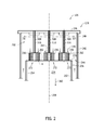
- FIG. 2 is a sectional view of an exemplary embodiment of fuel nozzle assembly 126 and taken along area 2 (shown in FIG. 1 ).
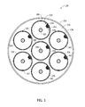
- FIG. 3 is a sectional view of a portion of fuel nozzle assembly 126 taken along line 3-3 in FIG. 2 .
- FIG. 4 is an enlarged cross-sectional view of a portion of fuel nozzle 236 taken along area 4 in FIG. 2 .
- combustor assembly 124 includes a casing 242 that defines a chamber 244 within the casing 242.
- An end cover 246 is coupled to an outer portion 248 of casing 242 such that an air plenum 250 is defined within chamber 244.
- Compressor section 114 (shown in FIG. 1 ) is coupled in flow communication with chamber 244 to channel compressed air downstream from compressor section 114 to air plenum 250.
- each combustor assembly 124 includes a combustor liner 252 that is positioned within chamber 244 and is coupled in flow communication with turbine section 118 (shown in FIG. 1 ) through a transition piece (not shown) and with compressor section 114.
- Combustor liner 252 includes a substantially cylindrically-shaped inner surface 254 that extends between an aft portion (not shown) and a forward portion 256.
- Inner surface 254 defines annular combustion chamber 234 that extends axially along a centerline axis 258, and extends between the aft portion and forward portion 256.
- Combustor liner 252 is coupled to fuel nozzle assembly 126 such that fuel nozzle assembly 126 channels fuel and air into combustion chamber 234.
- Combustion chamber 234 defines a combustion gas flow path 260 that extends from fuel nozzle assembly 126 to turbine section 118.
- fuel nozzle assembly 126 receives a flow of air from air plenum 250, receives a flow of fuel from fuel supply system 138, and channels a mixture of fuel/air into combustion chamber 234 for generating combustion gases.
- Fuel nozzle assembly 126 includes a plurality of fuel nozzles 236 that are each coupled to combustor liner 252, and at least partially positioned within air plenum 250.
- fuel nozzle assembly 126 includes a plurality of outer nozzles 262 that are circumferentially oriented about a center nozzle 264. Center nozzle 264 is oriented along centerline axis 258.
- an end plate 270 is coupled to forward portion 256 of combustor liner 252 such that end plate 270 at least partially defines combustion chamber 234.
- End plate 270 includes a plurality of openings 272 that extend through end plate 270, and are each sized and shaped to receive a fuel nozzle 236 therethrough.
- Each fuel nozzle 236 is positioned within a corresponding opening 272 such that fuel nozzle 236 is coupled in flow communication with combustion chamber 234.
- fuel nozzles 236 may be coupled to combustor liner 252 such that no end plate is needed.
- each fuel nozzle 236 includes a housing 484 (shown in FIG. 4 ).
- Housing 484 includes a sidewall 486 (shown in FIG. 3 ) that extends between a forward endwall 488 and an opposite aft endwall 490.
- Aft endwall 490 is oriented between forward endwall 488 and combustion chamber 234, and includes an outer surface 492 that at least partially defines combustion chamber 234.
- Sidewall 486 includes a radially outer surface 494 and a radially inner surface 496.
- Radially inner surface 496 defines a substantially cylindrical cavity 498 that extends along a longitudinal axis 500 and between forward endwall 488 and aft endwall 490.
- An interior wall 502 is positioned within cavity 498 and extends inwardly from inner surface 496 such that a cooling fluid plenum 504 is defined between interior wall 502 and forward endwall 488, and such that a fuel plenum 506 is defined between interior wall 502 and aft endwall 490.
- interior wall 502 is oriented substantially perpendicularly with respect to sidewall inner surface 496 such that fuel plenum 506 is oriented downstream of cooling fluid plenum 504 along longitudinal axis 500.
- a plurality of cooling fluid conduits 508 extends from cooling fluid supply system 140 (shown in FIG. 1 ) to fuel nozzle assembly 126. Each cooling fluid conduit 508 is coupled in flow communication with corresponding fuel nozzle 236. More specifically, cooling fluid conduit 508 is coupled to cooling fluid plenum 504 for channeling a flow of cooling fluid from cooling fluid supply system 140 to cooling fluid plenum 504. Cooling fluid conduit 508 extends between end cover 246 and housing 484 and includes an inner surface 510 that defines a cooling fluid channel 512 within cooling fluid conduit 508 that is coupled to cooling fluid plenum 504.
- cooling fluid conduit 508 is coupled to forward endwall 488 and is oriented with respect to an opening 514 that extends through forward endwall 488 to couple cooling fluid channel 512 to cooling fluid plenum 504.
- Each cooling fluid channel 512 is coupled to cooling fluid plenum 504 for channeling a flow of cooling fluid 515 from cooling fluid supply system 140 to cooling fluid plenum 504.
- a plurality of fuel conduits 516 extend between fuel supply system 138 (shown in FIG. 1 ) and fuel nozzle assembly 126 for channeling a flow of fuel to fuel nozzle assembly 126.
- each fuel conduit 516 is coupled to a corresponding fuel nozzle 236 for channeling a flow of fuel 518 to fuel plenum 506.
- Each fuel conduit 516 includes an inner surface 520 that defines a fuel channel 522 that is within fuel conduit 516 and coupled in flow communication with fuel plenum 506.
- Fuel conduit 516 is disposed within, and is substantially circumscribed by, cooling fluid conduit 508 and extends through cooling fluid plenum 504 to interior wall 502. Fuel conduit 516 is oriented with respect to an opening 524 that extends through interior wall 502 to couple fuel channel 522 in flow communication with fuel plenum 506.
- fuel nozzle 236 includes a plurality of mixing tubes 528 that are each coupled to housing 484. Each mixing tube 528 extends through housing 484 to couple air plenum 250 to combustion chamber 234. Mixing tubes 528 are oriented in a plurality of rows 530 (shown in FIG. 3 ) that extend outwardly from a center portion 532 (shown in FIG. 3 ) of fuel nozzle assembly 126 towards housing sidewall 486. Each row 530 includes a plurality of mixing tubes 528 that are oriented circumferentially about nozzle center portion 532. Each mixing tube 528 includes an outer surface 534 and a substantially cylindrical inner surface 536, and extends between an inlet portion 538 and an outlet portion 540.
- Mixing tube 528 includes a width 541 measured between inner surface 536 and outer surface 534.
- Inner surface 536 defines a flow channel 542 that extends along a centerline axis 544 between inlet portion 538 and outlet portion 540.
- Inlet portion 538 is sized and shaped to channel a flow of air, represented by arrow 546, from air plenum 250 into flow channel 542 to facilitate mixing fuel and air within flow channel 542.
- Forward endwall 488 includes a plurality of inlet openings 548 that extend through forward endwall 488.
- aft endwall 490 includes a plurality of outlet openings 550 that extend though aft endwall 490.
- Each mixing tube inlet portion 538 is oriented adjacent to forward endwall 488 and extends through a corresponding inlet opening 548.
- outlet portion 540 is oriented adjacent to aft endwall 490 and extends through a corresponding outlet opening 550.
- each mixing tube 528 extends through a plurality of openings 552 that extend through interior wall 502.
- each mixing tube 528 is oriented substantially parallel with respect to longitudinal axis 500.
- at least one mixing tube 528 may be oriented obliquely with respect to longitudinal axis 500.
- one or more mixing tubes 528 include at least one fuel aperture 554 that extends through mixing tube inner surface 536 to couple fuel plenum 506 to flow channel 542.
- Fuel aperture 554 is configured to channel flow of fuel 518 from fuel plenum 506 to flow channel 542 to facilitate mixing fuel 518 with air 546 to form a fuel-air mixture, represented by arrow 558, that is channeled to combustion chamber 234.
- fuel aperture 554 extends along a centerline axis 560 that is oriented substantially perpendicular to flow channel axis 544.
- fuel aperture 554 is oriented obliquely with respect to flow channel axis 544.
- fuel aperture 554 may be oriented at any angle with respect to flow channel axis 544 that enables fuel nozzle 236 to function as described herein.
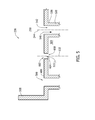
- FIG. 5 is an enlarged schematic view of a portion of an exemplary fuel nozzle 236 shown in FIG. 4 and taken along area 6.
- FIG. 6 is an enlarged schematic view of a portion of an alternative fuel nozzle.
- one or more cooling fluid apertures 602 extend through forward endwall 488 for coupling cooling fluid plenum 504 in flow communication with air plenum 250. Cooling fluid aperture 602 is configured to channel cooling fluid 515 from cooling fluid plenum 504 to air plenum 250.
- Fuel nozzle 236 may have any number and/or arrangement of cooling fluid apertures 602 to enable fuel nozzle assembly 126 to function as described herein.
- cooling fluid aperture 602 has a radially inner surface 604 that defines a flow channel 608 that extends along a centerline axis 610.
- Cooling fluid aperture 602, and therefore centerline axis 610 is substantially parallel to centerline axis 544.
- at least one cooling fluid aperture 602, and therefore centerline axis 610 may be oriented obliquely with respect to centerline axis 544. More particularly, the oblique angle may be between about 30 to 60 degrees.
- fuel is channeled from fuel supply system 138 through fuel conduit 516 and supplied to fuel nozzle assembly 126, wherein the fuel is mixed with at least air to form a combustible mixture. More specifically, fuel is channeled from fuel conduit 516 to at least one aperture 554 located on mixing tube 528. Air and other fluids flow through mixing tube 528, as shown by arrow 546, and mix with fuel to form the combustible mixture.
- the combustible mixture is ignited after discharging from outlet opening 550 of fuel nozzle 236 to combustion chamber 234. High concentrations of H 2 burning in combustion chamber 234 generate a high dynamics tone greater than 1 kHz. The high dynamics tone, in extreme cases, causes damage to combustor section 116 or other parts of turbine engine 100.
- cooling fluid is channeled through cooling fluid conduit 508 to fuel nozzle 236. More specifically, cooling fluid is channeled from cooling fluid supply system 140 (shown in FIG. 1 ) through cooling fluid channel 512 to cooling fluid plenum 504. The cooling fluid is channeled through at least one aperture 602 and discharged into air plenum 250.
- the cooling fluid is mixed with air and/or other fluids present in air plenum 250 before flowing through mixing tube 528, as shown by arrows 546, such that the cooling fluid facilitates the reduction of a temperature, e.g., a local peak, in combustion chamber 234, the reduction of the high dynamics tone and the reduction of NO X .
- a temperature e.g., a local peak
- NO X NO X
- the above-described fuel nozzle assembly may be used with turbine engines to facilitate reducing the peak temperature generated within a combustor.
- the fuel nozzle assembly includes a plurality of fuel nozzles.
- Each of the plurality of fuel nozzles includes a plurality of mixing tubes for channeling air, fuel, and other fluids to the combustion chamber.
- a cooling fluid is channeled through apertures on the cold-side of at least one fuel nozzle for mixing with air and/or other fluids before being channeled through the plurality of tubes to the combustion chamber.
- Exemplary embodiments of a fuel nozzle assembly and method of assembling same are described above in detail.
- the fuel nozzle assembly and method of assembling same are not limited to the specific embodiments described herein, but rather, components of the fuel nozzle assembly and/or steps of the assemblage of the assembly may be utilized independently and separately from other components and/or steps described herein.
- any of the openings described herein may be used with any of the fuel nozzles described herein.
- the fuel nozzle assembly may also be used in combination with other machines and methods, and is not limited to practice with only a turbine engine as described herein. Rather, the exemplary embodiment can be implemented and utilized in connection with many other systems.
Landscapes
- Engineering & Computer Science (AREA)
- Chemical & Material Sciences (AREA)
- Combustion & Propulsion (AREA)
- Mechanical Engineering (AREA)
- General Engineering & Computer Science (AREA)
- Turbine Rotor Nozzle Sealing (AREA)
Applications Claiming Priority (1)
| Application Number | Priority Date | Filing Date | Title |
|---|---|---|---|
| US13/410,168 US20130227928A1 (en) | 2012-03-01 | 2012-03-01 | Fuel nozzle assembly for use in turbine engines and method of assembling same |
Publications (1)
| Publication Number | Publication Date |
|---|---|
| EP2634489A1 true EP2634489A1 (fr) | 2013-09-04 |
Family
ID=47552757
Family Applications (1)
| Application Number | Title | Priority Date | Filing Date |
|---|---|---|---|
| EP12197460.4A Withdrawn EP2634489A1 (fr) | 2012-03-01 | 2012-12-17 | Ensemble de buse de combustible destiné à être utilisé dans des moteurs à turbine et son procédé d'assemblage |
Country Status (4)
| Country | Link |
|---|---|
| US (1) | US20130227928A1 (fr) |
| EP (1) | EP2634489A1 (fr) |
| JP (1) | JP2013181744A (fr) |
| CN (1) | CN103292354A (fr) |
Families Citing this family (2)
| Publication number | Priority date | Publication date | Assignee | Title |
|---|---|---|---|---|
| US8984888B2 (en) * | 2011-10-26 | 2015-03-24 | General Electric Company | Fuel injection assembly for use in turbine engines and method of assembling same |
| JP7200077B2 (ja) | 2019-10-01 | 2023-01-06 | 三菱重工業株式会社 | ガスタービン燃焼器及びその運転方法 |
Citations (3)
| Publication number | Priority date | Publication date | Assignee | Title |
|---|---|---|---|---|
| US4100733A (en) * | 1976-10-04 | 1978-07-18 | United Technologies Corporation | Premix combustor |
| US20100031662A1 (en) * | 2008-08-05 | 2010-02-11 | General Electric Company | Turbomachine injection nozzle including a coolant delivery system |
| US20110197587A1 (en) * | 2010-02-18 | 2011-08-18 | General Electric Company | Multi-tube premixing injector |
Family Cites Families (4)
| Publication number | Priority date | Publication date | Assignee | Title |
|---|---|---|---|---|
| US5778676A (en) * | 1996-01-02 | 1998-07-14 | General Electric Company | Dual fuel mixer for gas turbine combustor |
| US6141954A (en) * | 1998-05-18 | 2000-11-07 | United Technologies Corporation | Premixing fuel injector with improved flame disgorgement capacity |
| US6427446B1 (en) * | 2000-09-19 | 2002-08-06 | Power Systems Mfg., Llc | Low NOx emission combustion liner with circumferentially angled film cooling holes |
| US8205452B2 (en) * | 2009-02-02 | 2012-06-26 | General Electric Company | Apparatus for fuel injection in a turbine engine |
-
2012
- 2012-03-01 US US13/410,168 patent/US20130227928A1/en not_active Abandoned
- 2012-12-17 EP EP12197460.4A patent/EP2634489A1/fr not_active Withdrawn
- 2012-12-21 JP JP2012278789A patent/JP2013181744A/ja active Pending
- 2012-12-31 CN CN2012105914058A patent/CN103292354A/zh active Pending
Patent Citations (3)
| Publication number | Priority date | Publication date | Assignee | Title |
|---|---|---|---|---|
| US4100733A (en) * | 1976-10-04 | 1978-07-18 | United Technologies Corporation | Premix combustor |
| US20100031662A1 (en) * | 2008-08-05 | 2010-02-11 | General Electric Company | Turbomachine injection nozzle including a coolant delivery system |
| US20110197587A1 (en) * | 2010-02-18 | 2011-08-18 | General Electric Company | Multi-tube premixing injector |
Also Published As
| Publication number | Publication date |
|---|---|
| JP2013181744A (ja) | 2013-09-12 |
| US20130227928A1 (en) | 2013-09-05 |
| CN103292354A (zh) | 2013-09-11 |
Similar Documents
| Publication | Publication Date | Title |
|---|---|---|
| EP2669580B1 (fr) | Ensemble d'injection de carburant à utiliser dans les moteurs à turbine et procédé d'assemblage correspondant | |
| US8438851B1 (en) | Combustor assembly for use in a turbine engine and methods of assembling same | |
| US8943832B2 (en) | Fuel nozzle assembly for use in turbine engines and methods of assembling same | |
| US9140454B2 (en) | Bundled multi-tube nozzle for a turbomachine | |
| US9222673B2 (en) | Fuel nozzle and method of assembling the same | |
| CA2528808C (fr) | Methode et appareil pour reduire les proprietes acoustiques d'une chambre de combustion | |
| US8353165B2 (en) | Combustor assembly for use in a turbine engine and methods of fabricating same | |
| US8297059B2 (en) | Nozzle for a turbomachine | |
| US11566790B1 (en) | Methods of operating a turbomachine combustor on hydrogen | |
| US20120031099A1 (en) | Combustor assembly for use in a turbine engine and methods of assembling same | |
| US8813501B2 (en) | Combustor assemblies for use in turbine engines and methods of assembling same | |
| EP2587159B1 (fr) | Ensemble d'injection de carburant à utiliser dans les moteurs à turbine et procédé d'assemblage correspondant | |
| EP2634489A1 (fr) | Ensemble de buse de combustible destiné à être utilisé dans des moteurs à turbine et son procédé d'assemblage | |
| EP2626633B1 (fr) | Moteurs à turbine | |
| EP2626632A2 (fr) | Ensemble d'injection de carburant à utiliser dans les moteurs à turbine et procédé d'assemblage correspondant | |
| US20140251483A1 (en) | Tube assembly for use in fuel injection assemblies and methods of assembling same |
Legal Events
| Date | Code | Title | Description |
|---|---|---|---|
| PUAI | Public reference made under article 153(3) epc to a published international application that has entered the european phase |
Free format text: ORIGINAL CODE: 0009012 |
|
| AK | Designated contracting states |
Kind code of ref document: A1 Designated state(s): AL AT BE BG CH CY CZ DE DK EE ES FI FR GB GR HR HU IE IS IT LI LT LU LV MC MK MT NL NO PL PT RO RS SE SI SK SM TR |
|
| AX | Request for extension of the european patent |
Extension state: BA ME |
|
| 17P | Request for examination filed |
Effective date: 20140304 |
|
| RBV | Designated contracting states (corrected) |
Designated state(s): AL AT BE BG CH CY CZ DE DK EE ES FI FR GB GR HR HU IE IS IT LI LT LU LV MC MK MT NL NO PL PT RO RS SE SI SK SM TR |
|
| STAA | Information on the status of an ep patent application or granted ep patent |
Free format text: STATUS: THE APPLICATION IS DEEMED TO BE WITHDRAWN |
|
| 18D | Application deemed to be withdrawn |
Effective date: 20160701 |