EP2634488B1 - System und Verfahren zur Verringerung der Verbrennungsdynamik in einer Turbomaschine - Google Patents
System und Verfahren zur Verringerung der Verbrennungsdynamik in einer Turbomaschine Download PDFInfo
- Publication number
- EP2634488B1 EP2634488B1 EP12197453.9A EP12197453A EP2634488B1 EP 2634488 B1 EP2634488 B1 EP 2634488B1 EP 12197453 A EP12197453 A EP 12197453A EP 2634488 B1 EP2634488 B1 EP 2634488B1
- Authority
- EP
- European Patent Office
- Prior art keywords
- diluent
- end cap
- combustor
- divider
- tube bundle
- Prior art date
- Legal status (The legal status is an assumption and is not a legal conclusion. Google has not performed a legal analysis and makes no representation as to the accuracy of the status listed.)
- Not-in-force
Links
- 238000002485 combustion reaction Methods 0.000 title claims description 48
- 238000000034 method Methods 0.000 title claims description 21
- 239000003085 diluting agent Substances 0.000 claims description 89
- 239000012530 fluid Substances 0.000 claims description 37
- 239000000446 fuel Substances 0.000 claims description 37
- 238000011144 upstream manufacturing Methods 0.000 claims description 23
- 230000004888 barrier function Effects 0.000 claims description 16
- 238000004891 communication Methods 0.000 claims description 15
- 239000011248 coating agent Substances 0.000 claims description 3
- 238000000576 coating method Methods 0.000 claims description 3
- 239000000567 combustion gas Substances 0.000 description 9
- 239000007789 gas Substances 0.000 description 7
- 230000003993 interaction Effects 0.000 description 6
- 238000013461 design Methods 0.000 description 5
- MWUXSHHQAYIFBG-UHFFFAOYSA-N nitrogen oxide Inorganic materials O=[N] MWUXSHHQAYIFBG-UHFFFAOYSA-N 0.000 description 5
- 238000001816 cooling Methods 0.000 description 4
- 239000000203 mixture Substances 0.000 description 4
- IJGRMHOSHXDMSA-UHFFFAOYSA-N Atomic nitrogen Chemical compound N#N IJGRMHOSHXDMSA-UHFFFAOYSA-N 0.000 description 3
- 230000001965 increasing effect Effects 0.000 description 3
- 239000012720 thermal barrier coating Substances 0.000 description 3
- CURLTUGMZLYLDI-UHFFFAOYSA-N Carbon dioxide Chemical compound O=C=O CURLTUGMZLYLDI-UHFFFAOYSA-N 0.000 description 2
- 238000004519 manufacturing process Methods 0.000 description 2
- 238000012986 modification Methods 0.000 description 2
- 230000004048 modification Effects 0.000 description 2
- 230000007704 transition Effects 0.000 description 2
- UGFAIRIUMAVXCW-UHFFFAOYSA-N Carbon monoxide Chemical compound [O+]#[C-] UGFAIRIUMAVXCW-UHFFFAOYSA-N 0.000 description 1
- UFHFLCQGNIYNRP-UHFFFAOYSA-N Hydrogen Chemical compound [H][H] UFHFLCQGNIYNRP-UHFFFAOYSA-N 0.000 description 1
- 239000003570 air Substances 0.000 description 1
- 239000012080 ambient air Substances 0.000 description 1
- 229910002092 carbon dioxide Inorganic materials 0.000 description 1
- 239000001569 carbon dioxide Substances 0.000 description 1
- 229910002091 carbon monoxide Inorganic materials 0.000 description 1
- 239000000919 ceramic Substances 0.000 description 1
- 238000006243 chemical reaction Methods 0.000 description 1
- 230000006378 damage Effects 0.000 description 1
- 230000003247 decreasing effect Effects 0.000 description 1
- 230000005611 electricity Effects 0.000 description 1
- 230000002708 enhancing effect Effects 0.000 description 1
- 239000002816 fuel additive Substances 0.000 description 1
- 229930195733 hydrocarbon Natural products 0.000 description 1
- 150000002430 hydrocarbons Chemical class 0.000 description 1
- 239000001257 hydrogen Substances 0.000 description 1
- 229910052739 hydrogen Inorganic materials 0.000 description 1
- 239000011261 inert gas Substances 0.000 description 1
- 239000007788 liquid Substances 0.000 description 1
- 238000012423 maintenance Methods 0.000 description 1
- 229910052757 nitrogen Inorganic materials 0.000 description 1
- 230000003647 oxidation Effects 0.000 description 1
- 238000007254 oxidation reaction Methods 0.000 description 1
- 230000037361 pathway Effects 0.000 description 1
- 238000010248 power generation Methods 0.000 description 1
- 238000012552 review Methods 0.000 description 1
- 230000009528 severe injury Effects 0.000 description 1
- -1 steam Substances 0.000 description 1
- XLYOFNOQVPJJNP-UHFFFAOYSA-N water Substances O XLYOFNOQVPJJNP-UHFFFAOYSA-N 0.000 description 1
Images


Classifications
-
- F—MECHANICAL ENGINEERING; LIGHTING; HEATING; WEAPONS; BLASTING
- F23—COMBUSTION APPARATUS; COMBUSTION PROCESSES
- F23R—GENERATING COMBUSTION PRODUCTS OF HIGH PRESSURE OR HIGH VELOCITY, e.g. GAS-TURBINE COMBUSTION CHAMBERS
- F23R3/00—Continuous combustion chambers using liquid or gaseous fuel
- F23R3/28—Continuous combustion chambers using liquid or gaseous fuel characterised by the fuel supply
- F23R3/286—Continuous combustion chambers using liquid or gaseous fuel characterised by the fuel supply having fuel-air premixing devices
-
- F—MECHANICAL ENGINEERING; LIGHTING; HEATING; WEAPONS; BLASTING
- F02—COMBUSTION ENGINES; HOT-GAS OR COMBUSTION-PRODUCT ENGINE PLANTS
- F02C—GAS-TURBINE PLANTS; AIR INTAKES FOR JET-PROPULSION PLANTS; CONTROLLING FUEL SUPPLY IN AIR-BREATHING JET-PROPULSION PLANTS
- F02C3/00—Gas-turbine plants characterised by the use of combustion products as the working fluid
- F02C3/20—Gas-turbine plants characterised by the use of combustion products as the working fluid using a special fuel, oxidant, or dilution fluid to generate the combustion products
- F02C3/30—Adding water, steam or other fluids for influencing combustion, e.g. to obtain cleaner exhaust gases
-
- F—MECHANICAL ENGINEERING; LIGHTING; HEATING; WEAPONS; BLASTING
- F23—COMBUSTION APPARATUS; COMBUSTION PROCESSES
- F23R—GENERATING COMBUSTION PRODUCTS OF HIGH PRESSURE OR HIGH VELOCITY, e.g. GAS-TURBINE COMBUSTION CHAMBERS
- F23R3/00—Continuous combustion chambers using liquid or gaseous fuel
- F23R3/002—Wall structures
-
- F—MECHANICAL ENGINEERING; LIGHTING; HEATING; WEAPONS; BLASTING
- F23—COMBUSTION APPARATUS; COMBUSTION PROCESSES
- F23R—GENERATING COMBUSTION PRODUCTS OF HIGH PRESSURE OR HIGH VELOCITY, e.g. GAS-TURBINE COMBUSTION CHAMBERS
- F23R3/00—Continuous combustion chambers using liquid or gaseous fuel
- F23R3/42—Continuous combustion chambers using liquid or gaseous fuel characterised by the arrangement or form of the flame tubes or combustion chambers
- F23R3/54—Reverse-flow combustion chambers
-
- F—MECHANICAL ENGINEERING; LIGHTING; HEATING; WEAPONS; BLASTING
- F23—COMBUSTION APPARATUS; COMBUSTION PROCESSES
- F23C—METHODS OR APPARATUS FOR COMBUSTION USING FLUID FUEL OR SOLID FUEL SUSPENDED IN A CARRIER GAS OR AIR
- F23C2900/00—Special features of, or arrangements for combustion apparatus using fluid fuels or solid fuels suspended in air; Combustion processes therefor
- F23C2900/07022—Delaying secondary air introduction into the flame by using a shield or gas curtain
-
- F—MECHANICAL ENGINEERING; LIGHTING; HEATING; WEAPONS; BLASTING
- F23—COMBUSTION APPARATUS; COMBUSTION PROCESSES
- F23D—BURNERS
- F23D14/00—Burners for combustion of a gas, e.g. of a gas stored under pressure as a liquid
- F23D14/46—Details, e.g. noise reduction means
- F23D14/62—Mixing devices; Mixing tubes
-
- F—MECHANICAL ENGINEERING; LIGHTING; HEATING; WEAPONS; BLASTING
- F23—COMBUSTION APPARATUS; COMBUSTION PROCESSES
- F23R—GENERATING COMBUSTION PRODUCTS OF HIGH PRESSURE OR HIGH VELOCITY, e.g. GAS-TURBINE COMBUSTION CHAMBERS
- F23R2900/00—Special features of, or arrangements for continuous combustion chambers; Combustion processes therefor
- F23R2900/00013—Reducing thermo-acoustic vibrations by active means
-
- F—MECHANICAL ENGINEERING; LIGHTING; HEATING; WEAPONS; BLASTING
- F23—COMBUSTION APPARATUS; COMBUSTION PROCESSES
- F23R—GENERATING COMBUSTION PRODUCTS OF HIGH PRESSURE OR HIGH VELOCITY, e.g. GAS-TURBINE COMBUSTION CHAMBERS
- F23R3/00—Continuous combustion chambers using liquid or gaseous fuel
- F23R3/28—Continuous combustion chambers using liquid or gaseous fuel characterised by the fuel supply
- F23R3/30—Continuous combustion chambers using liquid or gaseous fuel characterised by the fuel supply comprising fuel prevapourising devices
- F23R3/32—Continuous combustion chambers using liquid or gaseous fuel characterised by the fuel supply comprising fuel prevapourising devices being tubular
Definitions
- the present invention generally involves a system and method for reducing combustion dynamics in a combustor.
- Combustors are commonly used in industrial and power generation operations to ignite fuel to produce combustion gases having a high temperature and pressure.
- gas turbines typically include one or more combustors to generate power or thrust.
- a typical gas turbine used to generate electrical power includes an axial compressor at the front, one or more combustors around the middle, and a turbine at the rear.
- Ambient air may be supplied to the compressor, and rotating blades and stationary vanes in the compressor progressively impart kinetic energy to the working fluid (air) to produce a compressed working fluid at a highly energized state.
- the compressed working fluid exits the compressor and flows through one or more nozzles into a combustion chamber in each combustor where the compressed working fluid mixes with fuel and ignites to generate combustion gases having a high temperature and pressure.
- the combustion gases expand in the turbine to produce work. For example, expansion of the combustion gases in the turbine may rotate a shaft connected to a generator to produce electricity.
- combustion gas temperatures generally improve the thermodynamic efficiency of the combustor.
- higher combustion gas temperatures also promote flashback or flame holding conditions in which the combustion flame migrates towards the fuel being supplied by the nozzles, possibly causing severe damage to the nozzles in a relatively short amount of time.
- higher combustion gas temperatures generally increase the disassociation rate of diatomic nitrogen, increasing the production of nitrogen oxides (NO x ).
- a lower combustion gas temperature associated with reduced fuel flow and/or part load operation (turndown) generally reduces the chemical reaction rates of the combustion gases, increasing the production of carbon monoxide and unburned hydrocarbons.
- a plurality of premixer tubes may be radially arranged in an end cap to provide fluid communication for the working fluid and fuel through the end cap and into the combustion chamber.
- some fuels and operating conditions produce very high frequencies with high hydrogen fuel composition in the combustor.
- Increased vibrations in the combustor associated with high frequencies may reduce the useful life of one or more combustor components.
- high frequencies of combustion dynamics may produce pressure pulses inside the premixer tubes and/or combustion chamber that affect the stability of the combustion flame, reduce the design margins for flashback or flame holding, and/or increase undesirable emissions.
- This document discloses a system comprising an end cap having an upstream surface axially separated from a downstream surface, a plurality of tube bundles extending from the upstream surface through the downstream surface, a divider inside each tube bundle which defines a diluent passage extending axially through the downstream surface and a diluent supply in fluid communication with the divider.
- One aspect of the present invention is a system for reducing combustion dynamics in a combustor.
- the system includes an end cap that extends radially across at least a portion of the combustor, wherein the end cap comprises an upstream surface axially separated from a downstream surface.
- a plurality of tube bundles extends from the upstream surface through the downstream surface of the end cap, and each tube bundle provides fluid communication through the end cap.
- a first divider inside a first tube bundle defines a first diluent passage that extends axially through the downstream surface.
- a diluent supply in fluid communication with the first divider provides diluent flow to the first diluent passage in the first divider.
- a second divider is provided between at least one pair of adjacent tube bundles, wherein the second divider defines a second diluent passage that extends axially through the downstream surface.
- the present invention also includes a method for reducing combustion dynamics in a combustor. The method includes flowing a fuel through a plurality of tube bundles that extend axially through an end cap that extends radially across at least a portion of the combustor.
- the method also includes flowing a diluent through a first diluent passage inside a first tube bundle into a combustion chamber downstream from the end cap, wherein the first diluent passage extends axially through at least a portion of the end cap, and forming a diluent barrier in the combustion chamber between the first tube bundle and at least one other adjacent tube bundle.
- Various embodiments of the present invention include a system and method for reducing combustion dynamics in a combustor.
- the system and method generally include a plurality of tube bundles radially arranged in an end cap.
- the tube bundles supply a mixture of fuel and working fluid to a combustion chamber downstream from the end cap.
- a divider inside one or more tube bundles produces a diluent barrier between at least one pair of adjacent tube bundles to decouple flame interaction between the adjacent tube bundles and thus reduce the combustion dynamics in the combustor.
- Another divider provided between at least one pair of adjacent tube bundles defines a second diluent passage.
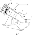
- Fig. 1 shows a simplified cross-section of an exemplary combustor 10, such as would be included in a gas turbine, according to one embodiment of the present invention.
- a casing 12 and end cover 14 may surround the combustor 10 to contain a working fluid 15 flowing to the combustor 10.
- the working fluid 15 may pass through flow holes 16 in an impingement sleeve 18 to flow along the outside of a transition piece 20 and liner 22 to provide convective cooling to the transition piece 20 and liner 22.
- the working fluid 15 When the working fluid 15 reaches the end cover 14, the working fluid 15 reverses direction to flow through a plurality of tube bundles 24 into a combustion chamber 26.
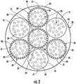
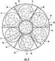
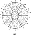
- the tube bundles 24 are radially arranged in different shapes, numbers, and sizes in an end cap 28 upstream from the combustion chamber 26, and Figs. 2-5 provide upstream views of exemplary arrangements of the tube bundles 24 in the end cap 28 within the scope of the present invention.
- the tube bundles 24 may be radially arranged across the end cap 28 in circular groups of premixer tubes 30 enclosed by outer shrouds 31, with six tube bundles 24 surrounding one tube bundle 24.
- the tube bundles 24 may be arranged as a circular group of premixer tubes 30 surrounded by the outer shroud 31surrounded by a series of pie-shaped groups of premixer tubes 30.
- alternating pie-shaped groups of premixer tubes 30 are at least partially enclosed by the outer shroud 31.
- One of ordinary skill in the art will readily appreciate multiple possible combinations of shapes, numbers, and sizes of the tube bundles 24, and the present invention is not limited to any particular arrangement of tube bundles 24 unless specifically recited in the claims.
- the flow of fuel and/or working fluid 15 through the premixer tubes 30 and/or tube bundles 24 may produce undesirable combustion dynamics in the combustion chamber 26, particularly when the fuel and/or working fluid 15 flow is approximately equal between each tube bundle 24.
- various embodiments of the present invention include one or more features to decouple the combustion flame interaction between the adjacent tube bundles 24 and thus reduce the combustion dynamics in the combustor 10.
- the features are generally arranged inside and between one or more tube bundles 24 and define a structural and/or a fluid barrier between one or more pairs of adjacent tube bundles 24 that separates the adjacent tube bundles 24. In this manner, the structural and/or fluid barrier prevents interaction between the combustion flames produced by the adjacent tube bundles 24 to reduce the undesirable combustion dynamics in the combustion chamber 26.
- a first divider 32 inside or around the center tube bundle 24 may define a first diluent passage 34 that separates the center tube bundle 24 from the other tube bundles radially arranged in the end cap 28.
- the first diluent passage 34 generally terminates at one or more diluent ports 36 that provide fluid communication for a diluent to flow through the end cap 28 between the adjacent tube bundles 24. In this manner, the diluent flow through the first divider 32 may sufficiently decouple any combustion flame interaction between the center tube bundle 24 and the other tube bundles 24 radially arranged in the end cap 28.
- additional dividers 38 may be arranged inside or between one or more of the tube bundles 24 radially arranged in the end cap 28 to define additional diluent passages 40 and diluent ports 36 between the one or more tube bundles 24 radially arranged in the end cap 28.
- additional dividers 38 inside alternating tube bundles 24 radially arranged in the end cap 28 provide at least one divider 32, 38 and diluent passage 34, 40 between any two adjacent tube bundles 24.
- Figs. 2 and 4 additional dividers 38 inside alternating tube bundles 24 radially arranged in the end cap 28 provide at least one divider 32, 38 and diluent passage 34, 40 between any two adjacent tube bundles 24.
- the additional dividers 38 may be arranged between one or more of the tube bundles 24 radially arranged in the end cap 28 to again provide at least one divider 32, 38 and diluent passage 34, 40 between any two adjacent tube bundles 24.
- Fig. 6 provides an enlarged cross-section view of an exemplary tube bundle 24 such as is shown in Fig. 1 and the center of Figs. 2-5 according to a first embodiment of the present invention.
- the tube bundle 24 generally includes an upstream surface 42 axially separated from a downstream surface 44.
- Each premixer tube 30 includes a tube inlet 46 proximate to the upstream surface 42 and extends through the downstream surface 44 to provide fluid communication for the working fluid 15 to flow through the tube bundle 24 and into the combustion chamber 26.
- the cross-section of the premixer tubes 30 may be any geometric shape, and the present invention is not limited to any particular cross-section unless specifically recited in the claims.
- An inner shroud 48 circumferentially surrounds at least a portion of the tube bundle 24 to partially define a fuel plenum 50 and a diluent plenum 52 between the upstream and downstream surfaces 42, 44.
- a generally horizontal barrier 54 may extend radially between the upstream surface 42 and the downstream surface 44 to axially separate the fuel plenum 50 from the diluent plenum 52.
- the upstream surface 42, inner shroud 48, and barrier 54 enclose or define the fuel plenum 50 around the upstream portion of the premixer tubes 30, and the downstream surface 44, inner shroud 48, and barrier 54 enclose or define the diluent plenum 52 around the downstream portion of the premixer tubes 30.
- a fuel supply 56 and a diluent supply 58 may extend through the end cover 14 and through the upstream surface 42 to provide fluid communication for fuel and diluent to flow through the end cover 14 to the respective fuel or diluent plenums 50, 52 in each tube bundle 24.
- the fuel supplied to the tube bundle 24 may include any liquid or gaseous fuel suitable for combustion, and possible diluents supplied to the tube bundle 24 may include water, steam, fuel additives, various inert gases such as nitrogen and/or various non-flammable gases such as carbon dioxide or combustion exhaust gases.
- the fuel supply 56 is substantially concentric with the diluent supply 58, although such is not a limitation of the present invention unless specifically recited in the claims.
- One or more of the premixer tubes 30 may include a fuel port 60 that provides fluid communication from the fuel plenum 50 into the one or more premixer tubes 30.
- the fuel ports 60 may be angled radially, axially, and/or azimuthally to project and/or impart swirl to the fuel flowing through the fuel ports 60 and into the premixer tubes 30.
- the working fluid 15 may flow through the tube inlets 46 and into the premixer tubes 30, and fuel from the fuel plenum 50 may flow through the fuel ports 60 and into the premixer tubes 30 to mix with the working fluid 15.
- the fuel-working fluid mixture may then flow through the premixer tubes 30 and into the combustion chamber 26.
- the diluent may flow from the diluent supply 58 around the premixer tubes 30 in the diluent plenum 52 to provide convective cooling to the premixer tubes 30 and/or impingement cooling to the downstream surface 44.
- the diluent may then flow through diluent ports 62 in the divider 32 and into the diluent passage 34.
- the diluent may then flow through the diluent ports 36 in the diluent passage and into the combustion chamber 26. In this manner, the diluent may form a barrier between adjacent tube bundles 24 to separate the combustion flames of adjacent tube bundles 24, thereby reducing or preventing any interaction between the combustion flames of adjacent tube bundles 24.
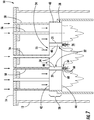
- Fig. 7 provides an enlarged cross-section view of a portion of the combustor 10 shown in Figs. 1 and 4 according to an alternate embodiment of the present invention
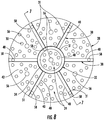
- Fig. 8 provides a downstream axial view of the end cap 28 shown in Fig. 7
- the end cap 28 generally extends radially across at least a portion of the combustor 10 and includes the upstream and downstream surfaces 42, 44 previously described with respect to the tube bundle 24 shown in Fig. 6 .
- one or more tube bundles 24 extend from the upstream surface 42 through the downstream surface 44 to provide fluid communication for fuel and/or working fluid 15 through the end cap 28.
- Figs. 7 provides an enlarged cross-section view of a portion of the combustor 10 shown in Figs. 1 and 4 according to an alternate embodiment of the present invention
- Fig. 8 provides a downstream axial view of the end cap 28 shown in Fig. 7
- the end cap 28 generally extends radially across at least a portion of the combustor 10 and includes the up
- the fuel supply 56 is in fluid communication with the tube bundles 24, and the diluent supply 58 is in fluid communication with the diluent passages 34, 40 defined by the dividers 32, 38.
- the diluent passages 34, 40 extend axially through at least a portion of the end cap 28 and through the downstream surface 44 to separate one or more pairs of adjacent tube bundles 24. In this manner, the diluent supply 58 may supply diluent to and through the diluent passages 34, 40 and into the combustion chamber 26 between the adjacent tube bundles 24.
- one or more of the diluent passages 34, 40 terminate at a plurality of diluent distributors 64.
- the diluent distributors 64 may reside inside the diluent passages 34, 40 or may extend downstream from the downstream surface 44 as shown in Fig. 7 .
- the diluent distributors 64 provide a physical barrier between adjacent tube bundles 24 and may include a plurality of diluent injectors 66 that project the diluent into the combustion chamber 26 between adjacent tube bundles 24.
- the diluent flowing through the diluent distributors 64 provides convective and/or film cooling to the diluent distributors 64.
- a thermal barrier coating 68 on the downstream surface of the diluent distributors 64 may protect the diluent distributors 64 from excessive thermal loading and/or oxidation associated with the combustion flame.
- the thermal barrier coating 68 may include a plurality of layers that include at least a metallic bond coating, a thermally prepared oxide, and/or a ceramic top coating, although the particular composition and structure of the thermal barrier coating 68 is not a limitation of the present invention unless specifically recited in the claims.
- the various embodiments described and illustrated with respect to Figs. 1-8 may also provide a method for reducing combustion dynamics in the combustor 10.
- the method may include flowing the fuel through one or more tube bundles 24 that extend axially through the end cap 28 that extends radially across at least a portion of the combustor 10.
- the method may further include flowing the diluent through one or more diluent passages 34, 40 inside and between one or more tube bundles 24 into the combustion chamber 26 downstream from the end cap 28, wherein the diluent passages 34, 40 separate at least one pair of adjacent tube bundles 24 and extend axially through at least a portion of the end cap 28.
- the method may form a diluent barrier in the combustion chamber 26 between the adjacent tube bundles 24.
- the method may form the diluent barrier completely around one or more tube bundles 24 and between each pair of adjacent tube bundles 24.
- the method may inject the diluent into the combustion chamber 26 downstream from the end cap 28 and/or flow the fuel concentrically with the diluent through at least a portion of the combustor 10.
- the systems and methods described herein may provide one or more of the following advantages over existing nozzles and combustors.
- the diluent barrier created by the dividers 32 and/or diluent passages 34 decouple flame interaction between the adjacent tube bundles 24 and thus reduce the combustion dynamics in the combustor 10.
- the reduced combustion dynamics in the combustor 10 may extend the operating capability of the combustor 10 over a wide range of fuels without decreasing the useful life and/or maintenance intervals for various combustor 10 components.
- the reduced combustion dynamics may maintain or increase the design margin against flashback or flame holding and/or reduce undesirable emissions over a wide range of combustor 10 operating levels.
Landscapes
- Engineering & Computer Science (AREA)
- Chemical & Material Sciences (AREA)
- Combustion & Propulsion (AREA)
- Mechanical Engineering (AREA)
- General Engineering & Computer Science (AREA)
- Portable Nailing Machines And Staplers (AREA)
Claims (11)
- System zur Verringerung der Verbrennungsdynamik in einer Brennkammer (10), umfassend:a. eine Endkappe (28), die sich radial über mindestens einen Abschnitt der Brennkammer (10) erstreckt, wobei die Endkappe (28) eine stromaufwärtige Oberfläche (42) umfasst, die von einer stromabwärtigen Oberfläche (44) axial getrennt ist;b. mehrere Rohrbündel (24), die sich von der stromaufwärtigen Oberfläche (42) durch die stromabwärtige Oberfläche (44) der Endkappe (28) erstrecken, wobei jedes Rohrbündel (24) eine Fluidverbindung durch die Endkappe (28) bereitstellt;c. eine erste Trennwand (32) innerhalb eines ersten Rohrbündels (24), wobei die erste Trennwand (32) einen ersten Verdünnungsmitteldurchlass (34) definiert, der sich axial durch die stromabwärtige Oberfläche (44) erstreckt;d. eine Verdünnungsmittelzufuhr (58) in Fluidverbindung mit der ersten Trennwand (32), wobei die Verdünnungsmittelzufuhr (58) einen Verdünnungsmittelfluss zu dem ersten Verdünnungsmitteldurchlass (34) in der ersten Trennwand (32) bereitstellt; unde. eine zweite Trennwand (38) zwischen mindestens einem Paar von angrenzenden Rohrbündeln (24), wobei die zweite Trennwand (38) einen zweiten Verdünnungsmitteldurchlass (40) definiert, der sich axial durch die stromabwärtige Oberfläche (44) erstreckt.
- System nach Anspruch 1, das ferner eine zweite Trennwand (38) innerhalb eines zweiten Rohrbündels (24) umfasst, wobei die zweite Trennwand (38) einen zweiten Verdünnungsmitteldurchlass (40) definiert, der sich axial durch die stromabwärtige Oberfläche (44) erstreckt.
- System nach einem der Ansprüche 1 oder 2, wobei der erste Verdünnungsmitteldurchlass (34) an mehreren Verdünnungsmittelanschlüssen (62) endet, die eine Fluidverbindung für den Verdünnungsmittelfluss durch die stromabwärtige Oberfläche (44) der Endkappe (28) bereitstellen.
- System nach einem der Ansprüche 1 oder 2, wobei der erste Verdünnungsmitteldurchlass (34) an mehreren Verdünnungsmittelverteilern (64) endet, die sich von der stromabwärtigen Oberfläche (44) stromabwärts erstrecken.
- System nach Anspruch 4, das ferner eine Wärmedämmschicht (68) auf den mehreren Verdünnungsmittelverteilern (64) umfasst.
- System nach einem der vorhergehenden Ansprüche, das ferner eine Brennstoffzufuhr (56) in Fluidverbindung mit jedem Rohrbündel (24) umfasst, wobei die Brennstoffzufuhr (56) im Wesentlichen konzentrisch zu der Verdünnungsmittelzufuhr (58) ist.
- Verfahren zur Verringerung der Verbrennungsdynamik in einer Brennkammer (10), umfassend:a. Fließen eines Brennstoffs durch mehrere Rohrbündel (24), die sich axial durch eine Endkappe (28) erstrecken, die sich radial über mindestens einen Abschnitt der Brennkammer (10) erstreckt;b. Fließen des Verdünnungsmittels durch einen ersten Verdünnungsmitteldurchlass (34) innerhalb eines ersten Rohrbündels (24) in eine Brennkammer (26) stromabwärts der Endkappe (28), wobei sich der erste Verdünnungsmitteldurchlass (34) axial durch mindestens einen Abschnitt der Endkappe (28) erstreckt; undc. Bilden einer Verdünnungsmittelbarriere in der Brennkammer (26) zwischen dem ersten Rohrbündel (24) und mindestens einem anderen angrenzenden Rohrbündel (24).
- Verfahren nach Anspruch 7, das ferner ein Bilden der Verdünnungsmittelbarriere um das erste Rohrbündel (24) herum umfasst.
- Verfahren nach Anspruch 7, das ferner ein Bilden der Verdünnungsmittelbarriere zwischen jedem Paar von angrenzenden Rohrbündeln (24) umfasst.
- Verfahren nach Anspruch 7, 8 oder 9, das ferner ein Einspritzen des Verdünnungsmittels in die Brennkammer (26) stromabwärts der Endkappe (28) umfasst.
- Verfahren nach einem der Ansprüche 7 bis 10, das ferner ein Fließen des Brennstoffs konzentrisch zu dem Verdünnungsmittel durch mindestens einen Abschnitt der Brennkammer (10) umfasst.
Applications Claiming Priority (1)
| Application Number | Priority Date | Filing Date | Title |
|---|---|---|---|
| US13/409,309 US9121612B2 (en) | 2012-03-01 | 2012-03-01 | System and method for reducing combustion dynamics in a combustor |
Publications (2)
| Publication Number | Publication Date |
|---|---|
| EP2634488A1 EP2634488A1 (de) | 2013-09-04 |
| EP2634488B1 true EP2634488B1 (de) | 2017-09-20 |
Family
ID=47598630
Family Applications (1)
| Application Number | Title | Priority Date | Filing Date |
|---|---|---|---|
| EP12197453.9A Not-in-force EP2634488B1 (de) | 2012-03-01 | 2012-12-17 | System und Verfahren zur Verringerung der Verbrennungsdynamik in einer Turbomaschine |
Country Status (5)
| Country | Link |
|---|---|
| US (1) | US9121612B2 (de) |
| EP (1) | EP2634488B1 (de) |
| JP (1) | JP6050675B2 (de) |
| CN (1) | CN103292353B (de) |
| RU (1) | RU2012158332A (de) |
Families Citing this family (9)
| Publication number | Priority date | Publication date | Assignee | Title |
|---|---|---|---|---|
| US9506654B2 (en) * | 2011-08-19 | 2016-11-29 | General Electric Company | System and method for reducing combustion dynamics in a combustor |
| US9677766B2 (en) * | 2012-11-28 | 2017-06-13 | General Electric Company | Fuel nozzle for use in a turbine engine and method of assembly |
| WO2015176908A1 (de) * | 2014-05-23 | 2015-11-26 | Siemens Aktiengesellschaft | Brenner mit brennstoffverteilerring |
| JP6979343B2 (ja) * | 2017-11-30 | 2021-12-15 | 三菱パワー株式会社 | 燃料噴射器、燃焼器、及びガスタービン |
| JP2020085284A (ja) | 2018-11-20 | 2020-06-04 | 三菱日立パワーシステムズ株式会社 | 燃焼器及びガスタービン |
| CN110131711A (zh) * | 2019-06-14 | 2019-08-16 | 中山市三诺燃气具有限公司 | 可调节燃烧角度的红外线燃烧器 |
| JP7270517B2 (ja) * | 2019-10-01 | 2023-05-10 | 三菱重工業株式会社 | ガスタービン燃焼器 |
| KR102469577B1 (ko) * | 2020-12-31 | 2022-11-21 | 두산에너빌리티 주식회사 | 마이크로 믹서 및 이를 포함하는 연소기 |
| JP2023104876A (ja) * | 2022-01-18 | 2023-07-28 | ドゥサン エナービリティー カンパニー リミテッド | 燃焼器用ノズル、燃焼器およびこれを含むガスタービン |
Citations (1)
| Publication number | Priority date | Publication date | Assignee | Title |
|---|---|---|---|---|
| EP2587157A2 (de) * | 2011-10-26 | 2013-05-01 | General Electric Company | System und Verfahren zur Verringerung der Verbrennungsdynamik und NOx in einer Brennkammer |
Family Cites Families (60)
| Publication number | Priority date | Publication date | Assignee | Title |
|---|---|---|---|---|
| US3771500A (en) | 1971-04-29 | 1973-11-13 | H Shakiba | Rotary engine |
| US4100733A (en) | 1976-10-04 | 1978-07-18 | United Technologies Corporation | Premix combustor |
| US4104873A (en) | 1976-11-29 | 1978-08-08 | The United States Of America As Represented By The Administrator Of The United States National Aeronautics And Space Administration | Fuel delivery system including heat exchanger means |
| DE2950535A1 (de) * | 1979-11-23 | 1981-06-11 | BBC AG Brown, Boveri & Cie., Baden, Aargau | Brennkammer einer gasturbine mit vormisch/vorverdampf-elementen |
| US4412414A (en) | 1980-09-22 | 1983-11-01 | General Motors Corporation | Heavy fuel combustor |
| SE455438B (sv) | 1986-11-24 | 1988-07-11 | Aga Ab | Sett att senka en brennares flamtemperatur samt brennare med munstycken for oxygen resp brensle |
| US4845952A (en) * | 1987-10-23 | 1989-07-11 | General Electric Company | Multiple venturi tube gas fuel injector for catalytic combustor |
| DE4041628A1 (de) | 1990-12-22 | 1992-07-02 | Daimler Benz Ag | Gemischverdichtende brennkraftmaschine mit sekundaerlufteinblasung und mit luftmassenmessung im saugrohr |
| DE4100657A1 (de) | 1991-01-11 | 1992-07-16 | Rothenberger Werkzeuge Masch | Tragbarer brenner fuer brenngas mit zwei mischrohren |
| FR2689964B1 (fr) | 1992-04-08 | 1994-05-27 | Snecma | Chambre de combustion munie d'un fond generateur de premelange. |
| US5439532A (en) | 1992-06-30 | 1995-08-08 | Jx Crystals, Inc. | Cylindrical electric power generator using low bandgap thermophotovolatic cells and a regenerative hydrocarbon gas burner |
| FR2712378B1 (fr) | 1993-11-10 | 1995-12-29 | Stein Industrie | Réacteur à lit fluidisé circulant à extensions de surface d'échange thermique. |
| FR2717250B1 (fr) | 1994-03-10 | 1996-04-12 | Snecma | Système d'injection à prémélange. |
| KR100550689B1 (ko) | 1998-02-10 | 2006-02-08 | 제너럴 일렉트릭 캄파니 | 가스 터빈의 연소 시스템용 버너 및 연료와 공기의 예비혼합 방법 |
| US6098407A (en) | 1998-06-08 | 2000-08-08 | United Technologies Corporation | Premixing fuel injector with improved secondary fuel-air injection |
| US6123542A (en) | 1998-11-03 | 2000-09-26 | American Air Liquide | Self-cooled oxygen-fuel burner for use in high-temperature and high-particulate furnaces |
| US6358040B1 (en) | 2000-03-17 | 2002-03-19 | Precision Combustion, Inc. | Method and apparatus for a fuel-rich catalytic reactor |
| US6796790B2 (en) | 2000-09-07 | 2004-09-28 | John Zink Company Llc | High capacity/low NOx radiant wall burner |
| US6931862B2 (en) | 2003-04-30 | 2005-08-23 | Hamilton Sundstrand Corporation | Combustor system for an expendable gas turbine engine |
| US7127899B2 (en) * | 2004-02-26 | 2006-10-31 | United Technologies Corporation | Non-swirl dry low NOx (DLN) combustor |
| US7003958B2 (en) | 2004-06-30 | 2006-02-28 | General Electric Company | Multi-sided diffuser for a venturi in a fuel injector for a gas turbine |
| US6983600B1 (en) | 2004-06-30 | 2006-01-10 | General Electric Company | Multi-venturi tube fuel injector for gas turbine combustors |
| US7007478B2 (en) | 2004-06-30 | 2006-03-07 | General Electric Company | Multi-venturi tube fuel injector for a gas turbine combustor |
| US20080016876A1 (en) | 2005-06-02 | 2008-01-24 | General Electric Company | Method and apparatus for reducing gas turbine engine emissions |
| JP4728176B2 (ja) * | 2005-06-24 | 2011-07-20 | 株式会社日立製作所 | バーナ、ガスタービン燃焼器及びバーナの冷却方法 |
| US7752850B2 (en) | 2005-07-01 | 2010-07-13 | Siemens Energy, Inc. | Controlled pilot oxidizer for a gas turbine combustor |
| US7631499B2 (en) | 2006-08-03 | 2009-12-15 | Siemens Energy, Inc. | Axially staged combustion system for a gas turbine engine |
| US7832212B2 (en) * | 2006-11-10 | 2010-11-16 | General Electric Company | High expansion fuel injection slot jet and method for enhancing mixing in premixing devices |
| JP4735548B2 (ja) * | 2007-01-17 | 2011-07-27 | 株式会社日立製作所 | 高湿分空気利用ガスタービン及びその運転方法 |
| US8127547B2 (en) | 2007-06-07 | 2012-03-06 | United Technologies Corporation | Gas turbine engine with air and fuel cooling system |
| US20090297996A1 (en) | 2008-05-28 | 2009-12-03 | Advanced Burner Technologies Corporation | Fuel injector for low NOx furnace |
| US8147121B2 (en) | 2008-07-09 | 2012-04-03 | General Electric Company | Pre-mixing apparatus for a turbine engine |
| US8186166B2 (en) | 2008-07-29 | 2012-05-29 | General Electric Company | Hybrid two fuel system nozzle with a bypass connecting the two fuel systems |
| US8112999B2 (en) * | 2008-08-05 | 2012-02-14 | General Electric Company | Turbomachine injection nozzle including a coolant delivery system |
| FI122203B (fi) | 2008-09-11 | 2011-10-14 | Raute Oyj | Aaltojohtoelementti |
| US7886991B2 (en) | 2008-10-03 | 2011-02-15 | General Electric Company | Premixed direct injection nozzle |
| US8007274B2 (en) | 2008-10-10 | 2011-08-30 | General Electric Company | Fuel nozzle assembly |
| US8327642B2 (en) | 2008-10-21 | 2012-12-11 | General Electric Company | Multiple tube premixing device |
| US8209986B2 (en) | 2008-10-29 | 2012-07-03 | General Electric Company | Multi-tube thermal fuse for nozzle protection from a flame holding or flashback event |
| US8454350B2 (en) * | 2008-10-29 | 2013-06-04 | General Electric Company | Diluent shroud for combustor |
| US9140454B2 (en) | 2009-01-23 | 2015-09-22 | General Electric Company | Bundled multi-tube nozzle for a turbomachine |
| US8539773B2 (en) * | 2009-02-04 | 2013-09-24 | General Electric Company | Premixed direct injection nozzle for highly reactive fuels |
| US8424311B2 (en) * | 2009-02-27 | 2013-04-23 | General Electric Company | Premixed direct injection disk |
| US8234871B2 (en) | 2009-03-18 | 2012-08-07 | General Electric Company | Method and apparatus for delivery of a fuel and combustion air mixture to a gas turbine engine using fuel distribution grooves in a manifold disk with discrete air passages |
| US8157189B2 (en) | 2009-04-03 | 2012-04-17 | General Electric Company | Premixing direct injector |
| US20100281876A1 (en) * | 2009-05-05 | 2010-11-11 | Abdul Rafey Khan | Fuel blanketing by inert gas or less reactive fuel layer to prevent flame holding in premixers |
| US8607568B2 (en) | 2009-05-14 | 2013-12-17 | General Electric Company | Dry low NOx combustion system with pre-mixed direct-injection secondary fuel nozzle |
| US8616002B2 (en) | 2009-07-23 | 2013-12-31 | General Electric Company | Gas turbine premixing systems |
| US8794545B2 (en) | 2009-09-25 | 2014-08-05 | General Electric Company | Internal baffling for fuel injector |
| US8365532B2 (en) | 2009-09-30 | 2013-02-05 | General Electric Company | Apparatus and method for a gas turbine nozzle |
| US8276385B2 (en) | 2009-10-08 | 2012-10-02 | General Electric Company | Staged multi-tube premixing injector |
| US20110089266A1 (en) | 2009-10-16 | 2011-04-21 | General Electric Company | Fuel nozzle lip seals |
| US20110197587A1 (en) * | 2010-02-18 | 2011-08-18 | General Electric Company | Multi-tube premixing injector |
| US8707672B2 (en) * | 2010-09-10 | 2014-04-29 | General Electric Company | Apparatus and method for cooling a combustor cap |
| US20120192566A1 (en) * | 2011-01-28 | 2012-08-02 | Jong Ho Uhm | Fuel injection assembly for use in turbine engines and method of assembling same |
| US9033699B2 (en) * | 2011-11-11 | 2015-05-19 | General Electric Company | Combustor |
| US9004912B2 (en) * | 2011-11-11 | 2015-04-14 | General Electric Company | Combustor and method for supplying fuel to a combustor |
| US20130122436A1 (en) * | 2011-11-11 | 2013-05-16 | General Electric Company | Combustor and method for supplying fuel to a combustor |
| US8894407B2 (en) * | 2011-11-11 | 2014-11-25 | General Electric Company | Combustor and method for supplying fuel to a combustor |
| US8511086B1 (en) * | 2012-03-01 | 2013-08-20 | General Electric Company | System and method for reducing combustion dynamics in a combustor |
-
2012
- 2012-03-01 US US13/409,309 patent/US9121612B2/en active Active
- 2012-12-17 EP EP12197453.9A patent/EP2634488B1/de not_active Not-in-force
- 2012-12-27 JP JP2012283882A patent/JP6050675B2/ja not_active Expired - Fee Related
- 2012-12-27 RU RU2012158332/06A patent/RU2012158332A/ru not_active Application Discontinuation
- 2012-12-31 CN CN201210588707.XA patent/CN103292353B/zh not_active Expired - Fee Related
Patent Citations (1)
| Publication number | Priority date | Publication date | Assignee | Title |
|---|---|---|---|---|
| EP2587157A2 (de) * | 2011-10-26 | 2013-05-01 | General Electric Company | System und Verfahren zur Verringerung der Verbrennungsdynamik und NOx in einer Brennkammer |
Also Published As
| Publication number | Publication date |
|---|---|
| EP2634488A1 (de) | 2013-09-04 |
| US9121612B2 (en) | 2015-09-01 |
| RU2012158332A (ru) | 2014-07-10 |
| US20130227953A1 (en) | 2013-09-05 |
| JP2013181746A (ja) | 2013-09-12 |
| CN103292353A (zh) | 2013-09-11 |
| JP6050675B2 (ja) | 2016-12-21 |
| CN103292353B (zh) | 2016-08-03 |
Similar Documents
| Publication | Publication Date | Title |
|---|---|---|
| US8511086B1 (en) | System and method for reducing combustion dynamics in a combustor | |
| EP2634488B1 (de) | System und Verfahren zur Verringerung der Verbrennungsdynamik in einer Turbomaschine | |
| EP2578944B1 (de) | Brennkammer und Verfahren zur Versorgung einer Brennkammer mit Brennstoff | |
| EP2629017B1 (de) | Brennkammer | |
| US8904798B2 (en) | Combustor | |
| EP2573469B1 (de) | Brennkammer zur Versorgung einer Brennkammer mit Brennstoff | |
| EP2587157B1 (de) | System und Verfahren zur Verringerung der Verbrennungsdynamik und NOx in einer Brennkammer | |
| US9353950B2 (en) | System for reducing combustion dynamics and NOx in a combustor | |
| EP2559946B1 (de) | System und Verfahren zur Verringerung der Verbrennungsdynamik in einem Brennkammer | |
| EP3220047B1 (de) | Gasturbinenstromhülsenhalterung | |
| US8550809B2 (en) | Combustor and method for conditioning flow through a combustor | |
| US10215415B2 (en) | Premix fuel nozzle assembly cartridge | |
| US9249734B2 (en) | Combustor | |
| EP2592345B1 (de) | Brennkammer und Verfahren zur Versorgung einer Brennkammer mit Brennstoff | |
| EP2613089B1 (de) | Brennkammer und Verfahren zur Brennstoffverteilung in der Brennkammer | |
| EP2592349A2 (de) | Brennkammer und Verfahren zur Versorgung einer Brennkammer mit Brennstoff |
Legal Events
| Date | Code | Title | Description |
|---|---|---|---|
| PUAI | Public reference made under article 153(3) epc to a published international application that has entered the european phase |
Free format text: ORIGINAL CODE: 0009012 |
|
| AK | Designated contracting states |
Kind code of ref document: A1 Designated state(s): AL AT BE BG CH CY CZ DE DK EE ES FI FR GB GR HR HU IE IS IT LI LT LU LV MC MK MT NL NO PL PT RO RS SE SI SK SM TR |
|
| AX | Request for extension of the european patent |
Extension state: BA ME |
|
| 17P | Request for examination filed |
Effective date: 20140304 |
|
| RBV | Designated contracting states (corrected) |
Designated state(s): AL AT BE BG CH CY CZ DE DK EE ES FI FR GB GR HR HU IE IS IT LI LT LU LV MC MK MT NL NO PL PT RO RS SE SI SK SM TR |
|
| GRAP | Despatch of communication of intention to grant a patent |
Free format text: ORIGINAL CODE: EPIDOSNIGR1 |
|
| RIC1 | Information provided on ipc code assigned before grant |
Ipc: F23R 3/54 20060101ALI20170227BHEP Ipc: F23R 3/28 20060101AFI20170227BHEP |
|
| INTG | Intention to grant announced |
Effective date: 20170317 |
|
| GRAS | Grant fee paid |
Free format text: ORIGINAL CODE: EPIDOSNIGR3 |
|
| GRAJ | Information related to disapproval of communication of intention to grant by the applicant or resumption of examination proceedings by the epo deleted |
Free format text: ORIGINAL CODE: EPIDOSDIGR1 |
|
| GRAL | Information related to payment of fee for publishing/printing deleted |
Free format text: ORIGINAL CODE: EPIDOSDIGR3 |
|
| INTC | Intention to grant announced (deleted) | ||
| GRAR | Information related to intention to grant a patent recorded |
Free format text: ORIGINAL CODE: EPIDOSNIGR71 |
|
| GRAA | (expected) grant |
Free format text: ORIGINAL CODE: 0009210 |
|
| INTG | Intention to grant announced |
Effective date: 20170807 |
|
| AK | Designated contracting states |
Kind code of ref document: B1 Designated state(s): AL AT BE BG CH CY CZ DE DK EE ES FI FR GB GR HR HU IE IS IT LI LT LU LV MC MK MT NL NO PL PT RO RS SE SI SK SM TR |
|
| REG | Reference to a national code |
Ref country code: GB Ref legal event code: FG4D |
|
| REG | Reference to a national code |
Ref country code: CH Ref legal event code: EP |
|
| REG | Reference to a national code |
Ref country code: AT Ref legal event code: REF Ref document number: 930455 Country of ref document: AT Kind code of ref document: T Effective date: 20171015 |
|
| REG | Reference to a national code |
Ref country code: IE Ref legal event code: FG4D |
|
| REG | Reference to a national code |
Ref country code: DE Ref legal event code: R096 Ref document number: 602012037518 Country of ref document: DE |
|
| REG | Reference to a national code |
Ref country code: FR Ref legal event code: PLFP Year of fee payment: 6 |
|
| REG | Reference to a national code |
Ref country code: NL Ref legal event code: MP Effective date: 20170920 |
|
| PG25 | Lapsed in a contracting state [announced via postgrant information from national office to epo] |
Ref country code: SE Free format text: LAPSE BECAUSE OF FAILURE TO SUBMIT A TRANSLATION OF THE DESCRIPTION OR TO PAY THE FEE WITHIN THE PRESCRIBED TIME-LIMIT Effective date: 20170920 Ref country code: HR Free format text: LAPSE BECAUSE OF FAILURE TO SUBMIT A TRANSLATION OF THE DESCRIPTION OR TO PAY THE FEE WITHIN THE PRESCRIBED TIME-LIMIT Effective date: 20170920 Ref country code: NO Free format text: LAPSE BECAUSE OF FAILURE TO SUBMIT A TRANSLATION OF THE DESCRIPTION OR TO PAY THE FEE WITHIN THE PRESCRIBED TIME-LIMIT Effective date: 20171220 Ref country code: LT Free format text: LAPSE BECAUSE OF FAILURE TO SUBMIT A TRANSLATION OF THE DESCRIPTION OR TO PAY THE FEE WITHIN THE PRESCRIBED TIME-LIMIT Effective date: 20170920 Ref country code: FI Free format text: LAPSE BECAUSE OF FAILURE TO SUBMIT A TRANSLATION OF THE DESCRIPTION OR TO PAY THE FEE WITHIN THE PRESCRIBED TIME-LIMIT Effective date: 20170920 |
|
| REG | Reference to a national code |
Ref country code: LT Ref legal event code: MG4D |
|
| REG | Reference to a national code |
Ref country code: AT Ref legal event code: MK05 Ref document number: 930455 Country of ref document: AT Kind code of ref document: T Effective date: 20170920 |
|
| PG25 | Lapsed in a contracting state [announced via postgrant information from national office to epo] |
Ref country code: BG Free format text: LAPSE BECAUSE OF FAILURE TO SUBMIT A TRANSLATION OF THE DESCRIPTION OR TO PAY THE FEE WITHIN THE PRESCRIBED TIME-LIMIT Effective date: 20171220 Ref country code: RS Free format text: LAPSE BECAUSE OF FAILURE TO SUBMIT A TRANSLATION OF THE DESCRIPTION OR TO PAY THE FEE WITHIN THE PRESCRIBED TIME-LIMIT Effective date: 20170920 Ref country code: GR Free format text: LAPSE BECAUSE OF FAILURE TO SUBMIT A TRANSLATION OF THE DESCRIPTION OR TO PAY THE FEE WITHIN THE PRESCRIBED TIME-LIMIT Effective date: 20171221 Ref country code: LV Free format text: LAPSE BECAUSE OF FAILURE TO SUBMIT A TRANSLATION OF THE DESCRIPTION OR TO PAY THE FEE WITHIN THE PRESCRIBED TIME-LIMIT Effective date: 20170920 |
|
| PG25 | Lapsed in a contracting state [announced via postgrant information from national office to epo] |
Ref country code: NL Free format text: LAPSE BECAUSE OF FAILURE TO SUBMIT A TRANSLATION OF THE DESCRIPTION OR TO PAY THE FEE WITHIN THE PRESCRIBED TIME-LIMIT Effective date: 20170920 |
|
| PG25 | Lapsed in a contracting state [announced via postgrant information from national office to epo] |
Ref country code: ES Free format text: LAPSE BECAUSE OF FAILURE TO SUBMIT A TRANSLATION OF THE DESCRIPTION OR TO PAY THE FEE WITHIN THE PRESCRIBED TIME-LIMIT Effective date: 20170920 Ref country code: CZ Free format text: LAPSE BECAUSE OF FAILURE TO SUBMIT A TRANSLATION OF THE DESCRIPTION OR TO PAY THE FEE WITHIN THE PRESCRIBED TIME-LIMIT Effective date: 20170920 Ref country code: PL Free format text: LAPSE BECAUSE OF FAILURE TO SUBMIT A TRANSLATION OF THE DESCRIPTION OR TO PAY THE FEE WITHIN THE PRESCRIBED TIME-LIMIT Effective date: 20170920 Ref country code: RO Free format text: LAPSE BECAUSE OF FAILURE TO SUBMIT A TRANSLATION OF THE DESCRIPTION OR TO PAY THE FEE WITHIN THE PRESCRIBED TIME-LIMIT Effective date: 20170920 |
|
| PG25 | Lapsed in a contracting state [announced via postgrant information from national office to epo] |
Ref country code: SM Free format text: LAPSE BECAUSE OF FAILURE TO SUBMIT A TRANSLATION OF THE DESCRIPTION OR TO PAY THE FEE WITHIN THE PRESCRIBED TIME-LIMIT Effective date: 20170920 Ref country code: EE Free format text: LAPSE BECAUSE OF FAILURE TO SUBMIT A TRANSLATION OF THE DESCRIPTION OR TO PAY THE FEE WITHIN THE PRESCRIBED TIME-LIMIT Effective date: 20170920 Ref country code: IS Free format text: LAPSE BECAUSE OF FAILURE TO SUBMIT A TRANSLATION OF THE DESCRIPTION OR TO PAY THE FEE WITHIN THE PRESCRIBED TIME-LIMIT Effective date: 20180120 Ref country code: SK Free format text: LAPSE BECAUSE OF FAILURE TO SUBMIT A TRANSLATION OF THE DESCRIPTION OR TO PAY THE FEE WITHIN THE PRESCRIBED TIME-LIMIT Effective date: 20170920 Ref country code: AT Free format text: LAPSE BECAUSE OF FAILURE TO SUBMIT A TRANSLATION OF THE DESCRIPTION OR TO PAY THE FEE WITHIN THE PRESCRIBED TIME-LIMIT Effective date: 20170920 |
|
| REG | Reference to a national code |
Ref country code: DE Ref legal event code: R097 Ref document number: 602012037518 Country of ref document: DE |
|
| PLBE | No opposition filed within time limit |
Free format text: ORIGINAL CODE: 0009261 |
|
| STAA | Information on the status of an ep patent application or granted ep patent |
Free format text: STATUS: NO OPPOSITION FILED WITHIN TIME LIMIT |
|
| PG25 | Lapsed in a contracting state [announced via postgrant information from national office to epo] |
Ref country code: DK Free format text: LAPSE BECAUSE OF FAILURE TO SUBMIT A TRANSLATION OF THE DESCRIPTION OR TO PAY THE FEE WITHIN THE PRESCRIBED TIME-LIMIT Effective date: 20170920 |
|
| REG | Reference to a national code |
Ref country code: CH Ref legal event code: PL |
|
| 26N | No opposition filed |
Effective date: 20180621 |
|
| GBPC | Gb: european patent ceased through non-payment of renewal fee |
Effective date: 20171220 |
|
| REG | Reference to a national code |
Ref country code: IE Ref legal event code: MM4A |
|
| PG25 | Lapsed in a contracting state [announced via postgrant information from national office to epo] |
Ref country code: LU Free format text: LAPSE BECAUSE OF NON-PAYMENT OF DUE FEES Effective date: 20171217 Ref country code: MT Free format text: LAPSE BECAUSE OF NON-PAYMENT OF DUE FEES Effective date: 20171217 |
|
| REG | Reference to a national code |
Ref country code: BE Ref legal event code: MM Effective date: 20171231 |
|
| PG25 | Lapsed in a contracting state [announced via postgrant information from national office to epo] |
Ref country code: IE Free format text: LAPSE BECAUSE OF NON-PAYMENT OF DUE FEES Effective date: 20171217 |
|
| PG25 | Lapsed in a contracting state [announced via postgrant information from national office to epo] |
Ref country code: SI Free format text: LAPSE BECAUSE OF FAILURE TO SUBMIT A TRANSLATION OF THE DESCRIPTION OR TO PAY THE FEE WITHIN THE PRESCRIBED TIME-LIMIT Effective date: 20170920 Ref country code: LI Free format text: LAPSE BECAUSE OF NON-PAYMENT OF DUE FEES Effective date: 20171231 Ref country code: CH Free format text: LAPSE BECAUSE OF NON-PAYMENT OF DUE FEES Effective date: 20171231 Ref country code: BE Free format text: LAPSE BECAUSE OF NON-PAYMENT OF DUE FEES Effective date: 20171231 Ref country code: GB Free format text: LAPSE BECAUSE OF NON-PAYMENT OF DUE FEES Effective date: 20171220 |
|
| PG25 | Lapsed in a contracting state [announced via postgrant information from national office to epo] |
Ref country code: HU Free format text: LAPSE BECAUSE OF FAILURE TO SUBMIT A TRANSLATION OF THE DESCRIPTION OR TO PAY THE FEE WITHIN THE PRESCRIBED TIME-LIMIT; INVALID AB INITIO Effective date: 20121217 Ref country code: MC Free format text: LAPSE BECAUSE OF FAILURE TO SUBMIT A TRANSLATION OF THE DESCRIPTION OR TO PAY THE FEE WITHIN THE PRESCRIBED TIME-LIMIT Effective date: 20170920 |
|
| PG25 | Lapsed in a contracting state [announced via postgrant information from national office to epo] |
Ref country code: CY Free format text: LAPSE BECAUSE OF NON-PAYMENT OF DUE FEES Effective date: 20170920 |
|
| PG25 | Lapsed in a contracting state [announced via postgrant information from national office to epo] |
Ref country code: MK Free format text: LAPSE BECAUSE OF FAILURE TO SUBMIT A TRANSLATION OF THE DESCRIPTION OR TO PAY THE FEE WITHIN THE PRESCRIBED TIME-LIMIT Effective date: 20170920 |
|
| PGFP | Annual fee paid to national office [announced via postgrant information from national office to epo] |
Ref country code: IT Payment date: 20191121 Year of fee payment: 8 |
|
| PG25 | Lapsed in a contracting state [announced via postgrant information from national office to epo] |
Ref country code: TR Free format text: LAPSE BECAUSE OF FAILURE TO SUBMIT A TRANSLATION OF THE DESCRIPTION OR TO PAY THE FEE WITHIN THE PRESCRIBED TIME-LIMIT Effective date: 20170920 |
|
| PG25 | Lapsed in a contracting state [announced via postgrant information from national office to epo] |
Ref country code: PT Free format text: LAPSE BECAUSE OF FAILURE TO SUBMIT A TRANSLATION OF THE DESCRIPTION OR TO PAY THE FEE WITHIN THE PRESCRIBED TIME-LIMIT Effective date: 20170920 |
|
| PG25 | Lapsed in a contracting state [announced via postgrant information from national office to epo] |
Ref country code: AL Free format text: LAPSE BECAUSE OF FAILURE TO SUBMIT A TRANSLATION OF THE DESCRIPTION OR TO PAY THE FEE WITHIN THE PRESCRIBED TIME-LIMIT Effective date: 20170920 |
|
| PG25 | Lapsed in a contracting state [announced via postgrant information from national office to epo] |
Ref country code: IT Free format text: LAPSE BECAUSE OF NON-PAYMENT OF DUE FEES Effective date: 20201217 |
|
| PGFP | Annual fee paid to national office [announced via postgrant information from national office to epo] |
Ref country code: DE Payment date: 20211117 Year of fee payment: 10 Ref country code: FR Payment date: 20211117 Year of fee payment: 10 |
|
| REG | Reference to a national code |
Ref country code: DE Ref legal event code: R119 Ref document number: 602012037518 Country of ref document: DE |
|
| PG25 | Lapsed in a contracting state [announced via postgrant information from national office to epo] |
Ref country code: DE Free format text: LAPSE BECAUSE OF NON-PAYMENT OF DUE FEES Effective date: 20230701 |
|
| PG25 | Lapsed in a contracting state [announced via postgrant information from national office to epo] |
Ref country code: FR Free format text: LAPSE BECAUSE OF NON-PAYMENT OF DUE FEES Effective date: 20221231 |