EP2634400A1 - Operating a power plant with alternative fuels - Google Patents
Operating a power plant with alternative fuels Download PDFInfo
- Publication number
- EP2634400A1 EP2634400A1 EP12157287.9A EP12157287A EP2634400A1 EP 2634400 A1 EP2634400 A1 EP 2634400A1 EP 12157287 A EP12157287 A EP 12157287A EP 2634400 A1 EP2634400 A1 EP 2634400A1
- Authority
- EP
- European Patent Office
- Prior art keywords
- fuel
- unit
- cleaning
- alternative
- tank
- Prior art date
- Legal status (The legal status is an assumption and is not a legal conclusion. Google has not performed a legal analysis and makes no representation as to the accuracy of the status listed.)
- Granted
Links
Images

Classifications
-
- F—MECHANICAL ENGINEERING; LIGHTING; HEATING; WEAPONS; BLASTING
- F02—COMBUSTION ENGINES; HOT-GAS OR COMBUSTION-PRODUCT ENGINE PLANTS
- F02M—SUPPLYING COMBUSTION ENGINES IN GENERAL WITH COMBUSTIBLE MIXTURES OR CONSTITUENTS THEREOF
- F02M43/00—Fuel-injection apparatus operating simultaneously on two or more fuels, or on a liquid fuel and another liquid, e.g. the other liquid being an anti-knock additive
-
- F—MECHANICAL ENGINEERING; LIGHTING; HEATING; WEAPONS; BLASTING
- F02—COMBUSTION ENGINES; HOT-GAS OR COMBUSTION-PRODUCT ENGINE PLANTS
- F02D—CONTROLLING COMBUSTION ENGINES
- F02D19/00—Controlling engines characterised by their use of non-liquid fuels, pluralities of fuels, or non-fuel substances added to the combustible mixtures
- F02D19/06—Controlling engines characterised by their use of non-liquid fuels, pluralities of fuels, or non-fuel substances added to the combustible mixtures peculiar to engines working with pluralities of fuels, e.g. alternatively with light and heavy fuel oil, other than engines indifferent to the fuel consumed
- F02D19/0602—Control of components of the fuel supply system
- F02D19/0613—Switch-over from one fuel to another
- F02D19/0621—Purging of the fuel system
-
- F—MECHANICAL ENGINEERING; LIGHTING; HEATING; WEAPONS; BLASTING
- F02—COMBUSTION ENGINES; HOT-GAS OR COMBUSTION-PRODUCT ENGINE PLANTS
- F02B—INTERNAL-COMBUSTION PISTON ENGINES; COMBUSTION ENGINES IN GENERAL
- F02B43/00—Engines characterised by operating on gaseous fuels; Plants including such engines
- F02B43/10—Engines or plants characterised by use of other specific gases, e.g. acetylene, oxyhydrogen
- F02B43/12—Methods of operating
-
- F—MECHANICAL ENGINEERING; LIGHTING; HEATING; WEAPONS; BLASTING
- F02—COMBUSTION ENGINES; HOT-GAS OR COMBUSTION-PRODUCT ENGINE PLANTS
- F02D—CONTROLLING COMBUSTION ENGINES
- F02D19/00—Controlling engines characterised by their use of non-liquid fuels, pluralities of fuels, or non-fuel substances added to the combustible mixtures
- F02D19/06—Controlling engines characterised by their use of non-liquid fuels, pluralities of fuels, or non-fuel substances added to the combustible mixtures peculiar to engines working with pluralities of fuels, e.g. alternatively with light and heavy fuel oil, other than engines indifferent to the fuel consumed
- F02D19/0626—Measuring or estimating parameters related to the fuel supply system
- F02D19/0634—Determining a density, viscosity, composition or concentration
-
- F—MECHANICAL ENGINEERING; LIGHTING; HEATING; WEAPONS; BLASTING
- F02—COMBUSTION ENGINES; HOT-GAS OR COMBUSTION-PRODUCT ENGINE PLANTS
- F02D—CONTROLLING COMBUSTION ENGINES
- F02D19/00—Controlling engines characterised by their use of non-liquid fuels, pluralities of fuels, or non-fuel substances added to the combustible mixtures
- F02D19/06—Controlling engines characterised by their use of non-liquid fuels, pluralities of fuels, or non-fuel substances added to the combustible mixtures peculiar to engines working with pluralities of fuels, e.g. alternatively with light and heavy fuel oil, other than engines indifferent to the fuel consumed
- F02D19/0639—Controlling engines characterised by their use of non-liquid fuels, pluralities of fuels, or non-fuel substances added to the combustible mixtures peculiar to engines working with pluralities of fuels, e.g. alternatively with light and heavy fuel oil, other than engines indifferent to the fuel consumed characterised by the type of fuels
- F02D19/0649—Liquid fuels having different boiling temperatures, volatilities, densities, viscosities, cetane or octane numbers
- F02D19/0652—Biofuels, e.g. plant oils
- F02D19/0655—Biofuels, e.g. plant oils at least one fuel being an alcohol, e.g. ethanol
-
- F—MECHANICAL ENGINEERING; LIGHTING; HEATING; WEAPONS; BLASTING
- F02—COMBUSTION ENGINES; HOT-GAS OR COMBUSTION-PRODUCT ENGINE PLANTS
- F02D—CONTROLLING COMBUSTION ENGINES
- F02D19/00—Controlling engines characterised by their use of non-liquid fuels, pluralities of fuels, or non-fuel substances added to the combustible mixtures
- F02D19/06—Controlling engines characterised by their use of non-liquid fuels, pluralities of fuels, or non-fuel substances added to the combustible mixtures peculiar to engines working with pluralities of fuels, e.g. alternatively with light and heavy fuel oil, other than engines indifferent to the fuel consumed
- F02D19/0639—Controlling engines characterised by their use of non-liquid fuels, pluralities of fuels, or non-fuel substances added to the combustible mixtures peculiar to engines working with pluralities of fuels, e.g. alternatively with light and heavy fuel oil, other than engines indifferent to the fuel consumed characterised by the type of fuels
- F02D19/0649—Liquid fuels having different boiling temperatures, volatilities, densities, viscosities, cetane or octane numbers
- F02D19/0657—Heavy or light fuel oils; Fuels characterised by their impurities such as sulfur content or differences in grade, e.g. for ships
-
- F—MECHANICAL ENGINEERING; LIGHTING; HEATING; WEAPONS; BLASTING
- F02—COMBUSTION ENGINES; HOT-GAS OR COMBUSTION-PRODUCT ENGINE PLANTS
- F02D—CONTROLLING COMBUSTION ENGINES
- F02D19/00—Controlling engines characterised by their use of non-liquid fuels, pluralities of fuels, or non-fuel substances added to the combustible mixtures
- F02D19/06—Controlling engines characterised by their use of non-liquid fuels, pluralities of fuels, or non-fuel substances added to the combustible mixtures peculiar to engines working with pluralities of fuels, e.g. alternatively with light and heavy fuel oil, other than engines indifferent to the fuel consumed
- F02D19/0663—Details on the fuel supply system, e.g. tanks, valves, pipes, pumps, rails, injectors or mixers
- F02D19/0665—Tanks, e.g. multiple tanks
-
- F—MECHANICAL ENGINEERING; LIGHTING; HEATING; WEAPONS; BLASTING
- F02—COMBUSTION ENGINES; HOT-GAS OR COMBUSTION-PRODUCT ENGINE PLANTS
- F02D—CONTROLLING COMBUSTION ENGINES
- F02D19/00—Controlling engines characterised by their use of non-liquid fuels, pluralities of fuels, or non-fuel substances added to the combustible mixtures
- F02D19/06—Controlling engines characterised by their use of non-liquid fuels, pluralities of fuels, or non-fuel substances added to the combustible mixtures peculiar to engines working with pluralities of fuels, e.g. alternatively with light and heavy fuel oil, other than engines indifferent to the fuel consumed
- F02D19/0663—Details on the fuel supply system, e.g. tanks, valves, pipes, pumps, rails, injectors or mixers
- F02D19/0668—Treating or cleaning means; Fuel filters
-
- F—MECHANICAL ENGINEERING; LIGHTING; HEATING; WEAPONS; BLASTING
- F02—COMBUSTION ENGINES; HOT-GAS OR COMBUSTION-PRODUCT ENGINE PLANTS
- F02D—CONTROLLING COMBUSTION ENGINES
- F02D19/00—Controlling engines characterised by their use of non-liquid fuels, pluralities of fuels, or non-fuel substances added to the combustible mixtures
- F02D19/06—Controlling engines characterised by their use of non-liquid fuels, pluralities of fuels, or non-fuel substances added to the combustible mixtures peculiar to engines working with pluralities of fuels, e.g. alternatively with light and heavy fuel oil, other than engines indifferent to the fuel consumed
- F02D19/0663—Details on the fuel supply system, e.g. tanks, valves, pipes, pumps, rails, injectors or mixers
- F02D19/0673—Valves; Pressure or flow regulators; Mixers
- F02D19/0676—Multi-way valves; Switch-over valves
-
- F—MECHANICAL ENGINEERING; LIGHTING; HEATING; WEAPONS; BLASTING
- F02—COMBUSTION ENGINES; HOT-GAS OR COMBUSTION-PRODUCT ENGINE PLANTS
- F02D—CONTROLLING COMBUSTION ENGINES
- F02D19/00—Controlling engines characterised by their use of non-liquid fuels, pluralities of fuels, or non-fuel substances added to the combustible mixtures
- F02D19/06—Controlling engines characterised by their use of non-liquid fuels, pluralities of fuels, or non-fuel substances added to the combustible mixtures peculiar to engines working with pluralities of fuels, e.g. alternatively with light and heavy fuel oil, other than engines indifferent to the fuel consumed
- F02D19/08—Controlling engines characterised by their use of non-liquid fuels, pluralities of fuels, or non-fuel substances added to the combustible mixtures peculiar to engines working with pluralities of fuels, e.g. alternatively with light and heavy fuel oil, other than engines indifferent to the fuel consumed simultaneously using pluralities of fuels
- F02D19/081—Adjusting the fuel composition or mixing ratio; Transitioning from one fuel to the other
-
- F—MECHANICAL ENGINEERING; LIGHTING; HEATING; WEAPONS; BLASTING
- F02—COMBUSTION ENGINES; HOT-GAS OR COMBUSTION-PRODUCT ENGINE PLANTS
- F02B—INTERNAL-COMBUSTION PISTON ENGINES; COMBUSTION ENGINES IN GENERAL
- F02B45/00—Engines characterised by operating on non-liquid fuels other than gas; Plants including such engines
-
- F—MECHANICAL ENGINEERING; LIGHTING; HEATING; WEAPONS; BLASTING
- F02—COMBUSTION ENGINES; HOT-GAS OR COMBUSTION-PRODUCT ENGINE PLANTS
- F02D—CONTROLLING COMBUSTION ENGINES
- F02D19/00—Controlling engines characterised by their use of non-liquid fuels, pluralities of fuels, or non-fuel substances added to the combustible mixtures
- F02D19/06—Controlling engines characterised by their use of non-liquid fuels, pluralities of fuels, or non-fuel substances added to the combustible mixtures peculiar to engines working with pluralities of fuels, e.g. alternatively with light and heavy fuel oil, other than engines indifferent to the fuel consumed
- F02D19/0626—Measuring or estimating parameters related to the fuel supply system
- F02D19/0628—Determining the fuel pressure, temperature or flow, the fuel tank fill level or a valve position
-
- F—MECHANICAL ENGINEERING; LIGHTING; HEATING; WEAPONS; BLASTING
- F02—COMBUSTION ENGINES; HOT-GAS OR COMBUSTION-PRODUCT ENGINE PLANTS
- F02D—CONTROLLING COMBUSTION ENGINES
- F02D19/00—Controlling engines characterised by their use of non-liquid fuels, pluralities of fuels, or non-fuel substances added to the combustible mixtures
- F02D19/06—Controlling engines characterised by their use of non-liquid fuels, pluralities of fuels, or non-fuel substances added to the combustible mixtures peculiar to engines working with pluralities of fuels, e.g. alternatively with light and heavy fuel oil, other than engines indifferent to the fuel consumed
- F02D19/0663—Details on the fuel supply system, e.g. tanks, valves, pipes, pumps, rails, injectors or mixers
- F02D19/0668—Treating or cleaning means; Fuel filters
- F02D19/0671—Means to generate or modify a fuel, e.g. reformers, electrolytic cells or membranes
-
- Y—GENERAL TAGGING OF NEW TECHNOLOGICAL DEVELOPMENTS; GENERAL TAGGING OF CROSS-SECTIONAL TECHNOLOGIES SPANNING OVER SEVERAL SECTIONS OF THE IPC; TECHNICAL SUBJECTS COVERED BY FORMER USPC CROSS-REFERENCE ART COLLECTIONS [XRACs] AND DIGESTS
- Y02—TECHNOLOGIES OR APPLICATIONS FOR MITIGATION OR ADAPTATION AGAINST CLIMATE CHANGE
- Y02T—CLIMATE CHANGE MITIGATION TECHNOLOGIES RELATED TO TRANSPORTATION
- Y02T10/00—Road transport of goods or passengers
- Y02T10/10—Internal combustion engine [ICE] based vehicles
- Y02T10/30—Use of alternative fuels, e.g. biofuels
Definitions
- the present disclosure generally refers to operating an internal combustion engine (ICE) with multiple fuels and particularly to operating the ICE with alternative fuels such as pyrolysis oil. Moreover, the present disclosure refers to switching an ICE back and forth between pyrolysis oil based fuel operation and crude oil based fuel operation.
- ICE internal combustion engine
- Alternative fuels replacing crude oil based fuels are the subject of ongoing interest, in particular with respect to the replacement of crude oil based fuels such as diesel fuel, light fuel oil (LFO), and heavy fuel oil (HFO).
- Alternative fuels include first generation biofuels (e.g. palm oil, rapeseed oil, canola oil, oils based on animal fat) and second generation biofuels (e.g. oils made of non food corps, i.e. waste biomass).
- second generation biofuel examples include "pyrolysis oils” obtained from the pyrolysis of, for example, wood or agricultural wastes, such as the stalks of wheat or corn, grass, wood, wood shavings, grapes, and sugar cane.
- pyrolysis oil is predominantly produced by the "Fast pyrolysis” technology, which comprises rapid pyrolysation of biomass in a fluidized bubbling sand bed reactor, wherein the solid heat-carrying medium is circulated and, therefore, the residence time of solids is well-controlled and high heating rates (up to 1000 °C/second) are obtained.
- pyrolysis oil based fuels can differ significantly from those of crude oil based fuels such as diesel fuel, LFO, and HFO, in particular with respect to the high content of water and oxygen, and the acidic value.
- crude oil based fuels such as diesel fuel, LFO, and HFO
- pyrolysis oils include polar hydrocarbons and large amounts of water, they are almost immiscible with crude oil based fuels, which consist mainly of saturated olefinic and aromatic hydrocarbons.
- the acidic value of pyrolysis oil based fuels results in strong corrosion acting on contacted metal parts in engine systems.
- alternative fuels may require an adaptation of ICEs to those specific features of alternative fuels. This may in particular be the case for large ICEs operated at medium speed.
- a proposal of self-ignition ICEs for operation with alternative fuels is disclosed in the application "SELF IGNITION OPERATION OF ALTERNATIVE FUEL INTERNAL COMBUSTION ENGINES" filed on the same day by Caterpillar Motoren GmbH & Co. KG. The content of the application is herein incorporated by reference.
- a pyrolysis oil operated ICE using an oxygen enriched atmosphere is disclosed in GB 2 349 175 A .
- the present disclosure is directed, at least in part, to improving or overcoming one or more aspects of the related prior art and particularly to simplify the operation of a power plant operating ICEs with alternative fuels such as pyrolysis oil based fuels.
- a multi-fuel power plant may comprise a tank system comprising an alternative fuel tank and at least one cleaning fuel tank, a fuel treatment system comprising an alternative fuel treatment unit fluidly connected to the at least one alternative fuel tank and a cleaning fuel treatment unit fluidly connected to the at least one cleaning fuel tank, a fuel conditioning unit fluidly connected to the alternative fuel treatment unit and the cleaning fuel treatment unit, an internal combustion engine for operation with the alternative fuel and the cleaning fuel, the internal combustion engine comprising an engine fuel system, a fuel recirculating unit for supplying the engine fuel system with fuel, the fuel recirculating unit comprising a circulation tank, which is fluidly connected to the fuel conditioning unit and the engine fuel system, and a control unit configured to control the fuel conditioning unit to condition the fuel selected for being provided to the engine fuel system and to providing the same to the circulation tank, thereby allowing switching between alternative fuel operation and cleaning fuel operation while continuously operating the internal combustion engine.
- a method for switching between alternative fuel operation and crude oil based fuel operation of a multi-fuel internal combustion engine with an engine fuel system may comprise operating the internal combustion engine with a crude oil based fuel such that the fuel recirculation system is filled essentially with the crude oil based fuel, during continuous operation of the internal combustion engine, switching to operating the internal combustion engine with a switching fuel, which is chemically compatible to the crude oil based fuel as well as an alternative fuel and allows operation of the internal combustion engine, by supplying the cleaning fuel to the fuel recirculation system, thereby increasing the ratio of the switching fuel in the engine fuel system; and performing the method described above, whereby the switching fuel is provided as the cleaning fuel.
- the multi-fuel power plant may further comprise a valve unit at an exit of the engine fuel system, and a first switching unit comprising a first switch over tank fluidly connected to the valve unit and a first switching pump fluidly connected to the first switch over tank and at least one of the alternative fuel tank and the fuel conditioning unit, and wherein the control unit is further configured to control the valve unit during a switch over process between alternative fuel operation and cleaning fuel operation to release a fuel mixture comprising cleaning fuel and alternative fuel from the fuel recirculating unit to the first switch over tank.
- Fig. 1 shows a schematic block diagram of a multi-fuel power plant
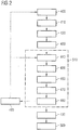
- Fig. 2 is a flowchart illustrating the operation of the multi-fuel power plant with different types of fuels.
- the present disclosure may be based in part on the realization that the operation of ICEs with alternative fuels should not be affected by the specific features of the alternative fuel. For example, corrosive activity may be limited by temporally limiting the contact of a surface with a pyrolysis based fuel as much as possible. With respect to the incompatibility between crude oil based fuels and alternative fuels, the contact of those fuels may be avoided or reduced as far as possible because, when a pyrolysis oil based fuel is contacted with a mineral oilbased fuel, the mutual incompatibility may cause a precipitation phenomenon. The resulting precipitates may obstruct filters, valves, ducts, and pipes of the ICE and associated systems and, thus, may require extensive cleaning operation, accompanied by costly downtime of the ICE and the associated systems.
- the ability to switching between fuels during continuous operation may allow starting an ICE with a cleaning fuel as the ICE may not be started with pyrolysis oil directly.
- the cleaning fuel the ICE may be brought to a temperature needed for alternative fuel operation, for example, pyrolysis based fuel operation.
- the ICE may be started with a crude oil based fuel and brought to temperature. Then, using an intermediary switch over fuel, one may switch to alternative fuel operation, for example, pyrolysis based fuel operation.
- a switch over process may apply the cleaning fuel as a switch over fuel, thereby at least largely avoiding any mixing of crude oil based fuel and, for example, pyrolysis oil based fuel and a polymerization effect and precipitation phenomenon caused by such a mixing, which may block valves, injectors, equipments, and piping of the engine system.
- the switch over process may further allow increasing the temperature level of the ICE during a heating phase to a temperature needed for pyrolysis oil based fuel operation.
- a power plant 1 may include a power house 10, a tank farm 20, and a fuel treatment building 30.
- Power house 10 may include one or more ICEs 100 and, for one or more ICEs 100, a conditioning/circulating system 110 including a conditioning unit 112, a fuel recirculating unit 114, and a first switching unit 116 and a second switching unit 118.
- Conditioning unit 112 may comprise alternative fuel conditioning sections 112A, cleaning fuel conditioning section 112B, and crude oil based fuel condition section 112C for the different types of fuel that may need conditioning prior being supplied to ICE 100.
- Tank farm 20 may include various tank sections.
- tank farm 20 may include an alternative fuel tank section 210 for tanks for alternative fuels such as a pyrolysis oil based fuel tank 212.
- Tank farm 20 may further include a cleaning fuel tank section 220 for tanks for the cleaning fuels or components for the cleaning fuel such as, for example, a caster oil tank 222 and an ethanol tank 224 for a switching fuel.
- a cleaning fuel tank section 220 for tanks for the cleaning fuels or components for the cleaning fuel such as, for example, a caster oil tank 222 and an ethanol tank 224 for a switching fuel.
- Tank farm 20 may further include a crude oil based fuel tank section 230 for tanks for crude oil based fuels such as, for example, a Diesel fuel tank 232 and an HFO tank 234.
- a crude oil based fuel tank section 230 for tanks for crude oil based fuels such as, for example, a Diesel fuel tank 232 and an HFO tank 234.
- tank farm 20 may include a waste tank section 240 including an HFO waste tank 242 for receiving waste of the HFO treatment process explained below and a Diesel fuel/cleaning fuel waste tank 244 for receiving waste fuel generated during the switching between Diesel fuel operation and cleaning fuel operation.
- a waste tank section 240 including an HFO waste tank 242 for receiving waste of the HFO treatment process explained below and a Diesel fuel/cleaning fuel waste tank 244 for receiving waste fuel generated during the switching between Diesel fuel operation and cleaning fuel operation.
- the cleaning fuel may be an ethanol-based fuel that may include besides ethanol additional components, for example, a bio-oil such as castor oil and optionally some additives.
- an ethanol-based fuel may consist of, based on the total volume of ethanol and castor oil, 20 to 90 % by volume ethanol and 80 to 10 % by volume castor oil (in particular 40 to 90 % by volume ethanol and 60 to 10 % by volume castor oil), and optionally including one or more additives in a total amount of up to 3 wt.-% of the total weight of the ethanol and castor oil.
- the ethanol may be from biological sources.
- ethanol as used herein and in the appended claims comprises both absolute ethanol (i.e. ethanol containing less than 2 % by volume (for example, less than 0,5 % by volume) water) and ethanol containing considerable amounts of water.
- castor oil may be used in the present ethanol-based fuel.
- Caster oil is a vegetable oil obtained from castor seed of the castor plant Ricinus communis.
- Ricinoleic acid which is the main fatty acid chain of castor oil (85 to 95 wt.-%), has a hydroxyl group at C 12 , which provides the fatty acid chain with polar properties, promoting solubility in polar liquids like ethanol.
- the remaining non-polar hydrocarbon chain of ricinoleic acid still provides sufficient non-polar character such that castor oil is miscible with non-polar liquids, like, for example, crude oil based fuels such as diesel fuel, LFO or HFO.
- the ethanol content may be 40 to 80 % by volume (e.g. 45 to 65 % by volume or 45 to 55 % by volume or 48 to 52 % by volume) and the castor oil content is 60 to 20 % by volume (e.g. 55 to 35 % by volume or 55 to 45 % by volume or 52 to 48 % by volume).
- the ethanol content of the ethanol-based fuel may be as high as possible, for example, 60 to 90 % by volume, or 70 to 90 % by volume, or 80 to 90 % by volume or 85 to 90 % by volume, in case the ethanol-based fuel is to be used for continuous (long-time) operation of an ICE, in particular a self-ignition ICE.
- the ethanol-based fuel may optionally include one or more additives, for example, in a total amount of up to 3 wt.-% of the total weight of the ethanol and castor oil, preferably in a total amount of up to 2 wt.-%, in particular in a total amount of up to 1 wt.-% of the total weight of the ethanol and castor oil.
- Said additives may be selected from the group of additives consisting of thermal stabilizers, aging stabilizers, antioxidants, coloring agents, dyes, rust inhibitors, inhibitors of gum formation, metal deactivators, upper cylinder lubricants, friction modifiers, detergents, bacteriostatic agents, fungicides, microbiocides, and mixtures thereof.
- the additives optionally included in the ethanol-based fuel may serve to improve one or more properties of the ethanol-based fuel, if considered to be necessary in view of the used engine type or any other circumstances, which require the use of additives. However, in view of environmental concerns (increased emissions), the ethanol-based fuel may be provided devoid of any additives.
- Multi-fuel power plant 1 may be operated only with the cleaning fuel and an alternative fuel. In that case, the configuration shown in Fig. 1 would simplify accordingly. Specifically, crude oil based fuel tank section 230 may not need to be provided and also treatment building 30 and conditioning/circulating system 110 may be simplified accordingly, as will be apparent to the person skilled in the art.
- Treatment building 30 may include one or more treatment units for the various fuels.
- treatment building 30 may include an alternative fuel treatment unit 310 for alternative fuels that may be fluidly connected to pyrolysis oil based fuel tank 212.
- alternative fuel treatment unit 310 may include a centrifuge for extracting small size particles.
- alternative fuel treatment unit 310 may be fluidly connected to alternative fuel conditioning section 112A of conditioning unit 112.
- Treatment building 30 may further include a cleaning fuel treatment unit 320 fluidly connected to tanks for the cleaning fuel or its components.
- a cleaning fuel treatment unit 320 fluidly connected to tanks for the cleaning fuel or its components.
- caster oil tank 222 and ethanol tank 224 may be each fluidly connected to cleaning fuel treatment unit 320.
- the ethanol and the caster oil may be mixed together and filtered.
- caster oil tank 222 and ethanol tank 224 may be combined in the required ratio before being supplied as cleaning fuel to cleaning fuel treatment unit 320, where then only filtering may take place.
- the cleaning fuel may be provided to alternative fuel treatment unit 310 via a flushing connection 322, which may be fluidly connected to a pipe system within alternative fuel treatment unit 310 carrying the cleaning fuel or the ethanol only.
- flushing connection 322 is shown in Fig. 1 to be connected to a cleaning fuel pipe 324 via a cleaning fuel valve 326.
- Cleaning fuel pipe 324 may fluidly connect alternative fuel treatment unit 310 with conditioning unit 112, for example, with cleaning fuel conditioning section 112B of conditioning unit 112.
- ethanol tank 224 may be additionally fluidly connected to alternative fuel conditioning section 112A of conditioning unit 112 via a by-pass fuel pipe 327.
- Diesel fuel tank 232 may be fluidly connected to crude oil based fuel conditioning section 112C of conditioning unit 112 via Diesel fuel pipe 328 with or without passing any treatment unit.
- Treatment building 30 may further include a HFO treatment unit 330 fluidly connected to HFO tank 234 for cleaning the HFO, for example, via a centrifuge based system. Waste from the cleaning process may be supplied to HFO waste tank via HFO waste line 332. In addition, filtered HFO fuel may be returned to HFO tank 234 via HFO return line 334 in case more HFO is cleaned than be needed for operating ICE 100.
- a HFO valve 336 may be used to control the amount of HFO returned to HFO tank 234 and the amount of HFO provided to crude oil based fuel conditioning section 112C of conditioning unit 112 via HFO line 338.
- fuel connection lines 340 between the tanks of tank farm 20 and the respective treatment units may include pumps, control valves, pressure sensors, and/or temperature sensors (not shown).
- the tanks and the treatment units may be fluidly connected to more than one condition unit 112.
- Fig. 1 illustrates only a single conditioning unit 112 and a single ICE 100.
- conditioning unit 112 may comprise a fuel selection valve 113 fluidly connected to each of alternative fuel conditioning section 112A, cleaning fuel conditioning section 112B, and crude oil based fuel condition section 112C as well as fuel recirculating unit 114.
- Conditioning unit 112 may be configured to bring the various fuels to the needed temperature to ensure the required viscosity of the fuel when provided to ICE 100.
- a viscosity sensor 120 may be provided prior ICE 100 as well as various temperature sensors (not shown) may be provided within the power house 10. These components may be used, for example, to control a heat exchanger 123 arranged upstream of viscosity sensor 120.
- Fuel recirculating unit 114 of conditioning/circulating system 110 may be configured for supplying an engine fuel system 121 of ICE 100 with fuel.
- Fuel recirculating unit 114 may comprise a circulation tank 122 and a fuel cooling unit 124.
- Circulation tank 122 may be fluidly connected with fuel conditioning unit 112 and via viscosity sensor 120 with engine fuel system 121.
- Circulation tank 122 may be refilled with the respective fuel from conditioning unit 112 to compensate for the fuel combusted by ICE 100.
- unused fuel may be returned to circulation tank 122.
- the returned unused fuel may be cooled by fuel cooling unit 124, if required.
- a fuel recirculating cycle may comprise, starting at viscosity sensor 120, engine fuel system 121, circulation fuel cooling unit 124, tank 122, and heat exchanger 123.
- a valve unit 126 may be provided in the fuel recirculating cycle to allow releasing unused fuel from the fuel recirculating cycle and stopping any backflow of unused fuel to circulation tank 122. Accordingly, circulation tank will be refilled essentially only by conditioning unit 112. Thus, in case of changing the type of fuel, releasing the fuel via valve unit 126 may accelerate emptying the fuel recirculating cylce with the earlier provided fuel. Partly or completely closing valve unit 126 may then allow cleaning the fuel recirculating cycle, in particular, the components of fuel recirculating unit 114 from the previously provided fuel as will be explained below.
- valve unit 126 may optionally be connected to first switching unit 116 and/or second switching unit 118 to allow faster switching between fuel types.
- multi-fuel power plant 1 may be operated only with the cleaning fuel and an alternative fuel. Then, second switching unit 118 may not be provided and tank farm 20 may not include crude oil based fuel section 230, treatment building may not include HFO treatment unit 330, and condition unit 112 may not include crude oil based fuel conditioning section 112C.
- Each of first switching unit 116 and second switching unit 118 may include a switch over tank 128 and a switch over pump 130, wherein switch over tanks 128 may be fluidly connected to outlets of valve unit 126 via separate switch over lines 132 and 134.
- Providing two separate switch over lines 132, 134 allows providing separate fuel systems for a pyrolysis oil/cleaning fuel mixture as well as crude oil based fuel/ cleaning fuel mixture, e.g. a Diesel fuel/ cleaning fuel mixture.
- a pyrolysis oil/cleaning fuel mixture may be returned to pyrolysis oil based fuel tank 212 via first switch over unit 116 and a Diesel fuel/ cleaning fuel mixture may be directed to Diesel fuel/cleaning fuel waste tank 244 via second switch over unit 118.
- Diesel fuel/cleaning fuel waste tank 244 may be connected to additional combustion units for further reuse.
- first switching unit 116 may be fluidly connected to alternative fuel conditioning sections 112A to be reused during a switching process, for example, controlled via a reuse valve 136.
- the operation of multi-fuel power plant 1 may be controlled by a control system.
- the control system may be configured to control operation of ICE 100 based on a required mechanical output.
- the control system may further control the operation with the various types of fuels as well as the switching between the various types of fuels with a continuously operated engine.
- the control system may include a control unit 40 and one or more control sensors such as temperature sensors (not shown), pressure sensors (not shown), and fluid viscosity sensors, for example, viscosity sensor 120.
- the control sensors may be configured to measure, for example, the temperature and the pressure of the charge air and the exhaust gas at the various pressure stages as well as the temperature, viscosity, and/or pressure of the fuel in treatment building 30, conditioning/circulating system 110, engine fuel system 121, and an injection system of ICE 100 and provide those data to control unit 40.
- Control unit 40 may be a single microprocessor or plural microprocessors that may include means for controlling, among others, an operation of the various components of power plant system 1, for example, valve unit 126, cleaning fuel valve 326, HFO valve 336, fuel selection valve 113, and heat exchanger 123.
- Control unit 40 may be a general engine control unit (ECU) capable of controlling numeral functions associated with power plant system 1 and/or its associated components such as ICE 100.
- Control unit 40 may include all the components required to run an application such as, for example, a memory, a secondary storage device, and a processor such as a central processing unit or any other means known in the art for controlling power plant system 1 and its various components.
- ECU engine control unit
- Control unit 40 may analyze and compare received and stored data, and, based on instructions and data stored in memory or input by a user, determine whether action is required. For example, control unit 40 may compare received values with target values stored in memory, and based on the results of the comparison, control unit 40 may transmit signals to one or more components to alter the operation status thereof.
- Control unit 40 may include any memory device known in the art for storing data relating to operation of the combustion engine and its components.
- the data may be stored in the form of one or more maps that describe and/or relate, for example, injection timing.
- Each of the maps may be in the form of tables, graphs, and/or equations, and include a compilation of data collected from lab and/or field operation of the combustion engine.
- the maps may be generated by performing instrumented tests on the operation of the combustion engine under various operating conditions while varying parameters associated therewith. The controller may reference these maps and control operation of one component in response to the desired operation of another component.
- control unit 40 may be configured to receive inputs from the various control sensors. Using the inputs from the control sensors, control unit 40 may be configured to control - via control connections lines 42 (indicated as dotted lines in Fig. 1 ) - the operation of ICE 100, conditioning unit 112, viscosity sensor 120, fuel cooling unit 124, valve unit 126, switch over pumps 130, reuse valve 136, alternative fuel treatment unit 310, cleaning fuel treatment unit 320, cleaning fuel valve 326, HFO treatment unit 330, HFO valve 336, fuel selection valve 113, and heat exchanger 123.
- control connections lines 42 indicated as dotted lines in Fig. 1
- control unit 40 may be configured to control - via control connections lines 42 (indicated as dotted lines in Fig. 1 ) - the operation of ICE 100, conditioning unit 112, viscosity sensor 120, fuel cooling unit 124, valve unit 126, switch over pumps 130, reuse valve 136, alternative fuel treatment unit 310, cleaning fuel treatment unit 320, cleaning fuel valve 326, HFO
- a multi-fuel power system may comprise a tank farm comprising at least one crude oil based fuel tank and at least one alternative fuel tank, a fuel treatment system comprising a crude oil based fuel treatment plant fluidly connected to the at least one crude oil based fuel tank and an alternative fuel treatment plant fluidly connected to the at least one alternative fuel tank; and at least one engine unit comprising an internal combustion engine and a fuel control module, the fuel control module comprising a fuel conditioning unit fluidly connected to the crude oil based fuel treatment plant and the alternative fuel treatment plant, a fuel recirculating system with a circulating tank, which is fluidly connected to the fuel conditioning unit and the internal combustion engine, and a fuel cooling unit, which is fluidly connected to the internal combustion engine via a valve unit and the circulating tank for providing a fuel engine cycle, a first switching unit comprising a first switch over tank fluidly connected to the valve unit and a first switching pump fluidly connected to the first switch over tank and at least one of the alternative fuel tank and the fuel conditioning unit, a second switching unit comprising a first
- the engine may be configured to operate in a self-igniting mode for crude oil based fuel and alternative fuel.
- the tank farm may comprise a switch over fuel tank that is fluidly connected to the alternative fuel treatment plant.
- the crude oil based fuel treatment plant, the alternative fuel treatment plant, and the conditioning unit may be configured to heat the respective fuel to its required temperature, thereby providing the required viscosity.
- the multi-fuel power system may further comprise a viscosity sensor provided in the fluid connection between the circulating tank and the internal combustion engine; and a control unit configured to receive viscosity data of the fluid and to control the heating of at least one of the crude oil based fuel treatment plant, the alternative fuel treatment plant, and the conditioning unit.
- An exemplary switch over process from HFO operation to pyrolysis oil operation may include the following steps that may be performed while the ICE 100 may be continuously operated.
- Operating ICE 100 with cleaning fuel only may correspond essentially to step 440 summarized above.
- Operating ICE 100 with crude oil based fuel only may be based essentially on steps 400 to 420 as summarized above.
- control unit 40 may control the operation parameters of the multi-fuel power plant 100 such as fuel viscosity, fuel temperature, fuel pressure, and fuel injection timing by controlling the various components of the multi-fuel power plant 100 in accordance with the various operating conditions associated with the respective fuels.
- the switching time of step 430 and step 450 may be optimized, for example, by reducing the time period during which ICE 100 may be operated with cleaning fuel only. Additionally, the switching time may be influenced by how much one either burns any unused fuel mixture (fuel recirculating cycle closed) or provides those fuel mixtures directly to the switching tanks 128 (fuel recirculating cycle opened).
- Step 400 to step 500 illustrated above relate to a switching process between crude oil based fuel operation and alternative fuel operation wherein crude oil based fuel operation may be used to start the multi-fuel power plant.
- the cleaning fuel may be used to clean the fuel recirculating cycle inbetween crude oil based fuel operation and alternative fuel operation such that any contact of alternative fuel and crude oil based fuel may be avoided or at least be reduced to an acceptable degree.
- the cleaning fuel may refer to the cleaning fuel as a switch over fuel.
- ICE 100 may be stopped (step 485).
- Restarting ICE 100 may then be performed at step 400 or at step 440, for example.
- the stop and start up process is indicated by dotted lines.
- the cleaning fuel may be used to start the multi-fuel power plant, for example, to perform the warm up process of ICE 100. In that case, there may be no switching between crude oil based fuel operation and alternative fuel operation. Accordingly, an exemplary operation of multi-fuel power plant 100 may be based on step 440 to step 480 only (indicated by a dashed box 510 in Fig. 2 ) whereby those steps may be performed while the ICE 100 may be continuously operated.
- An exemplary multi-fuel power plant for cleaning fuel / alternative fuel operation may not include those components shown in Fig. 1 that relate to crude oil based fuel operation, for example, switch over unit 118, switch over line 134, crude oil based tank section 230, HFO treatment plant 330.
- a method for switching between alternative fuel operation and crude oil based fuel operation of a multi-fuel internal combustion engine may comprise supplying the crude oil based fuel to a recirculation system of an ICE and recirculating uninjected crude oil based fuel within the recirculation system, switching to operating the ICE with a switch over fuel by supplying the switch over fuel to the recirculation system, operating the ICE with the switch over fuel until the recirculation system comprises essentially only the switch over fuel, and switching to operating the ICE with the alternative fuel by supplying the alternative fuel to the recirculation system, thereby recirculating uninjected alternative fuel within the recirculation system.
- the method may further comprise opening the recirculation system when operating the ICE with the switch over fuel, and releasing an uninjected fuel mixture of crude oil based fuel and switch over fuel into a crude oil based fuel/switch over fuel tank, until the crude oil based fuel has reached a predetermined portion in the uninjected fuel mixture of crude oil based fuel and switch over fuel.
- the method may further comprise closing the recirculation system, recirculating uninjected fuel mixture through the recirculation system; and reducing the crude oil based fuel portion from the uninjected fuel mixture by supplying only switch over fuel.
- the method may further comprise, when recirculating uninjected switch over fuel, reopening the recirculation system at least partly, thereby accelerating the removing of the crude oil based fuel from the recirculation system.
- the method may further comprise opening the recirculation system when operating the engine with the alternative fuel, and releasing an uninjected fuel mixture of switch over fuel and alternative fuel into a alternative fuel/switch over fuel tank until the switch over fuel reached a predetermined portion within the uninjected fuel mixture of the switch over fuel and the alternative fuel.
- the method may further comprise closing the recirculation system, recirculating uninjected fuel mixture through the recirculation system, and reducing the switch over fuel portion from the uninjected fuel mixture by supplying only alternative fuel.
- the method may further comprise, when recirculating uninjected switch over fuel, reopening the recirculation system at least partly, thereby accelerating the removing of the crude oil based fuel from the recirculation system.
- the method may further comprise, when operating the internal combustion engine with the switch over fuel, changing the fuel temperature to a temperature close to the successively supplied fuel.
- the method may further comprise switching back to operating the engine with switching fuel SF.
- the method may further comprise, wherein the switch over fuel may be chemical inactive with the alternative fuel and the crude oil based fuel
- internal combustion engine/ICE may refer to internal combustion engines which may be used as main or auxiliary engines of stationary power providing systems such as power plants for production of heat and/or electricity as well as in ships/vessels such as cruiser liners, cargo ships, container ships, and tankers.
- internal combustion engine/ICE as used herein is not specifically restricted and may comprises any engine, in which the combustion of a fuel occurs with an oxidizer to produce high temperature and pressure gases, which are directly applied to a movable component of ICE, such as pistons or turbine blades, and move it over a distance thereby generating mechanical energy.
- ICE internal combustion engine
- the term “internal combustion engine” comprises piston engines and turbines, which can, for example, be operated with alternative fuels such as pyrolysis oil.
- the ICE may be self-ignition based engines.
- the herein disclosed procedure may simplify pyrolysis oil applications and may be used, for example, in Caterpillar engine applications.
Abstract
Description
- The present disclosure generally refers to operating an internal combustion engine (ICE) with multiple fuels and particularly to operating the ICE with alternative fuels such as pyrolysis oil. Moreover, the present disclosure refers to switching an ICE back and forth between pyrolysis oil based fuel operation and crude oil based fuel operation.
- Alternative fuels replacing crude oil based fuels are the subject of ongoing interest, in particular with respect to the replacement of crude oil based fuels such as diesel fuel, light fuel oil (LFO), and heavy fuel oil (HFO). Alternative fuels include first generation biofuels (e.g. palm oil, rapeseed oil, canola oil, oils based on animal fat) and second generation biofuels (e.g. oils made of non food corps, i.e. waste biomass).
- Examples of second generation biofuel include "pyrolysis oils" obtained from the pyrolysis of, for example, wood or agricultural wastes, such as the stalks of wheat or corn, grass, wood, wood shavings, grapes, and sugar cane. In general, pyrolysis oil is predominantly produced by the "Fast pyrolysis" technology, which comprises rapid pyrolysation of biomass in a fluidized bubbling sand bed reactor, wherein the solid heat-carrying medium is circulated and, therefore, the residence time of solids is well-controlled and high heating rates (up to 1000 °C/second) are obtained.
- The chemical composition and the physical properties of alternative fuels such as pyrolysis oil based fuels can differ significantly from those of crude oil based fuels such as diesel fuel, LFO, and HFO, in particular with respect to the high content of water and oxygen, and the acidic value. Moreover, as pyrolysis oils include polar hydrocarbons and large amounts of water, they are almost immiscible with crude oil based fuels, which consist mainly of saturated olefinic and aromatic hydrocarbons. Finally, the acidic value of pyrolysis oil based fuels results in strong corrosion acting on contacted metal parts in engine systems.
- Accordingly, the use of alternative fuels may require an adaptation of ICEs to those specific features of alternative fuels. This may in particular be the case for large ICEs operated at medium speed. A proposal of self-ignition ICEs for operation with alternative fuels is disclosed in the application "SELF IGNITION OPERATION OF ALTERNATIVE FUEL INTERNAL COMBUSTION ENGINES" filed on the same day by Caterpillar Motoren GmbH & Co. KG. The content of the application is herein incorporated by reference.
- Moreover, a pyrolysis oil operated ICE using an oxygen enriched atmosphere is disclosed in
GB 2 349 175 A - The present disclosure is directed, at least in part, to improving or overcoming one or more aspects of the related prior art and particularly to simplify the operation of a power plant operating ICEs with alternative fuels such as pyrolysis oil based fuels.
- According to an aspect of the present disclosure, a multi-fuel power plant may comprise a tank system comprising an alternative fuel tank and at least one cleaning fuel tank, a fuel treatment system comprising an alternative fuel treatment unit fluidly connected to the at least one alternative fuel tank and a cleaning fuel treatment unit fluidly connected to the at least one cleaning fuel tank, a fuel conditioning unit fluidly connected to the alternative fuel treatment unit and the cleaning fuel treatment unit, an internal combustion engine for operation with the alternative fuel and the cleaning fuel, the internal combustion engine comprising an engine fuel system, a fuel recirculating unit for supplying the engine fuel system with fuel, the fuel recirculating unit comprising a circulation tank, which is fluidly connected to the fuel conditioning unit and the engine fuel system, and a control unit configured to control the fuel conditioning unit to condition the fuel selected for being provided to the engine fuel system and to providing the same to the circulation tank, thereby allowing switching between alternative fuel operation and cleaning fuel operation while continuously operating the internal combustion engine.
- According to another aspect of the present disclosure, a method for operating a multi-fuel internal combustion engine configured for alternative fuel operation and cleaning fuel operation, the internal combustion engine comprising a fuel recirculation system with an engine fuel system may comprise providing a cleaning fuel that is chemically compatible to the alternative fuel and allows operation of the internal combustion engine, operating the internal combustion engine with the cleaning fuel such that the fuel recirculation system is filled essentially with the cleaning fuel, during continuous operation of the internal combustion engine, switching to operating the internal combustion engine with the alternative fuel by supplying the alternative fuel to the fuel recirculation system, thereby increasing the ratio of alternative fuel in the engine fuel system.
- According to another aspect of the present disclosure, a method for switching between alternative fuel operation and crude oil based fuel operation of a multi-fuel internal combustion engine with an engine fuel system may comprise operating the internal combustion engine with a crude oil based fuel such that the fuel recirculation system is filled essentially with the crude oil based fuel, during continuous operation of the internal combustion engine, switching to operating the internal combustion engine with a switching fuel, which is chemically compatible to the crude oil based fuel as well as an alternative fuel and allows operation of the internal combustion engine, by supplying the cleaning fuel to the fuel recirculation system, thereby increasing the ratio of the switching fuel in the engine fuel system; and performing the method described above, whereby the switching fuel is provided as the cleaning fuel.
- In some embodiments, the multi-fuel power plant may further comprise a valve unit at an exit of the engine fuel system, and a first switching unit comprising a first switch over tank fluidly connected to the valve unit and a first switching pump fluidly connected to the first switch over tank and at least one of the alternative fuel tank and the fuel conditioning unit, and wherein the control unit is further configured to control the valve unit during a switch over process between alternative fuel operation and cleaning fuel operation to release a fuel mixture comprising cleaning fuel and alternative fuel from the fuel recirculating unit to the first switch over tank.
- Other features and aspects of this disclosure will be apparent from the following description and the accompanying drawings.
-
Fig. 1 shows a schematic block diagram of a multi-fuel power plant; andFig. 2 is a flowchart illustrating the operation of the multi-fuel power plant with different types of fuels. - The following is a detailed description of exemplary embodiments of the present disclosure. The exemplary embodiments described therein and illustrated in the drawings are intended to teach the principles of the present disclosure, enabling those of ordinary skill in the art to implement and use the present disclosure in many different environments and for many different applications. Therefore, the exemplary embodiments are not intended to be, and should not be considered as, a limiting description of the scope of patent protection. Rather, the scope of patent protection shall be defined by the appended claims.
- The present disclosure may be based in part on the realization that the operation of ICEs with alternative fuels should not be affected by the specific features of the alternative fuel. For example, corrosive activity may be limited by temporally limiting the contact of a surface with a pyrolysis based fuel as much as possible. With respect to the incompatibility between crude oil based fuels and alternative fuels, the contact of those fuels may be avoided or reduced as far as possible because, when a pyrolysis oil based fuel is contacted with a mineral oilbased fuel, the mutual incompatibility may cause a precipitation phenomenon. The resulting precipitates may obstruct filters, valves, ducts, and pipes of the ICE and associated systems and, thus, may require extensive cleaning operation, accompanied by costly downtime of the ICE and the associated systems.
- To provide a workable power plant using one or more ICEs operated inter alia with alternative fuels and nevertheless providing power efficiently, those adverse effects may be avoided or at least reduced when continuously operating the ICE in line with the herein proposed concept.
- The ability to switching between fuels during continuous operation may allow starting an ICE with a cleaning fuel as the ICE may not be started with pyrolysis oil directly. Using the cleaning fuel, the ICE may be brought to a temperature needed for alternative fuel operation, for example, pyrolysis based fuel operation.
- Alternatively, the ICE may be started with a crude oil based fuel and brought to temperature. Then, using an intermediary switch over fuel, one may switch to alternative fuel operation, for example, pyrolysis based fuel operation. Such a switch over process may apply the cleaning fuel as a switch over fuel, thereby at least largely avoiding any mixing of crude oil based fuel and, for example, pyrolysis oil based fuel and a polymerization effect and precipitation phenomenon caused by such a mixing, which may block valves, injectors, equipments, and piping of the engine system.
- The switch over process may further allow increasing the temperature level of the ICE during a heating phase to a temperature needed for pyrolysis oil based fuel operation.
- Referring to
Fig. 1 , apower plant 1 may include apower house 10, atank farm 20, and afuel treatment building 30. -
Power house 10 may include one ormore ICEs 100 and, for one ormore ICEs 100, a conditioning/circulatingsystem 110 including aconditioning unit 112, a fuel recirculatingunit 114, and afirst switching unit 116 and asecond switching unit 118.Conditioning unit 112 may comprise alternativefuel conditioning sections 112A, cleaning fuel conditioning section 112B, and crude oil basedfuel condition section 112C for the different types of fuel that may need conditioning prior being supplied to ICE 100. -
Tank farm 20 may include various tank sections. For example,tank farm 20 may include an alternativefuel tank section 210 for tanks for alternative fuels such as a pyrolysis oil basedfuel tank 212. -
Tank farm 20 may further include a cleaningfuel tank section 220 for tanks for the cleaning fuels or components for the cleaning fuel such as, for example, acaster oil tank 222 and anethanol tank 224 for a switching fuel. -
Tank farm 20 may further include a crude oil basedfuel tank section 230 for tanks for crude oil based fuels such as, for example, aDiesel fuel tank 232 and anHFO tank 234. - In addition,
tank farm 20 may include awaste tank section 240 including anHFO waste tank 242 for receiving waste of the HFO treatment process explained below and a Diesel fuel/cleaningfuel waste tank 244 for receiving waste fuel generated during the switching between Diesel fuel operation and cleaning fuel operation. - With respect to cleaning
fuel section 220, tanks for various components of the cleaning fuel may be provided. The cleaning fuel may be an ethanol-based fuel that may include besides ethanol additional components, for example, a bio-oil such as castor oil and optionally some additives. - For example, an ethanol-based fuel may consist of, based on the total volume of ethanol and castor oil, 20 to 90 % by volume ethanol and 80 to 10 % by volume castor oil (in particular 40 to 90 % by volume ethanol and 60 to 10 % by volume castor oil), and optionally including one or more additives in a total amount of up to 3 wt.-% of the total weight of the ethanol and castor oil.
- The ethanol may be from biological sources. The term "ethanol" as used herein and in the appended claims comprises both absolute ethanol (i.e. ethanol containing less than 2 % by volume (for example, less than 0,5 % by volume) water) and ethanol containing considerable amounts of water.
- As a bio-oil, castor oil may be used in the present ethanol-based fuel. Caster oil is a vegetable oil obtained from castor seed of the castor plant Ricinus communis. Ricinoleic acid, which is the main fatty acid chain of castor oil (85 to 95 wt.-%), has a hydroxyl group at C12, which provides the fatty acid chain with polar properties, promoting solubility in polar liquids like ethanol. At the same time, the remaining non-polar hydrocarbon chain of ricinoleic acid still provides sufficient non-polar character such that castor oil is miscible with non-polar liquids, like, for example, crude oil based fuels such as diesel fuel, LFO or HFO.
- The ethanol content may be 40 to 80 % by volume (e.g. 45 to 65 % by volume or 45 to 55 % by volume or 48 to 52 % by volume) and the castor oil content is 60 to 20 % by volume (e.g. 55 to 35 % by volume or 55 to 45 % by volume or 52 to 48 % by volume). For economical reasons, the ethanol content of the ethanol-based fuel may be as high as possible, for example, 60 to 90 % by volume, or 70 to 90 % by volume, or 80 to 90 % by volume or 85 to 90 % by volume, in case the ethanol-based fuel is to be used for continuous (long-time) operation of an ICE, in particular a self-ignition ICE.
- The ethanol-based fuel may optionally include one or more additives, for example, in a total amount of up to 3 wt.-% of the total weight of the ethanol and castor oil, preferably in a total amount of up to 2 wt.-%, in particular in a total amount of up to 1 wt.-% of the total weight of the ethanol and castor oil. Said additives may be selected from the group of additives consisting of thermal stabilizers, aging stabilizers, antioxidants, coloring agents, dyes, rust inhibitors, inhibitors of gum formation, metal deactivators, upper cylinder lubricants, friction modifiers, detergents, bacteriostatic agents, fungicides, microbiocides, and mixtures thereof.
- The additives optionally included in the ethanol-based fuel may serve to improve one or more properties of the ethanol-based fuel, if considered to be necessary in view of the used engine type or any other circumstances, which require the use of additives. However, in view of environmental concerns (increased emissions), the ethanol-based fuel may be provided devoid of any additives.
- Further details of an ethanol based fuel are disclosed, for example, in the application "ETHANOL-BASED FUEL AND USE THEREOF" filed on the same day by Caterpillar Motoren GmbH & Co. KG. The content of the application is herein incorporated by reference.
-
Multi-fuel power plant 1 may be operated only with the cleaning fuel and an alternative fuel. In that case, the configuration shown inFig. 1 would simplify accordingly. Specifically, crude oil basedfuel tank section 230 may not need to be provided and alsotreatment building 30 and conditioning/circulatingsystem 110 may be simplified accordingly, as will be apparent to the person skilled in the art. -
Treatment building 30 may include one or more treatment units for the various fuels. For example,treatment building 30 may include an alternativefuel treatment unit 310 for alternative fuels that may be fluidly connected to pyrolysis oil basedfuel tank 212. In the case of a pyrolysis oil based fuel, alternativefuel treatment unit 310 may include a centrifuge for extracting small size particles. Via an alternative fuel pipe 312, alternativefuel treatment unit 310 may be fluidly connected to alternativefuel conditioning section 112A ofconditioning unit 112. -
Treatment building 30 may further include a cleaning fuel treatment unit 320 fluidly connected to tanks for the cleaning fuel or its components. As exemplary shown inFig. 1 ,caster oil tank 222 andethanol tank 224 may be each fluidly connected to cleaning fuel treatment unit 320. In cleaning fuel treatment unit 320, the ethanol and the caster oil may be mixed together and filtered. In some embodiments,caster oil tank 222 andethanol tank 224 may be combined in the required ratio before being supplied as cleaning fuel to cleaning fuel treatment unit 320, where then only filtering may take place. - In some embodiments, the cleaning fuel may be provided to alternative
fuel treatment unit 310 via aflushing connection 322, which may be fluidly connected to a pipe system within alternativefuel treatment unit 310 carrying the cleaning fuel or the ethanol only. For illustrative purposes, flushingconnection 322 is shown inFig. 1 to be connected to a cleaningfuel pipe 324 via a cleaningfuel valve 326. -
Cleaning fuel pipe 324 may fluidly connect alternativefuel treatment unit 310 withconditioning unit 112, for example, with cleaning fuel conditioning section 112B ofconditioning unit 112. - In some embodiments,
ethanol tank 224 may be additionally fluidly connected to alternativefuel conditioning section 112A ofconditioning unit 112 via a by-pass fuel pipe 327. - In some embodiments,
Diesel fuel tank 232 may be fluidly connected to crude oil basedfuel conditioning section 112C ofconditioning unit 112 viaDiesel fuel pipe 328 with or without passing any treatment unit. -
Treatment building 30 may further include aHFO treatment unit 330 fluidly connected toHFO tank 234 for cleaning the HFO, for example, via a centrifuge based system. Waste from the cleaning process may be supplied to HFO waste tank viaHFO waste line 332. In addition, filtered HFO fuel may be returned toHFO tank 234 viaHFO return line 334 in case more HFO is cleaned than be needed for operatingICE 100. AHFO valve 336 may be used to control the amount of HFO returned toHFO tank 234 and the amount of HFO provided to crude oil basedfuel conditioning section 112C ofconditioning unit 112 via HFO line 338. - In general,
fuel connection lines 340 between the tanks oftank farm 20 and the respective treatment units may include pumps, control valves, pressure sensors, and/or temperature sensors (not shown). Moreover, the tanks and the treatment units may be fluidly connected to more than onecondition unit 112. As an example,Fig. 1 illustrates only asingle conditioning unit 112 and asingle ICE 100. - For the selection of what type of fuel from which section of
conditioning unit 112 may be provided toICE 100,conditioning unit 112 may comprise afuel selection valve 113 fluidly connected to each of alternativefuel conditioning section 112A, cleaning fuel conditioning section 112B, and crude oil basedfuel condition section 112C as well asfuel recirculating unit 114. -
Conditioning unit 112 may be configured to bring the various fuels to the needed temperature to ensure the required viscosity of the fuel when provided toICE 100. Aviscosity sensor 120 may be providedprior ICE 100 as well as various temperature sensors (not shown) may be provided within thepower house 10. These components may be used, for example, to control aheat exchanger 123 arranged upstream ofviscosity sensor 120. -
Fuel recirculating unit 114 of conditioning/circulatingsystem 110 may be configured for supplying anengine fuel system 121 ofICE 100 with fuel.Fuel recirculating unit 114 may comprise acirculation tank 122 and afuel cooling unit 124.Circulation tank 122 may be fluidly connected withfuel conditioning unit 112 and viaviscosity sensor 120 withengine fuel system 121. -
Circulation tank 122 may be refilled with the respective fuel fromconditioning unit 112 to compensate for the fuel combusted byICE 100. During stable operation with one type of fuel, unused fuel may be returned tocirculation tank 122. Depending on the type of fuel, the returned unused fuel may be cooled byfuel cooling unit 124, if required. Accordingly, a fuel recirculating cycle may comprise, starting atviscosity sensor 120,engine fuel system 121, circulationfuel cooling unit 124,tank 122, andheat exchanger 123. - A
valve unit 126 may be provided in the fuel recirculating cycle to allow releasing unused fuel from the fuel recirculating cycle and stopping any backflow of unused fuel tocirculation tank 122. Accordingly, circulation tank will be refilled essentially only byconditioning unit 112. Thus, in case of changing the type of fuel, releasing the fuel viavalve unit 126 may accelerate emptying the fuel recirculating cylce with the earlier provided fuel. Partly or completely closingvalve unit 126 may then allow cleaning the fuel recirculating cycle, in particular, the components offuel recirculating unit 114 from the previously provided fuel as will be explained below. - As shown in
Fig. 1 ,valve unit 126 may optionally be connected tofirst switching unit 116 and/orsecond switching unit 118 to allow faster switching between fuel types. - As pointed out above,
multi-fuel power plant 1 may be operated only with the cleaning fuel and an alternative fuel. Then,second switching unit 118 may not be provided andtank farm 20 may not include crude oil basedfuel section 230, treatment building may not includeHFO treatment unit 330, andcondition unit 112 may not include crude oil basedfuel conditioning section 112C. - Each of
first switching unit 116 andsecond switching unit 118 may include a switch overtank 128 and a switch overpump 130, wherein switch overtanks 128 may be fluidly connected to outlets ofvalve unit 126 via separate switch overlines - Providing two separate switch over
lines - For example, a pyrolysis oil/cleaning fuel mixture may be returned to pyrolysis oil based
fuel tank 212 via first switch overunit 116 and a Diesel fuel/ cleaning fuel mixture may be directed to Diesel fuel/cleaningfuel waste tank 244 via second switch overunit 118. Diesel fuel/cleaningfuel waste tank 244 may be connected to additional combustion units for further reuse. - Moreover, an outlet of
first switching unit 116 may be fluidly connected to alternativefuel conditioning sections 112A to be reused during a switching process, for example, controlled via areuse valve 136. - The operation of
multi-fuel power plant 1 may be controlled by a control system. Specifically, the control system may be configured to control operation ofICE 100 based on a required mechanical output. The control system may further control the operation with the various types of fuels as well as the switching between the various types of fuels with a continuously operated engine. - The control system may include a
control unit 40 and one or more control sensors such as temperature sensors (not shown), pressure sensors (not shown), and fluid viscosity sensors, for example,viscosity sensor 120. The control sensors may be configured to measure, for example, the temperature and the pressure of the charge air and the exhaust gas at the various pressure stages as well as the temperature, viscosity, and/or pressure of the fuel intreatment building 30, conditioning/circulatingsystem 110,engine fuel system 121, and an injection system ofICE 100 and provide those data to controlunit 40. -
Control unit 40 may be a single microprocessor or plural microprocessors that may include means for controlling, among others, an operation of the various components ofpower plant system 1, for example,valve unit 126, cleaningfuel valve 326,HFO valve 336,fuel selection valve 113, andheat exchanger 123.Control unit 40 may be a general engine control unit (ECU) capable of controlling numeral functions associated withpower plant system 1 and/or its associated components such asICE 100.Control unit 40 may include all the components required to run an application such as, for example, a memory, a secondary storage device, and a processor such as a central processing unit or any other means known in the art for controllingpower plant system 1 and its various components. - Various other known circuits may be associated with
control unit 40, including power supply circuitry, signal-conditioning circuitry, communication circuitry, and other appropriate circuitry.Control unit 40 may analyze and compare received and stored data, and, based on instructions and data stored in memory or input by a user, determine whether action is required. For example,control unit 40 may compare received values with target values stored in memory, and based on the results of the comparison,control unit 40 may transmit signals to one or more components to alter the operation status thereof. -
Control unit 40 may include any memory device known in the art for storing data relating to operation of the combustion engine and its components. The data may be stored in the form of one or more maps that describe and/or relate, for example, injection timing. Each of the maps may be in the form of tables, graphs, and/or equations, and include a compilation of data collected from lab and/or field operation of the combustion engine. The maps may be generated by performing instrumented tests on the operation of the combustion engine under various operating conditions while varying parameters associated therewith. The controller may reference these maps and control operation of one component in response to the desired operation of another component. - Specifically,
control unit 40 may be configured to receive inputs from the various control sensors. Using the inputs from the control sensors,control unit 40 may be configured to control - via control connections lines 42 (indicated as dotted lines inFig. 1 ) - the operation ofICE 100,conditioning unit 112,viscosity sensor 120,fuel cooling unit 124,valve unit 126, switch overpumps 130,reuse valve 136, alternativefuel treatment unit 310, cleaning fuel treatment unit 320, cleaningfuel valve 326,HFO treatment unit 330,HFO valve 336,fuel selection valve 113, andheat exchanger 123. - In some embodiments, a multi-fuel power system may comprise a tank farm comprising at least one crude oil based fuel tank and at least one alternative fuel tank, a fuel treatment system comprising a crude oil based fuel treatment plant fluidly connected to the at least one crude oil based fuel tank and an alternative fuel treatment plant fluidly connected to the at least one alternative fuel tank; and at least one engine unit comprising an internal combustion engine and a fuel control module, the fuel control module comprising a fuel conditioning unit fluidly connected to the crude oil based fuel treatment plant and the alternative fuel treatment plant, a fuel recirculating system with a circulating tank, which is fluidly connected to the fuel conditioning unit and the internal combustion engine, and a fuel cooling unit, which is fluidly connected to the internal combustion engine via a valve unit and the circulating tank for providing a fuel engine cycle, a first switching unit comprising a first switch over tank fluidly connected to the valve unit and a first switching pump fluidly connected to the first switch over tank and at least one of the alternative fuel tank and the fuel conditioning unit, a second switching unit comprising a second switch over tank fluidly connected to the valve unit and a second switching pump fluidly connected to the second switch and a waste fuel tank. The engine may be configured to operate in a self-igniting mode for crude oil based fuel and alternative fuel. The tank farm may comprise a switch over fuel tank that is fluidly connected to the alternative fuel treatment plant. The crude oil based fuel treatment plant, the alternative fuel treatment plant, and the conditioning unit may be configured to heat the respective fuel to its required temperature, thereby providing the required viscosity. The multi-fuel power system may further comprise a viscosity sensor provided in the fluid connection between the circulating tank and the internal combustion engine; and a control unit configured to receive viscosity data of the fluid and to control the heating of at least one of the crude oil based fuel treatment plant, the alternative fuel treatment plant, and the conditioning unit.
- An exemplary switch over process from HFO operation to pyrolysis oil operation may include the following steps that may be performed while the
ICE 100 may be continuously operated. -
Operating ICE 100 with HFO (step 400): - Crude oil based
fuel treatment unit 330 andconditioning unit section 112C may be configured to ensure the required viscosity of 6-20 cSt by heating the HFO to 150-160 °C. Any unburned HFO is kept within the fuel recirculating cycle. -
Circulation tank 122 may thus be refilled with HFO only. - Switching to operating
ICE 100 with Diesel fuel (step 410): -
Conditioning unit section 112C may be provided with Diesel fuel fromDiesel fuel tank 232. Accordingly,circulation tank 122 may be refilled with Diesel fuel only and the fuel recirculating cycle continuously may be changed to a pure Diesel fuel operation. Thereby, the temperature of common components withinconditioning unit 112 as well as the components of fuel recirculating cycle may be reduced. Conditioning unit may ensure the required viscosity of 2-4 cSt by providing the Diesel fuel at, for example, 18-20 °C. Diesel fuel may in general be provided in a temperature range between 10 °C to 70 °C. -
Operating ICE 100 with Diesel fuel only (step 420): -
Conditioning unit 112C may ensure the required viscosity. Any unburned Diesel fuel may be kept within the fuel recirculating cycle and may be cooled withfuel cooling unit 124. Circulation tank may be refilled with Diesel fuel only. - Switching to operating
ICE 100 with the cleaning fuel (step 430): - Conditioning unit section 112B may be provided with cleaning fuel from cleaning fuel tanks or from cleaning fuel being composed in cleaning fuel treatment unit 320.
Circulation tank 122 may be refilled with cleaning fuel only. - Cleaning fuel treatment unit 320 and conditioning unit 112B may ensure the required viscosity of the cleaning fuel. Initially, the fuel recirculating cycle may be opened via
valve unit 126 and any unburned fuel mixture of Diesel fuel and cleaning may be accumulated within DFO/switch overfuel waste tank 244 using second switch overunit 118. Then,valve unit 126 may close the fuel recirculating cycle such that all of its components may be cleaned from crude oil based fuel remaining by the cleaning fuel such that the fuel recirculating cycle may become essentially free of crude oil based fuel remains. During the cleaning process,valve unit 126 may reconnect Diesel fuel/cleaningfuel waste tank 244 at least partly the outlet ofengine fuel system 121 or for limited periods of time to speed up the cleaning process. -
Operating ICE 100 with cleaning fuel only (step 440): - Cleaning fuel treatment unit 320 and conditioning unit 112B may ensure the required viscosity of 8-20 cSt by providing the cleaning fuel at a temperature within the range of 18-62 °C. Any unburned cleaning fuel may be kept within the fuel recirculating cycle and may be cooled with
fuel cooling unit 124, if required. -
Circulation tank 112 may be refilled with cleaning fuel only. - Switching to operating
ICE 100 with a pyrolysis oil based fuel (step 450): - Alternative
fuel conditioning section 112A may be provided with pyrolysis based fuel fromalternative fuel tank 212 via alternativefuel treatment unit 310. -
Circulation tank 112 may be refilled with pyrolysis oil based fuel. Alternativefuel treatment unit 310 andconditioning unit section 112A may ensure the required viscosity of the pyrolysis oil based fuel. Initially, the fuel recirculating cycle may be opened viavalve unit 126 and any unburned fuel mixture of alternative fuel and cleaning may be accumulated withinswitching tank 128 of first switch overunit 116 and then be returned toconditioning unit section 112A and/oralternative fuel tank 212.Valve unit 126 may close the fuel recirculating cycle such that the alternative fuel/cleaning fuel mixture may be recirculated until - due to the refilling by the alternative fuel only - the fuel recirculating cycle essentially contains only alternative fuel.
-
Operating ICE 100 with pyrolysis oil based fuel only (step 460): - Alternative
fuel treatment unit 310 andconditioning unit section 112A may ensure the required viscosity of, for example, 12-28 cSt by providing the alternative fuel at a temperature within the range of 62-65 °C. Any unburned pyrolysis oil may be kept within the recirculation unit and may be cooled withfuel cooling unit 124, if required.Circulation tank 122 may be refilled with the pyrolysis oil based fuel only. - Switching back to operating
ICE 100 with cleaning fuel (step 470): - It may be switched to refill
circulation tank 122 with cleaning fuel. Initially, fuel recirculating cycle may be decoupled viavalve unit 126 and the unburned fuel mixture of pyrolysis oil based fuel and cleaning fuel may be returned to conditioning unit section 112 (not indicated inFig. 1 ) oralternative fuel tank 212 using first switch overunit 116. Then,valve unit 126 may close fuel recirculating cycle that is refilled with cleaning fuel only such that all components of the fuel recirculating cycle may be cleaned until the fuel recirculating cycle may be essentially free of any pyrolysis oil. During the cleaning process,valve unit 126 may at least be partly reconnected to pyrolysis oil tank 212 (for example, after reconnecting fuel cooling unit 124) to speed up the cleaning process. -
Operating ICE 100 with cleaning fuel only (step 480) may correspond essentially to step 440 summarized above. - Switching back to operating
ICE 100 with crude oil based fuel (step 490): -
Conditioning unit section 112C may be provided with a crude oil based fuel such as Diesel fuel from crude oil basedtank section 230.Circulation tank 122 may be refilled with the crude oil based fuel only. Crude oil based fuel treatment units andconditioning unit 112C may ensure the required viscosity of the crude oil based fuel.Valve unit 126 may be maintained closed such that fuel mixture may be maintained in the fuel recirculating cycle and used to operate the engine. In view of the refilling with crude oil based fuel only, the part of cleaning fuel may continuously decrease. Alternatively, the fuel recirculating cycle may be opened viavalve unit 126 and any unburned fuel mixture of crude oil based fuel and cleaning fuel may be accumulated within Diesel fuel/switch overfuel waste tank 244 via second switch overunit 118. -
Operating ICE 100 with crude oil based fuel only (step 500) may be based essentially onsteps 400 to 420 as summarized above. - During the various steps,
control unit 40 may control the operation parameters of themulti-fuel power plant 100 such as fuel viscosity, fuel temperature, fuel pressure, and fuel injection timing by controlling the various components of themulti-fuel power plant 100 in accordance with the various operating conditions associated with the respective fuels. - The switching time of
step 430 and step 450 may be optimized, for example, by reducing the time period during whichICE 100 may be operated with cleaning fuel only. Additionally, the switching time may be influenced by how much one either burns any unused fuel mixture (fuel recirculating cycle closed) or provides those fuel mixtures directly to the switching tanks 128 (fuel recirculating cycle opened). - Step 400 to step 500 illustrated above relate to a switching process between crude oil based fuel operation and alternative fuel operation wherein crude oil based fuel operation may be used to start the multi-fuel power plant. In that case, the cleaning fuel may be used to clean the fuel recirculating cycle inbetween crude oil based fuel operation and alternative fuel operation such that any contact of alternative fuel and crude oil based fuel may be avoided or at least be reduced to an acceptable degree. For such a switching process, one may refer to the cleaning fuel as a switch over fuel.
- Besides the switching between the fuels, the sequence disclosed above or some parts of it may be applied when turning
ICE 100 off and on. For example, followingstep 480,ICE 100 may be stopped (step 485). RestartingICE 100 may then be performed atstep 400 or atstep 440, for example. InFig. 2 , the stop and start up process is indicated by dotted lines. Thus, the configurations and methods disclosed herein may allow a simple stopping and start up procedure of a power plant for alternative fuels. - In some embodiments, the cleaning fuel may be used to start the multi-fuel power plant, for example, to perform the warm up process of
ICE 100. In that case, there may be no switching between crude oil based fuel operation and alternative fuel operation. Accordingly, an exemplary operation ofmulti-fuel power plant 100 may be based onstep 440 to step 480 only (indicated by a dashedbox 510 inFig. 2 ) whereby those steps may be performed while theICE 100 may be continuously operated. An exemplary multi-fuel power plant for cleaning fuel / alternative fuel operation may not include those components shown inFig. 1 that relate to crude oil based fuel operation, for example, switch overunit 118, switch overline 134, crude oil basedtank section 230,HFO treatment plant 330. - In some embodiments, a method for switching between alternative fuel operation and crude oil based fuel operation of a multi-fuel internal combustion engine may comprise supplying the crude oil based fuel to a recirculation system of an ICE and recirculating uninjected crude oil based fuel within the recirculation system, switching to operating the ICE with a switch over fuel by supplying the switch over fuel to the recirculation system, operating the ICE with the switch over fuel until the recirculation system comprises essentially only the switch over fuel, and switching to operating the ICE with the alternative fuel by supplying the alternative fuel to the recirculation system, thereby recirculating uninjected alternative fuel within the recirculation system.
- In some embodiments, the method may further comprise opening the recirculation system when operating the ICE with the switch over fuel, and releasing an uninjected fuel mixture of crude oil based fuel and switch over fuel into a crude oil based fuel/switch over fuel tank, until the crude oil based fuel has reached a predetermined portion in the uninjected fuel mixture of crude oil based fuel and switch over fuel.
- In some embodiments, the method may further comprise closing the recirculation system, recirculating uninjected fuel mixture through the recirculation system; and reducing the crude oil based fuel portion from the uninjected fuel mixture by supplying only switch over fuel.
- In some embodiments, the method may further comprise, when recirculating uninjected switch over fuel, reopening the recirculation system at least partly, thereby accelerating the removing of the crude oil based fuel from the recirculation system.
- In some embodiments, the method may further comprise opening the recirculation system when operating the engine with the alternative fuel, and releasing an uninjected fuel mixture of switch over fuel and alternative fuel into a alternative fuel/switch over fuel tank until the switch over fuel reached a predetermined portion within the uninjected fuel mixture of the switch over fuel and the alternative fuel.
- In some embodiments, the method may further comprise closing the recirculation system, recirculating uninjected fuel mixture through the recirculation system, and reducing the switch over fuel portion from the uninjected fuel mixture by supplying only alternative fuel.
- In some embodiments, the method may further comprise, when recirculating uninjected switch over fuel, reopening the recirculation system at least partly, thereby accelerating the removing of the crude oil based fuel from the recirculation system.
- In some embodiments, the method may further comprise, when operating the internal combustion engine with the switch over fuel, changing the fuel temperature to a temperature close to the successively supplied fuel.
- In some embodiments, the method may further comprise switching back to operating the engine with switching fuel SF.
- In some embodiments, the method may further comprise, wherein the switch over fuel may be chemical inactive with the alternative fuel and the crude oil based fuel
- Herein, the term "internal combustion engine/ICE" may refer to internal combustion engines which may be used as main or auxiliary engines of stationary power providing systems such as power plants for production of heat and/or electricity as well as in ships/vessels such as cruiser liners, cargo ships, container ships, and tankers.
- In addition, the term "internal combustion engine/ICE" as used herein is not specifically restricted and may comprises any engine, in which the combustion of a fuel occurs with an oxidizer to produce high temperature and pressure gases, which are directly applied to a movable component of ICE, such as pistons or turbine blades, and move it over a distance thereby generating mechanical energy. Thus, as used herein, the term "internal combustion engine" comprises piston engines and turbines, which can, for example, be operated with alternative fuels such as pyrolysis oil. The ICE may be self-ignition based engines.
- The herein disclosed procedure may simplify pyrolysis oil applications and may be used, for example, in Caterpillar engine applications. Examples of such engines that are suitable for adaptation to alternative fuels include medium speed internal combustion diesel engines, like inline and V-type engines of the series M20, M25, M32, M43 manufactured by Caterpillar Motoren GmbH & Co. KG, Kiel, Germany, operated in a range of 500 to 1000 rpm.
- Although the preferred embodiments of this invention have been described herein, improvements and modifications may be incorporated without departing from the scope of the following claims.
Claims (15)
- A multi-fuel power plant (1) comprising:a tank system (20) comprising an alternative fuel tank (212) and at least one cleaning fuel tank (222, 224);a fuel treatment system (30) comprising an alternative fuel treatment unit (310) fluidly connected to the at least one alternative fuel tank (212) and a cleaning fuel treatment unit (320) fluidly connected to the at least one cleaning fuel tank (222, 224);a fuel conditioning unit (112) fluidly connected to the alternative fuel treatment unit (310) and the cleaning fuel treatment unit (320);an internal combustion engine (100) for operation with the alternative fuel and the cleaning fuel, the internal combustion engine (100) comprising an engine fuel system (121);a fuel recirculating unit (114) for supplying the engine fuel system (121) with fuel, the fuel recirculating unit (114) comprising a circulation tank (122), which is fluidly connected to the fuel conditioning unit (112) and the engine fuel system (121); anda control unit (40) configured to control the fuel conditioning unit (112) to condition the fuel selected for being provided to the engine fuel system (121) and to provide the same to the circulation tank (122), thereby allowing switching between alternative fuel operation and cleaning fuel operation while continuously operating the internal combustion engine (100).
- The multi-fuel power plant (1) of claim 1, further comprising
a valve unit (126) at an exit of the engine fuel system (121); and
a first switching unit (116) comprising a first switch over tank (128) fluidly connected to the valve unit (126) and a first switching pump (130) fluidly connected to the first switch over tank (128) and at least one of the alternative fuel tank (212) and the fuel conditioning unit (112), and
wherein the control unit (40) is further configured to control the valve unit (126) during a switch over process between alternative fuel operation and cleaning fuel operation to release a fuel mixture comprising cleaning fuel and alternative fuel from a fuel recirculating cycle to the first switch over tank (128). - The multi-fuel power plant (1) of claim 1 or claim 2,
wherein the tank system (20) further comprises at least one crude oil based fuel tank (232, 234) that is fluidly connected to the fuel conditioning unit (112) and the control unit (40) is further configured to control the fuel conditioning unit (112), when switching between crude oil based fuel operation and alternative fuel operation, to provide as an intermediate fuel cleaning fuel to the engine fuel system (121) until the fuel recirculating unit (114) is cleaned from the fuel used prior initiating the switching. - The multi-fuel power plant (1) of claim 3, further comprising a second switch over tank (128) fluidly connected to the valve unit (126), and
wherein the control unit (40) is further configured to control the valve unit (126), during a switch over process between cleaning fuel operation and crude oil based fuel operation, to release a fuel mixture comprising cleaning fuel and crude oil based fuel from the fuel recirculating unit (114) to the second switch over tank (128). - The multi-fuel power plant (1) of any one of the preceding claims, further comprising:a viscosity sensor (120) provided in the fluid connection between the circulation tank (122) and the entrance of the engine fuel system (121), andwherein the control unit (40) is further configured to receive viscosity data of the fuel from the viscosity sensor (120) and to control the conditioning unit (121) and/or a heat exchanger (123) based on the viscosity data.
- The multi-fuel power plant (1) of any one of the preceding claims, wherein the internal combustion engine (100) is configured to operate as a self-ignition internal combustion engine with at least one fuel selected from the group of fuels comprising crude oil based fuels such as diesel fuel, light fuel oil, and heavy fuel oil, alternative fuels such as first generation biofuels including palm oil, canola oil, oils based on animal fat and second generation biofuels including oils made of non food corps, for example, pyrolysis oil based fuels, and ethanol-based fuels such as ethanol castor oil compositions.
- The multi-fuel power plant (1) of any one of the preceding claims, wherein the fuel recirculating unit (114) further comprises a fuel cooling unit (124), which is fluidly connected to the circulation tank (122) and fluidly connected directly or via the valve unit (126) to the exit of the engine fuel system (121), and wherein the circulation tank (122) is fluidly connected to an entrance of the engine fuel system (121), and the control unit (40) is further configured to control the cooling unit (124) in dependence of the type of fuel in the fuel recirculating unit.
- A method for operating a multi-fuel internal combustion engine (100) configured for alternative fuel operation and cleaning fuel operation, the internal combustion engine (100) comprising a fuel recirculating cycle comprising a fuel recirculating unit (114) and an engine fuel system (121), the method comprising:providing a cleaning fuel that is chemically compatible to the alternative fuel and allows operation of the internal combustion engine (100);operating the internal combustion engine (100) with the cleaning fuel such that the fuel recirculation unit (114) is filled essentially with the cleaning fuel;during continuous operation of the internal combustion engine (100), switching to operating the internal combustion engine (100) with the alternative fuel by supplying the alternative fuel to the fuel recirculation unit (114), thereby increasing the ratio of alternative fuel in the engine fuel system (121).
- The method of claim 8, further comprising, during continuous operation of the internal combustion engine (100), switching back to operating the internal combustion engine (100) with the cleaning fuel by supplying the cleaning fuel to the fuel recirculation unit (114), thereby increasing the ratio of cleaning fuel in the engine fuel system (121).
- The method of claim 8 or claim 9, further comprising, during the switch over process between alternative fuel operation and cleaning fuel operation, releasing a fuel mix comprising cleaning fuel and alternative fuel from the fuel recirculating unit (114).
- A method for switching between alternative fuel operation and crude oil based fuel operation of a multi-fuel internal combustion engine (100) with a fuel recirculating cycle comprising a fuel recirculating unit (114) and an engine fuel system (121), the method comprising:operating the internal combustion engine (100) with a crude oil based fuel such that the fuel recirculating cycle is filled essentially with the crude oil based fuel;during continuous operation of the internal combustion engine, switching to operating the internal combustion engine (110) with a switching fuel, which is chemically compatible to the crude oil based fuel as well as an alternative fuel and allows operation of the internal combustion engine (110), by supplying the cleaning fuel to the fuel recirculation cycle, thereby increasing the ratio of the switching fuel in the engine fuel system (121); andperforming the method of any one of claims 8 to 10, whereby the switching fuel is provided as the cleaning fuel.
- The method of claim 11, further comprising, during the switch over process between crude oil based fuel operation and switching fuel operation, releasing a fuel mix comprising switching fuel and crude oil based fuel from the fuel recirculating cycle.
- The method of claim 11 or claim 12, further comprising, when operating the internal combustion engine (110) with the switch over fuel, changing the temperature of the switching fuel in the fuel recirculating unit (114) towards a temperature used for the successively supplied fuel.
- The method of any one of claim 8 to claim 13, wherein the cleaning fuel is an ethanol-based fuel, consisting of, based on the total volume of ethanol and castor oil, 20 to 90 % by volume ethanol and 80 to 10 % by volume castor oil, and optionally including one or more additives in a total amount of up to 3 wt.-% of the total weight of the ethanol and castor oil.
- The method of any one of claim 8 to claim 14, wherein the internal combustion engine (110) is operated as a self-ignition internal combustion engine with at least one fuel selected from the group of fuels comprising crude oil based fuels such as diesel fuel, light fuel oil, and heavy fuel oil, alternative fuels such as first generation biofuels including palm oil, canola oil, oils based on animal fat and second generation biofuels including oils made of non food corps, for example, pyrolysis oil based fuels, and ethanol-based fuels such as ethanol castor oil compositions.
Priority Applications (11)
| Application Number | Priority Date | Filing Date | Title |
|---|---|---|---|
| EP12157287.9A EP2634400B1 (en) | 2012-02-28 | 2012-02-28 | Operating a power plant with alternative fuels |
| PCT/EP2012/003906 WO2013127415A1 (en) | 2012-02-28 | 2012-09-19 | Operating internal combustion engines with pyrolysis oil |
| CN201280070767.0A CN104136746A (en) | 2012-02-28 | 2012-09-19 | Operating internal combustion engines with pyrolysis oil |
| EP12762535.8A EP2820274A1 (en) | 2012-02-28 | 2012-09-19 | Operating internal combustion engines with pyrolysis oil |
| US14/381,099 US20150040849A1 (en) | 2012-02-28 | 2012-09-19 | Operating internal combustion engines with pyrolysis oil |
| CA2864662A CA2864662A1 (en) | 2012-02-28 | 2012-09-19 | Operating internal combustion engines with pyrolysis oil |
| EP13706436.6A EP2820275A1 (en) | 2012-02-28 | 2013-02-27 | Operating a power plant with pyrolysis oil based fuel |
| US14/381,058 US20150027385A1 (en) | 2012-02-28 | 2013-02-27 | Operating a power plant with pyrolysis oil based fuel |
| CN201380011246.2A CN104136747A (en) | 2012-02-28 | 2013-02-27 | Operating a power plant with pyrolysis oil based fuel |
| PCT/EP2013/000576 WO2013127526A1 (en) | 2012-02-28 | 2013-02-27 | Operating a power plant with pyrolysis oil based fuel |
| CA2864602A CA2864602A1 (en) | 2012-02-28 | 2013-02-27 | Operating a power plant with pyrolysis oil based fuel |
Applications Claiming Priority (1)
| Application Number | Priority Date | Filing Date | Title |
|---|---|---|---|
| EP12157287.9A EP2634400B1 (en) | 2012-02-28 | 2012-02-28 | Operating a power plant with alternative fuels |
Publications (2)
| Publication Number | Publication Date |
|---|---|
| EP2634400A1 true EP2634400A1 (en) | 2013-09-04 |
| EP2634400B1 EP2634400B1 (en) | 2015-08-12 |
Family
ID=46924386
Family Applications (3)
| Application Number | Title | Priority Date | Filing Date |
|---|---|---|---|
| EP12157287.9A Not-in-force EP2634400B1 (en) | 2012-02-28 | 2012-02-28 | Operating a power plant with alternative fuels |
| EP12762535.8A Withdrawn EP2820274A1 (en) | 2012-02-28 | 2012-09-19 | Operating internal combustion engines with pyrolysis oil |
| EP13706436.6A Withdrawn EP2820275A1 (en) | 2012-02-28 | 2013-02-27 | Operating a power plant with pyrolysis oil based fuel |
Family Applications After (2)
| Application Number | Title | Priority Date | Filing Date |
|---|---|---|---|
| EP12762535.8A Withdrawn EP2820274A1 (en) | 2012-02-28 | 2012-09-19 | Operating internal combustion engines with pyrolysis oil |
| EP13706436.6A Withdrawn EP2820275A1 (en) | 2012-02-28 | 2013-02-27 | Operating a power plant with pyrolysis oil based fuel |
Country Status (5)
| Country | Link |
|---|---|
| US (2) | US20150040849A1 (en) |
| EP (3) | EP2634400B1 (en) |
| CN (2) | CN104136746A (en) |
| CA (2) | CA2864662A1 (en) |
| WO (2) | WO2013127415A1 (en) |
Cited By (1)
| Publication number | Priority date | Publication date | Assignee | Title |
|---|---|---|---|---|
| GR1009862B (en) * | 2019-04-04 | 2020-11-10 | Αλεξανδρος Χρηστου Παπαδοπουλος | System for atmospheric carbon dioxide retention via charcoal biomass and permanent storage thereof - cooperation with mineral fuel power generation units |
Families Citing this family (7)
| Publication number | Priority date | Publication date | Assignee | Title |
|---|---|---|---|---|
| EP2840311A1 (en) * | 2013-08-21 | 2015-02-25 | Caterpillar Motoren GmbH & Co. KG | Blending ethanol/castor oil based fuels |
| JP5861688B2 (en) * | 2013-11-14 | 2016-02-16 | トヨタ自動車株式会社 | Charging / discharging system and vehicle used therefor |
| EP2985443B1 (en) | 2014-08-15 | 2017-02-22 | Wärtsilä Finland Oy | A fuel system for an internal combustion piston engine and a method of operating an internal combustion engine |
| EP3176412A1 (en) | 2015-12-04 | 2017-06-07 | Caterpillar Motoren GmbH & Co. KG | Multi-fuel and fast flushing system for power plants |
| EP3510271B1 (en) | 2016-09-07 | 2020-06-17 | Wärtsilä Finland Oy | A fuel system for feeding gas fuel to an internal combustion piston engine and a method of operating an internal combustion piston engine |
| US10436764B2 (en) * | 2016-12-20 | 2019-10-08 | General Electric Company | System and method for plant fuel quality |
| IL299566A (en) * | 2020-06-30 | 2023-02-01 | Co Energy Ltd | A system and method for generating electricity using pyrolysis of plastics |
Citations (6)
| Publication number | Priority date | Publication date | Assignee | Title |
|---|---|---|---|---|
| US2940435A (en) * | 1957-03-07 | 1960-06-14 | Fred A Nemec | Dual fuel system |
| US4471744A (en) * | 1980-10-16 | 1984-09-18 | Holtz Gustav F | Process and unit for operating a combustion engine aboard ships |
| GB2349175A (en) | 1999-04-21 | 2000-10-25 | Finch International Ltd | Combustion of pyrolysis oil and oxygen-enriched air in compression-ignition engines |
| WO2007104968A1 (en) * | 2006-03-13 | 2007-09-20 | Regenatec Limited | Heated fuel filter |
| WO2009046713A1 (en) * | 2007-10-08 | 2009-04-16 | Man Diesel, Filial Af Man Diesel Se, Tyskland | Method and apparatus for controlling a dual fuel compression ignition engine |
| EP2211041A1 (en) * | 2007-11-15 | 2010-07-28 | Yanmar Co., Ltd. | Fuel supply device and fuel supply method |
Family Cites Families (10)
| Publication number | Priority date | Publication date | Assignee | Title |
|---|---|---|---|---|
| US4038152A (en) * | 1975-04-11 | 1977-07-26 | Wallace-Atkins Oil Corporation | Process and apparatus for the destructive distillation of waste material |
| US4732091A (en) * | 1985-09-30 | 1988-03-22 | G.G.C., Inc. | Pyrolysis and combustion process and system |
| JP4342747B2 (en) * | 2000-10-06 | 2009-10-14 | 株式会社安藤製作所 | Cylinder control sensor and cylinder device provided with the same |
| FR2827591B1 (en) * | 2001-07-17 | 2004-09-10 | Cie D Etudes Des Technologies | PROCESS AND DEVICE FOR PRODUCING A HYDROGEN-RICH GAS BY THERMAL HYDROCARBON PYROLYSIS |
| WO2006005930A2 (en) * | 2004-07-08 | 2006-01-19 | Regenatec Limited | Operating internal combustion engines with plant oil |
| EP1707940A1 (en) * | 2005-03-31 | 2006-10-04 | Ecole Polytechnique Fédérale de Lausanne (EPFL) | Gas viscosity sensor |
| CH696725A5 (en) * | 2006-03-24 | 2007-10-31 | C4 En Ag | A device for the controlled supply of various liquid fuels for internal combustion in a diesel engine or in a plurality of diesel engines. |
| ITPD20060290A1 (en) * | 2006-07-20 | 2008-01-21 | Movendi S R L | BIO-COMBUSTIBLE PLANT, PARTICULARLY FOR THE PRODUCTION OF ELECTRICITY AND COGENERATION |
| FI119319B (en) * | 2006-11-30 | 2008-10-15 | Waertsilae Finland Oy | Machinery on a watercraft and procedure for controlling exhaust emissions on a watercraft |
| DE102007051677A1 (en) * | 2007-10-26 | 2009-04-30 | Karlheinrich Winkelmann | Fuel e.g. petrol, mixture controlled production and conveying method for e.g. Otto-engine, involves supplying fuel mixture in fuel mixture tank into high pressure fuel device, pressure rail, fuel injection valve, fuel loop and control unit |
-
2012
- 2012-02-28 EP EP12157287.9A patent/EP2634400B1/en not_active Not-in-force
- 2012-09-19 CN CN201280070767.0A patent/CN104136746A/en active Pending
- 2012-09-19 CA CA2864662A patent/CA2864662A1/en not_active Abandoned
- 2012-09-19 US US14/381,099 patent/US20150040849A1/en not_active Abandoned
- 2012-09-19 WO PCT/EP2012/003906 patent/WO2013127415A1/en active Application Filing
- 2012-09-19 EP EP12762535.8A patent/EP2820274A1/en not_active Withdrawn
-
2013
- 2013-02-27 CN CN201380011246.2A patent/CN104136747A/en active Pending
- 2013-02-27 EP EP13706436.6A patent/EP2820275A1/en not_active Withdrawn
- 2013-02-27 WO PCT/EP2013/000576 patent/WO2013127526A1/en active Application Filing
- 2013-02-27 CA CA2864602A patent/CA2864602A1/en not_active Abandoned
- 2013-02-27 US US14/381,058 patent/US20150027385A1/en not_active Abandoned
Patent Citations (6)
| Publication number | Priority date | Publication date | Assignee | Title |
|---|---|---|---|---|
| US2940435A (en) * | 1957-03-07 | 1960-06-14 | Fred A Nemec | Dual fuel system |
| US4471744A (en) * | 1980-10-16 | 1984-09-18 | Holtz Gustav F | Process and unit for operating a combustion engine aboard ships |
| GB2349175A (en) | 1999-04-21 | 2000-10-25 | Finch International Ltd | Combustion of pyrolysis oil and oxygen-enriched air in compression-ignition engines |
| WO2007104968A1 (en) * | 2006-03-13 | 2007-09-20 | Regenatec Limited | Heated fuel filter |
| WO2009046713A1 (en) * | 2007-10-08 | 2009-04-16 | Man Diesel, Filial Af Man Diesel Se, Tyskland | Method and apparatus for controlling a dual fuel compression ignition engine |
| EP2211041A1 (en) * | 2007-11-15 | 2010-07-28 | Yanmar Co., Ltd. | Fuel supply device and fuel supply method |
Cited By (2)
| Publication number | Priority date | Publication date | Assignee | Title |
|---|---|---|---|---|
| GR1009862B (en) * | 2019-04-04 | 2020-11-10 | Αλεξανδρος Χρηστου Παπαδοπουλος | System for atmospheric carbon dioxide retention via charcoal biomass and permanent storage thereof - cooperation with mineral fuel power generation units |
| GR20190100159A (en) * | 2019-04-04 | 2020-11-16 | Αλεξανδρος Χρηστου Παπαδοπουλος | System for atmospheric carbon dioxide retention via charcoal biomass and permanent storage thereof - cooperation with mineral fuel power generation units |
Also Published As
| Publication number | Publication date |
|---|---|
| CN104136746A (en) | 2014-11-05 |
| CA2864602A1 (en) | 2013-09-06 |
| EP2634400B1 (en) | 2015-08-12 |
| WO2013127415A1 (en) | 2013-09-06 |
| EP2820274A1 (en) | 2015-01-07 |
| US20150027385A1 (en) | 2015-01-29 |
| EP2820275A1 (en) | 2015-01-07 |
| CN104136747A (en) | 2014-11-05 |
| US20150040849A1 (en) | 2015-02-12 |
| CA2864662A1 (en) | 2013-09-06 |
| WO2013127526A1 (en) | 2013-09-06 |
Similar Documents
| Publication | Publication Date | Title |
|---|---|---|
| EP2634400B1 (en) | Operating a power plant with alternative fuels | |
| Capuano et al. | Direct use of waste vegetable oil in internal combustion engines | |
| JP6262290B2 (en) | Process for powering compression ignition engines and fuel therefor | |
| Can et al. | Effects of ethanol addition on performance and emissions of a turbocharged indirect injection Diesel engine running at different injection pressures | |
| Bhattacharyya et al. | Vegetable oils as fuels for internal combustion engines: a review | |
| Kleinová et al. | Vegetable oils and animal fats as alternative fuels for diesel engines with dual fuel operation | |
| Golimowski et al. | Common rail diesel tractor engine performance running on pure plant oil | |
| WO2014146768A1 (en) | Operating internal combustion engines on pyrolysis products | |
| US20150027424A1 (en) | Self ignition operation of alternative fuel internal combustion engines | |
| CN105164397A (en) | Method and device for operating a diesel engine with emulsion fuels of variable composition | |
| Mohod et al. | Preheating of biodiesel for the improvement of the performance characteristics of di engine: A Review | |
| EP2711629B1 (en) | Treating pyrolysis oil for internal combustion engines | |
| Pexa et al. | The impact of biofuels and technical engine condition to its smoke-Zetor 8641 Forterra. | |
| Caban et al. | Alternative fuels for diesel engines | |
| Shah et al. | A novel strategy of periodic dosing of soy-lecithin as additive during long term test of diesel engine fueled with straight vegetable oil | |
| Hamilton et al. | Renewable fuel performance in a legacy military diesel engine | |
| EP2634237B1 (en) | Use of an ethanol-based fuel for switching an engine | |
| Corsini et al. | Performance of a common-rail Diesel engine fuelled with rapeseed and waste cooking oils | |
| EP2334766A1 (en) | A biofuel composition, process of preparation and a method of fueling thereof | |
| Leick | Optimizing conventional combustion and implementing low-temperature combustion of biodiesel in a common-rail high-speed direct-injection engine | |
| Imperato et al. | Hydrotreated vegetable oil and Miller timing in a medium-speed CI engine | |
| US20150053162A1 (en) | Ethanol/castor oil based fuel conditioning | |
| Burlaka et al. | Removal of technical and economic indicators of the d-240 engine when using biofuels by applying the DIESEL-RK software complex | |
| EP3176412A1 (en) | Multi-fuel and fast flushing system for power plants | |
| WO2020194030A1 (en) | Method and apparatus for the simultaneous use of b100 with dual function in diesel engines: stage 1 as a bio-lubricant and stage 2 as a bio-fuel |
Legal Events
| Date | Code | Title | Description |
|---|---|---|---|
| PUAI | Public reference made under article 153(3) epc to a published international application that has entered the european phase |
Free format text: ORIGINAL CODE: 0009012 |
|
| AK | Designated contracting states |
Kind code of ref document: A1 Designated state(s): AL AT BE BG CH CY CZ DE DK EE ES FI FR GB GR HR HU IE IS IT LI LT LU LV MC MK MT NL NO PL PT RO RS SE SI SK SM TR |
|
| AX | Request for extension of the european patent |
Extension state: BA ME |
|
| 17P | Request for examination filed |
Effective date: 20140304 |
|
| RBV | Designated contracting states (corrected) |
Designated state(s): AL AT BE BG CH CY CZ DE DK EE ES FI FR GB GR HR HU IE IS IT LI LT LU LV MC MK MT NL NO PL PT RO RS SE SI SK SM TR |
|
| 17Q | First examination report despatched |
Effective date: 20140514 |
|
| GRAP | Despatch of communication of intention to grant a patent |
Free format text: ORIGINAL CODE: EPIDOSNIGR1 |
|
| INTG | Intention to grant announced |
Effective date: 20150311 |
|
| GRAS | Grant fee paid |
Free format text: ORIGINAL CODE: EPIDOSNIGR3 |
|
| GRAA | (expected) grant |
Free format text: ORIGINAL CODE: 0009210 |
|
| AK | Designated contracting states |
Kind code of ref document: B1 Designated state(s): AL AT BE BG CH CY CZ DE DK EE ES FI FR GB GR HR HU IE IS IT LI LT LU LV MC MK MT NL NO PL PT RO RS SE SI SK SM TR |
|
| REG | Reference to a national code |
Ref country code: GB Ref legal event code: FG4D |
|
| REG | Reference to a national code |
Ref country code: CH Ref legal event code: EP |
|
| REG | Reference to a national code |
Ref country code: AT Ref legal event code: REF Ref document number: 742372 Country of ref document: AT Kind code of ref document: T Effective date: 20150815 |
|
| REG | Reference to a national code |
Ref country code: IE Ref legal event code: FG4D |
|
| REG | Reference to a national code |
Ref country code: DE Ref legal event code: R096 Ref document number: 602012009434 Country of ref document: DE |
|
| REG | Reference to a national code |
Ref country code: LT Ref legal event code: MG4D |
|
| REG | Reference to a national code |
Ref country code: AT Ref legal event code: MK05 Ref document number: 742372 Country of ref document: AT Kind code of ref document: T Effective date: 20150812 |
|
| REG | Reference to a national code |
Ref country code: NL Ref legal event code: MP Effective date: 20150812 |
|
| PG25 | Lapsed in a contracting state [announced via postgrant information from national office to epo] |
Ref country code: FI Free format text: LAPSE BECAUSE OF FAILURE TO SUBMIT A TRANSLATION OF THE DESCRIPTION OR TO PAY THE FEE WITHIN THE PRESCRIBED TIME-LIMIT Effective date: 20150812 Ref country code: LV Free format text: LAPSE BECAUSE OF FAILURE TO SUBMIT A TRANSLATION OF THE DESCRIPTION OR TO PAY THE FEE WITHIN THE PRESCRIBED TIME-LIMIT Effective date: 20150812 Ref country code: LT Free format text: LAPSE BECAUSE OF FAILURE TO SUBMIT A TRANSLATION OF THE DESCRIPTION OR TO PAY THE FEE WITHIN THE PRESCRIBED TIME-LIMIT Effective date: 20150812 Ref country code: NO Free format text: LAPSE BECAUSE OF FAILURE TO SUBMIT A TRANSLATION OF THE DESCRIPTION OR TO PAY THE FEE WITHIN THE PRESCRIBED TIME-LIMIT Effective date: 20151112 Ref country code: GR Free format text: LAPSE BECAUSE OF FAILURE TO SUBMIT A TRANSLATION OF THE DESCRIPTION OR TO PAY THE FEE WITHIN THE PRESCRIBED TIME-LIMIT Effective date: 20151113 |
|
| PG25 | Lapsed in a contracting state [announced via postgrant information from national office to epo] |
Ref country code: PL Free format text: LAPSE BECAUSE OF FAILURE TO SUBMIT A TRANSLATION OF THE DESCRIPTION OR TO PAY THE FEE WITHIN THE PRESCRIBED TIME-LIMIT Effective date: 20150812 Ref country code: ES Free format text: LAPSE BECAUSE OF FAILURE TO SUBMIT A TRANSLATION OF THE DESCRIPTION OR TO PAY THE FEE WITHIN THE PRESCRIBED TIME-LIMIT Effective date: 20150812 Ref country code: IS Free format text: LAPSE BECAUSE OF FAILURE TO SUBMIT A TRANSLATION OF THE DESCRIPTION OR TO PAY THE FEE WITHIN THE PRESCRIBED TIME-LIMIT Effective date: 20151212 Ref country code: AT Free format text: LAPSE BECAUSE OF FAILURE TO SUBMIT A TRANSLATION OF THE DESCRIPTION OR TO PAY THE FEE WITHIN THE PRESCRIBED TIME-LIMIT Effective date: 20150812 Ref country code: HR Free format text: LAPSE BECAUSE OF FAILURE TO SUBMIT A TRANSLATION OF THE DESCRIPTION OR TO PAY THE FEE WITHIN THE PRESCRIBED TIME-LIMIT Effective date: 20150812 Ref country code: PT Free format text: LAPSE BECAUSE OF FAILURE TO SUBMIT A TRANSLATION OF THE DESCRIPTION OR TO PAY THE FEE WITHIN THE PRESCRIBED TIME-LIMIT Effective date: 20151214 Ref country code: RS Free format text: LAPSE BECAUSE OF FAILURE TO SUBMIT A TRANSLATION OF THE DESCRIPTION OR TO PAY THE FEE WITHIN THE PRESCRIBED TIME-LIMIT Effective date: 20150812 Ref country code: SE Free format text: LAPSE BECAUSE OF FAILURE TO SUBMIT A TRANSLATION OF THE DESCRIPTION OR TO PAY THE FEE WITHIN THE PRESCRIBED TIME-LIMIT Effective date: 20150812 |
|
| PG25 | Lapsed in a contracting state [announced via postgrant information from national office to epo] |
Ref country code: NL Free format text: LAPSE BECAUSE OF FAILURE TO SUBMIT A TRANSLATION OF THE DESCRIPTION OR TO PAY THE FEE WITHIN THE PRESCRIBED TIME-LIMIT Effective date: 20150812 |
|
| PG25 | Lapsed in a contracting state [announced via postgrant information from national office to epo] |
Ref country code: CZ Free format text: LAPSE BECAUSE OF FAILURE TO SUBMIT A TRANSLATION OF THE DESCRIPTION OR TO PAY THE FEE WITHIN THE PRESCRIBED TIME-LIMIT Effective date: 20150812 Ref country code: DK Free format text: LAPSE BECAUSE OF FAILURE TO SUBMIT A TRANSLATION OF THE DESCRIPTION OR TO PAY THE FEE WITHIN THE PRESCRIBED TIME-LIMIT Effective date: 20150812 Ref country code: EE Free format text: LAPSE BECAUSE OF FAILURE TO SUBMIT A TRANSLATION OF THE DESCRIPTION OR TO PAY THE FEE WITHIN THE PRESCRIBED TIME-LIMIT Effective date: 20150812 Ref country code: SK Free format text: LAPSE BECAUSE OF FAILURE TO SUBMIT A TRANSLATION OF THE DESCRIPTION OR TO PAY THE FEE WITHIN THE PRESCRIBED TIME-LIMIT Effective date: 20150812 Ref country code: IT Free format text: LAPSE BECAUSE OF FAILURE TO SUBMIT A TRANSLATION OF THE DESCRIPTION OR TO PAY THE FEE WITHIN THE PRESCRIBED TIME-LIMIT Effective date: 20150812 |
|
| PGFP | Annual fee paid to national office [announced via postgrant information from national office to epo] |
Ref country code: DE Payment date: 20160302 Year of fee payment: 5 |
|
| REG | Reference to a national code |
Ref country code: DE Ref legal event code: R097 Ref document number: 602012009434 Country of ref document: DE |
|
| PG25 | Lapsed in a contracting state [announced via postgrant information from national office to epo] |
Ref country code: RO Free format text: LAPSE BECAUSE OF FAILURE TO SUBMIT A TRANSLATION OF THE DESCRIPTION OR TO PAY THE FEE WITHIN THE PRESCRIBED TIME-LIMIT Effective date: 20150812 Ref country code: BE Free format text: LAPSE BECAUSE OF NON-PAYMENT OF DUE FEES Effective date: 20160229 |
|
| PLBE | No opposition filed within time limit |
Free format text: ORIGINAL CODE: 0009261 |
|
| STAA | Information on the status of an ep patent application or granted ep patent |
Free format text: STATUS: NO OPPOSITION FILED WITHIN TIME LIMIT |
|
| 26N | No opposition filed |
Effective date: 20160513 |
|
| PG25 | Lapsed in a contracting state [announced via postgrant information from national office to epo] |
Ref country code: SI Free format text: LAPSE BECAUSE OF FAILURE TO SUBMIT A TRANSLATION OF THE DESCRIPTION OR TO PAY THE FEE WITHIN THE PRESCRIBED TIME-LIMIT Effective date: 20150812 |
|
| PG25 | Lapsed in a contracting state [announced via postgrant information from national office to epo] |
Ref country code: LU Free format text: LAPSE BECAUSE OF FAILURE TO SUBMIT A TRANSLATION OF THE DESCRIPTION OR TO PAY THE FEE WITHIN THE PRESCRIBED TIME-LIMIT Effective date: 20160228 Ref country code: MC Free format text: LAPSE BECAUSE OF FAILURE TO SUBMIT A TRANSLATION OF THE DESCRIPTION OR TO PAY THE FEE WITHIN THE PRESCRIBED TIME-LIMIT Effective date: 20150812 |
|
| REG | Reference to a national code |
Ref country code: CH Ref legal event code: PL |
|
| GBPC | Gb: european patent ceased through non-payment of renewal fee |
Effective date: 20160228 |
|
| PG25 | Lapsed in a contracting state [announced via postgrant information from national office to epo] |
Ref country code: LI Free format text: LAPSE BECAUSE OF NON-PAYMENT OF DUE FEES Effective date: 20160229 Ref country code: CH Free format text: LAPSE BECAUSE OF NON-PAYMENT OF DUE FEES Effective date: 20160229 |
|
| REG | Reference to a national code |
Ref country code: FR Ref legal event code: ST Effective date: 20161028 |
|
| REG | Reference to a national code |
Ref country code: IE Ref legal event code: MM4A |
|
| PG25 | Lapsed in a contracting state [announced via postgrant information from national office to epo] |
Ref country code: BE Free format text: LAPSE BECAUSE OF FAILURE TO SUBMIT A TRANSLATION OF THE DESCRIPTION OR TO PAY THE FEE WITHIN THE PRESCRIBED TIME-LIMIT Effective date: 20150812 |
|
| PG25 | Lapsed in a contracting state [announced via postgrant information from national office to epo] |
Ref country code: IE Free format text: LAPSE BECAUSE OF NON-PAYMENT OF DUE FEES Effective date: 20160228 Ref country code: FR Free format text: LAPSE BECAUSE OF NON-PAYMENT OF DUE FEES Effective date: 20160229 Ref country code: GB Free format text: LAPSE BECAUSE OF NON-PAYMENT OF DUE FEES Effective date: 20160228 |
|
| PG25 | Lapsed in a contracting state [announced via postgrant information from national office to epo] |
Ref country code: MT Free format text: LAPSE BECAUSE OF FAILURE TO SUBMIT A TRANSLATION OF THE DESCRIPTION OR TO PAY THE FEE WITHIN THE PRESCRIBED TIME-LIMIT Effective date: 20150812 |
|
| REG | Reference to a national code |
Ref country code: DE Ref legal event code: R119 Ref document number: 602012009434 Country of ref document: DE |
|
| PG25 | Lapsed in a contracting state [announced via postgrant information from national office to epo] |
Ref country code: DE Free format text: LAPSE BECAUSE OF NON-PAYMENT OF DUE FEES Effective date: 20170901 |
|
| PG25 | Lapsed in a contracting state [announced via postgrant information from national office to epo] |
Ref country code: CY Free format text: LAPSE BECAUSE OF FAILURE TO SUBMIT A TRANSLATION OF THE DESCRIPTION OR TO PAY THE FEE WITHIN THE PRESCRIBED TIME-LIMIT Effective date: 20150812 Ref country code: SM Free format text: LAPSE BECAUSE OF FAILURE TO SUBMIT A TRANSLATION OF THE DESCRIPTION OR TO PAY THE FEE WITHIN THE PRESCRIBED TIME-LIMIT Effective date: 20150812 Ref country code: HU Free format text: LAPSE BECAUSE OF FAILURE TO SUBMIT A TRANSLATION OF THE DESCRIPTION OR TO PAY THE FEE WITHIN THE PRESCRIBED TIME-LIMIT; INVALID AB INITIO Effective date: 20120228 |
|
| PG25 | Lapsed in a contracting state [announced via postgrant information from national office to epo] |
Ref country code: MK Free format text: LAPSE BECAUSE OF FAILURE TO SUBMIT A TRANSLATION OF THE DESCRIPTION OR TO PAY THE FEE WITHIN THE PRESCRIBED TIME-LIMIT Effective date: 20150812 Ref country code: MT Free format text: LAPSE BECAUSE OF FAILURE TO SUBMIT A TRANSLATION OF THE DESCRIPTION OR TO PAY THE FEE WITHIN THE PRESCRIBED TIME-LIMIT Effective date: 20160229 Ref country code: TR Free format text: LAPSE BECAUSE OF FAILURE TO SUBMIT A TRANSLATION OF THE DESCRIPTION OR TO PAY THE FEE WITHIN THE PRESCRIBED TIME-LIMIT Effective date: 20150812 |
|
| PG25 | Lapsed in a contracting state [announced via postgrant information from national office to epo] |
Ref country code: BG Free format text: LAPSE BECAUSE OF FAILURE TO SUBMIT A TRANSLATION OF THE DESCRIPTION OR TO PAY THE FEE WITHIN THE PRESCRIBED TIME-LIMIT Effective date: 20150812 |
|
| PG25 | Lapsed in a contracting state [announced via postgrant information from national office to epo] |
Ref country code: AL Free format text: LAPSE BECAUSE OF FAILURE TO SUBMIT A TRANSLATION OF THE DESCRIPTION OR TO PAY THE FEE WITHIN THE PRESCRIBED TIME-LIMIT Effective date: 20150812 |