EP2634081A1 - Rocking-reduction device for floating body - Google Patents
Rocking-reduction device for floating body Download PDFInfo
- Publication number
- EP2634081A1 EP2634081A1 EP11836245.8A EP11836245A EP2634081A1 EP 2634081 A1 EP2634081 A1 EP 2634081A1 EP 11836245 A EP11836245 A EP 11836245A EP 2634081 A1 EP2634081 A1 EP 2634081A1
- Authority
- EP
- European Patent Office
- Prior art keywords
- floating structure
- plate
- reduction apparatus
- holes
- rolling reduction
- Prior art date
- Legal status (The legal status is an assumption and is not a legal conclusion. Google has not performed a legal analysis and makes no representation as to the accuracy of the status listed.)
- Withdrawn
Links
Images


Classifications
-
- B—PERFORMING OPERATIONS; TRANSPORTING
- B63—SHIPS OR OTHER WATERBORNE VESSELS; RELATED EQUIPMENT
- B63B—SHIPS OR OTHER WATERBORNE VESSELS; EQUIPMENT FOR SHIPPING
- B63B39/00—Equipment to decrease pitch, roll, or like unwanted vessel movements; Apparatus for indicating vessel attitude
- B63B39/06—Equipment to decrease pitch, roll, or like unwanted vessel movements; Apparatus for indicating vessel attitude to decrease vessel movements by using foils acting on ambient water
-
- B—PERFORMING OPERATIONS; TRANSPORTING
- B63—SHIPS OR OTHER WATERBORNE VESSELS; RELATED EQUIPMENT
- B63B—SHIPS OR OTHER WATERBORNE VESSELS; EQUIPMENT FOR SHIPPING
- B63B35/00—Vessels or similar floating structures specially adapted for specific purposes and not otherwise provided for
- B63B35/44—Floating buildings, stores, drilling platforms, or workshops, e.g. carrying water-oil separating devices
- B63B2035/448—Floating hydrocarbon production vessels, e.g. Floating Production Storage and Offloading vessels [FPSO]
-
- B—PERFORMING OPERATIONS; TRANSPORTING
- B63—SHIPS OR OTHER WATERBORNE VESSELS; RELATED EQUIPMENT
- B63B—SHIPS OR OTHER WATERBORNE VESSELS; EQUIPMENT FOR SHIPPING
- B63B39/00—Equipment to decrease pitch, roll, or like unwanted vessel movements; Apparatus for indicating vessel attitude
- B63B39/06—Equipment to decrease pitch, roll, or like unwanted vessel movements; Apparatus for indicating vessel attitude to decrease vessel movements by using foils acting on ambient water
- B63B2039/067—Equipment to decrease pitch, roll, or like unwanted vessel movements; Apparatus for indicating vessel attitude to decrease vessel movements by using foils acting on ambient water effecting motion dampening by means of fixed or movable resistance bodies, e.g. by bilge keels
Definitions
- the present invention relates to an apparatus for reducing a rolling motion of a floating structure.
- a technique for mooring a floating structure on water and using the floating structure for various use applications is put to practical use or researched.
- FLNG Floating LNG
- FPSO Floating Production Storage & Offloading unit
- a floating structure is floated offshore, and natural gas collected from an undersea gas field is liquidized to produce and accumulate LNG (Liquified Natural Gas).
- LNG Liquified Natural Gas
- the accumulated LNG is transferred to a seaport by an LNG ship.
- the floating structure is swung by waves generated on the water surface on the ocean.
- the swing motion of the floating structure is not desirable for the work on the floating structure.
- a technique for suppressing the swing operation of the floating structure is required in order to improve an operation rate.
- Patent Literature 1 JP 2004-16105A is its one example.
- a technique which can reduce a swing motion of a floating structure is demanded.
- a technique is demanded which reduces a swing motion effectively according to the situation of the swing motion of the floating structure.
- a rolling suppression apparatus is provided with a pair of plate members attached to both of ends in a width direction on a bottom of a floating structure.
- Each of the plate members includes a plurality of through-holes arranged in a longitudinal direction of the plate member.
- an upper end of each of the plate members in the motion suppression apparatus is attached to the bottom of the floating structure.
- the plate members of the motion suppression system are attached to the floating structure by a support member to have a gap from the floating structure.
- the rolling reduction apparatus is further provided with a control unit which controls the opening area of each of a plurality of through-holes.
- each of the plate members is provided with a first plate and a second plate which is fixed on the floating structure.
- the first plate and the second plate are overlapped such that a first hole formed in the first plate and a second hole formed in the second plate to overlap with each other.
- the control unit slides the first plate along the second plate.
- a floating structure is provided with the above rolling reduction apparatus.
- the technique is provided which can reduce a rolling motion of the floating structure. Moreover, the technique is provided which can effectively reduce the rolling motion according to the situation of the rolling motion of the floating structure.
- FIGS. 1 and 2 show a floating structure according to a first embodiment of the present invention.
- FIG. 1 is a perspective view of the floating structure
- FIG. 2 is a front view when the floating structure is viewed from a bow side.
- a floating structure main body 1 has a box shape in which a longitudinal direction is a direction of a ship length from a bow 3 to a stern 2, in a typical example.
- the longitudinal direction is drawn as a Y-axis.
- a swing motion in a roll direction which is a turn motion around the Y-axis is required to be reduced.
- a rolling reduction apparatus is attached to both ends of the floating structure main body 1 in a width direction, namely, an X-axis direction orthogonal to the longitudinal direction within a horizontal plane.
- the rolling reduction apparatus contains a pair of slender plate-shaped members.
- the longitudinal direction of each of plates 4 is parallel to a front - rear direction (in many cases, the longitudinal direction) of the floating structure main body 1.
- the long side of the plate 4 is attached to a bottom of the floating structure main body 1.
- the plate 4 is attached to protrude from the bottom of the floating structure main body 1 into a vertically downward direction.
- Many holes (through-holes) 5 are formed to be arranged in the longitudinal direction of the plate 4.
- a Z-axis is orthogonal to the X-axis and the Y-axis.
- Such a floating structure is floated and used on water.
- the floating structure swings by the influence of waves inputted to the floating structure main body 1.
- main swing motions there is a case of generation of rolling.
- the plate 4 is cyclically moved in a rolling direction against the water.
- the water passes through the holes 5 of the plate 4 attached to the bottom of the floating structure.
- Eddy is generated on the downstream side of the water flow passing through the holes 5, and the energy of wave is attenuated.
- the rolling motion of the floating structure is suppressed.
- the rolling motion of the floating structure can be suppressed more effectively when the size of the hole 5 is determined on the basis of the situation of the rolling motion such as a period of the rolling motion of the floating structure.
- FIG. 3 is a front view showing a first modification example of the first embodiment.
- a plate 4-1 in which holes 5-1 are formed is used, similarly to FIGS. 1 and 2 .
- the orientation of the plate 4-1 is different.
- the plates 4-1 are attached to both of the ends in the width direction on the bottom of the floating structure main body 1 so that the main surfaces of the plates 4-1 are horizontal. Even such a structure can suppress the rolling motion. There is an effect even if the plate is attached to the bottom in an oblique direction between angles in FIG. 1 or 2 and FIG. 3 .
- FIG. 4 is a front view showing a second modification example of the first embodiment.
- a plate 4-2 contains two slender plate-shaped members of a first part 4-2-1 and a second part 4-2-2.
- the first part 4-2-1 protrudes vertically downwardly from the bottom of the floating structure main body 1.
- the second part 4-2-2 protrudes outwardly from the lower end of the first part 4-2-1, with respect to the floating structure main body 1 to have a main surface of a horizontal plane.
- Holes 5-2 are formed to be arranged in the longitudinal direction in each of the first part 4-2-1 and the second part 4-2-2.
- FIG. 5 is a front view showing a third modification example of the first embodiment.
- a plate 4-3 is configured by two slender plate-shaped members of a first part 4-3-1 and a second part 4-3-2.
- the first part 4-3-1 protrudes outwardly from the bottom of the floating structure main body 1 to have a main surface of a horizontal plane.
- the second part 4-3-2 protrudes vertically downwardly from the outer end of the first part 4-3-1.
- Holes 5-3 are formed to be arranged in the longitudinal direction in each of the first part 4-3-1 and the second part 4-3-2.
- FIG. 6 shows a floating structure according to a second embodiment of the present invention.
- the long side of the plate 4 is entirely adhered on the bottom surface of the floating structure main body 1 without any gap.
- a gap 6 is formed between the long side 4a of the plate 4 and a bottom surface 1a of the floating structure main body 1.
- the plate 4 is attached to the floating structure main body 1 through a support member 7.
- the water passes through not only the holes 5 but also the gap 6. Eddy is generated on the downstream side of the water passing through the gap 6.
- the energy of wave is attenuated, thereby suppressing the rolling motion of the floating structure.
- the sizes of the hole and gap when the energy of wave is efficiently attenuated are different on the basis of the wavelength of an input wave.
- the sizes of the hole and gap are selected appropriately to the first or second embodiment.
- the second embodiment is advantageous because not only the holes 5 but also the gap 6 can be used to reduce the rolling motion.
- it is easy to accomplish high strength only by using few members because the plate 4 can be directly attached to the bottom surface of the floating structure main body 1. In particular, since the force of the wave is greatly applied to the plate 4, the high strength is required.
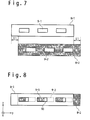
- FIGS. 7 and 8 are side views showing the rolling reduction apparatus according to a third embodiment of the present invention.
- a mechanism for variably controlling an opening area is added to the holes 5, 5-1, 5-2 and 5-3 in the first or second embodiment.
- FIGS. 7 and 8 show one example of the structure that allows the above control.
- a first plate member 8-1 and a second plate member 8-2 which are a pair of plates having the same shape are prepared.
- FIG. 7 shows the first plate member 8-1 and the second plate member 8-2, before the rolling reduction apparatus is assembled.
- a plurality of holes 9-1 are formed in the first plate member 8-1 to be arranged in the longitudinal direction.
- a plurality of holes 9-2 are formed in the second plate member 8-2 to be arranged in the longitudinal direction.
- a pitch between the holes 9-1 and a pitch between the holes 9-2 are equal.
- the first plate member 8-1 and the second plate member 8-2 are attached such that their planar shapes overlap with each other.
- Each of the first plate member 8-1 and the second plate member 8-2 can be slid in the longitudinal direction.
- a relative displacement L1 in the longitudinal direction between the first plate material 8-1 and the second plate material 8-2 can be controlled by a controller section (that is not shown).
- a driving mechanism such as an actuator can be used to control the displacement L1 to be a setting value and fix it to the value.
- a hole 10 is formed at a portion at which the hole 9-1 and the hole 9-2 overlap. This hole 10 corresponds to the hole 4 in the first and second embodiments. By controlling the displacement L1, it is possible to change the size of the hole 10.
- the rolling reduction apparatus is attached to both of the ends in the width direction on the bottom in the floating structure main body 1, for example, as the plate 4 shown in FIGS. 1 and 2 .
- one of the pair of plate members for example, the second plate member 8-2 is fixed to the floating structure main body 1.
- a worker controls the displacement L1 by remotely sliding the first plate member 8-1 along the second plate member 8-2 on the basis of the situation of the wave from a control room on the floating structure main body 1.
- the hole 10 can be adjusted to the size suitable for the rolling motion reduction, on the basis of data such as a rolling motion period of the floating structure.
- FIG. 9 shows another example to control the size of the hole.
- a first plate member 11-1 and a second plate member 11-2 are prepared in which a plurality of through-holes arranged in the longitudinal direction are formed.
- the first plate member 11-1 and the second plate member 11-2 are attached such that they overlap with each other and one of them can slide in a vertical direction when they are attached.
- a relative displacement L2 in the vertical direction can be controlled to adjust the size of a hole 12.
- the present invention has been described with reference to the embodiments. However, the present invention is not limited to the above-mentioned embodiments. Various modifications can be performed on the above-mentioned embodiments. The above-mentioned embodiments can be combined with each other.
Abstract
A rolling reduction apparatus includes a pair of plate members attached to both ends in a width direction on a bottom of a floating structure. Each of the plate members has a plurality of through-holes arranged in a longitudinal direction of the floating structure. The rolling motion of the floating structure is reduced because eddies are formed to consume energy when water passes through the through-holes.
Description
- The present invention relates to an apparatus for reducing a rolling motion of a floating structure.
- A technique for mooring a floating structure on water and using the floating structure for various use applications is put to practical use or researched. For example, in a plant referred to as FLNG (Floating LNG) or FPSO (Floating Production Storage & Offloading unit), a floating structure is floated offshore, and natural gas collected from an undersea gas field is liquidized to produce and accumulate LNG (Liquified Natural Gas). The accumulated LNG is transferred to a seaport by an LNG ship.
- For example, the floating structure is swung by waves generated on the water surface on the ocean. The swing motion of the floating structure is not desirable for the work on the floating structure. For example, in a case of the FLNG, a technique for suppressing the swing operation of the floating structure is required in order to improve an operation rate.
- A technique is known in which a perpendicular plate is provided on the side above the wave in the main body of the floating structure to penetrate through the water surface, so that the swing motion of the floating structure is reduced. Patent Literature 1 (
JP 2004-16105A - [Patent Literature 1]
JP 2004-161051A - A technique which can reduce a swing motion of a floating structure is demanded. A technique is demanded which reduces a swing motion effectively according to the situation of the swing motion of the floating structure.
- In a view of the present invention, a rolling suppression apparatus is provided with a pair of plate members attached to both of ends in a width direction on a bottom of a floating structure. Each of the plate members includes a plurality of through-holes arranged in a longitudinal direction of the plate member.
- Preferably, an upper end of each of the plate members in the motion suppression apparatus is attached to the bottom of the floating structure.
- Preferably, the plate members of the motion suppression system are attached to the floating structure by a support member to have a gap from the floating structure.
- Preferably, the rolling reduction apparatus is further provided with a control unit which controls the opening area of each of a plurality of through-holes.
- Preferably, each of the plate members is provided with a first plate and a second plate which is fixed on the floating structure. The first plate and the second plate are overlapped such that a first hole formed in the first plate and a second hole formed in the second plate to overlap with each other. The control unit slides the first plate along the second plate.
- In another view of the present invention, a floating structure is provided with the above rolling reduction apparatus.
- According to the present invention, the technique is provided which can reduce a rolling motion of the floating structure. Moreover, the technique is provided which can effectively reduce the rolling motion according to the situation of the rolling motion of the floating structure.
- The above-mentioned objects, other objects, effects and features of the present invention would be clarified from the descriptions of the embodiments in conjunction with the following drawings:
-
FIG. 1 is a perspective view of a floating structure; -
FIG. 2 is a front view of the floating structure; -
FIG. 3 is a front view of another floating structure; -
FIG. 4 is a front view of another floating structure; -
FIG. 5 is a front view of another floating structure; -
FIG. 6 is a side view of another floating structure. -
FIG. 7 shows a member configuring a rolling reduction apparatus; -
FIG. 8 shows the rolling reduction apparatus;
and -
FIG. 9 shows another rolling reduction apparatus. - Hereinafter, embodiments of the present invention will be described in detail with reference to the attached drawings.
FIGS. 1 and 2 show a floating structure according to a first embodiment of the present invention.FIG. 1 is a perspective view of the floating structure, andFIG. 2 is a front view when the floating structure is viewed from a bow side. A floating structuremain body 1 has a box shape in which a longitudinal direction is a direction of a ship length from abow 3 to astern 2, in a typical example. InFIG. 1 , the longitudinal direction is drawn as a Y-axis. In the floating structure, a swing motion in a roll direction which is a turn motion around the Y-axis is required to be reduced. - A rolling reduction apparatus is attached to both ends of the floating structure
main body 1 in a width direction, namely, an X-axis direction orthogonal to the longitudinal direction within a horizontal plane. The rolling reduction apparatus contains a pair of slender plate-shaped members. The longitudinal direction of each ofplates 4 is parallel to a front - rear direction (in many cases, the longitudinal direction) of the floating structuremain body 1. The long side of theplate 4 is attached to a bottom of the floating structuremain body 1. Theplate 4 is attached to protrude from the bottom of the floating structuremain body 1 into a vertically downward direction. Many holes (through-holes) 5 are formed to be arranged in the longitudinal direction of theplate 4. A Z-axis is orthogonal to the X-axis and the Y-axis. - Such a floating structure is floated and used on water. The floating structure swings by the influence of waves inputted to the floating structure
main body 1. As one of main swing motions, there is a case of generation of rolling. In such a case, theplate 4 is cyclically moved in a rolling direction against the water. In association with the motion, the water passes through theholes 5 of theplate 4 attached to the bottom of the floating structure. Eddy is generated on the downstream side of the water flow passing through theholes 5, and the energy of wave is attenuated. As a result, the rolling motion of the floating structure is suppressed. The rolling motion of the floating structure can be suppressed more effectively when the size of thehole 5 is determined on the basis of the situation of the rolling motion such as a period of the rolling motion of the floating structure. -
FIG. 3 is a front view showing a first modification example of the first embodiment. In the first modification example, a plate 4-1 in which holes 5-1 are formed is used, similarly toFIGS. 1 and 2 . However, the orientation of the plate 4-1 is different. In an example ofFIG. 3 , the plates 4-1 are attached to both of the ends in the width direction on the bottom of the floating structuremain body 1 so that the main surfaces of the plates 4-1 are horizontal. Even such a structure can suppress the rolling motion. There is an effect even if the plate is attached to the bottom in an oblique direction between angles inFIG. 1 or 2 andFIG. 3 . -
FIG. 4 is a front view showing a second modification example of the first embodiment. In the second modification example, a plate 4-2 contains two slender plate-shaped members of a first part 4-2-1 and a second part 4-2-2. The first part 4-2-1 protrudes vertically downwardly from the bottom of the floating structuremain body 1. The second part 4-2-2 protrudes outwardly from the lower end of the first part 4-2-1, with respect to the floating structuremain body 1 to have a main surface of a horizontal plane. Holes 5-2 are formed to be arranged in the longitudinal direction in each of the first part 4-2-1 and the second part 4-2-2. -
FIG. 5 is a front view showing a third modification example of the first embodiment. In the third modification example, a plate 4-3 is configured by two slender plate-shaped members of a first part 4-3-1 and a second part 4-3-2. The first part 4-3-1 protrudes outwardly from the bottom of the floating structuremain body 1 to have a main surface of a horizontal plane. The second part 4-3-2 protrudes vertically downwardly from the outer end of the first part 4-3-1. Holes 5-3 are formed to be arranged in the longitudinal direction in each of the first part 4-3-1 and the second part 4-3-2. - In even those modification examples, the rolling motion of the floating structure
main body 1 can be suppressed. -
FIG. 6 shows a floating structure according to a second embodiment of the present invention. In the first embodiment, the long side of theplate 4 is entirely adhered on the bottom surface of the floating structuremain body 1 without any gap. In the second embodiment, agap 6 is formed between the long side 4a of theplate 4 and a bottom surface 1a of the floating structuremain body 1. Theplate 4 is attached to the floating structuremain body 1 through asupport member 7. In such a structure, the water passes through not only theholes 5 but also thegap 6. Eddy is generated on the downstream side of the water passing through thegap 6. Thus, the energy of wave is attenuated, thereby suppressing the rolling motion of the floating structure. - Even in the second embodiment, the modification examples similar to
FIGS. 3 to 5 can be employed with regard to the shape of theplate 4. - The sizes of the hole and gap when the energy of wave is efficiently attenuated are different on the basis of the wavelength of an input wave. The sizes of the hole and gap are selected appropriately to the first or second embodiment. The second embodiment is advantageous because not only the
holes 5 but also thegap 6 can be used to reduce the rolling motion. In the first embodiment, it is easy to accomplish high strength only by using few members because theplate 4 can be directly attached to the bottom surface of the floating structuremain body 1. In particular, since the force of the wave is greatly applied to theplate 4, the high strength is required. -
FIGS. 7 and 8 are side views showing the rolling reduction apparatus according to a third embodiment of the present invention. In the third embodiment, a mechanism for variably controlling an opening area is added to theholes 5, 5-1, 5-2 and 5-3 in the first or second embodiment.FIGS. 7 and 8 show one example of the structure that allows the above control. A first plate member 8-1 and a second plate member 8-2 which are a pair of plates having the same shape are prepared.FIG. 7 shows the first plate member 8-1 and the second plate member 8-2, before the rolling reduction apparatus is assembled. A plurality of holes 9-1 are formed in the first plate member 8-1 to be arranged in the longitudinal direction. A plurality of holes 9-2 are formed in the second plate member 8-2 to be arranged in the longitudinal direction. A pitch between the holes 9-1 and a pitch between the holes 9-2 are equal. - The first plate member 8-1 and the second plate member 8-2 are attached such that their planar shapes overlap with each other. Each of the first plate member 8-1 and the second plate member 8-2 can be slid in the longitudinal direction. A relative displacement L1 in the longitudinal direction between the first plate material 8-1 and the second plate material 8-2 can be controlled by a controller section (that is not shown). For example, in the controller section, a driving mechanism such as an actuator can be used to control the displacement L1 to be a setting value and fix it to the value. In the situation in which the first plate member 8-1 and the second plate member 8-2 overlap, a
hole 10 is formed at a portion at which the hole 9-1 and the hole 9-2 overlap. Thishole 10 corresponds to thehole 4 in the first and second embodiments. By controlling the displacement L1, it is possible to change the size of thehole 10. - The rolling reduction apparatus is attached to both of the ends in the width direction on the bottom in the floating structure
main body 1, for example, as theplate 4 shown inFIGS. 1 and 2 . At this time, one of the pair of plate members, for example, the second plate member 8-2 is fixed to the floating structuremain body 1. A worker controls the displacement L1 by remotely sliding the first plate member 8-1 along the second plate member 8-2 on the basis of the situation of the wave from a control room on the floating structuremain body 1. By such a configuration, thehole 10 can be adjusted to the size suitable for the rolling motion reduction, on the basis of data such as a rolling motion period of the floating structure. -
FIG. 9 shows another example to control the size of the hole. Similarly toFIGS. 7 and 8 , a first plate member 11-1 and a second plate member 11-2 are prepared in which a plurality of through-holes arranged in the longitudinal direction are formed. The first plate member 11-1 and the second plate member 11-2 are attached such that they overlap with each other and one of them can slide in a vertical direction when they are attached. A relative displacement L2 in the vertical direction can be controlled to adjust the size of ahole 12. - As mentioned above, the present invention has been described with reference to the embodiments. However, the present invention is not limited to the above-mentioned embodiments. Various modifications can be performed on the above-mentioned embodiments. The above-mentioned embodiments can be combined with each other.
- This application claims a priority based on Japanese Patent Application No.
JP 2010-244092 filed on October 29, 2010
Claims (6)
- A rolling reduction apparatus comprising:a pair of plate members attached to both ends in a width direction on a bottom of a floating structure,
wherein each of said plate members comprises a plurality of through-holes arranged in a longitudinal direction of said floating structure. - The rolling reduction apparatus according to claim 1, wherein an upper end of each of the pair of plate members is firmly attached to the bottom of said floating structure.
- The rolling reduction apparatus according to claim 1, wherein the pair of plate members is attached to said floating structure by a support member to form a space between each of said plate members and said floating structure.
- The rolling reduction apparatus according to any of claims 1 to 3, further comprising:a control unit which controls an opening area of said plurality of through-holes.
- The rolling reduction apparatus according to claim 4, wherein each of said plate members comprises:a first plate; anda second plate fixed on said floating structure,
wherein said first plate and said second plate overlaps with each other such that a first through-hole of through-holes formed in said first plate and a second through-hole of through holes formed in said second plate overlap with each other, and
wherein said control unit slides said first plate along said second plate. - A floating structure comprising the rolling reduction apparatus according to any of claims 1 to 5.
Applications Claiming Priority (2)
| Application Number | Priority Date | Filing Date | Title |
|---|---|---|---|
| JP2010244092A JP2012096601A (en) | 2010-10-29 | 2010-10-29 | Oscillation reducing device for floating body |
| PCT/JP2011/074508 WO2012057112A1 (en) | 2010-10-29 | 2011-10-25 | Rocking-reduction device for floating body |
Publications (1)
| Publication Number | Publication Date |
|---|---|
| EP2634081A1 true EP2634081A1 (en) | 2013-09-04 |
Family
ID=45993819
Family Applications (1)
| Application Number | Title | Priority Date | Filing Date |
|---|---|---|---|
| EP11836245.8A Withdrawn EP2634081A1 (en) | 2010-10-29 | 2011-10-25 | Rocking-reduction device for floating body |
Country Status (8)
| Country | Link |
|---|---|
| US (1) | US20130098281A1 (en) |
| EP (1) | EP2634081A1 (en) |
| JP (1) | JP2012096601A (en) |
| KR (1) | KR20130029096A (en) |
| CN (1) | CN102971210A (en) |
| BR (1) | BR112012033454A2 (en) |
| RU (1) | RU2012157074A (en) |
| WO (1) | WO2012057112A1 (en) |
Families Citing this family (9)
| Publication number | Priority date | Publication date | Assignee | Title |
|---|---|---|---|---|
| US9238501B1 (en) * | 2013-12-17 | 2016-01-19 | The United States Of America As Represented By The Secretary Of The Navy | Bilge keel with porous leading edge |
| JP6196687B2 (en) * | 2013-12-27 | 2017-09-13 | 三菱重工業株式会社 | Shake reduction device and floating body provided with the same |
| KR101690999B1 (en) * | 2014-11-11 | 2016-12-29 | 삼성중공업 주식회사 | Apparatus for reducing the rolling motion |
| JP6415314B2 (en) * | 2014-12-26 | 2018-10-31 | 三菱重工業株式会社 | Shake reduction device and floating body provided with the same |
| JP6527346B2 (en) * | 2015-02-13 | 2019-06-05 | 三菱重工業株式会社 | Motion reduction device and floating body provided with the same |
| CN105109615B (en) * | 2015-08-31 | 2017-10-27 | 许庆松 | Overturn-preventing catamaran |
| FR3088893A1 (en) * | 2018-11-23 | 2020-05-29 | Safier Ingenierie | Floating structure skirt |
| CN111391981A (en) * | 2020-03-18 | 2020-07-10 | 刘江平 | Floating cushion |
| CN112224361A (en) * | 2020-10-22 | 2021-01-15 | 中国人民解放军海军航空大学 | Offshore lifesaving floating stretcher |
Family Cites Families (18)
| Publication number | Priority date | Publication date | Assignee | Title |
|---|---|---|---|---|
| US3915108A (en) * | 1973-09-24 | 1975-10-28 | Global Marine Inc | Apparatus for controlling heave pitch and roll of a floating vessel |
| DE3217185A1 (en) * | 1981-10-29 | 1983-11-10 | Georg 4320 Hattingen Keiderling | Skimming or buoyancy plates adjustable in length and width |
| JPS5881888A (en) * | 1981-11-12 | 1983-05-17 | Sanoyasu:Kk | Rock damping pontoon |
| JPS6172117A (en) * | 1984-09-18 | 1986-04-14 | Mitsui Eng & Shipbuild Co Ltd | Floating breakwater |
| JPH03204391A (en) * | 1989-12-29 | 1991-09-05 | Taiyo Gijutsu Kaihatsu Kk | Pontoon |
| JPH0471988A (en) * | 1990-07-11 | 1992-03-06 | Taiyo Gijutsu Kaihatsu Kk | Pontoon |
| JP2564424Y2 (en) * | 1992-07-30 | 1998-03-09 | 三菱重工業株式会社 | Well opening rapid adjustable floating offshore structure |
| NO300884B1 (en) * | 1995-12-06 | 1997-08-11 | Fred Olsen | Wave dampers for floating structures |
| JP2000135999A (en) * | 1998-10-30 | 2000-05-16 | Mitsubishi Heavy Ind Ltd | Wave resistance large floating body |
| JP4358456B2 (en) * | 2000-05-16 | 2009-11-04 | 三菱重工業株式会社 | Floating body fluctuation reducing device and floating body provided with the same |
| JP2003034289A (en) * | 2001-07-19 | 2003-02-04 | Mitsubishi Heavy Ind Ltd | Floating body reduced in rolling |
| JP2004016105A (en) | 2002-06-17 | 2004-01-22 | Toa:Kk | Method for processing polished rice |
| JP2004058691A (en) * | 2002-07-24 | 2004-02-26 | Mitsubishi Heavy Ind Ltd | Device for reducing rocking of floating body and floating body provided with the same |
| JP4220759B2 (en) | 2002-11-11 | 2009-02-04 | 三菱重工業株式会社 | Floating body fluctuation reducing device and floating body provided with the same |
| FR2857347B1 (en) * | 2003-07-10 | 2005-09-16 | Doris Engineering | FLOATING TERMINAL FOR LOADING / UNLOADING SHIPS SUCH AS METHANIERS |
| KR100885990B1 (en) * | 2006-05-11 | 2009-03-03 | 삼성중공업 주식회사 | Anti-sloshing device in Moon-pool |
| KR101164085B1 (en) * | 2009-09-15 | 2012-07-12 | 대우조선해양 주식회사 | Roll Suppression Device for offshore structure |
| JP5638380B2 (en) * | 2010-12-20 | 2014-12-10 | 三菱重工業株式会社 | Shake reduction device and shake reduction floating body |
-
2010
- 2010-10-29 JP JP2010244092A patent/JP2012096601A/en not_active Withdrawn
-
2011
- 2011-10-25 CN CN2011800322495A patent/CN102971210A/en active Pending
- 2011-10-25 EP EP11836245.8A patent/EP2634081A1/en not_active Withdrawn
- 2011-10-25 WO PCT/JP2011/074508 patent/WO2012057112A1/en active Application Filing
- 2011-10-25 KR KR1020127034022A patent/KR20130029096A/en not_active Application Discontinuation
- 2011-10-25 RU RU2012157074/11A patent/RU2012157074A/en not_active Application Discontinuation
- 2011-10-25 BR BR112012033454A patent/BR112012033454A2/en not_active IP Right Cessation
- 2011-10-25 US US13/807,083 patent/US20130098281A1/en not_active Abandoned
Non-Patent Citations (1)
| Title |
|---|
| See references of WO2012057112A1 * |
Also Published As
| Publication number | Publication date |
|---|---|
| KR20130029096A (en) | 2013-03-21 |
| JP2012096601A (en) | 2012-05-24 |
| RU2012157074A (en) | 2014-06-27 |
| WO2012057112A1 (en) | 2012-05-03 |
| CN102971210A (en) | 2013-03-13 |
| BR112012033454A2 (en) | 2016-11-22 |
| US20130098281A1 (en) | 2013-04-25 |
Similar Documents
| Publication | Publication Date | Title |
|---|---|---|
| EP2634081A1 (en) | Rocking-reduction device for floating body | |
| Stappenbelt | Splitter-plate wake stabilisation and low aspect ratio cylinder flow-induced vibration mitigation | |
| EP2391533B1 (en) | A ship's fore body form | |
| US8347803B2 (en) | Roll suppression device for offshore structure | |
| CA2891245A1 (en) | Systems and methods for dynamic positioning | |
| EP2162347A1 (en) | Enhancement of vortex induced forces and motion through surface roughness control | |
| Wang et al. | Reliability-based robust dynamic positioning for a turret-moored floating production storage and offloading vessel with unknown time-varying disturbances and input saturation | |
| JP2007239942A (en) | Active vibration control method and device | |
| Eydi et al. | Comparative analysis of the flow control over a circular cylinder with detached flexible and rigid splitter plates | |
| WO2011077053A3 (en) | Pendular system for transporting a civil engineering structure in an aquatic medium | |
| van Albada et al. | A novel approach to anti-sway control for marine shipboard cranes. | |
| CN104736839B (en) | System for generating energy by the effect of wave | |
| Bjørnø et al. | Modeling, parameter identification and thruster-assisted position mooring of c/s inocean cat i drillship | |
| Zhao et al. | Applying strip theory based linear seakeeping loads to 3D full ship finite element models | |
| Van Kessel et al. | Wave-induced structural loads on different types of aircushion supported structures | |
| JP2015169173A (en) | floating structure | |
| Ferreira et al. | Asymmetric FPSO roll response due to the influence of lines arrangement | |
| JP5965142B2 (en) | Azimuth control device, floating body, and shaking reduction method | |
| Liang et al. | Improving the vertical motion of wave piercing catamaran using T-foil | |
| Freire et al. | Defining a parameter of effectiveness for the suppression of vortex-induced vibration | |
| KR20130018001A (en) | Apparatus for decreasing ship rolling | |
| Gambarine et al. | Experimental study about the influence of the free end effects on vortex-induced vibration of floating cylinder with low aspect of ratio | |
| JP5113283B2 (en) | Columnar structure installation system and columnar structure installation method | |
| Wang et al. | Novel controller for the coupled surge-pitch problem by controlling the metacentric height of sandglass-type FDPSO | |
| Jordan et al. | Oscillation control in teleoperated underwater vehicles subject to cable perturbations |
Legal Events
| Date | Code | Title | Description |
|---|---|---|---|
| PUAI | Public reference made under article 153(3) epc to a published international application that has entered the european phase |
Free format text: ORIGINAL CODE: 0009012 |
|
| 17P | Request for examination filed |
Effective date: 20121228 |
|
| AK | Designated contracting states |
Kind code of ref document: A1 Designated state(s): AL AT BE BG CH CY CZ DE DK EE ES FI FR GB GR HR HU IE IS IT LI LT LU LV MC MK MT NL NO PL PT RO RS SE SI SK SM TR |
|
| DAX | Request for extension of the european patent (deleted) | ||
| STAA | Information on the status of an ep patent application or granted ep patent |
Free format text: STATUS: THE APPLICATION HAS BEEN WITHDRAWN |
|
| 18W | Application withdrawn |
Effective date: 20140221 |