EP2634000A1 - Optical scanning device and image forming apparatus using same - Google Patents
Optical scanning device and image forming apparatus using same Download PDFInfo
- Publication number
- EP2634000A1 EP2634000A1 EP13000947.5A EP13000947A EP2634000A1 EP 2634000 A1 EP2634000 A1 EP 2634000A1 EP 13000947 A EP13000947 A EP 13000947A EP 2634000 A1 EP2634000 A1 EP 2634000A1
- Authority
- EP
- European Patent Office
- Prior art keywords
- face
- axis
- scanning direction
- lens
- curvature
- Prior art date
- Legal status (The legal status is an assumption and is not a legal conclusion. Google has not performed a legal analysis and makes no representation as to the accuracy of the status listed.)
- Granted
Links
- 230000003287 optical effect Effects 0.000 title claims abstract description 75
- 230000007423 decrease Effects 0.000 claims abstract description 7
- 238000003384 imaging method Methods 0.000 claims description 30
- 230000002093 peripheral effect Effects 0.000 claims description 28
- 108091008695 photoreceptors Proteins 0.000 description 26
- 238000010586 diagram Methods 0.000 description 16
- 238000012546 transfer Methods 0.000 description 11
- 239000004065 semiconductor Substances 0.000 description 10
- 238000000034 method Methods 0.000 description 5
- 239000000758 substrate Substances 0.000 description 5
- 238000005516 engineering process Methods 0.000 description 4
- 238000003754 machining Methods 0.000 description 3
- 239000000463 material Substances 0.000 description 3
- 238000004140 cleaning Methods 0.000 description 2
- 238000006073 displacement reaction Methods 0.000 description 2
- 230000002349 favourable effect Effects 0.000 description 2
- 239000002184 metal Substances 0.000 description 2
- 229910052751 metal Inorganic materials 0.000 description 2
- 238000012986 modification Methods 0.000 description 2
- 230000004048 modification Effects 0.000 description 2
- 238000000465 moulding Methods 0.000 description 2
- 238000012545 processing Methods 0.000 description 2
- 239000011347 resin Substances 0.000 description 2
- 229920005989 resin Polymers 0.000 description 2
- 238000010276 construction Methods 0.000 description 1
- 238000012937 correction Methods 0.000 description 1
- 238000007599 discharging Methods 0.000 description 1
- 230000000694 effects Effects 0.000 description 1
- 238000010438 heat treatment Methods 0.000 description 1
- 230000001678 irradiating effect Effects 0.000 description 1
- 230000005499 meniscus Effects 0.000 description 1
- 238000000926 separation method Methods 0.000 description 1
- 238000004904 shortening Methods 0.000 description 1
- 238000011144 upstream manufacturing Methods 0.000 description 1
Images






Classifications
-
- G—PHYSICS
- G02—OPTICS
- G02B—OPTICAL ELEMENTS, SYSTEMS OR APPARATUS
- G02B26/00—Optical devices or arrangements for the control of light using movable or deformable optical elements
- G02B26/08—Optical devices or arrangements for the control of light using movable or deformable optical elements for controlling the direction of light
- G02B26/10—Scanning systems
-
- B—PERFORMING OPERATIONS; TRANSPORTING
- B41—PRINTING; LINING MACHINES; TYPEWRITERS; STAMPS
- B41J—TYPEWRITERS; SELECTIVE PRINTING MECHANISMS, i.e. MECHANISMS PRINTING OTHERWISE THAN FROM A FORME; CORRECTION OF TYPOGRAPHICAL ERRORS
- B41J2/00—Typewriters or selective printing mechanisms characterised by the printing or marking process for which they are designed
- B41J2/435—Typewriters or selective printing mechanisms characterised by the printing or marking process for which they are designed characterised by selective application of radiation to a printing material or impression-transfer material
- B41J2/47—Typewriters or selective printing mechanisms characterised by the printing or marking process for which they are designed characterised by selective application of radiation to a printing material or impression-transfer material using the combination of scanning and modulation of light
- B41J2/471—Typewriters or selective printing mechanisms characterised by the printing or marking process for which they are designed characterised by selective application of radiation to a printing material or impression-transfer material using the combination of scanning and modulation of light using dot sequential main scanning by means of a light deflector, e.g. a rotating polygonal mirror
- B41J2/473—Typewriters or selective printing mechanisms characterised by the printing or marking process for which they are designed characterised by selective application of radiation to a printing material or impression-transfer material using the combination of scanning and modulation of light using dot sequential main scanning by means of a light deflector, e.g. a rotating polygonal mirror using multiple light beams, wavelengths or colours
-
- G—PHYSICS
- G02—OPTICS
- G02B—OPTICAL ELEMENTS, SYSTEMS OR APPARATUS
- G02B13/00—Optical objectives specially designed for the purposes specified below
- G02B13/0005—Optical objectives specially designed for the purposes specified below having F-Theta characteristic
-
- G—PHYSICS
- G02—OPTICS
- G02B—OPTICAL ELEMENTS, SYSTEMS OR APPARATUS
- G02B26/00—Optical devices or arrangements for the control of light using movable or deformable optical elements
- G02B26/08—Optical devices or arrangements for the control of light using movable or deformable optical elements for controlling the direction of light
- G02B26/10—Scanning systems
- G02B26/12—Scanning systems using multifaceted mirrors
- G02B26/125—Details of the optical system between the polygonal mirror and the image plane
-
- G—PHYSICS
- G03—PHOTOGRAPHY; CINEMATOGRAPHY; ANALOGOUS TECHNIQUES USING WAVES OTHER THAN OPTICAL WAVES; ELECTROGRAPHY; HOLOGRAPHY
- G03G—ELECTROGRAPHY; ELECTROPHOTOGRAPHY; MAGNETOGRAPHY
- G03G15/00—Apparatus for electrographic processes using a charge pattern
- G03G15/04—Apparatus for electrographic processes using a charge pattern for exposing, i.e. imagewise exposure by optically projecting the original image on a photoconductive recording material
- G03G15/04036—Details of illuminating systems, e.g. lamps, reflectors
-
- G—PHYSICS
- G02—OPTICS
- G02B—OPTICAL ELEMENTS, SYSTEMS OR APPARATUS
- G02B26/00—Optical devices or arrangements for the control of light using movable or deformable optical elements
- G02B26/08—Optical devices or arrangements for the control of light using movable or deformable optical elements for controlling the direction of light
- G02B26/10—Scanning systems
- G02B26/101—Scanning systems with both horizontal and vertical deflecting means, e.g. raster or XY scanners
Definitions
- the image forming unit 100 performs processing of forming a toner image on a sheet, and includes a charging device 102, a photoreceptor drum 103 (image carrier), a developing device 105, a transfer roller 106, a cleaning device 107, and a fixing unit 108.
- the polygon mirror 26 is a polygonal mirror in which a deflective surface 26R is formed along each side of a regular hexagon.
- a rotating axis 27S of the polygon motor 27 is connected to the center position of the polygon mirror 26.
- the polygon mirror 26 rotates around the rotating axis 27S as a result of the polygon motor 27 being rotatively driven, and deflects and scans the laser beam B which is emitted from the semiconductor laser 22 and imaged via the collimator lens 23 and the cylindrical lens 24.
- the imaging optical system of the Example is configured, as shown in Fig. 3 , in order from the semiconductor laser 22 side, from one collimator lens 23, one cylindrical lens 24, and one f ⁇ lens 28. Moreover, the optical performance of the respective lenses of the Example and the face shape of the f ⁇ lens 28 are as per Table 1.
- R s R s 0 + B 1 ⁇ y + B 2 ⁇ y 2 + B 3 ⁇ y 3 + B 4 ⁇ y 4 + B 5 ⁇ y 5 + B 6 ⁇ y 6 + B ⁇ 8 ⁇ y 8 + B ⁇ 10 ⁇ y 10
- Z s C s ⁇ x 2 1 - ⁇ 1 - 1 + K x C s 2 ⁇ x 2
- the variation in the focal distance of the f ⁇ lens 28 in the sub scanning direction relative to the image height will increase, and the spot diameter of the light beam will change depending on the image height.
- changes in the spot diameter can be inhibited.
- a positional variation of the deflective surface 26R of the polygon mirror 26 in the optical axis direction will arise during the deflection/scanning process, and this will affect the imaging performance.
Landscapes
- Physics & Mathematics (AREA)
- General Physics & Mathematics (AREA)
- Optics & Photonics (AREA)
- Mechanical Optical Scanning Systems (AREA)
- Facsimile Scanning Arrangements (AREA)
- Lenses (AREA)
- Laser Beam Printer (AREA)
- Exposure Or Original Feeding In Electrophotography (AREA)
Abstract
Description
- This application relates to and claims priority from Japanese Patent Application No.
2012-40221, filed on February 27, 2012 - The present disclosure relates to an optical scanning device including a scanning lens which performs, on a surface to be scanned, imaging of a light beam that was deflected and scanned, and an image forming apparatus using the foregoing optical scanning device.
- For example, a general optical scanning device that is used, for example, in laser printers and copiers includes a light source which emits a laser beam, a polygon mirror which reflects and deflects/scans the laser beam, and a scanning lens which performs imaging of the laser beam deflected for scanning on a peripheral surface (surface to be scanned) of a photoreceptor drum. As the scanning lens, a lens having a distortion (fθ characteristics) in which the angle of the incident light and the height of the image become a proportional relation is used. Moreover, the foregoing scanning lens is generally manufactured by molding a resin material in a metal mold.
- One of the optical properties that are demanded in this kind of optical scanning device is that the field curvature is favorably corrected and the spot diameter of the beam generated by the laser beam is aligned across the entire image height. As conventional technology, known is technology which inhibits changes in the spot diameter by causing the curvature of the scanning lens in the sub scanning direction to continuously change from on axis toward off axis, and inverting the symbol of the curvature from on axis toward off axis. For example, a lens that has a meniscus shape on axis and a shape in which both surfaces are convex off axis is used as the scanning lens.
- Nevertheless, the scanning lens of the foregoing conventional technology has a problem in that it is difficult to produce. In other words, upon processing the mold of the foregoing scanning lens, it is necessary to create a shape that will invert the symbol of the curvature in the sub scanning direction from on axis toward off axis. With this kind of inverted part of the curvature symbol, a discontinuous section tends to arise on the mold surface. Accordingly, a great difficulty is encountered in the die machining.
- An object of the present disclosure is to provide an optical scanning device including a scanning lens in which the die machining thereof is easy and which yields superior optical performance, as well as an image forming apparatus using such an optical scanning device.
- The optical scanning device according to one aspect of the present disclosure includes a light source which emits a light beam, a deflector, an incident optical system and one scanning lens. The deflector includes a deflective surface which reflects and then deflects/scans the light beam emitted from the light source. The incident optical system causes the light beam emitted from the light source to enter the deflector from an oblique direction. The scanning lens includes a first face facing the deflector and a second face on an opposite side to the first face, and performs imaging of the light beam deflected/scanned on a surface to be scanned. In a main scanning direction cross section of the scanning lens, when a scanning range is separated, with on axis as a reference, into an image height region of a first direction and an image height region of a second direction that is opposite to the first direction, the incident optical system is disposed on a side of the image height region of the first direction. Curvature of the first face in the sub scanning direction cross section decreases from on axis toward off axis in a main scanning direction, and curvature of the second face in the sub scanning direction cross section increases from off axis of the first direction toward the second direction in the main scanning direction.
- The image forming apparatus according to another aspect of the present disclosure includes an image carrier which carries an electrostatic latent image, and an optical scanning device which irradiates a light beam, with a peripheral surface of the image carrier being used as a surface to be scanned, wherein the optical scanning device includes the foregoing configuration.
-
-
Fig. 1 is a cross section showing the schematic configuration of the printer according to one embodiment of the present disclosure; -
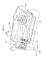
Fig. 2 is a perspective view showing the internal structure of the optical scanning device according to the embodiment; -
Fig. 3 is a light path diagram showing the configuration of the optical scanning device in the main scanning cross section; -
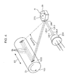
Fig. 4 is a schematic perspective view explaining the exposure status of the photoreceptor drum in the case of using a light source of the multibeam method; -
Fig. 5 is a graph showing the fluctuation of the focal distance of the scanning lens in the sub scanning direction relative to the image height in the case of not applying the present disclosure; -
Fig. 6A and Fig. 6B are diagrams explaining the distance between the principal point of the scanning lens in the sub scanning direction, and the deflective surface and the surface to be scanned; -
Fig. 7 is a graph showing the relation of the image height and the imaging position in the sub scanning direction; -
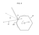
Fig. 8 is a diagram explaining the position variation factor of the deflective surface of the polygon mirror; -
Fig. 9A and Fig. 9B are schematic diagrams explaining the fluctuation of the imaging position due to the image height; -
Fig. 10A is a light path diagram of the sub scanning direction cross section on the axis, andFig. 10B is a light path diagram of the sub scanning direction cross section off the axis; -
Fig. 11 is a graph showing the curvature change of the first face and the second face of the scanning lens in the sub scanning direction; -
Fig. 12 is a graph showing the relation of the curvature change of the first face of the scanning lens in the sub scanning direction and the conditional equation; -
Fig. 13 is a graph showing the optical property of the optical scanning device having the optical system of the Example; and -
Fig. 14 is a graph showing the optical property of the optical scanning device having the optical system of the Example. - The optical scanning device according to one embodiment of the present disclosure is now explained with reference to the appended drawings.
Fig. 1 is a cross section showing the schematic configuration of a printer 1 (example of an image forming apparatus) according to one embodiment of the present disclosure. Note that the image forming apparatus is not limited to theprinter 1, and may also be a copier, a facsimile, a multi-function machine or the like. Theprinter 1 includes a box-shaped housing 101, and animage forming unit 100, anoptical scanning device 104, andpaper feeding cassettes housing 101. Thepaper feeding cassettes printer 1. - The
image forming unit 100 performs processing of forming a toner image on a sheet, and includes acharging device 102, a photoreceptor drum 103 (image carrier), a developingdevice 105, atransfer roller 106, acleaning device 107, and afixing unit 108. - The
photoreceptor drum 103 is a cylindrical member, and an electrostatic latent image and a toner image are formed on a peripheral face thereof. Thephotoreceptor drum 103 receives drive force from a motor not shown, and is rotated in a clockwise direction shown with an arrow A inFig. 1 . Thecharging device 102 substantially uniformly charges the surface of thephotoreceptor drum 103. - The developing
device 105 supplies a toner to the peripheral surface of thephotoreceptor drum 103, on which an electrostatic latent image was formed, and thereby forms a toner image. The developingdevice 105 includes a developing roller for carrying the toner, and a screw for agitating and delivering the toner. The toner image formed on thephotoreceptor drum 103 is transferred to a sheet that is fed from thepaper feeding cassettes feeding path 300. The toner is supplied to the developingdevice 105 from a toner container not shown. - The
transfer roller 106 is disposed facing a lateral side of thephotoreceptor drum 103, and a transfer nip portion is formed by thetransfer roller 106 and thephotoreceptor drum 103. Thetransfer roller 106 is configured from a rubber material with conductivity and provided with a transfer bias, and transfers the toner image formed on thephotoreceptor drum 103 to the sheet. Thecleaning device 107 cleans the peripheral surface of thephotoreceptor drum 103 after the toner image is transferred. - The
fixing unit 108 includes a fixing roller with a heater build therein, and a pressure roller provided at a position facing the fixing roller. Thefixing unit 108 fixes the toner image, which was transferred to a sheet, on the sheet while conveying and heating the sheet with the toner image formed thereon with the rollers. - The
optical scanning device 104 forms an electrostatic latent image by irradiating a laser beam according to image data that is input from external equipment such as a personal computer to the peripheral surface (surface to be scanned) of thephotoreceptor drum 103 that was substantially uniformly charged by thecharging device 102. Theoptical scanning device 104 will be described in detail later. - The
paper feeding cassettes feeding path 300 for delivering the sheets is disposed between thepaper feeding cassettes image forming unit 100. Thefeeding path 300 is provided with paper feed roller pairs 213, 223, transport roller pairs 214, 224, and a resistroller pair 215. Moreover, disposed on the downstream side of the fixingunit 108 are atransport roller pair 109, and adischarge roller pair 110 for discharging the sheets to thepaper discharge tray 119. - The image forming operation of the
printer 1 is now briefly explained. Foremost, the peripheral surface of thephotoreceptor drum 103 is substantially uniformly charged with the chargingdevice 102. The charged peripheral surface of thephotoreceptor drum 103 is exposed by a laser beam emitted from thenoptical scanning device 104, and an electrostatic latent image of the image to be formed on the sheet P is formed on the peripheral surface of thephotoreceptor drum 103. The electrostatic latent image is developed as a toner image as a result of the toner being supplied from the developingdevice 105 to the peripheral surface of thephotoreceptor drum 103. Meanwhile, the sheet P is fed from thepaper feeding cassettes feeding path 300 by thepickup rollers roller pair 215, and delivered to the transfer nip portion between thetransfer roller 106 and thephotoreceptor drum 103 at a predetermined timing. The toner image is transferred to the sheet P as a result of the sheet P passing through the transfer nip portion. After the foregoing transfer operation, the sheet P is delivered to the fixingunit 108, and the toner image is fixed to the sheet P. Subsequently, the sheet P is discharged to thepaper discharge tray 119 by thetransport roller pair 109 and thedischarge roller pair 110. - The detailed structure of the
optical scanning device 104 according to this embodiment is now explained.Fig. 2 is a perspective view showing the internal structure of theoptical scanning device 104, andFig. 3 is a light path diagram showing the configuration of theoptical scanning device 104 in the main scanning cross section. Theoptical scanning device 104 includes ahousing 104H, and a laser unit 20 (light source), a collimator lens 23 (part of the incident optical system), a cylindrical lens 24 (part of the incident optical system), a polygon mirror 26 (deflector), and a fθ lens 28 (scanning lens) housed in thehousing 104H. In the indication of directions shown inFig. 2 , the left-right direction is the main scanning direction. Theoptical scanning device 104 of this embodiment is an optical scanning device in which the scanning lens is configured from only one lens (fθ lens 28). - The
housing 104H includes abottom plate 141 as a base member on which various members are mounted,side plates 142 that are erected substantially vertically from the peripheral edges of thebottom plate 141, and a cover for covering the upside of theside plates 142. Note that, inFig. 2 , since a state where the cover has been removed is shown, the cover is not indicated. Thehousing 104H has a substantially square shape when viewed from the top face. Theside plates 142 include afront side plate 142F which faces aperipheral surface 103S of thephotoreceptor drum 103 when theoptical scanning device 104 is mounted on theprinter 1, arear side plate 142B which faces thefront side plate 142F, and aright side plate 142R and aleft side plate 142L which connect both sides of thefront side plate 142F and therear side plate 142B. - The
bottom plate 141 is provided with arecess 143 at a location which is adjacent to therear side plate 142B and which has a height that is lower than its surroundings. Apolygon mirror 26 is disposed in therecess 143, and thelaser unit 20, thecollimator lens 23, thecylindrical lens 24 and thefθ lens 28 are disposed in a region other than therecess 143 of thebottom plate 141. Thefront side plate 142F is provided with awindow part 144 which is formed by notching thefront side plate 142F from the upper edge up to around the intermediate portion thereof. Even in a state where the cover (not shown) is mounted, thewindow part 144 remains an opening of thehousing 104H. Moreover, a first holdingmember 145 and asecond holding member 146 are provided on a top face of thebottom plate 141 near theleft side plate 142L. A minute gap is provided between theleft side plate 142L and the first holdingmember 145, and between theleft side plate 142L and the second holdingmember 146, respectively. - The
laser unit 20 includes asubstrate 21, and a substantially cylindrically shapedsemiconductor laser 22 mounted on one face of thesubstrate 21. Thesemiconductor laser 22 is a light source which emits a laser beam B (light beam) of a predetermined wavelength. Mounted on thesubstrate 21 are asemiconductor laser 22, and a drive circuit component for driving thesemiconductor laser 22. Thelaser unit 20 is mounted on the top face of thebottom plate 141 such that thesubstrate 21 is sandwiched in the gap formed between the first holdingmember 145 and theleft side plate 142L and the gap formed between the second holdingmember 146 and theleft side plate 142L respectively, and such that thesemiconductor laser 22 is fitted between the first holdingmember 145 and the second holdingmember 146. The irradiation position of the laser beam B can be adjusted by adjusting the position that thesubstrate 21 is fitted into the gap. - The
collimator lens 23 converts the laser beam B, which is emitted from thesemiconductor laser 22 and diffused, into parallel light or light that is close to parallel. Thecollimator lens 23 is mounted on aslide plate 25, and theslide plate 25 can move in the optical axis direction on thebottom plate 141. The mounting position of thecollimator lens 23 can be adjusted by moving theslide plate 25. - The
cylindrical lens 24 converts the parallel light into linear light that is long in a main scanning direction, and images the linear light on a reflecting surface of thepolygon mirror 26. - The
polygon mirror 26 is a polygonal mirror in which adeflective surface 26R is formed along each side of a regular hexagon. Arotating axis 27S of thepolygon motor 27 is connected to the center position of thepolygon mirror 26. Thepolygon mirror 26 rotates around the rotatingaxis 27S as a result of thepolygon motor 27 being rotatively driven, and deflects and scans the laser beam B which is emitted from thesemiconductor laser 22 and imaged via thecollimator lens 23 and thecylindrical lens 24. - The
collimator lens 23 and thecylindrical lens 24 are an incident optical system which causes the laser beam B to enter thepolygon mirror 26, and in this embodiment is configured from an oblique-incident optical system. Referring toFig. 3 , in the main scanning direction cross section, with an on-axis point BA where an on-axis light beam comes into contact with the surface to be scanned (peripheral surface 103S) as the reference regarding the scanning range, the regions are separated as follows; namely, a direction (first direction) that is upstream of the rotating direction (indicated with an arrow inFig. 3 ) of thepolygon mirror 26 is set as the minus-side image height region, and the downstream side direction (second direction) is set as the plus-side image height region. In the foregoing separation, the incident optical system is disposed on a side of the minus-side image height region. - The
fθ lens 28 is a lens having a distortion (fθ characteristics) in which the angle of the incident light and the image height are of a proportional relation, and is a lens that is elongated in the main scanning direction. Thefθ lens 28 is disposed between thewindow part 144 and thepolygon mirror 26. The laser beam B reflected off thepolygon mirror 26 is condensed by thefθ lens 28, and images on theperipheral face 103S of thephotoreceptor drum 103 through thewindow part 144 of thehousing 104H. Thefθ lens 28 is manufactured by molding a translucent resin material in a metal mold. Thefθ lens 28 includes an entrance face 281 (first face; hereinafter referred to as the "R1 face") which faces thepolygon mirror 26 and to which the laser beam B enters, and an exit face 282 (second face; hereinafter referred to as the "R2 face") which is a face on a side that is opposite to theentrance face 281 and from which the laser beam B exits. -
Fig. 4 is a schematic perspective view explaining the exposure status of thephotoreceptor drum 103 in the case of using the laser unit 20A of the multibeam method as the light source. Here, illustrated is a laser unit 20A which emits four laser beams LB-1 to LB-4. The laser unit 20A includes four semiconductor laser (not shown) arranged linearly at given intervals. - Pursuant to the rotation of the
photoreceptor drum 103 in an arrow D1 direction (sub scanning direction D1) and the rotation of thepolygon mirror 26 around the rotatingaxis 27S, the four laser beams LB-1 to LB-4 are reflected off thedeflective surface 26R of thepolygon mirror 26, theperipheral surface 103S (surface to be scanned) of thephotoreceptor drum 103 is scanned along the main scanning direction D2. Consequently, four scanning lines SL are drawn on theperipheral surface 103S. Since the laser beams LB-1 to LB-4 are modulated according to the image data, an electrostatic latent image according to the image data is formed on theperipheral surface 103S of thephotoreceptor drum 103. - Here, the four laser beams LB-1 to LB-4 draw the four scanning lines SL in the main scanning direction D2 in a state of being arranged in the order of laser beams LB-1, LB-2, LB-3, LB-4 in the sub scanning direction D1. This is because, as described above, the four semiconductor lasers are arranged linearly in given intervals. The beam pitch of these laser beams LB-1 to LB-4 in the sub scanning direction defines the resolution (dpi) of the drawn image. Accordingly, with the scanning optical system equipped in the
optical scanning device 104 it is important that the laser beams LB-1 to LB-4 are imaged on theperipheral surface 103S so that the beam pitch does not change due to the image height. - In the
optical scanning device 104 explained above, there are demands for shortening the gap between thepolygon mirror 26 and theperipheral surface 103S of thephotoreceptor drum 103 in order to downsize theoptical scanning device 104 itself. In the foregoing case, the focal distance of thefθ lens 28 needs to be shortened. When the same scanning width is scanned using thefθ lens 28 having a short focal distance, the oscillating angle α (refer toFig. 3 ) of the light beam based on thepolygon mirror 26 needs to be increased. In the foregoing case, the difference between the light path length of the on-axis light beam and the light path length of the off-axis light beam of thefθ lens 28 will increase. In other words, the light path length of the light beam deflected by thepolygon mirror 26 reaching the end part of the minus-side and plus-side image height regions will be considerably longer than the light path length of the light beam deflected by thepolygon mirror 26 reaching the on-axis point BA of the surface to be scanned. - Here, when the distance from the
deflective surface 26R of thepolygon mirror 26 to the principal point of thefθ lens 28 on the R1 face side in the sub scanning direction, of an arbitrary image height is Ai, the distance from the principal point of thefθ lens 28 on the R2 face side in the sub scanning direction to theperipheral surface 103S (field), of an arbitrary image height is Bi, and the focal distance of thefθ lens 28 of an arbitrary image height is fsi, the relation thereof can be represented with following Formula (1).
- Here, assuming that the curvature of the R1 face and the R2 face of the
fθ lens 28 in the sub scanning direction cross section is the same on axis and off axis, the fsi in foregoing Formula (1) will fluctuate considerably.Fig. 5 is a graph showing the relation of the focal distance of thefθ lens 28 in the sub scanning direction relative to the image height in the foregoing case. As evident fromFig. 5 , the value of 1/fsi takes on a value in a range of 0.051 to 0.029 between on axis and off axis, and it can be understood that the difference between the two is great. Under the foregoing circumstances, the spot diameter of the laser beam B will not be uniform depending on the image height. Moreover, when the laser unit 20A of the multibeam method shown inFig. 4 is used as the light source, the beam pitch will change depending on the image height. Accordingly, the image quality will deteriorate. - In this embodiment, the face shape of the R1 face and the R2 face of the
fθ lens 28 is devised so that the foregoing spot diameter and multibeam beam pitch will be uniform as possible in all image heights. Foremost, with respect to the R1 face, the curvature of the R1 face in the sub scanning direction cross section is set to decrease from on axis toward off axis in the main scanning direction. -
Fig. 6A is a diagram explaining the distance between the principal point of thefθ lens 28 in the sub scanning direction and thedeflective surface 26R, andFig. 6B is a diagram explaining the distance between the principal point of thefθ lens 28 in the sub scanning direction and theperipheral surface 103S (surface to be scanned). Referring to these diagrams, the distance on axis from thedeflective surface 26R of thepolygon mirror 26 to the principal point H1 of thefθ lens 28 on the R1 face side in the sub scanning direction is Ac, the distance on axis from the principal point H2 on the R2 face side in the sub scanning direction to theperipheral surface 103S (field) is Bc, and the focal distance of thefθ lens 28 on axis is fsc. Moreover, the curvature of the R1 face of an arbitrary image height is R_1i, and the curvature of the R1 face on axis is R_1c. - Generally speaking, the relation of the lens curvature R and the curvature radius r is represented by following Formula (2). Moreover, the relation of the lens focal distance f, and the refractive index n in the air and lens refractive index n' is represented by following Formula (3).


- Based on foregoing Formula (2) and Formula (3), when the lens curvature of an arbitrary image height is Ri, the 1/fsi of foregoing Formula (1) will be, as shown in following Formula (4), a relation that is proportional to Ri. Moreover, when the on-axis lens curvature is Rc, following Formula (5) is established.


- Thus, following Formula (6) is established based on Formula (4) and Formula (5).

- As a result of setting the curvature of the R1 face based on foregoing Formula (6), the value of the focal distance fs of the
fθ lens 28 in the sub scanning direction relative to the image height can be made uniform. In addition, as with the conventional technology, in order to avoid the symbol of the curvature of the R1 face from inverting from on axis toward off axis, the lens curvature Ri should be set to a value that is not less than zero in an arbitrary image height. Thus, the curvature of the R1 face should be set according to following Formula (7). Consequently, the curvature of the R1 face in the sub scanning direction cross section will decrease from on axis toward off axis in the main scanning direction.
- Next, with respect to the R2 face, the curvature of the R2 face in the sub scanning direction cross section is set to increase from off axis of the image height region of the minus direction (first direction) in the scanning range of the main scanning direction toward the plus direction (second direction ). Preferably, the curvature of the R2 face is set to have an extreme value of the curvature in an image height region other than off axis in the plus direction.
- Upon downsizing the
optical scanning device 104, the oscillating angle of the light beam by using thepolygon mirror 26 needs to be increased as described above. In the foregoing case, the position of thedeflective surface 26R of thepolygon mirror 26 will change relatively greatly in the optical axis direction.Fig. 7 is a graph showing the relation of the image height, and the imaging position in the sub scanning direction near thedeflective surface 26R. As evident fromFig. 7 , it can be seen that the respective imaging positions have moved toward thelaser unit 20 side near on axis and in the plus-direction image height region, and toward the drumperipheral surface 103S in the minus-direction image height region. This kind of asymmetric nature is caused by the positional displacement of thedeflective surface 26R of thepolygon mirror 26 and therotating axis 27S of thepolygon mirror 26. -
Fig. 8 is a schematic diagram explaining the position variation factor of thedeflective surface 26R of thepolygon mirror 26. Thepolygon mirror 26 includes sixdeflective surfaces 26R, and performs scanning once on eachdeflective surface 26R. The laser beam B1 shown with a solid line inFig. 8 is reflected off the center point P2 of onedeflective surface 26R, and heads toward the center of the drumperipheral surface 103S in the main scanning direction. Meanwhile, the laser beam B2 shown with a dotted line inFig. 8 is reflected off the point P2 near the end of thedeflective surface 26R, and heads toward off axis of the minus-direction image height region. Here, upon comparing the positions of the point P1 and the point P2, it can be seen that the positions of the two are different. This is the factor that causes the movement of the imaging position as shown inFig. 7 . -
Fig. 9A and Fig. 9B are schematic diagrams showing the fluctuation of the imaging position in case viewing the position of thedeflective surface 26R in a fixed manner.Fig. 9A is a diagram showing the imaging state of the laser beam B near off axis of the minus-direction image height region shown with the symbol E1 inFig. 7 , andFig. 9B is a diagram showing the imaging state of the laser beam B at an image height near +40 mm (region where the imaging point has moved most toward thelaser unit 20 side) shown with the symbol E2 inFig. 7 . In the E1 region, this will be the imaging position PE1 that shifted toward the drumperipheral surface 103S by a distance d1 from the ideal imaging position (in the foregoing case, position of thedeflective surface 26R). In the E2 region, this will be the imaging position PE2 that shifted toward thelaser unit 20 by a distance d2 from the ideal imaging position. In the example ofFig. 7 , d1 is approximately 1.3 mm, and d2 is approximately -0.5 mm. The foregoing distances d1 and d2 tend to increase as the oscillating angle of the light beam by using thepolygon mirror 26 becomes greater. - In order to compensate the foregoing fluctuation of the imaging position, the curvature of the R2 face in the sub scanning direction cross section is set to monotonously increase from off axis of the minus-direction image height region in the scanning range of the main scanning direction toward the plus direction. Note that the reason why the fluctuation of the imaging position is compensated by using the R2 face is because the correction effect is greater when the R2 face, which is separated farther from the
polygon mirror 26 than the R1 face, is used. - An example of the construction data of the imaging optical system which satisfies the requirements of the
optical scanning device 104 according to the foregoing embodiments is shown as the Example. The imaging optical system of the Example is configured, as shown inFig. 3 , in order from thesemiconductor laser 22 side, from onecollimator lens 23, onecylindrical lens 24, and onefθ lens 28. Moreover, the optical performance of the respective lenses of the Example and the face shape of thefθ lens 28 are as per Table 1.[Table 1] Collimator Lens Cylindrical Lens f 18 f 50 Fb 330 n 1.48 n 1.51 fθ Lens f 373 Polygon-fθ distance 23 n 1.5 fθ-field distance 112 d 9 R1 Main Scanning Sub Scanning Rm 2.998E+01 Rs0 1.002E+01 Ky -1.268E+01 Kx 0 A1 -7.921E-03 B1 -5.686E-02 A2 2.142E-03 B2 2.703E-02 A3 -4.218E-06 B3 -4.447E-05 A4 -5.398E-06 B4 1.546E-04 A5 4.288E-10 B5 -1.020E-07 A6 5.760E-10 B6 -3.487E-07 A7 2.349E-12 B7 -2.265E-10 A8 2.079E-13 B8 9.136E-10 A9 -7.852E-16 B10 -5.881E-13 A10 1.579E-17 R2 Main Scanning Sub Scanning Rm 2.690E+01 Rs0 7.581E+00 Ky -9.494E+00 Kx 3.100E-06 A1 -4.933E-03 B1 -1.626E-02 A2 -1.073E-03 B2 1.317E-02 A3 -7.925E-06 B3 -4.606E-06 A4 -5.225E-06 B4 -2.075E-06 A5 2.549E-09 B5 4.167E-11 A6 3.828E-10 B6 -9.724E-10 A7 -8.032E-13 B7 7.896E-13 A8 -1.775E-13 B8 -5.106E-13 A9 2.017E-16 B10 -4.400E-18 A10 -5.475E-18 - In Table 1, Fb represents the back focus of the
collimator lens 23. "Polygon-fθ distance" represents the distance between the R1 face of thefθ lens 28 and thedeflective surface 26R of thepolygon mirror 26, and "fθ-field distance" represents the distance between the R2 face of thefθ lens 28 and theperipheral surface 103S of thephotoreceptor drum 103, respectively. Note that the unit of f, Fb, d, "Polygon -fθ distance", and "fθ-field distance" in Table 1 is millimeters. Moreover, in Table 1, "R1" column represents the face shape of the R1 face (entrance face 281) of thefθ lens 28, and "R2" column represents the face shape of the R2 face (exit face 282) of thefθ lens 28, respectively. Note that Rm represents the main scanning curvature radius, Rs0 represents the sub scanning curvature radius, Ky represents the main scanning conic coefficient, Kx represents the sub scanning conic coefficient, and An and Bn (n is an integer) represent the high order coefficients of the face shape. - The face shape of the R1 face and the R2 face is defined based on the following formula showing the sag amount by using a local orthogonal coordinate system (x, y, z) with the face vertex as the origin and the direction of heading toward the
peripheral surface 103S as the positive direction of the z axis. However, Zm (main scanning direction) and Zs (sub scanning direction) are the displacement (face vertex reference) in the z axis direction at the position of height Y, Cm = 1/Rm, and Cs = 1/Rs.


-
Fig. 10A is a light path diagram on axis of thefθ lens 28 in the sub scanning direction cross section which was used in the Example, andFig. 10B is a light path diagram off axis in the sub scanning direction cross section.Fig. 11 is a graph showing the curvature change of the R1 face and the R2 face of thefθ lens 28 in the sub scanning direction that was used in the Example.Fig. 12 is a graph showing the relation between the curvature change of the R1 face in the sub scanning direction and the curvature obtained from foregoing Formula (7). - As evident from
Fig. 10A to Fig. 12 , with the R1 face, the on-axis sub scanning direction cross section has the greatest curvature, and the curvature decreases upon heading toward off axis in both the plus direction and the minus direction. The off-axis sub scanning direction cross section is substantially a flat surface. Moreover, as shown inFig. 12 , it can be seen that the curvature of the R1 face in the Example satisfies the requirements of the curvature obtained from foregoing Formula (7). - Moreover, as shown in
Fig. 11 , the curvature of the R2 face increases from off axis in the minus direction toward off axis in the plus direction, and has an extreme value Rmax near +25 mm with on axis as the reference. Accordingly, as a result of gradually increasing the curvature of the R2 face from off axis in the minus direction where the incident optical system is disposed toward off axis in the plus direction, and equipping one extreme value in the plus-direction image height region, changes in the imaging position as shown inFig. 7 can be favorably compensated. In other words, by setting the position of the extreme value Rmax on the R2 face in correspondence with the asymmetric imaging position change shown inFig. 7 ; specifically, in correspondence with the imaging position change having not an image height = 0 mm, but having a bottom value near the image height of 20 to 40 mm, the asymmetric imaging position can be favorably compensated. - Note that the amount of change of the imaging position is, at maximum, roughly 2 mm as evident upon comparing the E1 region and the E2 region in
Fig. 7 . Meanwhile, the distance from onedeflective surface 26R of thepolygon mirror 26 to thefθ lens 28 is symmetrical relative to the optical axis, and the difference in the distance between the ends relative to the on-axis distance is roughly 13 mm. Since this differential distance is sufficiently great relative to the amount of change of the imaging position, even in a state where an extreme value Rmax is not equipped in the plus-direction image height region; that is, even in a state where the curvature of the R2 face simply increases from off axis in the minus direction toward off axis in the plus direction, changes in the imaging position can be compensated. Needless to say, the extreme value Rmax is provided in order to more favorably compensate the changes in the imaging position in the plus-direction image height region. -
Fig. 13 is a graph showing the field curvature, in the sub scanning direction, of the optical scanning device equipped in the scanning optical system of the Example. As evident fromFig. 13 , the field curvature of the scanning optical system of the Example in the sub scanning direction is within a range of 0.5 mm or less across the entire image height, and it was confirmed that this was of a problem-free level in practical application. -
Fig. 14 is a graph showing the relation of the inter-pitch change of two laser beams in the sub scanning direction and the image height in a scanning optical system in which thelaser 20 used in the foregoing Example is replaced with the laser unit 20A (refer toFig. 4 ) of the multibeam method. Generally speaking, the tolerance of the inter-pitch change of the laser beam is roughly within ±10%. As evident fromFig. 14 , with the scanning optical system of the Example, the inter-pitch change is within ±5% across the entire image height, and it can be seen that favorable optical performance is yielded. - According to the
optical scanning device 104 of this embodiment explained above, with the R1 face (entrance face 281) of thefθ lens 28, the curvature in the sub scanning direction cross section decreases from on axis toward off axis in the main scanning direction. Meanwhile, with the R2 face (exit face 282), the curvature in the sub scanning direction cross section increases from off axis in the minus direction toward the plus direction in the main scanning direction. - With the R1 face, if the curvature in the sub scanning direction cross section is the same on axis and off axis, the variation in the focal distance of the
fθ lens 28 in the sub scanning direction relative to the image height will increase, and the spot diameter of the light beam will change depending on the image height. However, as a result of configuring the R1 face as described above, changes in the spot diameter can be inhibited. Moreover, in the oblique incident optical system, a positional variation of thedeflective surface 26R of thepolygon mirror 26 in the optical axis direction will arise during the deflection/scanning process, and this will affect the imaging performance. However, as a result of configuring the R2 face, in which the distance from thedeflective surface 26R is farther than the R1 face, as described above, the positional variation of thedeflective surface 26R can be favorably corrected. In addition, with both the R1 face and the R2 face, since the symbol of the curvature in the sub scanning direction cross section will not be inverted, there is also an advantage in that the die workability is also favorable. - As described above, according to the present disclosure, it is possible to provide an optical scanning device having a scanning lens in which the die machining thereof is easy and which yields superior optical performance, as well as an image forming apparatus.
- Although the present disclosure has been fully described by way of example with reference to the accompanying drawings, it is to be understood that various changes and modifications will be apparent to those skilled in the art. Therefore, unless otherwise such changes and modifications depart from the scope of the present disclosure hereinafter defined, they should be construed as being included therein.
Claims (5)
- An optical scanning device (104), comprising:a light source (20) which emits a light beam;a deflector (26) including a deflective surface (26R) which reflects and then deflects/scans the light beam emitted from the light source;an incident optical system (23,24) which causes the light beam emitted from the light source to enter the deflector from an oblique direction; andone scanning lens (28) which includes a first face (281,R1) facing the deflector and a second face (282,R2) on an opposite side to the first face, and performs imaging of the light beam deflected/scanned on a surface (103S) to be scanned, whereinin a main scanning direction cross section of the scanning lens (28), when a scanning range is separated, with on axis (BA) as a reference, into an image height region of a first direction and an image height region of a second direction that is opposite to the first direction, the incident optical system is disposed on a side of the image height region of the first direction,curvature of the first face (281,R1) in a sub scanning direction cross section decreases from on axis toward off axis in a main scanning direction, andcurvature of the second face (282,R2)in the sub scanning direction cross section increases from off axis of the first direction toward the second direction in the main scanning direction.
- The optical scanning device according to claim 1, wherein
the curvature of the second face (282,R2) in the sub scanning direction cross section has an extreme value in the image height region of the second direction other than off axis. - The optical scanning device according to claim 1 or 2,
wherein
the curvature of the first face is set to satisfy the following formula:
where R_1i is the curvature of the first face in the sub scanning direction cross section of an arbitrary image height in the main scanning direction;
R_1c is the curvature of the first face in the sub scanning direction cross section on axis in the main scanning direction;
Ai is a distance from the deflective surface to a principal point of the scanning lens on a side of the deflective surface in the sub scanning direction, of an arbitrary image height;
Bi is a distance from a principal point of the scanning lens on a side of the surface to be scanned in the sub scanning direction to the surface to be scanned, of an arbitrary image height;
Ac is a distance on axis from the deflective surface to a principal point of the scanning lens on a side of the deflective surface in the sub scanning direction; and
Bc is a distance on axis from a principal point of the scanning lens on a side of the surface to be scanned in the sub scanning direction to the surface to be scanned. - The optical scanning device according to any one of claims 1 to 3, wherein
the deflector is a polygon mirror (26) in which a rotating axis (27S) is mounted at a center of the polygonal mirror, the polygonal mirror being used as the deflective surface. - An image forming apparatus (1), comprising:an image carrier (103) which carries an electrostatic latent image; andan optical scanning device (104) which irradiates a light beam, with a peripheral surface of the image carrier being used as a surface to be scanned, the optical scanning device according to any one of claims 1 to 4.
Applications Claiming Priority (1)
| Application Number | Priority Date | Filing Date | Title |
|---|---|---|---|
| JP2012040221A JP5309234B2 (en) | 2012-02-27 | 2012-02-27 | Optical scanning device and image forming apparatus using the same |
Publications (2)
| Publication Number | Publication Date |
|---|---|
| EP2634000A1 true EP2634000A1 (en) | 2013-09-04 |
| EP2634000B1 EP2634000B1 (en) | 2014-12-10 |
Family
ID=47844026
Family Applications (1)
| Application Number | Title | Priority Date | Filing Date |
|---|---|---|---|
| EP13000947.5A Not-in-force EP2634000B1 (en) | 2012-02-27 | 2013-02-25 | Optical scanning device and image forming apparatus using same |
Country Status (4)
| Country | Link |
|---|---|
| US (1) | US8836744B2 (en) |
| EP (1) | EP2634000B1 (en) |
| JP (1) | JP5309234B2 (en) |
| CN (1) | CN103293670B (en) |
Families Citing this family (6)
| Publication number | Priority date | Publication date | Assignee | Title |
|---|---|---|---|---|
| JP6233192B2 (en) * | 2014-05-29 | 2017-11-22 | 京セラドキュメントソリューションズ株式会社 | Optical scanning device and image forming apparatus |
| JP6269955B2 (en) * | 2014-07-25 | 2018-01-31 | 京セラドキュメントソリューションズ株式会社 | Method for fixing collimator lens to casing, optical scanning device, and image forming apparatus |
| KR102309213B1 (en) * | 2015-03-06 | 2021-10-05 | 인텔 코포레이션 | Acousto-optical deflectors and mirrors for steering laser beams |
| KR20200028728A (en) * | 2018-09-07 | 2020-03-17 | 휴렛-팩커드 디벨롭먼트 컴퍼니, 엘.피. | Compensation for scan line curvature by using imaging lens |
| WO2020066402A1 (en) * | 2018-09-25 | 2020-04-02 | 株式会社小糸製作所 | Light-emitting device |
| CN109491077B (en) | 2018-12-29 | 2020-11-17 | 珠海奔图电子有限公司 | Optical scanning apparatus and electronic image forming apparatus |
Citations (1)
| Publication number | Priority date | Publication date | Assignee | Title |
|---|---|---|---|---|
| US20060001938A1 (en) * | 2004-07-02 | 2006-01-05 | Samsung Electronics Co., Ltd. | Scanning optical lens having asymmetric curvature and laser scanning unit employing the same |
Family Cites Families (11)
| Publication number | Priority date | Publication date | Assignee | Title |
|---|---|---|---|---|
| US8213068B1 (en) | 1994-09-06 | 2012-07-03 | Canon Kabushiki Kaisha | Scanning optical apparatus |
| JP3706858B2 (en) | 1995-02-28 | 2005-10-19 | キヤノン株式会社 | fθ lens and scanning optical apparatus having the same |
| JP2005338865A (en) * | 1995-02-28 | 2005-12-08 | Canon Inc | Scanning optical device and laser beam printer having the same |
| JP3712017B2 (en) * | 1995-05-12 | 2005-11-02 | セイコーエプソン株式会社 | Optical scanning device |
| JPH11352431A (en) * | 1998-02-13 | 1999-12-24 | Ricoh Co Ltd | Optical scanning device and image forming apparatus |
| JP3420956B2 (en) * | 1998-12-18 | 2003-06-30 | 松下電器産業株式会社 | Optical scanning device, image reading device and image forming device using the same |
| JP2002350624A (en) * | 2001-05-25 | 2002-12-04 | Canon Inc | Optical element, scanning optical system having the same, and image forming apparatus |
| JP2004219772A (en) * | 2003-01-15 | 2004-08-05 | Ricoh Co Ltd | Optical scanning device and image forming apparatus |
| JP2006309090A (en) * | 2005-02-21 | 2006-11-09 | Ricoh Co Ltd | Scanning optical system, optical scanning apparatus, image forming apparatus, and color image forming apparatus |
| GB0610659D0 (en) * | 2006-05-30 | 2006-07-05 | Digeprint Ltd | Improvements relating to optical printers |
| JP4970864B2 (en) * | 2006-07-18 | 2012-07-11 | 株式会社リコー | Optical scanning device, optical writing device including the optical scanning device, and image forming device including the optical scanning device or the optical writing device |
-
2012
- 2012-02-27 JP JP2012040221A patent/JP5309234B2/en not_active Expired - Fee Related
-
2013
- 2013-02-21 US US13/772,413 patent/US8836744B2/en active Active
- 2013-02-22 CN CN201310056632.5A patent/CN103293670B/en not_active Expired - Fee Related
- 2013-02-25 EP EP13000947.5A patent/EP2634000B1/en not_active Not-in-force
Patent Citations (1)
| Publication number | Priority date | Publication date | Assignee | Title |
|---|---|---|---|---|
| US20060001938A1 (en) * | 2004-07-02 | 2006-01-05 | Samsung Electronics Co., Ltd. | Scanning optical lens having asymmetric curvature and laser scanning unit employing the same |
Also Published As
| Publication number | Publication date |
|---|---|
| CN103293670B (en) | 2015-09-09 |
| US8836744B2 (en) | 2014-09-16 |
| JP5309234B2 (en) | 2013-10-09 |
| JP2013174788A (en) | 2013-09-05 |
| US20130222506A1 (en) | 2013-08-29 |
| CN103293670A (en) | 2013-09-11 |
| EP2634000B1 (en) | 2014-12-10 |
Similar Documents
| Publication | Publication Date | Title |
|---|---|---|
| EP2634000B1 (en) | Optical scanning device and image forming apparatus using same | |
| US8207997B2 (en) | Optical scanning apparatus for blocking undesirable-light generated in opposing scanning units to form a high quality image | |
| US8144178B2 (en) | Optical scanning apparatus and image-forming apparatus using the same | |
| EP2631703B1 (en) | Collimator lens, optical scanning device and image forming apparatus using same | |
| US20080106586A1 (en) | Light scanning unit and image forming apparatus using the same | |
| US9645522B2 (en) | Optical scanning apparatus | |
| JP5664013B2 (en) | Optical scanning apparatus and image forming apparatus | |
| JP5300505B2 (en) | Method for adjusting optical scanning device | |
| US20130176374A1 (en) | Optical scanning apparatus and image forming apparatus | |
| EP2631694A1 (en) | Optical scanning device and image forming apparatus using same | |
| US8730512B2 (en) | Scanning lens, optical scanning device and image forming apparatus using same | |
| US20100208320A1 (en) | Optical beam scanning apparatus, method of manufacturing optical beam scanning apparatus, image forming apparatus and method of manufacturing image forming apparatus | |
| JP2013033123A (en) | Optical scanner and image formation device | |
| JP6478627B2 (en) | Optical scanning device and image forming apparatus having the same | |
| JP6355329B2 (en) | Manufacturing method of optical scanning device | |
| JP2002055298A (en) | Scanning optical system and image forming apparatus using the scanning optical system | |
| JP5094221B2 (en) | Optical scanning device and image forming apparatus using the same | |
| US7602541B2 (en) | Optical beam scanning apparatus and image forming apparatus | |
| CN121634510A (en) | Optical scanning device and image forming apparatus including optical scanning device | |
| JP2014164292A (en) | Optical scanning device and image formation device using the same |
Legal Events
| Date | Code | Title | Description |
|---|---|---|---|
| PUAI | Public reference made under article 153(3) epc to a published international application that has entered the european phase |
Free format text: ORIGINAL CODE: 0009012 |
|
| AK | Designated contracting states |
Kind code of ref document: A1 Designated state(s): AL AT BE BG CH CY CZ DE DK EE ES FI FR GB GR HR HU IE IS IT LI LT LU LV MC MK MT NL NO PL PT RO RS SE SI SK SM TR |
|
| AX | Request for extension of the european patent |
Extension state: BA ME |
|
| 17P | Request for examination filed |
Effective date: 20140304 |
|
| RBV | Designated contracting states (corrected) |
Designated state(s): AL AT BE BG CH CY CZ DE DK EE ES FI FR GB GR HR HU IE IS IT LI LT LU LV MC MK MT NL NO PL PT RO RS SE SI SK SM TR |
|
| GRAP | Despatch of communication of intention to grant a patent |
Free format text: ORIGINAL CODE: EPIDOSNIGR1 |
|
| RIC1 | Information provided on ipc code assigned before grant |
Ipc: G02B 26/12 20060101ALI20140612BHEP Ipc: B41J 2/47 20060101AFI20140612BHEP Ipc: G02B 13/00 20060101ALI20140612BHEP |
|
| INTG | Intention to grant announced |
Effective date: 20140709 |
|
| GRAS | Grant fee paid |
Free format text: ORIGINAL CODE: EPIDOSNIGR3 |
|
| GRAA | (expected) grant |
Free format text: ORIGINAL CODE: 0009210 |
|
| AK | Designated contracting states |
Kind code of ref document: B1 Designated state(s): AL AT BE BG CH CY CZ DE DK EE ES FI FR GB GR HR HU IE IS IT LI LT LU LV MC MK MT NL NO PL PT RO RS SE SI SK SM TR |
|
| REG | Reference to a national code |
Ref country code: GB Ref legal event code: FG4D |
|
| REG | Reference to a national code |
Ref country code: CH Ref legal event code: EP |
|
| REG | Reference to a national code |
Ref country code: IE Ref legal event code: FG4D |
|
| REG | Reference to a national code |
Ref country code: AT Ref legal event code: REF Ref document number: 700439 Country of ref document: AT Kind code of ref document: T Effective date: 20150115 |
|
| REG | Reference to a national code |
Ref country code: DE Ref legal event code: R096 Ref document number: 602013000566 Country of ref document: DE Effective date: 20150122 |
|
| REG | Reference to a national code |
Ref country code: AT Ref legal event code: MK05 Ref document number: 700439 Country of ref document: AT Kind code of ref document: T Effective date: 20141210 Ref country code: NL Ref legal event code: VDEP Effective date: 20141210 |
|
| REG | Reference to a national code |
Ref country code: NL Ref legal event code: VDEP Effective date: 20141210 |
|
| PG25 | Lapsed in a contracting state [announced via postgrant information from national office to epo] |
Ref country code: LT Free format text: LAPSE BECAUSE OF FAILURE TO SUBMIT A TRANSLATION OF THE DESCRIPTION OR TO PAY THE FEE WITHIN THE PRESCRIBED TIME-LIMIT Effective date: 20141210 Ref country code: FI Free format text: LAPSE BECAUSE OF FAILURE TO SUBMIT A TRANSLATION OF THE DESCRIPTION OR TO PAY THE FEE WITHIN THE PRESCRIBED TIME-LIMIT Effective date: 20141210 Ref country code: NO Free format text: LAPSE BECAUSE OF FAILURE TO SUBMIT A TRANSLATION OF THE DESCRIPTION OR TO PAY THE FEE WITHIN THE PRESCRIBED TIME-LIMIT Effective date: 20150310 Ref country code: ES Free format text: LAPSE BECAUSE OF FAILURE TO SUBMIT A TRANSLATION OF THE DESCRIPTION OR TO PAY THE FEE WITHIN THE PRESCRIBED TIME-LIMIT Effective date: 20141210 |
|
| REG | Reference to a national code |
Ref country code: LT Ref legal event code: MG4D |
|
| PG25 | Lapsed in a contracting state [announced via postgrant information from national office to epo] |
Ref country code: RS Free format text: LAPSE BECAUSE OF FAILURE TO SUBMIT A TRANSLATION OF THE DESCRIPTION OR TO PAY THE FEE WITHIN THE PRESCRIBED TIME-LIMIT Effective date: 20141210 Ref country code: HR Free format text: LAPSE BECAUSE OF FAILURE TO SUBMIT A TRANSLATION OF THE DESCRIPTION OR TO PAY THE FEE WITHIN THE PRESCRIBED TIME-LIMIT Effective date: 20141210 Ref country code: AT Free format text: LAPSE BECAUSE OF FAILURE TO SUBMIT A TRANSLATION OF THE DESCRIPTION OR TO PAY THE FEE WITHIN THE PRESCRIBED TIME-LIMIT Effective date: 20141210 Ref country code: GR Free format text: LAPSE BECAUSE OF FAILURE TO SUBMIT A TRANSLATION OF THE DESCRIPTION OR TO PAY THE FEE WITHIN THE PRESCRIBED TIME-LIMIT Effective date: 20150311 Ref country code: LV Free format text: LAPSE BECAUSE OF FAILURE TO SUBMIT A TRANSLATION OF THE DESCRIPTION OR TO PAY THE FEE WITHIN THE PRESCRIBED TIME-LIMIT Effective date: 20141210 Ref country code: SE Free format text: LAPSE BECAUSE OF FAILURE TO SUBMIT A TRANSLATION OF THE DESCRIPTION OR TO PAY THE FEE WITHIN THE PRESCRIBED TIME-LIMIT Effective date: 20141210 |
|
| PG25 | Lapsed in a contracting state [announced via postgrant information from national office to epo] |
Ref country code: NL Free format text: LAPSE BECAUSE OF FAILURE TO SUBMIT A TRANSLATION OF THE DESCRIPTION OR TO PAY THE FEE WITHIN THE PRESCRIBED TIME-LIMIT Effective date: 20141210 |
|
| PG25 | Lapsed in a contracting state [announced via postgrant information from national office to epo] |
Ref country code: CZ Free format text: LAPSE BECAUSE OF FAILURE TO SUBMIT A TRANSLATION OF THE DESCRIPTION OR TO PAY THE FEE WITHIN THE PRESCRIBED TIME-LIMIT Effective date: 20141210 Ref country code: RO Free format text: LAPSE BECAUSE OF FAILURE TO SUBMIT A TRANSLATION OF THE DESCRIPTION OR TO PAY THE FEE WITHIN THE PRESCRIBED TIME-LIMIT Effective date: 20141210 Ref country code: SK Free format text: LAPSE BECAUSE OF FAILURE TO SUBMIT A TRANSLATION OF THE DESCRIPTION OR TO PAY THE FEE WITHIN THE PRESCRIBED TIME-LIMIT Effective date: 20141210 Ref country code: PT Free format text: LAPSE BECAUSE OF FAILURE TO SUBMIT A TRANSLATION OF THE DESCRIPTION OR TO PAY THE FEE WITHIN THE PRESCRIBED TIME-LIMIT Effective date: 20150410 Ref country code: EE Free format text: LAPSE BECAUSE OF FAILURE TO SUBMIT A TRANSLATION OF THE DESCRIPTION OR TO PAY THE FEE WITHIN THE PRESCRIBED TIME-LIMIT Effective date: 20141210 |
|
| PG25 | Lapsed in a contracting state [announced via postgrant information from national office to epo] |
Ref country code: IS Free format text: LAPSE BECAUSE OF FAILURE TO SUBMIT A TRANSLATION OF THE DESCRIPTION OR TO PAY THE FEE WITHIN THE PRESCRIBED TIME-LIMIT Effective date: 20150410 Ref country code: PL Free format text: LAPSE BECAUSE OF FAILURE TO SUBMIT A TRANSLATION OF THE DESCRIPTION OR TO PAY THE FEE WITHIN THE PRESCRIBED TIME-LIMIT Effective date: 20141210 |
|
| REG | Reference to a national code |
Ref country code: DE Ref legal event code: R097 Ref document number: 602013000566 Country of ref document: DE |
|
| PG25 | Lapsed in a contracting state [announced via postgrant information from national office to epo] |
Ref country code: LU Free format text: LAPSE BECAUSE OF FAILURE TO SUBMIT A TRANSLATION OF THE DESCRIPTION OR TO PAY THE FEE WITHIN THE PRESCRIBED TIME-LIMIT Effective date: 20150225 |
|
| PLBE | No opposition filed within time limit |
Free format text: ORIGINAL CODE: 0009261 |
|
| STAA | Information on the status of an ep patent application or granted ep patent |
Free format text: STATUS: NO OPPOSITION FILED WITHIN TIME LIMIT |
|
| PG25 | Lapsed in a contracting state [announced via postgrant information from national office to epo] |
Ref country code: MC Free format text: LAPSE BECAUSE OF FAILURE TO SUBMIT A TRANSLATION OF THE DESCRIPTION OR TO PAY THE FEE WITHIN THE PRESCRIBED TIME-LIMIT Effective date: 20141210 Ref country code: DK Free format text: LAPSE BECAUSE OF FAILURE TO SUBMIT A TRANSLATION OF THE DESCRIPTION OR TO PAY THE FEE WITHIN THE PRESCRIBED TIME-LIMIT Effective date: 20141210 |
|
| 26N | No opposition filed |
Effective date: 20150911 |
|
| REG | Reference to a national code |
Ref country code: IE Ref legal event code: MM4A |
|
| PG25 | Lapsed in a contracting state [announced via postgrant information from national office to epo] |
Ref country code: IT Free format text: LAPSE BECAUSE OF FAILURE TO SUBMIT A TRANSLATION OF THE DESCRIPTION OR TO PAY THE FEE WITHIN THE PRESCRIBED TIME-LIMIT Effective date: 20141210 |
|
| REG | Reference to a national code |
Ref country code: FR Ref legal event code: PLFP Year of fee payment: 4 |
|
| PG25 | Lapsed in a contracting state [announced via postgrant information from national office to epo] |
Ref country code: IE Free format text: LAPSE BECAUSE OF NON-PAYMENT OF DUE FEES Effective date: 20150225 |
|
| PG25 | Lapsed in a contracting state [announced via postgrant information from national office to epo] |
Ref country code: SI Free format text: LAPSE BECAUSE OF FAILURE TO SUBMIT A TRANSLATION OF THE DESCRIPTION OR TO PAY THE FEE WITHIN THE PRESCRIBED TIME-LIMIT Effective date: 20141210 |
|
| PG25 | Lapsed in a contracting state [announced via postgrant information from national office to epo] |
Ref country code: BE Free format text: LAPSE BECAUSE OF FAILURE TO SUBMIT A TRANSLATION OF THE DESCRIPTION OR TO PAY THE FEE WITHIN THE PRESCRIBED TIME-LIMIT Effective date: 20141210 |
|
| REG | Reference to a national code |
Ref country code: CH Ref legal event code: PL |
|
| PG25 | Lapsed in a contracting state [announced via postgrant information from national office to epo] |
Ref country code: LI Free format text: LAPSE BECAUSE OF NON-PAYMENT OF DUE FEES Effective date: 20160229 Ref country code: CH Free format text: LAPSE BECAUSE OF NON-PAYMENT OF DUE FEES Effective date: 20160229 |
|
| PG25 | Lapsed in a contracting state [announced via postgrant information from national office to epo] |
Ref country code: MT Free format text: LAPSE BECAUSE OF FAILURE TO SUBMIT A TRANSLATION OF THE DESCRIPTION OR TO PAY THE FEE WITHIN THE PRESCRIBED TIME-LIMIT Effective date: 20141210 |
|
| REG | Reference to a national code |
Ref country code: FR Ref legal event code: PLFP Year of fee payment: 5 |
|
| PG25 | Lapsed in a contracting state [announced via postgrant information from national office to epo] |
Ref country code: BG Free format text: LAPSE BECAUSE OF FAILURE TO SUBMIT A TRANSLATION OF THE DESCRIPTION OR TO PAY THE FEE WITHIN THE PRESCRIBED TIME-LIMIT Effective date: 20141210 Ref country code: HU Free format text: LAPSE BECAUSE OF FAILURE TO SUBMIT A TRANSLATION OF THE DESCRIPTION OR TO PAY THE FEE WITHIN THE PRESCRIBED TIME-LIMIT; INVALID AB INITIO Effective date: 20130225 |
|
| PG25 | Lapsed in a contracting state [announced via postgrant information from national office to epo] |
Ref country code: CY Free format text: LAPSE BECAUSE OF FAILURE TO SUBMIT A TRANSLATION OF THE DESCRIPTION OR TO PAY THE FEE WITHIN THE PRESCRIBED TIME-LIMIT Effective date: 20141210 |
|
| PG25 | Lapsed in a contracting state [announced via postgrant information from national office to epo] |
Ref country code: TR Free format text: LAPSE BECAUSE OF FAILURE TO SUBMIT A TRANSLATION OF THE DESCRIPTION OR TO PAY THE FEE WITHIN THE PRESCRIBED TIME-LIMIT Effective date: 20141210 |
|
| REG | Reference to a national code |
Ref country code: FR Ref legal event code: PLFP Year of fee payment: 6 |
|
| PG25 | Lapsed in a contracting state [announced via postgrant information from national office to epo] |
Ref country code: SM Free format text: LAPSE BECAUSE OF FAILURE TO SUBMIT A TRANSLATION OF THE DESCRIPTION OR TO PAY THE FEE WITHIN THE PRESCRIBED TIME-LIMIT Effective date: 20141210 |
|
| PG25 | Lapsed in a contracting state [announced via postgrant information from national office to epo] |
Ref country code: MK Free format text: LAPSE BECAUSE OF FAILURE TO SUBMIT A TRANSLATION OF THE DESCRIPTION OR TO PAY THE FEE WITHIN THE PRESCRIBED TIME-LIMIT Effective date: 20141210 |
|
| PG25 | Lapsed in a contracting state [announced via postgrant information from national office to epo] |
Ref country code: AL Free format text: LAPSE BECAUSE OF FAILURE TO SUBMIT A TRANSLATION OF THE DESCRIPTION OR TO PAY THE FEE WITHIN THE PRESCRIBED TIME-LIMIT Effective date: 20141210 |
|
| PGFP | Annual fee paid to national office [announced via postgrant information from national office to epo] |
Ref country code: FR Payment date: 20230119 Year of fee payment: 11 |
|
| PGFP | Annual fee paid to national office [announced via postgrant information from national office to epo] |
Ref country code: GB Payment date: 20230120 Year of fee payment: 11 Ref country code: DE Payment date: 20230119 Year of fee payment: 11 |
|
| P01 | Opt-out of the competence of the unified patent court (upc) registered |
Effective date: 20230420 |
|
| REG | Reference to a national code |
Ref country code: DE Ref legal event code: R119 Ref document number: 602013000566 Country of ref document: DE |
|
| GBPC | Gb: european patent ceased through non-payment of renewal fee |
Effective date: 20240225 |
|
| PG25 | Lapsed in a contracting state [announced via postgrant information from national office to epo] |
Ref country code: DE Free format text: LAPSE BECAUSE OF NON-PAYMENT OF DUE FEES Effective date: 20240903 |
|
| PG25 | Lapsed in a contracting state [announced via postgrant information from national office to epo] |
Ref country code: GB Free format text: LAPSE BECAUSE OF NON-PAYMENT OF DUE FEES Effective date: 20240225 |
|
| PG25 | Lapsed in a contracting state [announced via postgrant information from national office to epo] |
Ref country code: FR Free format text: LAPSE BECAUSE OF NON-PAYMENT OF DUE FEES Effective date: 20240229 |
|
| PG25 | Lapsed in a contracting state [announced via postgrant information from national office to epo] |
Ref country code: GB Free format text: LAPSE BECAUSE OF NON-PAYMENT OF DUE FEES Effective date: 20240225 Ref country code: FR Free format text: LAPSE BECAUSE OF NON-PAYMENT OF DUE FEES Effective date: 20240229 Ref country code: DE Free format text: LAPSE BECAUSE OF NON-PAYMENT OF DUE FEES Effective date: 20240903 |