EP2633742B1 - Magnetic structure for circular ion accelerator - Google Patents
Magnetic structure for circular ion accelerator Download PDFInfo
- Publication number
- EP2633742B1 EP2633742B1 EP11776152.8A EP11776152A EP2633742B1 EP 2633742 B1 EP2633742 B1 EP 2633742B1 EP 11776152 A EP11776152 A EP 11776152A EP 2633742 B1 EP2633742 B1 EP 2633742B1
- Authority
- EP
- European Patent Office
- Prior art keywords
- cold
- cryocooler
- magnet structure
- coils
- structure according
- Prior art date
- Legal status (The legal status is an assumption and is not a legal conclusion. Google has not performed a legal analysis and makes no representation as to the accuracy of the status listed.)
- Active
Links
Images



Classifications
-
- H—ELECTRICITY
- H05—ELECTRIC TECHNIQUES NOT OTHERWISE PROVIDED FOR
- H05H—PLASMA TECHNIQUE; PRODUCTION OF ACCELERATED ELECTRICALLY-CHARGED PARTICLES OR OF NEUTRONS; PRODUCTION OR ACCELERATION OF NEUTRAL MOLECULAR OR ATOMIC BEAMS
- H05H7/00—Details of devices of the types covered by groups H05H9/00, H05H11/00, H05H13/00
- H05H7/04—Magnet systems, e.g. undulators, wigglers; Energisation thereof
-
- H—ELECTRICITY
- H05—ELECTRIC TECHNIQUES NOT OTHERWISE PROVIDED FOR
- H05H—PLASMA TECHNIQUE; PRODUCTION OF ACCELERATED ELECTRICALLY-CHARGED PARTICLES OR OF NEUTRONS; PRODUCTION OR ACCELERATION OF NEUTRAL MOLECULAR OR ATOMIC BEAMS
- H05H13/00—Magnetic resonance accelerators; Cyclotrons
- H05H13/02—Synchrocyclotrons, i.e. frequency modulated cyclotrons
Definitions
- the invention generally relates to a circular ion accelerator, more particularly to a superconducting synchrocyclotron. More specifically, the invention relates to a magnet structure for a circular ion accelerator, more particularly to a magnetic structure for a superconducting synchrocyclotron.
- a typical magnetic structure of a superconducting synchrocyclotron generally comprises a cold-mass structure including at least two superconducting magnetic coils, i.e. magnetic coils which comprise a material that is superconducting below a nominal temperature, and a bobbin associated with the magnetic coils.
- a cryostat generally encloses this cold mass structure and forms a vacuum chamber for keeping the cold mass structure under vacuum.
- the cold mass structure is cooled with one or more dry cryocooler units below the nominal temperature at which the magnetic coils are superconducting.
- the magnet structure further comprises a magnetic yoke structure surrounding the cryostat.
- Such a yoke structure generally comprises an upper part, a lower part, a pair of pole parts and a return yoke arranged radially around the magnetic coils.
- US patent US 7,656,258 describes such a magnetic structure for generating a magnetic field in e.g. a superconducting synchrocyclotron.
- the magnet structure comprises several dry cryocooler units as shown in Fig. 10 of the referenced patent (units identified with reference number 26) to cool the cold-mass structure (21) below a temperature where the coils become superconducting.
- a first dry cryocooler unit (26) is positioned vertically on top of the upper part of the yoke (36) and extends vertically through a hole in the upper part of the yoke structure towards the cold mass structure (21).
- a second cryocooler unit (26) is positioned vertically below the lower part of the yoke structure (36) and extends vertically through a hole in the lower part of the yoke structure.
- Two additional dry cryocooler units (33) are installed on top of the upper part of the yoke structure and configured for cooling the current leads (37, 58) of the coils (12, 14). Such a vertical orientation of the dry cryocooler units is necessary for reaching the specified nominal refrigeration capacity (e.g. Gifford-McMahon type of cryocooler units).
- Other types of cryocooler units e.g. pulse type of cryocooler unit only operate in a vertical position.
- a first disadvantage of the magnetic structure as disclosed in US 7,656,258 resides in the fact that for each cryocooler unit installed in the upper, respectively lower part of the yoke structure, a corresponding hole must be made in a symmetrical way in the opposite lower part, respectively the opposite upper part of the yoke structure.
- This symmetry of the holes in the magnetic yoke structure is indeed necessary for warranting the required magnetic field properties. It will be appreciated that these supplementary holes result in an increased machining time when manufacturing the yoke structure..
- a great number of holes in the yoke structure also results in a second disadvantage, namely a reduction of the efficiency of the yoke structure and an increase of the magnetic stray field.
- a third disadvantage is due to the fact that vertically positioned dry cryocooler units increase the height of the accelerator and hence require a larger building with sufficiently high ceilings to house the cyclotron. Moreover, for maintenance purposes, such cyclotrons are opened by removing the upper part of the yoke structure. Hence, before opening the cyclotron, it is necessary to first disconnect the vertically arranged cryocooler units from the cold mass structure, which is a major fourth disadvantage. This fourth disadvantage further results in longer down time periods of cyclotron operation, when the cyclotron must be opened for e.g. maintenance purposes.
- an ion accelerator e.g. synchrocyclotron
- a magnet structure for use in a circular ion accelerator comprises a cold-mass structure including superconducting magnetic coils, at least one dry cryocooler unit coupled with the cold-mass structure for cooling the cold-mass structure and a magnetic yoke structure comprising a return yoke configured radially around the coils.
- the return yoke comprises an opening at a median plane in which the dry cryocooler unit is received so as to be in thermal contact with the cold-mass structure.
- the dry cryocooler unit is received in the opening in a position essentially perpendicular to a central axis of the magnetic coils.
- two dry cryocooler units are received in the same opening in the return yoke, wherein they are preferably superimposed at a same radial position.
- the return flux of the magnetic field remains the same when compared to the use of a single cryocooler unit at the same radial position and hence there is no need to increase the diameter of the cyclotron to compensate for the loss of magnetic flux capacity when installing a second cryocooler unit for increasing the refrigeration capacity.
- the return yoke comprises two openings spaced by an angle of 180°, wherein at least one cryocooler unit is received in each of these openings.
- symmetry of the yoke structure is warranted with a minimum of openings therein.
- two cryocooler units are superimposed in each of these openings.
- the cold-mass structure typically includes a bobbin associated with the superconducting magnetic coils, wherein the at least one cryocooler unit is advantageously in thermal contact with the bobbin.
- the superconducting magnetic coils advantageously include a current lead that is in thermal contact with the cryocooler unit, so that the latter simultaneously cools the bobbin and the current lead.
- the cryocooler unit advantageously has a terminal cooling stage member that is in thermal contact with an outward wing of the bobbin, and the outward wing is in contact with a radial outer part of the magnetic coils.
- the magnet structure has a central axis and a median plane perpendicular to the central axis, and the opening in which the dry cryocooler unit is received is symmetric with regard to the median plane.
- the magnet structure typically comprises a cryostat enclosing the cold-mass structure and forming a vacuum chamber for keeping the cold-mass structure under vacuum.
- This vacuum chamber advantageously comprises a radial vacuum chamber extension in which at least one cooling stage of the dry cryocooler unit is housed.
- the latter advantageously includes a head part protruding out of the radial vacuum chamber extension.
- a preferred embodiment of the magnet structure with a vacuum chamber for keeping the cold-mass structure under vacuum further comprises tie rods for supporting the cold-mass structure.
- Each of the tie rods is advantageously positioned partly within a hollow tube, which extends the vacuum chamber for passing through the yoke structure.
- At least one of these hollow tubes is advantageously coupled to a vacuum pump for creating a vacuum in the cryostat.
- Fig. 1 shows, as an illustration of the invention, a three dimensional view of a preferred embodiment of a synchrocyclotron 1 comprising a magnetic structure according to the invention. It will be noted that, for the sake of clarity, the representation of the synchrocyclotron 1 is only schematic, and that not all its parts and details are shown.
- the major part of the magnetic structure that is visible from the outside of the synchrocyclotron is a magnetic yoke structure 30, which is usually made of ferromagnetic iron.
- the synchrocyclotron with its magnetic structure is supported on the floor by several feet 5.
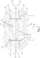
- Fig. 2 is a schematic sectional view illustrating a preferred embodiment of magnetic structure according to the invention.
- the magnetic structure comprises two circular superconducting magnetic coils 20, 25. These coils have an annular shape and are superimposed symmetrically with regard to a median plane of the synchrocyclotron 1.
- the coils of the magnetic structure shown in Fig. 2 have e.g. an outer diameter of 1.370 m and an inner diameter of 1.108 m. These coils are generally named upper coil 20 and lower coil 25, respectively.
- the two coils 20, 50 have a common central axis 50, as indicated in Fig. 2 , going axially through the centres of the coils. This central axis 50 is also forming a central axial axis for the entire magnetic structure.
- the superconducting coils 20, 50 are generating a coil magnetic field in an axial direction, i.e. in a direction parallel with the central axis 50. They comprise e.g. NbTi as superconducting material and are typically operated at 4.5 K, with current densities of about 55.6 A/mm2 for providing a coil magnetic field of about 3.33 Tesla. Alternatively, other superconducting conductor materials can be used such as Nb-3Sn conductors.
- the magnet structure comprises a magnetic yoke structure 30, which consists of several parts. Following main parts of the yoke structure can be distinguished on Fig. 2 : an upper yoke part 31, a lower yoke part 32, a pair of pole parts 33, 34 and a so-called return yoke 35.
- the return yoke 35 is radially arranged around the coils 20, 25.
- the return yoke 35 of Fig. 2 has e.g. an inner diameter of about 1.590 m and a radial thickness of about 0.455 m.
- the superconducting coils 20, 25, together with the magnetic yoke structure generate a combined magnetic field between the two poles of the magnetic structure.
- the prototype referred herein is e.g. a 250 MeV proton synchrocyclotron having a magnetic structure designed for providing a total magnetic field of about 5.6 Tesla for bending protons during a circular acceleration process.
- the entire magnetic structure of such a synchrocyclotron has e.g. a diameter of about 2.5 m and a height of 1.56 m and has a total weight of about 45.000 kg.
- Fig. 3 is an enlarged view of part of the sectional illustration of Fig. 2 .
- the superconducting coils 20, 25 are supported by a coil supporting structure which comprises a mechanical containment structure 27, referred to as bobbin 27, and coil supporting plates 28, 29.
- the bobbin is usually made of aluminium.
- the bobbin 27 is designed and has a shape for withstanding these forces: it has basically an outward wing that is contacting the radial outer part of the two coils and an inner wing in between the coils for withstanding axial attractive forces between the coils.
- Both the outer wing and inner wing of the bobbin have multiple holes for providing access to various parts of the synchrocyclotron.
- the bobbin 27 supporting the two coils 20, 25 is also thermally coupled with the two coils 20, 25.
- the coil supporting structure also comprises an upper 28 and a lower 29 coil supporting plate having an annular shape and which are fixed to the bobbin 27.
- These coil supporting plates 28, 29 are preferably made of stainless steel.
- These coil supporting plates 28, 29 and the bobbin 27 cooperate for encapsulating and holding the coils in place.
- the coils 20, 25 are further surrounded by heat shields 60. Those heat shields are preferably made of an aluminium alloy.
- the upper and lower superconducting coils 20, 25 with the supporting structure 27, 28, 29 are called the cold-mass structure of the magnet structure, as these parts are kept below a temperature where the conductors of the coils 20, 25 are becoming superconducting.
- the whole cold-mass structure is preferably encapsulated in a cryostat 70 that is forming a vacuum chamber for keeping the cold-mass structure under vacuum (see e.g. Fig. 4 , 5 and 6 ).
- the cold-mass structure is cooled by using a dry cryocooler unit.
- dry it is understood that the coils are maintained in a dry condition, i.e. they are not immersed in a cooling liquid (e.g. liquid He). Instead, the cold-mass structure is thermally coupled with one or more dry cryocooler units. These dry cryocooler units are commercially available.
- a through opening in a radial direction is made in the return yoke 35 for receiving a dry cryocooler unit 10.
- the dry cryocooler unit 10 is in a position in which its longitudinal axis is essentially perpendicular to the central axis 50 of the synchrocyclotron 1.
- the cryocooler unit 10 is essentially in a horizontal position.
- the cryocooler unit 10 is preferably at an angle of 90° +/- 5° with respect to the central axis 50 and more preferably at an angle of 90° +/- 2°.
- the refrigeration power will be lower than its nominal refrigeration power, i.e. the refrigeration power is typically reduced by 15%.
- a dry cryocooler having a nominal refrigeration power of 1.5 W in a vertical position will only have a refrigeration power of 1.3 W in a horizontal position.
- four dry cryocoolers units are needed to cool the cold-mass structure of the present example to a temperature of 4.5 K.
- Fig. 2 the horizontal arrangement of the four cryocoolers 10,11,12,13 is shown.
- the opening in the return yoke 35 is configured such that it can receive two superimposed dry cryocooler units as shown in greater detail in Fig. 3 .
- Both cryocooler units 10, 11 are preferably positioned to have their longitudinal axis perpendicular to the central axis 50 and more preferably the two dry cryocooler units are located at the same radial position with respect to the return yoke 35.
- the return flux of the magnetic field remains the same and there is no need to increase the diameter of the cyclotron to compensate for the loss of magnetic flux capacity due to the installation of a second dry cryocooler unit.
- the opening made through the return yoke 35 for receiving two superimposed cryocooler units is rectangular and has a height of about 50 cm and a width of about 29 cm.
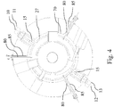
- a second pair of cryocooler units 12, 13 is advantageously separated from a first pair of cryocooler units 10, 11 by a radial angle of 180°.
- the second pair is received through an opening in the return yoke (see e.g. Fig. 2 ), preferably configured for receiving the two cryocooler units superposed at the same radial position.
- a dry cryocooler unit 10, 11 comprises a head part 17, a first stage member 16 and a second stage member 15.
- the head part 17 comprises connection means for making connection with a cooling fluid compressor, e.g. a helium compressor (not shown).
- the first stage member 16 is at an intermediate temperature (for example 50 K) and a lowest temperature of for example 4.2 K is reached at the second stage member 15.
- the second stage member 15 is making a thermal contact with the cold mass structure such that the cold mass structure is cooled to a temperature where the conductors of the coils become superconducting (e.g. 4.5 K).
- the second stage member 15 is making a thermal contact with the outward wing of the bobbin 27 (see e.g. Fig. 4 ).
- each second stage member 15 of each dry cryocooler unit is making a thermal contact with the outward wing of the bobbin 27 of the two coils 20, 25 as shown in Fig. 3 and Fig. 4 .
- the dry cryocooler units that are used for cooling the cold mass structure are at the same time also configured for gradually cooling the current leads of the two coils 20, 25 by making appropriate thermal contacts with the first stage and second stage members. In this way, no dedicated or additional dry cryocooler units need to be installed for cooling the current leads and hence no additional openings need to be made in the yoke structure 30.
- the cold-mass structure is surrounded by a cryostat 70 and a vacuum is created in the cryostat to thermally insulate the cold-mass structure.
- Fig. 5 shows a three dimensional view of the cryostat 70
- Fig. 6 shows its integration into the magnetic yoke structure (for clarity, only the lower part of the yoke 32 and only part of the return yoke 35 are shown in Fig. 6 ).
- This cryostat 70 having a shape of a hollow cylinder is made of stainless steel and has a wall thickness of e.g. 5 mm.
- the pair of horizontally mounted dry cryocooler units 10, 11 on one side of the cryostat and the pair of horizontally mounted dry cryocooler units 12, 13 on the other side of the cryostat are both coupled to the cryostat 70 by means of a radial cryostat vacuum chamber extension 75.
- This radial cryostat vacuum chamber extension 75 houses the first stage member 15 and the second stage member 16 of a pair of dry cryocooler units. In Fig. 5 , solely the head part of the dry cryocooler 10, 11, 12, 13, which extends outside or partly outside the return yoke 35, is visible.
- tension links 80, 90 are used, preferably both in the radial direction and the axial direction. Different types of tension links can be used.
- the preferred tension link is formed by a tied rod. As shown on Fig. 1 and 5 , three radial tension rods 80 and six axial tension rods 90 are attached to the cold-mass structure as supporting means. These tie rods are preferably made of Inconel. Radial tie rods have e.g. a diameter of 14 mm, while the axial tie rods have e.g. a diameter of 8 mm.
- each of the axial 90 and radial 80 tie rods is mounted partially within a hollow tube 85 that is fixed to the exterior of the cryostat 70 as shown in Fig. 4 and Fig. 5 .
- These hollow tubes 85 are part of the cryostat vacuum chamber and are hence vacuum-tight, just as the cryostat body.
- a vacuum is created within the cryostat 70.
- a tube connection piece 86 is advantageously connected to one of the hollow tubes 85, as illustrated in Fig. 1 .
- a vacuum pump can then be connected to this connection piece 86 for creating a vacuum inside the cryostat 70.
- the advantage of this configuration, where a connection piece 86 is connected to a hollow tube 85 enclosing a tie rod 80, is that no additional specific opening must be made in the yoke structure 30 for installing a pumping tube coupled on one end to the cryostat 70 and on the other end to a vacuum pump installed outside the magnetic structure.
- a hollow tube 86 plays the role of being at the same time a housing of a tie rod 80 for supporting the cold mass-structure and a pumping channel for pumping vacuum inside the cryostat 70.
- the present invention has been described with regard to a preferred embodiment of a magnet structure for use in a synchrocyclotron.
- the embodiment described is e.g. capable of providing a magnet field of about 5.6 T and designed for use in a 250 MeV proton synchrocyclotron.
- the dry cryocooler units that are installed through openings in the return yoke of the magnet structure are positioned in an essentially perpendicular position with respect to the central axis 50 of the coils.
- the dry cryocooler units are preferably installed at an angle of 90° +/- 5° with respect to the central axis 50 and more preferably at an angle of 90° +/- 2°.
- the detailed description of this embodiment just illustrates the invention and may not be construed as limiting.
- the dry cryocooler units installed in openings of through the return yoke may not have an orientation perpendicular with respect to the central axis of the synchrocyclotron 1.
- the longitudinal axis of the dry cryocooler unit may define an angle smaller than 90° with the central axis of the synchrocyclotron 1, for example an angle of 80°.
- the invention is of course also applicable to other kinds of circular accelerators (such as e.g. a cyclotron) and to other magnet field strengths.
Landscapes
- Physics & Mathematics (AREA)
- Engineering & Computer Science (AREA)
- Plasma & Fusion (AREA)
- Spectroscopy & Molecular Physics (AREA)
- Optics & Photonics (AREA)
- Particle Accelerators (AREA)
Description
- The invention generally relates to a circular ion accelerator, more particularly to a superconducting synchrocyclotron. More specifically, the invention relates to a magnet structure for a circular ion accelerator, more particularly to a magnetic structure for a superconducting synchrocyclotron.
- A typical magnetic structure of a superconducting synchrocyclotron generally comprises a cold-mass structure including at least two superconducting magnetic coils, i.e. magnetic coils which comprise a material that is superconducting below a nominal temperature, and a bobbin associated with the magnetic coils. A cryostat generally encloses this cold mass structure and forms a vacuum chamber for keeping the cold mass structure under vacuum. The cold mass structure is cooled with one or more dry cryocooler units below the nominal temperature at which the magnetic coils are superconducting. The magnet structure further comprises a magnetic yoke structure surrounding the cryostat. Such a yoke structure generally comprises an upper part, a lower part, a pair of pole parts and a return yoke arranged radially around the magnetic coils.
- US patent
US 7,656,258 describes such a magnetic structure for generating a magnetic field in e.g. a superconducting synchrocyclotron. The magnet structure comprises several dry cryocooler units as shown in Fig. 10 of the referenced patent (units identified with reference number 26) to cool the cold-mass structure (21) below a temperature where the coils become superconducting. A first dry cryocooler unit (26) is positioned vertically on top of the upper part of the yoke (36) and extends vertically through a hole in the upper part of the yoke structure towards the cold mass structure (21). A second cryocooler unit (26) is positioned vertically below the lower part of the yoke structure (36) and extends vertically through a hole in the lower part of the yoke structure. Two additional dry cryocooler units (33) are installed on top of the upper part of the yoke structure and configured for cooling the current leads (37, 58) of the coils (12, 14). Such a vertical orientation of the dry cryocooler units is necessary for reaching the specified nominal refrigeration capacity (e.g. Gifford-McMahon type of cryocooler units). Other types of cryocooler units (e.g. pulse type of cryocooler unit) only operate in a vertical position. - Although the design of the magnetic structure as disclosed in
US 7,656,258 may work in a satisfactory manner, it has nevertheless some disadvantages. - A first disadvantage of the magnetic structure as disclosed in
US 7,656,258 resides in the fact that for each cryocooler unit installed in the upper, respectively lower part of the yoke structure, a corresponding hole must be made in a symmetrical way in the opposite lower part, respectively the opposite upper part of the yoke structure. This symmetry of the holes in the magnetic yoke structure is indeed necessary for warranting the required magnetic field properties. It will be appreciated that these supplementary holes result in an increased machining time when manufacturing the yoke structure.. A great number of holes in the yoke structure also results in a second disadvantage, namely a reduction of the efficiency of the yoke structure and an increase of the magnetic stray field. A third disadvantage is due to the fact that vertically positioned dry cryocooler units increase the height of the accelerator and hence require a larger building with sufficiently high ceilings to house the cyclotron. Moreover, for maintenance purposes, such cyclotrons are opened by removing the upper part of the yoke structure. Hence, before opening the cyclotron, it is necessary to first disconnect the vertically arranged cryocooler units from the cold mass structure, which is a major fourth disadvantage. This fourth disadvantage further results in longer down time periods of cyclotron operation, when the cyclotron must be opened for e.g. maintenance purposes. - The publication of JOONSUN et al: "Design Study of a K22 Prototype Superconducting Cyclotron Magnet", IEEE Transactions on Applied Superconductivity, IEEE Service Center Los Alamitos, CA, US, vol. 20, no. 3, 1 June 2010, pages 192-195, discloses a cryogenic system comprising three 1.5 W GM cryocoolers arranged in separate re-condensing vessels located laterally of the cyclotron. Conduits for evaporated and re-condensed helium pass through a radial opening in the upper half of a return yoke.
- It is an object of the invention to provide a magnetic structure for use in an ion accelerator (e.g. synchrocyclotron) which overcomes or alleviates at least some of the aforementioned problems of prior art magnetic structures.
- This object is achieved by magnet structure in accordance with
claim 1, respectively by a synchrocyclotron comprising such a magnet structure. - A magnet structure for use in a circular ion accelerator comprises a cold-mass structure including superconducting magnetic coils, at least one dry cryocooler unit coupled with the cold-mass structure for cooling the cold-mass structure and a magnetic yoke structure comprising a return yoke configured radially around the coils. In accordance with one aspect of the present invention, the return yoke comprises an opening at a median plane in which the dry cryocooler unit is received so as to be in thermal contact with the cold-mass structure.
- In a preferred embodiment, the dry cryocooler unit is received in the opening in a position essentially perpendicular to a central axis of the magnetic coils.
- Preferably two dry cryocooler units are received in the same opening in the return yoke, wherein they are preferably superimposed at a same radial position. Indeed, by superimposing two cryocooler units at the same radial position with respect to the return yoke, the return flux of the magnetic field remains the same when compared to the use of a single cryocooler unit at the same radial position and hence there is no need to increase the diameter of the cyclotron to compensate for the loss of magnetic flux capacity when installing a second cryocooler unit for increasing the refrigeration capacity.
- In a preferred embodiment, the return yoke comprises two openings spaced by an angle of 180°, wherein at least one cryocooler unit is received in each of these openings. Thus, symmetry of the yoke structure is warranted with a minimum of openings therein. Preferably, two cryocooler units are superimposed in each of these openings.
- The cold-mass structure typically includes a bobbin associated with the superconducting magnetic coils, wherein the at least one cryocooler unit is advantageously in thermal contact with the bobbin.
- The superconducting magnetic coils advantageously include a current lead that is in thermal contact with the cryocooler unit, so that the latter simultaneously cools the bobbin and the current lead. Hence, no dedicated or additional dry cryocooler units must be installed for cooling the current leads and, consequently, no additional openings must be made in the yoke structure
- The cryocooler unit advantageously has a terminal cooling stage member that is in thermal contact with an outward wing of the bobbin, and the outward wing is in contact with a radial outer part of the magnetic coils.
- In a preferred embodiment, the magnet structure has a central axis and a median plane perpendicular to the central axis, and the opening in which the dry cryocooler unit is received is symmetric with regard to the median plane.
- The magnet structure typically comprises a cryostat enclosing the cold-mass structure and forming a vacuum chamber for keeping the cold-mass structure under vacuum. This vacuum chamber advantageously comprises a radial vacuum chamber extension in which at least one cooling stage of the dry cryocooler unit is housed. The latter advantageously includes a head part protruding out of the radial vacuum chamber extension.
- A preferred embodiment of the magnet structure with a vacuum chamber for keeping the cold-mass structure under vacuum further comprises tie rods for supporting the cold-mass structure. Each of the tie rods is advantageously positioned partly within a hollow tube, which extends the vacuum chamber for passing through the yoke structure. At least one of these hollow tubes is advantageously coupled to a vacuum pump for creating a vacuum in the cryostat.
- These and further aspects of the invention will be explained in greater detail by way of example and with reference to the accompanying drawings in which:
- Fig. 1
- is a three-dimensional (3D) view of a synchrocyclotron comprising a magnetic structure according to the invention;
- Fig. 2
- is a schematic sectional view of the magnetic structure according to the invention, the sectional plane being a vertical plane containing the central axis of the synchrocyclotron;
- Fig. 3
- is an enlarged detail of
Fig. 2 showing a configuration of dry cryocooler units in a magnetic structure according to the invention; - Fig.4
- is a schematic sectional view of a synchrocyclotron having a magnetic structure according to the invention, the sectional plane being the median plane of the synchrocyclotron, which is perpendicular to the central axis of the synchrocyclotron;
- Fig. 5
- is a three-dimensional (3D) view of a cryostat for a synchrocyclotron according to the invention; and
- Fig. 6
- is a three-dimensional (3D) view of the cryostat of
Fig. 5 within a magnetic yoke structure. - The figures are not drawn to scale. Generally, identical components are denoted by the same reference numerals in the figures.
-
Fig. 1 shows, as an illustration of the invention, a three dimensional view of a preferred embodiment of asynchrocyclotron 1 comprising a magnetic structure according to the invention. It will be noted that, for the sake of clarity, the representation of thesynchrocyclotron 1 is only schematic, and that not all its parts and details are shown. The major part of the magnetic structure that is visible from the outside of the synchrocyclotron is amagnetic yoke structure 30, which is usually made of ferromagnetic iron. The synchrocyclotron with its magnetic structure is supported on the floor by several feet 5. -
Fig. 2 is a schematic sectional view illustrating a preferred embodiment of magnetic structure according to the invention. The magnetic structure comprises two circular superconductingmagnetic coils synchrocyclotron 1. To fix the ideas, it will be noted that the coils of the magnetic structure shown inFig. 2 have e.g. an outer diameter of 1.370 m and an inner diameter of 1.108 m. These coils are generally namedupper coil 20 andlower coil 25, respectively. The two coils 20, 50 have a commoncentral axis 50, as indicated inFig. 2 , going axially through the centres of the coils. Thiscentral axis 50 is also forming a central axial axis for the entire magnetic structure. - The superconducting coils 20, 50 are generating a coil magnetic field in an axial direction, i.e. in a direction parallel with the
central axis 50. They comprise e.g. NbTi as superconducting material and are typically operated at 4.5 K, with current densities of about 55.6 A/mm2 for providing a coil magnetic field of about 3.33 Tesla. Alternatively, other superconducting conductor materials can be used such as Nb-3Sn conductors. - As mentioned above, the magnet structure comprises a
magnetic yoke structure 30, which consists of several parts. Following main parts of the yoke structure can be distinguished onFig. 2 : anupper yoke part 31, alower yoke part 32, a pair ofpole parts return yoke 35. Thereturn yoke 35 is radially arranged around thecoils return yoke 35 ofFig. 2 has e.g. an inner diameter of about 1.590 m and a radial thickness of about 0.455 m. - The superconducting coils 20, 25, together with the magnetic yoke structure generate a combined magnetic field between the two poles of the magnetic structure. The prototype referred herein is e.g. a 250 MeV proton synchrocyclotron having a magnetic structure designed for providing a total magnetic field of about 5.6 Tesla for bending protons during a circular acceleration process. To fix the ideas, it will be noted that the entire magnetic structure of such a synchrocyclotron has e.g. a diameter of about 2.5 m and a height of 1.56 m and has a total weight of about 45.000 kg.
-
Fig. 3 is an enlarged view of part of the sectional illustration ofFig. 2 . The superconducting coils 20, 25 are supported by a coil supporting structure which comprises amechanical containment structure 27, referred to asbobbin 27, andcoil supporting plates lower coils bobbin 27 is designed and has a shape for withstanding these forces: it has basically an outward wing that is contacting the radial outer part of the two coils and an inner wing in between the coils for withstanding axial attractive forces between the coils. Both the outer wing and inner wing of the bobbin have multiple holes for providing access to various parts of the synchrocyclotron. Thebobbin 27 supporting the twocoils coils bobbin 27. Thesecoil supporting plates coil supporting plates bobbin 27 cooperate for encapsulating and holding the coils in place. Thecoils heat shields 60. Those heat shields are preferably made of an aluminium alloy. The upper and lowersuperconducting coils structure coils cryostat 70 that is forming a vacuum chamber for keeping the cold-mass structure under vacuum (see e.g.Fig. 4 ,5 and 6 ). - The cold-mass structure is cooled by using a dry cryocooler unit. With the wording "dry" it is understood that the coils are maintained in a dry condition, i.e. they are not immersed in a cooling liquid (e.g. liquid He). Instead, the cold-mass structure is thermally coupled with one or more dry cryocooler units. These dry cryocooler units are commercially available.
- As shown in
Fig. 2 andFig. 3 , a through opening in a radial direction is made in thereturn yoke 35 for receiving adry cryocooler unit 10. In this example, thedry cryocooler unit 10 is in a position in which its longitudinal axis is essentially perpendicular to thecentral axis 50 of thesynchrocyclotron 1. In other words, if thesynchrocyclotron 1 is positioned on the floor on its feet 5, as shown inFig. 1 , thedry cryocooler 10 unit is essentially in a horizontal position. When positioning adry cryocooler unit 10 perpendicular to thecentral axis 50, there is a certain tolerance with respect to this orientation. In the example presented, thecryocooler unit 10 is preferably at an angle of 90° +/- 5° with respect to thecentral axis 50 and more preferably at an angle of 90° +/- 2°. - When the dry cryocooler unit (e.g. a dry cryocooler unit of the Gifford-McMahon type) is in such a horizontal position with respect to the floor, the refrigeration power will be lower than its nominal refrigeration power, i.e. the refrigeration power is typically reduced by 15%. For example, a dry cryocooler having a nominal refrigeration power of 1.5 W in a vertical position will only have a refrigeration power of 1.3 W in a horizontal position. With a refrigeration power of 1.3 W per cryocooler unit and with a synchrocyclotron in operation (i.e. producing beam), four dry cryocoolers units are needed to cool the cold-mass structure of the present example to a temperature of 4.5 K. In
Fig. 2 , the horizontal arrangement of the fourcryocoolers - Preferably, the opening in the
return yoke 35 is configured such that it can receive two superimposed dry cryocooler units as shown in greater detail inFig. 3 . Bothcryocooler units central axis 50 and more preferably the two dry cryocooler units are located at the same radial position with respect to thereturn yoke 35. In this way, the return flux of the magnetic field remains the same and there is no need to increase the diameter of the cyclotron to compensate for the loss of magnetic flux capacity due to the installation of a second dry cryocooler unit. To fix the ideas, it will be noted that the opening made through thereturn yoke 35 for receiving two superimposed cryocooler units is rectangular and has a height of about 50 cm and a width of about 29 cm. - As illustrated in
Fig. 4 , a second pair ofcryocooler units cryocooler units Fig. 2 ), preferably configured for receiving the two cryocooler units superposed at the same radial position. - Typically and as shown in
Fig. 3 , adry cryocooler unit first stage member 16 and asecond stage member 15. The head part 17 comprises connection means for making connection with a cooling fluid compressor, e.g. a helium compressor (not shown). Thefirst stage member 16 is at an intermediate temperature (for example 50 K) and a lowest temperature of for example 4.2 K is reached at thesecond stage member 15. Thesecond stage member 15 is making a thermal contact with the cold mass structure such that the cold mass structure is cooled to a temperature where the conductors of the coils become superconducting (e.g. 4.5 K). More specifically, thesecond stage member 15 is making a thermal contact with the outward wing of the bobbin 27 (see e.g.Fig. 4 ). As in this preferred magnetic structure, two pair of superimposed dry cryocooler units are used, eachsecond stage member 15 of each dry cryocooler unit is making a thermal contact with the outward wing of thebobbin 27 of the twocoils Fig. 3 andFig. 4 . - The dry cryocooler units that are used for cooling the cold mass structure are at the same time also configured for gradually cooling the current leads of the two
coils yoke structure 30. - As discussed above, the cold-mass structure is surrounded by a
cryostat 70 and a vacuum is created in the cryostat to thermally insulate the cold-mass structure. -
Fig. 5 shows a three dimensional view of thecryostat 70, whereasFig. 6 shows its integration into the magnetic yoke structure (for clarity, only the lower part of theyoke 32 and only part of thereturn yoke 35 are shown inFig. 6 ). Thiscryostat 70 having a shape of a hollow cylinder is made of stainless steel and has a wall thickness of e.g. 5 mm. The pair of horizontally mounteddry cryocooler units dry cryocooler units cryostat 70 by means of a radial cryostatvacuum chamber extension 75. This radial cryostatvacuum chamber extension 75 houses thefirst stage member 15 and thesecond stage member 16 of a pair of dry cryocooler units. InFig. 5 , solely the head part of thedry cryocooler return yoke 35, is visible. - The heavy cold-mass structure, having a weight of about 4.300kg, must be supported inside the
cryostat 70. For this purpose, tension links 80, 90 are used, preferably both in the radial direction and the axial direction. Different types of tension links can be used. The preferred tension link is formed by a tied rod. As shown onFig. 1 and5 , threeradial tension rods 80 and sixaxial tension rods 90 are attached to the cold-mass structure as supporting means. These tie rods are preferably made of Inconel. Radial tie rods have e.g. a diameter of 14 mm, while the axial tie rods have e.g. a diameter of 8 mm. From the sixaxial tie rods 90, three pass through theupper yoke part 31 and three pass through thelower yoke part 32. The threeradial tie rods 80 pass through thereturn yoke 35. For passing through the various parts of theyoke structure 30, each of the axial 90 and radial 80 tie rods is mounted partially within ahollow tube 85 that is fixed to the exterior of thecryostat 70 as shown inFig. 4 andFig. 5 . Thesehollow tubes 85 are part of the cryostat vacuum chamber and are hence vacuum-tight, just as the cryostat body. - As mentioned above, a vacuum is created within the
cryostat 70. To create this vacuum, atube connection piece 86 is advantageously connected to one of thehollow tubes 85, as illustrated inFig. 1 . A vacuum pump can then be connected to thisconnection piece 86 for creating a vacuum inside thecryostat 70. The advantage of this configuration, where aconnection piece 86 is connected to ahollow tube 85 enclosing atie rod 80, is that no additional specific opening must be made in theyoke structure 30 for installing a pumping tube coupled on one end to thecryostat 70 and on the other end to a vacuum pump installed outside the magnetic structure. With this configuration, ahollow tube 86 plays the role of being at the same time a housing of atie rod 80 for supporting the cold mass-structure and a pumping channel for pumping vacuum inside thecryostat 70. - The present invention has been described with regard to a preferred embodiment of a magnet structure for use in a synchrocyclotron. The embodiment described is e.g. capable of providing a magnet field of about 5.6 T and designed for use in a 250 MeV proton synchrocyclotron. The dry cryocooler units that are installed through openings in the return yoke of the magnet structure are positioned in an essentially perpendicular position with respect to the
central axis 50 of the coils. As discussed above, the dry cryocooler units are preferably installed at an angle of 90° +/- 5° with respect to thecentral axis 50 and more preferably at an angle of 90° +/- 2°. However, the detailed description of this embodiment just illustrates the invention and may not be construed as limiting. - More specifically, in alternative embodiments, the dry cryocooler units installed in openings of through the return yoke may not have an orientation perpendicular with respect to the central axis of the
synchrocyclotron 1. Thus, the longitudinal axis of the dry cryocooler unit may define an angle smaller than 90° with the central axis of thesynchrocyclotron 1, for example an angle of 80°. The invention is of course also applicable to other kinds of circular accelerators (such as e.g. a cyclotron) and to other magnet field strengths. - More generally, it will be appreciated by persons skilled in the art that the present invention is not limited by what has been particularly shown and/or described hereinabove. The scope of the invention is defined by the claims.
- Reference numerals in the claims do not limit their protective scope.
- Use of the verbs "to comprise", "to include", "to be composed of", or any other variant, as well as their respective conjugations, does not exclude the presence of parts other than those stated.
- Use of the article "a", "an" or "the" preceding an element does not exclude the presence of a plurality of such elements.
-
- 01
- synchrocyclotron
- 05
- foot
- 10,11
- first pair of cryocooler units
- 12,13
- second pair of cryocooler units
- 15
- second stage member
- 16
- first stage member
- 17
- head part
- 20
- superconducting magnetic coil (upper coil)
- 25
- superconducting magnetic coil (lower coil)
- 27
- bobbin
- 28,29
- coil supporting plates
- 30
- magnetic yoke structure
- 31
- upper yoke part
- 32
- lower yoke part
- 33,34
- pair of pole parts
- 35
- return yoke
- 50
- common central axis
- 60
- heat shield
- 70
- cryostat
- 75
- cryostat vacuum chamber extension
- 80
- radial tension rod
- 85
- hollow tube
- 86
- tube connection piece
- 90
- axial tension rod
Claims (15)
- A magnet structure for use in a circular ion accelerator comprising:- a cold-mass structure including superconducting magnetic coils (20,25);- at least one dry cryocooler unit (10,11,12,13) coupled with said cold-mass structure for cooling said cold-mass structure; and- a magnetic yoke structure (30) including a return yoke (35) configured radially around said coils (20,25);characterized in that said return yoke (35) comprises an opening at a median plane in which said dry cryocooler unit (10,11,12,13) is received so as to be in thermal contact with said cold-mass structure.
- The magnet structure according to claim 1, wherein said dry cryocooler unit (10,11,12,13) is received in said opening in a position essentially perpendicular to a central axis (50) of said magnetic coils (20,25).
- The magnet structure according to any one of the preceding claims, wherein two dry cryocooler units (10, 11) (12, 13) are received in said opening in said return yoke (35).
- The magnet structure according to claim 3, wherein said two dry cryocooler units (10, 11) (12, 13) are superimposed at a same radial position.
- The magnet structure according to any one of the preceding claims, comprising two openings spaced by an angle of 180° in said return yoke (35), wherein at least one cryocooler unit (10,11,12,13) is received in each of said openings.
- The magnet structure according to claim 5, wherein two cryocooler units (10,11) (12,13) are superimposed in each of said openings.
- The magnet structure according to any one of the preceding claims, wherein said cold-mass structure includes a bobbin associated with said superconducting magnetic coils (20,25), and said cryocooler unit (10,11,12,13) is in thermal contact with said bobbin (27) .
- The magnet structure according to claim 7, wherein said superconducting magnetic coils (20,25) include a current lead that is in thermal contact with said cryocooler unit (10,11,12,13), so that the latter simultaneously cools said bobbin (27) and said current lead.
- The magnet structure according to claim 7 or 8, wherein said cryocooler unit (10,11,12,13) has a terminal cooling stage member (15) that is in thermal contact with an outward wing of said bobbin (27), and said outward wing is in contact with a radial outer part of said magnetic coils (20, 25).
- The magnet structure according to any one of the preceding claims, wherein said magnet structure has a central axis and a median plane perpendicular to said central axis, and said opening in which said dry cryocooler unit (10,11,12,13) is received is symmetric with regard to said median plane.
- The magnet structure according to any one of the preceding claims, comprising a cryostat (70) enclosing said cold-mass structure and forming a vacuum chamber for keeping said cold-mass structure under vacuum, said vacuum chamber comprising a radial vacuum chamber extension (75), and said dry cryocooler unit (10,11,12,13) including at least one cooling stage housed in said vacuum chamber extension (75), and a head part (17) with connection means protruding out of said radial vacuum chamber extension (75).
- The magnet structure according to claim 11 or 12, further comprising tie rods for supporting said cold-mass structure, each of said tie rods being positioned partly within a hollow tube (85), which extends the vacuum chamber for passing through said yoke structure (30).
- The magnet structure according to claim 13, wherein at least one of said hollow tubes (85) is coupled to a vacuum pump for creating a vacuum in said cryostat (70).
- The magnet structure as claimed in any one of the preceding claims, wherein:said cold mass structure includes at least two coils (20, 25) comprising a material being superconducting below a nominal temperature, said coils (20,25) being configured for having a common central axis (50); and a bobbin (27) for supporting said two coils (20,25);and said magnet structure further includes:
a cryostat (70) enclosing the cold-mass structure and forming a vacuum chamber for keeping said cold-mass structure under vacuum, wherein the magnetic yoke structure (30) surrounds said cryostat (70). - A synchrocyclotron comprising a magnet structure according to any one of the previous claims.
Priority Applications (1)
| Application Number | Priority Date | Filing Date | Title |
|---|---|---|---|
| EP11776152.8A EP2633742B1 (en) | 2010-10-26 | 2011-10-25 | Magnetic structure for circular ion accelerator |
Applications Claiming Priority (3)
| Application Number | Priority Date | Filing Date | Title |
|---|---|---|---|
| EP10188946 | 2010-10-26 | ||
| PCT/EP2011/068691 WO2012055890A1 (en) | 2010-10-26 | 2011-10-25 | Magnetic structure for circular ion accelerator |
| EP11776152.8A EP2633742B1 (en) | 2010-10-26 | 2011-10-25 | Magnetic structure for circular ion accelerator |
Publications (2)
| Publication Number | Publication Date |
|---|---|
| EP2633742A1 EP2633742A1 (en) | 2013-09-04 |
| EP2633742B1 true EP2633742B1 (en) | 2018-08-15 |
Family
ID=43978034
Family Applications (1)
| Application Number | Title | Priority Date | Filing Date |
|---|---|---|---|
| EP11776152.8A Active EP2633742B1 (en) | 2010-10-26 | 2011-10-25 | Magnetic structure for circular ion accelerator |
Country Status (4)
| Country | Link |
|---|---|
| US (1) | US9271385B2 (en) |
| EP (1) | EP2633742B1 (en) |
| CN (1) | CN103370992B (en) |
| WO (1) | WO2012055890A1 (en) |
Families Citing this family (22)
| Publication number | Priority date | Publication date | Assignee | Title |
|---|---|---|---|---|
| JP2013144099A (en) * | 2011-12-12 | 2013-07-25 | Toshiba Corp | Magnetic resonance imaging apparatus |
| JP2014038738A (en) * | 2012-08-13 | 2014-02-27 | Sumitomo Heavy Ind Ltd | Cyclotron |
| EP2785154B1 (en) * | 2013-03-29 | 2015-10-21 | Ion Beam Applications S.A. | Compact superconducting cyclotron |
| US8791656B1 (en) * | 2013-05-31 | 2014-07-29 | Mevion Medical Systems, Inc. | Active return system |
| ES2768659T3 (en) | 2013-09-27 | 2020-06-23 | Mevion Medical Systems Inc | Particle beam scanning |
| US10675487B2 (en) | 2013-12-20 | 2020-06-09 | Mevion Medical Systems, Inc. | Energy degrader enabling high-speed energy switching |
| US9962560B2 (en) | 2013-12-20 | 2018-05-08 | Mevion Medical Systems, Inc. | Collimator and energy degrader |
| US9661736B2 (en) | 2014-02-20 | 2017-05-23 | Mevion Medical Systems, Inc. | Scanning system for a particle therapy system |
| US10786689B2 (en) | 2015-11-10 | 2020-09-29 | Mevion Medical Systems, Inc. | Adaptive aperture |
| CN105848403B (en) * | 2016-06-15 | 2018-01-30 | 中国工程物理研究院流体物理研究所 | Internal ion-source cyclotron |
| WO2018009779A1 (en) | 2016-07-08 | 2018-01-11 | Mevion Medical Systems, Inc. | Treatment planning |
| CN106163071B (en) * | 2016-07-29 | 2018-08-24 | 中国原子能科学研究院 | The suspension and method of a kind of adjustment superconducting cyclotron magnetic field first harmonic |
| CN106132066B (en) * | 2016-07-29 | 2018-07-06 | 中国原子能科学研究院 | A kind of sealing structure of the cryostat of superconducting cyclotron |
| US11103730B2 (en) | 2017-02-23 | 2021-08-31 | Mevion Medical Systems, Inc. | Automated treatment in particle therapy |
| JP6909636B2 (en) * | 2017-05-23 | 2021-07-28 | 住友重機械工業株式会社 | Superconducting cyclotron and manufacturing method of superconducting cyclotron |
| WO2019006253A1 (en) | 2017-06-30 | 2019-01-03 | Mevion Medical Systems, Inc. | Configurable collimator controlled using linear motors |
| JP6780906B2 (en) * | 2017-09-22 | 2020-11-04 | 三菱電機株式会社 | Electromagnet for accelerator |
| JP7002952B2 (en) * | 2018-01-29 | 2022-01-20 | 株式会社日立製作所 | A circular accelerator, a particle beam therapy system equipped with a circular accelerator, and how to operate the circular accelerator |
| CN109792834B (en) * | 2018-12-17 | 2021-05-28 | 新里程医用加速器(无锡)有限公司 | Heat sink for medical accelerator |
| EP3934752A1 (en) | 2019-03-08 | 2022-01-12 | Mevion Medical Systems, Inc. | Delivery of radiation by column and generating a treatment plan therefor |
| CN111341518B (en) * | 2020-02-28 | 2021-11-09 | 合肥中科离子医学技术装备有限公司 | Aging exercise device for magnetic field environment |
| JP7648426B2 (en) * | 2021-04-08 | 2025-03-18 | 住友重機械工業株式会社 | Superconducting magnet devices and cyclotrons |
Family Cites Families (12)
| Publication number | Priority date | Publication date | Assignee | Title |
|---|---|---|---|---|
| US4641057A (en) | 1985-01-23 | 1987-02-03 | Board Of Trustees Operating Michigan State University | Superconducting synchrocyclotron |
| WO2007130164A2 (en) | 2006-01-19 | 2007-11-15 | Massachusetts Institute Of Technology | High-field superconducting synchrocyclotron |
| US7656258B1 (en) * | 2006-01-19 | 2010-02-02 | Massachusetts Institute Of Technology | Magnet structure for particle acceleration |
| US8581523B2 (en) * | 2007-11-30 | 2013-11-12 | Mevion Medical Systems, Inc. | Interrupted particle source |
| US7940894B2 (en) * | 2008-05-22 | 2011-05-10 | Vladimir Balakin | Elongated lifetime X-ray method and apparatus used in conjunction with a charged particle cancer therapy system |
| GB2467595B (en) * | 2009-02-09 | 2011-08-24 | Tesla Engineering Ltd | Cooling systems and methods |
| US8374306B2 (en) * | 2009-06-26 | 2013-02-12 | General Electric Company | Isotope production system with separated shielding |
| BE1019557A3 (en) | 2010-10-27 | 2012-08-07 | Ion Beam Applic Sa | Synchrocyclotron. |
| US8525447B2 (en) * | 2010-11-22 | 2013-09-03 | Massachusetts Institute Of Technology | Compact cold, weak-focusing, superconducting cyclotron |
| JP5665721B2 (en) * | 2011-02-28 | 2015-02-04 | 三菱電機株式会社 | Circular accelerator and operation method of circular accelerator |
| US8558485B2 (en) * | 2011-07-07 | 2013-10-15 | Ionetix Corporation | Compact, cold, superconducting isochronous cyclotron |
| US8581525B2 (en) * | 2012-03-23 | 2013-11-12 | Massachusetts Institute Of Technology | Compensated precessional beam extraction for cyclotrons |
-
2011
- 2011-10-25 EP EP11776152.8A patent/EP2633742B1/en active Active
- 2011-10-25 US US13/881,315 patent/US9271385B2/en active Active
- 2011-10-25 WO PCT/EP2011/068691 patent/WO2012055890A1/en not_active Ceased
- 2011-10-25 CN CN201180058663.3A patent/CN103370992B/en active Active
Non-Patent Citations (1)
| Title |
|---|
| None * |
Also Published As
| Publication number | Publication date |
|---|---|
| US9271385B2 (en) | 2016-02-23 |
| US20130270451A1 (en) | 2013-10-17 |
| CN103370992B (en) | 2016-12-07 |
| EP2633742A1 (en) | 2013-09-04 |
| CN103370992A (en) | 2013-10-23 |
| WO2012055890A1 (en) | 2012-05-03 |
Similar Documents
| Publication | Publication Date | Title |
|---|---|---|
| US9271385B2 (en) | Magnetic structure for circular ion accelerator | |
| EP3305038B1 (en) | Isochronous cyclotron with superconducting flutter coils and non-magnetic reinforcement | |
| Lvovsky et al. | Novel technologies and configurations of superconducting magnets for MRI | |
| CN102308676B (en) | Cooling systems and methods | |
| CN102349119B (en) | Method and apparatus for electrical, mechanical and thermal isolation of superconductive magnets | |
| CN106098290B (en) | Superconducting magnet | |
| Chouhan et al. | The superferric cyclotron gas stopper magnet design and fabrication | |
| US6323749B1 (en) | MRI with superconducting coil | |
| Vianna et al. | Conceptual design of a C-shaped 6.4 T superconducting dipole magnet | |
| Mito et al. | Engineering design of the Mini-RT device | |
| Valentinov et al. | New superconducting wigglers for KSRS | |
| Khrushchev et al. | 3.5 Tesla 49-pole superconducting wiggler for DLS | |
| Kellams et al. | Superconducting sector dipole for a strong focusing cyclotron | |
| Semba et al. | Design and manufacture of superconducting magnet for the wiggler in SAGA-LS | |
| Taylor et al. | A final-focus magnet system for PEP-II | |
| Wang et al. | Superconducting magnets and cooling system in BEPCII | |
| Kashikhin et al. | Magnetic designs and field quality of Nb/sub 3/Sn accelerator magnets | |
| Kim et al. | Superconducting magnet system of in-flight separator for a heavy ion accelerator planned in Korea | |
| Green | A large superconducting thin solenoid for the STAR experiment at RHIC | |
| Agapov et al. | Superconducting magnetic system of the fast cycling intermediate energy ion synchrotron | |
| Hitz et al. | Design study of a hybrid ECRIS | |
| Green et al. | Magnet and cryostat configurations for a multi-port quadrupole array | |
| Lesmond | Superconducting magnet activities at CEN Saclay | |
| Taylor et al. | A final-focus magnet for PEP-II | |
| Caspi | T2 working group summary report |
Legal Events
| Date | Code | Title | Description |
|---|---|---|---|
| PUAI | Public reference made under article 153(3) epc to a published international application that has entered the european phase |
Free format text: ORIGINAL CODE: 0009012 |
|
| 17P | Request for examination filed |
Effective date: 20130424 |
|
| AK | Designated contracting states |
Kind code of ref document: A1 Designated state(s): AL AT BE BG CH CY CZ DE DK EE ES FI FR GB GR HR HU IE IS IT LI LT LU LV MC MK MT NL NO PL PT RO RS SE SI SK SM TR |
|
| DAX | Request for extension of the european patent (deleted) | ||
| GRAP | Despatch of communication of intention to grant a patent |
Free format text: ORIGINAL CODE: EPIDOSNIGR1 |
|
| INTG | Intention to grant announced |
Effective date: 20180313 |
|
| GRAS | Grant fee paid |
Free format text: ORIGINAL CODE: EPIDOSNIGR3 |
|
| GRAA | (expected) grant |
Free format text: ORIGINAL CODE: 0009210 |
|
| AK | Designated contracting states |
Kind code of ref document: B1 Designated state(s): AL AT BE BG CH CY CZ DE DK EE ES FI FR GB GR HR HU IE IS IT LI LT LU LV MC MK MT NL NO PL PT RO RS SE SI SK SM TR |
|
| REG | Reference to a national code |
Ref country code: CH Ref legal event code: EP Ref country code: GB Ref legal event code: FG4D Ref country code: AT Ref legal event code: REF Ref document number: 1031315 Country of ref document: AT Kind code of ref document: T Effective date: 20180815 |
|
| REG | Reference to a national code |
Ref country code: IE Ref legal event code: FG4D |
|
| REG | Reference to a national code |
Ref country code: DE Ref legal event code: R096 Ref document number: 602011051102 Country of ref document: DE |
|
| REG | Reference to a national code |
Ref country code: FR Ref legal event code: PLFP Year of fee payment: 8 |
|
| RAP2 | Party data changed (patent owner data changed or rights of a patent transferred) |
Owner name: ION BEAM APPLICATIONS S.A. |
|
| REG | Reference to a national code |
Ref country code: NL Ref legal event code: MP Effective date: 20180815 |
|
| REG | Reference to a national code |
Ref country code: LT Ref legal event code: MG4D |
|
| REG | Reference to a national code |
Ref country code: AT Ref legal event code: MK05 Ref document number: 1031315 Country of ref document: AT Kind code of ref document: T Effective date: 20180815 |
|
| PG25 | Lapsed in a contracting state [announced via postgrant information from national office to epo] |
Ref country code: FI Free format text: LAPSE BECAUSE OF FAILURE TO SUBMIT A TRANSLATION OF THE DESCRIPTION OR TO PAY THE FEE WITHIN THE PRESCRIBED TIME-LIMIT Effective date: 20180815 Ref country code: SE Free format text: LAPSE BECAUSE OF FAILURE TO SUBMIT A TRANSLATION OF THE DESCRIPTION OR TO PAY THE FEE WITHIN THE PRESCRIBED TIME-LIMIT Effective date: 20180815 Ref country code: NO Free format text: LAPSE BECAUSE OF FAILURE TO SUBMIT A TRANSLATION OF THE DESCRIPTION OR TO PAY THE FEE WITHIN THE PRESCRIBED TIME-LIMIT Effective date: 20181115 Ref country code: BG Free format text: LAPSE BECAUSE OF FAILURE TO SUBMIT A TRANSLATION OF THE DESCRIPTION OR TO PAY THE FEE WITHIN THE PRESCRIBED TIME-LIMIT Effective date: 20181115 Ref country code: NL Free format text: LAPSE BECAUSE OF FAILURE TO SUBMIT A TRANSLATION OF THE DESCRIPTION OR TO PAY THE FEE WITHIN THE PRESCRIBED TIME-LIMIT Effective date: 20180815 Ref country code: AT Free format text: LAPSE BECAUSE OF FAILURE TO SUBMIT A TRANSLATION OF THE DESCRIPTION OR TO PAY THE FEE WITHIN THE PRESCRIBED TIME-LIMIT Effective date: 20180815 Ref country code: IS Free format text: LAPSE BECAUSE OF FAILURE TO SUBMIT A TRANSLATION OF THE DESCRIPTION OR TO PAY THE FEE WITHIN THE PRESCRIBED TIME-LIMIT Effective date: 20181215 Ref country code: RS Free format text: LAPSE BECAUSE OF FAILURE TO SUBMIT A TRANSLATION OF THE DESCRIPTION OR TO PAY THE FEE WITHIN THE PRESCRIBED TIME-LIMIT Effective date: 20180815 Ref country code: GR Free format text: LAPSE BECAUSE OF FAILURE TO SUBMIT A TRANSLATION OF THE DESCRIPTION OR TO PAY THE FEE WITHIN THE PRESCRIBED TIME-LIMIT Effective date: 20181116 Ref country code: LT Free format text: LAPSE BECAUSE OF FAILURE TO SUBMIT A TRANSLATION OF THE DESCRIPTION OR TO PAY THE FEE WITHIN THE PRESCRIBED TIME-LIMIT Effective date: 20180815 |
|
| PG25 | Lapsed in a contracting state [announced via postgrant information from national office to epo] |
Ref country code: HR Free format text: LAPSE BECAUSE OF FAILURE TO SUBMIT A TRANSLATION OF THE DESCRIPTION OR TO PAY THE FEE WITHIN THE PRESCRIBED TIME-LIMIT Effective date: 20180815 Ref country code: LV Free format text: LAPSE BECAUSE OF FAILURE TO SUBMIT A TRANSLATION OF THE DESCRIPTION OR TO PAY THE FEE WITHIN THE PRESCRIBED TIME-LIMIT Effective date: 20180815 Ref country code: AL Free format text: LAPSE BECAUSE OF FAILURE TO SUBMIT A TRANSLATION OF THE DESCRIPTION OR TO PAY THE FEE WITHIN THE PRESCRIBED TIME-LIMIT Effective date: 20180815 |
|
| PG25 | Lapsed in a contracting state [announced via postgrant information from national office to epo] |
Ref country code: ES Free format text: LAPSE BECAUSE OF FAILURE TO SUBMIT A TRANSLATION OF THE DESCRIPTION OR TO PAY THE FEE WITHIN THE PRESCRIBED TIME-LIMIT Effective date: 20180815 Ref country code: CZ Free format text: LAPSE BECAUSE OF FAILURE TO SUBMIT A TRANSLATION OF THE DESCRIPTION OR TO PAY THE FEE WITHIN THE PRESCRIBED TIME-LIMIT Effective date: 20180815 Ref country code: RO Free format text: LAPSE BECAUSE OF FAILURE TO SUBMIT A TRANSLATION OF THE DESCRIPTION OR TO PAY THE FEE WITHIN THE PRESCRIBED TIME-LIMIT Effective date: 20180815 Ref country code: EE Free format text: LAPSE BECAUSE OF FAILURE TO SUBMIT A TRANSLATION OF THE DESCRIPTION OR TO PAY THE FEE WITHIN THE PRESCRIBED TIME-LIMIT Effective date: 20180815 Ref country code: PL Free format text: LAPSE BECAUSE OF FAILURE TO SUBMIT A TRANSLATION OF THE DESCRIPTION OR TO PAY THE FEE WITHIN THE PRESCRIBED TIME-LIMIT Effective date: 20180815 |
|
| REG | Reference to a national code |
Ref country code: DE Ref legal event code: R097 Ref document number: 602011051102 Country of ref document: DE |
|
| PG25 | Lapsed in a contracting state [announced via postgrant information from national office to epo] |
Ref country code: DK Free format text: LAPSE BECAUSE OF FAILURE TO SUBMIT A TRANSLATION OF THE DESCRIPTION OR TO PAY THE FEE WITHIN THE PRESCRIBED TIME-LIMIT Effective date: 20180815 Ref country code: SM Free format text: LAPSE BECAUSE OF FAILURE TO SUBMIT A TRANSLATION OF THE DESCRIPTION OR TO PAY THE FEE WITHIN THE PRESCRIBED TIME-LIMIT Effective date: 20180815 Ref country code: SK Free format text: LAPSE BECAUSE OF FAILURE TO SUBMIT A TRANSLATION OF THE DESCRIPTION OR TO PAY THE FEE WITHIN THE PRESCRIBED TIME-LIMIT Effective date: 20180815 |
|
| REG | Reference to a national code |
Ref country code: CH Ref legal event code: PL |
|
| PLBE | No opposition filed within time limit |
Free format text: ORIGINAL CODE: 0009261 |
|
| STAA | Information on the status of an ep patent application or granted ep patent |
Free format text: STATUS: NO OPPOSITION FILED WITHIN TIME LIMIT |
|
| PG25 | Lapsed in a contracting state [announced via postgrant information from national office to epo] |
Ref country code: MC Free format text: LAPSE BECAUSE OF FAILURE TO SUBMIT A TRANSLATION OF THE DESCRIPTION OR TO PAY THE FEE WITHIN THE PRESCRIBED TIME-LIMIT Effective date: 20180815 Ref country code: LU Free format text: LAPSE BECAUSE OF NON-PAYMENT OF DUE FEES Effective date: 20181025 |
|
| 26N | No opposition filed |
Effective date: 20190516 |
|
| REG | Reference to a national code |
Ref country code: IE Ref legal event code: MM4A |
|
| PG25 | Lapsed in a contracting state [announced via postgrant information from national office to epo] |
Ref country code: SI Free format text: LAPSE BECAUSE OF FAILURE TO SUBMIT A TRANSLATION OF THE DESCRIPTION OR TO PAY THE FEE WITHIN THE PRESCRIBED TIME-LIMIT Effective date: 20180815 Ref country code: CH Free format text: LAPSE BECAUSE OF NON-PAYMENT OF DUE FEES Effective date: 20181031 Ref country code: LI Free format text: LAPSE BECAUSE OF NON-PAYMENT OF DUE FEES Effective date: 20181031 |
|
| PG25 | Lapsed in a contracting state [announced via postgrant information from national office to epo] |
Ref country code: IE Free format text: LAPSE BECAUSE OF NON-PAYMENT OF DUE FEES Effective date: 20181025 |
|
| PG25 | Lapsed in a contracting state [announced via postgrant information from national office to epo] |
Ref country code: MT Free format text: LAPSE BECAUSE OF NON-PAYMENT OF DUE FEES Effective date: 20181025 |
|
| PG25 | Lapsed in a contracting state [announced via postgrant information from national office to epo] |
Ref country code: TR Free format text: LAPSE BECAUSE OF FAILURE TO SUBMIT A TRANSLATION OF THE DESCRIPTION OR TO PAY THE FEE WITHIN THE PRESCRIBED TIME-LIMIT Effective date: 20180815 |
|
| PG25 | Lapsed in a contracting state [announced via postgrant information from national office to epo] |
Ref country code: PT Free format text: LAPSE BECAUSE OF FAILURE TO SUBMIT A TRANSLATION OF THE DESCRIPTION OR TO PAY THE FEE WITHIN THE PRESCRIBED TIME-LIMIT Effective date: 20180815 |
|
| PG25 | Lapsed in a contracting state [announced via postgrant information from national office to epo] |
Ref country code: MK Free format text: LAPSE BECAUSE OF NON-PAYMENT OF DUE FEES Effective date: 20180815 Ref country code: HU Free format text: LAPSE BECAUSE OF FAILURE TO SUBMIT A TRANSLATION OF THE DESCRIPTION OR TO PAY THE FEE WITHIN THE PRESCRIBED TIME-LIMIT; INVALID AB INITIO Effective date: 20111025 Ref country code: CY Free format text: LAPSE BECAUSE OF FAILURE TO SUBMIT A TRANSLATION OF THE DESCRIPTION OR TO PAY THE FEE WITHIN THE PRESCRIBED TIME-LIMIT Effective date: 20180815 |
|
| P01 | Opt-out of the competence of the unified patent court (upc) registered |
Effective date: 20230517 |
|
| PGFP | Annual fee paid to national office [announced via postgrant information from national office to epo] |
Ref country code: DE Payment date: 20251029 Year of fee payment: 15 |
|
| PGFP | Annual fee paid to national office [announced via postgrant information from national office to epo] |
Ref country code: GB Payment date: 20251027 Year of fee payment: 15 |
|
| PGFP | Annual fee paid to national office [announced via postgrant information from national office to epo] |
Ref country code: IT Payment date: 20251021 Year of fee payment: 15 |
|
| PGFP | Annual fee paid to national office [announced via postgrant information from national office to epo] |
Ref country code: FR Payment date: 20251027 Year of fee payment: 15 |
|
| PGFP | Annual fee paid to national office [announced via postgrant information from national office to epo] |
Ref country code: BE Payment date: 20251027 Year of fee payment: 15 |