EP2633296B1 - Chemical sensing device and measuring method - Google Patents
Chemical sensing device and measuring method Download PDFInfo
- Publication number
- EP2633296B1 EP2633296B1 EP11782200.7A EP11782200A EP2633296B1 EP 2633296 B1 EP2633296 B1 EP 2633296B1 EP 11782200 A EP11782200 A EP 11782200A EP 2633296 B1 EP2633296 B1 EP 2633296B1
- Authority
- EP
- European Patent Office
- Prior art keywords
- chemical
- signal
- output signal
- fluid
- ion concentration
- Prior art date
- Legal status (The legal status is an assumption and is not a legal conclusion. Google has not performed a legal analysis and makes no representation as to the accuracy of the status listed.)
- Active
Links
Images



Classifications
-
- C—CHEMISTRY; METALLURGY
- C12—BIOCHEMISTRY; BEER; SPIRITS; WINE; VINEGAR; MICROBIOLOGY; ENZYMOLOGY; MUTATION OR GENETIC ENGINEERING
- C12Q—MEASURING OR TESTING PROCESSES INVOLVING ENZYMES, NUCLEIC ACIDS OR MICROORGANISMS; COMPOSITIONS OR TEST PAPERS THEREFOR; PROCESSES OF PREPARING SUCH COMPOSITIONS; CONDITION-RESPONSIVE CONTROL IN MICROBIOLOGICAL OR ENZYMOLOGICAL PROCESSES
- C12Q1/00—Measuring or testing processes involving enzymes, nucleic acids or microorganisms; Compositions therefor; Processes of preparing such compositions
- C12Q1/68—Measuring or testing processes involving enzymes, nucleic acids or microorganisms; Compositions therefor; Processes of preparing such compositions involving nucleic acids
- C12Q1/6813—Hybridisation assays
- C12Q1/6816—Hybridisation assays characterised by the detection means
- C12Q1/6825—Nucleic acid detection involving sensors
-
- C—CHEMISTRY; METALLURGY
- C12—BIOCHEMISTRY; BEER; SPIRITS; WINE; VINEGAR; MICROBIOLOGY; ENZYMOLOGY; MUTATION OR GENETIC ENGINEERING
- C12Q—MEASURING OR TESTING PROCESSES INVOLVING ENZYMES, NUCLEIC ACIDS OR MICROORGANISMS; COMPOSITIONS OR TEST PAPERS THEREFOR; PROCESSES OF PREPARING SUCH COMPOSITIONS; CONDITION-RESPONSIVE CONTROL IN MICROBIOLOGICAL OR ENZYMOLOGICAL PROCESSES
- C12Q1/00—Measuring or testing processes involving enzymes, nucleic acids or microorganisms; Compositions therefor; Processes of preparing such compositions
- C12Q1/68—Measuring or testing processes involving enzymes, nucleic acids or microorganisms; Compositions therefor; Processes of preparing such compositions involving nucleic acids
- C12Q1/6844—Nucleic acid amplification reactions
- C12Q1/6858—Allele-specific amplification
-
- C—CHEMISTRY; METALLURGY
- C12—BIOCHEMISTRY; BEER; SPIRITS; WINE; VINEGAR; MICROBIOLOGY; ENZYMOLOGY; MUTATION OR GENETIC ENGINEERING
- C12Q—MEASURING OR TESTING PROCESSES INVOLVING ENZYMES, NUCLEIC ACIDS OR MICROORGANISMS; COMPOSITIONS OR TEST PAPERS THEREFOR; PROCESSES OF PREPARING SUCH COMPOSITIONS; CONDITION-RESPONSIVE CONTROL IN MICROBIOLOGICAL OR ENZYMOLOGICAL PROCESSES
- C12Q1/00—Measuring or testing processes involving enzymes, nucleic acids or microorganisms; Compositions therefor; Processes of preparing such compositions
- C12Q1/68—Measuring or testing processes involving enzymes, nucleic acids or microorganisms; Compositions therefor; Processes of preparing such compositions involving nucleic acids
- C12Q1/6869—Methods for sequencing
- C12Q1/6874—Methods for sequencing involving nucleic acid arrays, e.g. sequencing by hybridisation
-
- G—PHYSICS
- G01—MEASURING; TESTING
- G01N—INVESTIGATING OR ANALYSING MATERIALS BY DETERMINING THEIR CHEMICAL OR PHYSICAL PROPERTIES
- G01N27/00—Investigating or analysing materials by the use of electric, electrochemical, or magnetic means
- G01N27/26—Investigating or analysing materials by the use of electric, electrochemical, or magnetic means by investigating electrochemical variables; by using electrolysis or electrophoresis
- G01N27/403—Cells and electrode assemblies
- G01N27/414—Ion-sensitive or chemical field-effect transistors, i.e. ISFETS or CHEMFETS
- G01N27/4145—Ion-sensitive or chemical field-effect transistors, i.e. ISFETS or CHEMFETS specially adapted for biomolecules, e.g. gate electrode with immobilised receptors
-
- G—PHYSICS
- G01—MEASURING; TESTING
- G01N—INVESTIGATING OR ANALYSING MATERIALS BY DETERMINING THEIR CHEMICAL OR PHYSICAL PROPERTIES
- G01N27/00—Investigating or analysing materials by the use of electric, electrochemical, or magnetic means
- G01N27/26—Investigating or analysing materials by the use of electric, electrochemical, or magnetic means by investigating electrochemical variables; by using electrolysis or electrophoresis
- G01N27/416—Systems
- G01N27/42—Measuring deposition or liberation of materials from an electrolyte; Coulometry, i.e. measuring coulomb-equivalent of material in an electrolyte
- G01N27/44—Measuring deposition or liberation of materials from an electrolyte; Coulometry, i.e. measuring coulomb-equivalent of material in an electrolyte using electrolysis to generate a reagent, e.g. for titration
-
- G—PHYSICS
- G01—MEASURING; TESTING
- G01N—INVESTIGATING OR ANALYSING MATERIALS BY DETERMINING THEIR CHEMICAL OR PHYSICAL PROPERTIES
- G01N33/00—Investigating or analysing materials by specific methods not covered by groups G01N1/00 - G01N31/00
- G01N33/48—Biological material, e.g. blood, urine; Haemocytometers
- G01N33/483—Physical analysis of biological material
- G01N33/487—Physical analysis of biological material of liquid biological material
- G01N33/48707—Physical analysis of biological material of liquid biological material by electrical means
Definitions
- the present invention relates to devices for chemical sensing.
- the invention may be used to provide a digital output signal dependent on the concentration of an ion in a fluid.
- the invention is applicable to nucleic acid identification and sequencing.
- ISFET ION Sensitive Field Effect Transistor
- the normal method requires accurate analogue readout circuitry, and is sensitive to the parasitic components, and environmental electrical noise.
- High accuracy and large-scale analogue systems limit the processing speed and integration ability; thereby constraining the detection efficiency and scalability.
- high performance front-end interface circuitry consumes large amounts of system area and power, make on-chip data processing unrealistic.
- the inventors propose herein a novel semiconductor and method that addresses one or more of the above deficiencies.
- a chemical sensing device for measuring an ion concentration of a fluid
- the device comprising a transducer having a first output signal and arranged to receive an electrical input.
- the transducer switches the first output signal between an ON and OFF state in dependence upon the electrical input signal and a chemical input signal.
- the device comprises a chemical sensing surface coupled to the transducer arranged to receive a chemical input signal.
- a signal generator oscillates the chemical input signal to vary the switching point of the transducer and switch the first electrical output signal ON for a first period and OFF for a second period wherein the ion concentration of the fluid modulates a pulse width of the first and/or second period.
- the signal generator may comprise a titration electrode arranged to release or adsorb a chemical, which chemical affects a concentration of ions detected by the chemical sensing surface.
- the signal generator may further comprise a controller to provide an oscillating electrical current to the titration electrode.
- the transducer may comprise a first transistor of a first type connected to a second transistor of a second type to form a CMOS inverter.
- the chemical sensitive surface may be coupled to gates of the first and second transistors.
- the gate may be a floating gate.
- the first electrical output signal may be provided to one or more further transistors to form a logic circuit.
- the chemical sensing device may further comprise a demodulator receiving the first electrical output signal, the demodulator providing a second digital output signal representing the magnitude of the chemical input signal.
- the demodulator may be one of: a Phase Demodulator or Time to Digital Convertor (TDC).
- TDC Time to Digital Convertor
- the chemical sensing device may further comprise an encoder connected to the second output signal, the encoder arranged to provide a third output signal comprising a 2-bit binary code.
- the signal generator provides an oscillating waveform that is one of: a sawtooth wave, a sinusoidal wave, or a triangular wave.
- a method of determining one or more components of an analyte in a fluid using an chemical sensing device comprising the steps of (i) providing the fluid to a chemical transducer; (ii) oscillating a chemical input signal to the transducer to switch a first electrical output signal between an ON and OFF state, wherein an ion concentration of the fluid modulates a pulse width of the ON or OFF state of the first output signal; (iii) combining an analyte specific reagent with the fluid, whereby ions are produced if the reagent reacts with the analyte in the fluid; (iv) oscillating one or more chemical input signals to the transducer to switch a second electrical output signal between an ON and OFF state, wherein the ion concentration of the fluid modulates a pulse width of the ON or OFF state of the second output signal; (v) comparing the first and second output signals to quantify a change in ion
- the method may further comprise demodulating the first and second modulated output signals to provide first and second digital output signals representing an ion concentration and then comparing the first and second digital output signals to quantify a change in ion concentration of the fluid.
- the method may also further comprise removing the extant reagent from the fluid after (iv). Indeed, it is also preferred that at least (ii) to (vi) are repeated to determine further components of the analyte.
- the analyte is preferably a nucleic acid template to be sequenced and the reagent is a known type of nucleotide. It is preferred, therefore, that the ion concentration changes depending on whether the nucleotide is inserted onto the nucleic acid template.
- the change in ion concentration ideally correlate to the number of nucleotide bases inserted onto the nucleic acid template.
- the encoder may provide a 2-bit binary code representing the type of nucleotide inserted.
- an array of chemical sensing devices discussed above.
- the array may comprise a multiplexer connected to each device to select which first output signal is to be demodulated.
- the array is of chemical sensing devices wherein said transducer comprises a first transistor of a first type connected to a second transistor of a second type to form a CMOS inverter.
- said array comprises a multiplexer connected to each said second transistor to activate or deactivate individual devices.
- the array may further comprise a CDMA processor to encode output signal from each device, preferably enabling said output signals to be transmitted on a single channel.
- a semiconductor substrate housing the sensor and signal processing, overlaid by a substrate containing fluidic channels and one or more chambers.
- the chambers contain a fluid which has an ion concentration to be measured.
- the ion concentration may be constant or may be changing.
- the change may be a result of a chemical reaction releasing or absorbing the ions.
- the limit of detection of such a system is governed by a) the amount of buffer in the fluid which masks changes in ion concentration and b) the electrical characteristics of the transistor which requires the ionic charges to create an electric field to permit electric current to flow and be detected. These can be seen as thresholds to be exceeded.
- a controlled oscillating signal is provided to the system, which in combination with the chemical/ionic signal exceeds one or both of these thresholds to provide a detectable output signal.
- the effect of the controlled signal is subtracted from the output signal to determine the effect of the chemical signal contribution.
- the oscillating signal is ideally continuously varying over a portion of the period such that the point at which the threshold is crossed can be determined.
- the oscillating signal is a chemical signal provided to the fluid to change the ion concentration within the buffer.
- the oscillating signal is an electrical signal provided to the sensor transducer to change the electrical operating point. Combinations of these embodiments are envisaged and within the scope of the invention.
- the chemical signal can be regarded as modulating the output signal and doing so in an efficient form for data processing.
- the chemical concentration is converted to a digital signal to be further processed. Processing of this signal may be performed in hardware or software.
- a block diagram of an exemplary system is shown in Figure 1 .
- a fluid sample which contains a concentration of an analyte (including zero concentration where the analyte is absent from the sample), is in contact with a chemical sensing surface of an ISFET that converts the concentration of the analyte into an analogue electrical signal.
- a transducer converts the chemical signal into an analogue signal.
- the transducer is connected to an oscillating signal input.
- the chemical signal and oscillating signal combine to produce an oscillating output signal. If the transducer comprises an ISFET forming part of a CMOS inverter, the transducer will turn on and off to produce a pulsed output signal as shown.
- the analogue chemical signal contributes to modulate the output signal such that the phase shifts or pulse width changes. This change represents the chemical concentration.
- a Time to Digital Converter or Phase Demodulator decodes the pulse signal and outputs a digital signal. The contribution from the oscillating input signal can be deducted to leave the net chemical contribution.
- These signals may be pre-processed and stored in memory.
- the Time to Digital Converter may be of the types described in:
- the signals may represent a series of nucleotide incorporation reaction of a fragmented DNA strand, in which case the signals are further processed to sequence the complete DNA by mapping algorithm units.
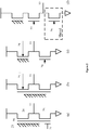
- a chemical sensing layer 23 is coupled to a floating gate 20 shared by two transistors (24 and 25) arranged as an inverter.
- An output 22 is connected to the drains.
- the voltage on the gate will have the effect of turning one transistor on and the other off such that the output is inherently digital.
- Further device approaches can be extended to 2(b) or 2(c) using bulk input modulation or 2(d) using pseudo CMOS logic.
- the oscillating signal may be provided by a signal generator in the semiconductor substrate capacitively coupled to the gate of a transistor.
- an oscillating signal from the signal generator could electrically bias the transistor to turn on and off for set periods, with any chemical signal adding to the bias to modulate those periods.
- the voltage of the oscillation will vary continually between Vss and Vdd.
- the signal may vary from 0V to 3.3V. Sawtooth, sinusoidal, or triangular waveforms are preferred.
- the frequency of the oscillating signal is dictated by factors such as the frequency scanning the array, the time interval of a chemical reaction being observed, and the resolution required for the digital output signal to detect a change in the ion concentration.
- the ISFET inverter can be driven by common or individual signal at a specific frequency, and the output signal phase will be modulated by the hydrogen or other target ion concentration.
- the output signal which essentially becomes a chemical modulated digital signal, dramatically simplifies the readout and processing blocks, and is immune to most electrical noise.
- the number of transducers and chambers will depend on the application but in preferred embodiments there will be an array of more than 10, more than 100, more than 1000, more than 10,000, more than 100, 000, or more than a 1,000,000. In applications requiring more transducers and the chamber size will typically be smaller.
- the chamber volume is less than 1mL, less than 10uL, less than 100nL, less than 30nL, less than 1nL, or less than 100pL.
- CDMA Code division multiple access
- CMOS based ISFETs are preferable and are described below to further explain the implementation.
- the oscillating signal may be connected to the bulk as shown in Figure 2(b).
- Figure 2(c) shows a third embodiment for a row of devices wherein the chemical sensing surface is coupled to a single FET and the second FET of the inverter is switched on and off by a row-select signal 26.
- the embodiment shown in Figure 2(d) is desirable.
- a single pixel comprises a sensing transistor, a pass transistor, and a selection transistor.
- the selection transistor can be used to control the final output 22 in a single row or column.
- Either of the row select control 26 or the column select control 27 can be connected to the oscillating signal. Since the output signal will be digital, the transistor size can be further scaled down to sub-micron, and limited by the chemical setup only. In any of these configurations, the signal loss and distortion is negligible since a digital output is used.
- transducer pixels can share one buffer and one front-end readout. However, in order to further speed up the processing, transducers in one row (or column) can share one readout channel. In each readout channel, the digital pulses are buffered using a digital inverter (or bit buffer).
- Figure 3 shows a counter system to readout the phase-modulated pulse signal and output a digital sequence.
- the output of a time to digital converter will be truncated to a short length representing the change of chemical signal.
- This configuration can reduce the data handled and memory required. For instance, the entire output, which might normally have 12-bits resolution, will be reduced to 4 bits and stored into memory.
- the base line will be treated as common signal and stored as well. Therefore for each pixel, the maximum data required is the base count times 4bits plus 10 bits common mode signal.
- nucleic acid such as DNA and RNA
- a nucleic acid such as DNA and RNA
- a probe up to or including a point on the nucleic acid to be identified.
- Nucleotides will become incorporated to the 3' end of the probe to extend the chain.
- This incorporation reaction has been shown to release hydrogen ions which are detectable by an ISFET with a suitably treated sensing surface.
- the surface may be Silicon Nitride, Silicon Dioxide, Tantalum Oxide, or others shown to have sensitivity to hydrogen ions.
- a nucleotide will only become incorporated if it is complementary to the nucleotide opposite.
- the known chemical compound added e.g. the type of nucleotide dATP, dNTP, dTTP, dGTP, or allele specific probe
- a change (or lack thereof) in output signal a nucleotide at a point of interest on the nucleic acid can be identified. Details of such application and implementation have been described in patent application US11/625844 and patents US7686929 and US788801 5 .
- nucleic acid As an extension to the identification of a single nucleotide base in a nucleic acid, it is desirable to identify a sequence of tens to hundreds of nucleotide bases.
- a whole chain of DNA is cut into small pieces, and copied to increase detection redundancy.
- the pieces are divided amongst an array of sensor pixels. Therefore every pixel data represents a copy of a small piece of DNA.
- Identifying the overlap of base sequences, in other words data similarity in memory, provides the entire DNA base sequence.
- This comparison can be implemented by digital logic, i.e. XOR, AND, NOR, NAND etc..
- a digital processing block can concatenate the sequence based on the comparison results. The processing can be performed in parallel with the sensing function, with the results of mapping fedback into the pre-process part, to reduce the computation complexity and memory requirement.
- a nucleic acid to be identified (TGACCC) is copied and cut up to provide four fragments (Fragment 1, 2, 3,4) with one fragment placed in one chamber, each chamber having one sensor (Sensor 1, 2, 3,4). There would normally be millions of identical copies of a given fragment in a chamber.
- a probe is attached to each fragment up to but not including the bases shown. The probe is not shown for simplicity of understanding.
- the order of nucleotides added is dATP, dCTP, dTTP, and dGTP (A, C, T, G), which is repeated until each fragment is fully extended.
- the fluid is initially set to pH7 and is reset to pH7 after every base is added.
- the oscillating input signal to the sensor is a triangular wave as shown in Figure 4(b) ,having a frequency higher than the rate of base addition, preferably higher than the rate of the smallest change to be detected.
- the amount of pH change can be extracted from this signal by removing the initial pulse width (i.e. at pH 7). This is converted to the number of bases that were extended by dividing the pH change by the rate of change per base (0.2pH/ base in our case). See the Sensor output in Figure 4(a) . In reality the pH change is not linear for each base extended nor is the change instantaneous and stable over the reaction.
- each fragment By correlating the addition of the known base with the count of extension, the sequence of each fragment can be identified.
- the pH change from an extension reaction may last 1 second.
- the pH is sampled 10 times over the 1 second period.
- the width of the ON periods will vary over the 4 second reaction window.
- the quantification of base extension may involve a complex algorithm looking at the minimum pulse width, average pulse width, sum of pulse widths, etc.
- Output is immune to conversion time and most electrical noise induced by the digital processing circuit.
- Transistor size can be reduced further since digital logic is adopted and transistor mismatch can be neglected.
- the processing and memory blocks can be integrated into a single chip.
- sequencing and comparison can be triggered accurately for all the pixels. Sequencing can be performed concurrently with the reaction, dramatically reducing the processing time and improving the processing accuracy.
- the reference signal is reset before each nucleotide insertion step to compensate for any background ion concentration (for example the concentration remaining from the previous insertion step).
- the reset reference signal together with the background chemical signal thus produces a consistent pre-insertion reference output signal, any subsequent modulation to the output signal representing the concentration change due to the current nucleotide insertion step.
- the device may be used to identify other chemicals. For example, a complex molecule having several identifiable elements of varying types can be identified be using a step-wise (or repeated) reaction with analyte specific reagents. The digital output will identify the exact type of the molecule.
- the chemical input to the system may be varied by a controlled chemical signal such that the initial ion concentration acts to modulate the output signal.
- the combined chemical signal can be swept through a range to examine the a) ion concentration within the buffer and b) examine the electrical operating point of the transistor (sub-threshold, linear, saturation).
- the former is useful when the initial ion concentration is within the buffer capacity such that any small changes will be masked by the buffer.
- the latter may be operated as described above with an inverter to create an output pulse whose width is modulated by the initial ion concentration.
- the two effects may be combined such that adding titrant moves the ion concentration operating point beyond the buffer capacity and also crosses a switching point of the inverter.
- the initial ion concentration can be measured by the time (amount of titrant added) until the slope reaches a threshold slope or the pH change exceeds a threshold. This is clearly an inverse relationship between time and concentration.
- the relationship may be determined by a model of the chemical system or determined empirically. The relationship may be stored as a look-up table in memory.
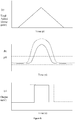
- the pH in graph 5(b) could be used to produce an analogue output signal from the ISFET to be detected and measured. It is also possible to form an ion sensitive switch as described above, where two FETs are arranged as an inverter biased to switch when the ion concentration exceeds a threshold (identified as the upper horizontal line in Figure 5(b) . The output will thus be ON or OFF, wherein the period ON depends on the initial ion concentration as shown in Figure 5(c) .
- the oscillation period in preferred embodiments is greater than 2 seconds, preferably greater than 5 seconds, 10 seconds, or 30 seconds. However, the period should not be so long as to miss changes in the ion concentration or slow down detection time. Thus in preferred embodiments, the oscillation period is less than 200 seconds, preferably less than 100 seconds, 60 seconds, or 50 seconds.
- a threshold may be reached when the concentration of titrated ions (T) plus initial ions (I) is greater than the buffer capacity (B).
- the initial ion concentration is determined at a first time using the steps discussed above and illustrated in Figure 5 .
- the steps are repeated at a second time to determine if more or less titrant was needed to reach the threshold.
- the threshold is reached at time 1 when: T 1 + I 1 > B ;
- titration may be unidirectional, such that titrant is added or removed in a first period, but the effect is not reversed in a second period.
- a threshold e.g. slope or change
- the titration electrode may be operated to add or release chemicals, which chemicals affect the ion concentration to be detected.
- the effect may be to increase or decrease ion concentration from the initial concentration.
- the titrant added need not be a predetermined amount, but may rather be added until one of the thresholds is reached. In this case the amount added is calculated.
- Titration may be achieved by exposing a titration electrode to the fluid.
- the electrode is connected to a controller which provides a controlled amount of electric current. Calculating the integral of current over time results in a known quantity of charge, which is proportional to the quantity of titrant released or adsorbed to the electrode.
- the titration electrode may be of the type described in B. van der Schoot et al., Titration-on-a-chip, chemical sensor-actuator systems from idea to commercial product, Sensors and Actuators B 105 (2005) 88-95 .
- the titration reaction at an electrode with a negative charge may by expressed as: 2H 2 0 + e - ⁇ H 2 (gas) + 2OH - which has the effect of raising pH.
- the titration reaction at an electrode with a positive charge may by expressed as: 2H 2 0 - e - ⁇ O 2 (gas) + 4H + which has the effect of lowering pH.
Landscapes
- Chemical & Material Sciences (AREA)
- Life Sciences & Earth Sciences (AREA)
- Health & Medical Sciences (AREA)
- Organic Chemistry (AREA)
- Engineering & Computer Science (AREA)
- Proteomics, Peptides & Aminoacids (AREA)
- Physics & Mathematics (AREA)
- Molecular Biology (AREA)
- Analytical Chemistry (AREA)
- Wood Science & Technology (AREA)
- Zoology (AREA)
- Immunology (AREA)
- Biochemistry (AREA)
- General Health & Medical Sciences (AREA)
- Biophysics (AREA)
- Microbiology (AREA)
- Bioinformatics & Cheminformatics (AREA)
- Genetics & Genomics (AREA)
- General Engineering & Computer Science (AREA)
- Biotechnology (AREA)
- Chemical Kinetics & Catalysis (AREA)
- Pathology (AREA)
- General Physics & Mathematics (AREA)
- Electrochemistry (AREA)
- Spectroscopy & Molecular Physics (AREA)
- Microelectronics & Electronic Packaging (AREA)
- Biomedical Technology (AREA)
- Urology & Nephrology (AREA)
- Hematology (AREA)
- Food Science & Technology (AREA)
- Medicinal Chemistry (AREA)
- Apparatus Associated With Microorganisms And Enzymes (AREA)
- Measuring Or Testing Involving Enzymes Or Micro-Organisms (AREA)
- Investigating Or Analyzing Materials By The Use Of Electric Means (AREA)
Description
- The present invention relates to devices for chemical sensing. In particular the invention may be used to provide a digital output signal dependent on the concentration of an ion in a fluid. The invention is applicable to nucleic acid identification and sequencing.
- Previously publications have disclosed the ability of an ION Sensitive Field Effect Transistor (ISFET) to detect chemicals proximate the sensing surface. This may be used to determine the presence of a target analyte by detection of products of a chemical reaction. In one example, ISFETs can be used determine the identity of one or more portions of a nucleic acid template by detecting the change in pH resulting from nucleotide insertion at the end of a nucleic acid. Typically hydrogen ions (protons) are released during the reaction. The electrical signal strength of the ISFET depends on the amount of hydrogen ions released, which is expressed as an analogue output signal, which is either a voltage or current signal.
- For large scale arrays of ISFETs, such as might be used in DNA sequencing, the inventors have appreciated that processing this analogue data requires enormous computing power and a bandwidth of gigabits/second.
- In addition, the normal method requires accurate analogue readout circuitry, and is sensitive to the parasitic components, and environmental electrical noise. High accuracy and large-scale analogue systems limit the processing speed and integration ability; thereby constraining the detection efficiency and scalability. Moreover, high performance front-end interface circuitry consumes large amounts of system area and power, make on-chip data processing unrealistic.
- The inventors propose herein a novel semiconductor and method that addresses one or more of the above deficiencies.
- According to a first aspect of the invention there is provided a chemical sensing device for measuring an ion concentration of a fluid, the device comprising a transducer having a first output signal and arranged to receive an electrical input. The transducer switches the first output signal between an ON and OFF state in dependence upon the electrical input signal and a chemical input signal. The device comprises a chemical sensing surface coupled to the transducer arranged to receive a chemical input signal. A signal generator oscillates the chemical input signal to vary the switching point of the transducer and switch the first electrical output signal ON for a first period and OFF for a second period wherein the ion concentration of the fluid modulates a pulse width of the first and/or second period.
- The signal generator may comprise a titration electrode arranged to release or adsorb a chemical, which chemical affects a concentration of ions detected by the chemical sensing surface. The signal generator may further comprise a controller to provide an oscillating electrical current to the titration electrode.
- The transducer may comprise a first transistor of a first type connected to a second transistor of a second type to form a CMOS inverter. The chemical sensitive surface may be coupled to gates of the first and second transistors. The gate may be a floating gate.
- The first electrical output signal may be provided to one or more further transistors to form a logic circuit.
- The chemical sensing device may further comprise a demodulator receiving the first electrical output signal, the demodulator providing a second digital output signal representing the magnitude of the chemical input signal.
- The demodulator may be one of: a Phase Demodulator or Time to Digital Convertor (TDC).
- The chemical sensing device may further comprise an encoder connected to the second output signal, the encoder arranged to provide a third output signal comprising a 2-bit binary code.
- Preferably, the signal generator provides an oscillating waveform that is one of: a sawtooth wave, a sinusoidal wave, or a triangular wave.
- According to a second aspect of the invention there is provided a method of determining one or more components of an analyte in a fluid using an chemical sensing device according the first aspect, and comprising the steps of (i) providing the fluid to a chemical transducer; (ii) oscillating a chemical input signal to the transducer to switch a first electrical output signal between an ON and OFF state, wherein an ion concentration of the fluid modulates a pulse width of the ON or OFF state of the first output signal; (iii) combining an analyte specific reagent with the fluid, whereby ions are produced if the reagent reacts with the analyte in the fluid; (iv) oscillating one or more chemical input signals to the transducer to switch a second electrical output signal between an ON and OFF state, wherein the ion concentration of the fluid modulates a pulse width of the ON or OFF state of the second output signal; (v) comparing the first and second output signals to quantify a change in ion concentration of the fluid; and (vi) comparing the change in ion concentration with a threshold to determine whether the reagent reacted with the analyte to determine a component of the analyte.
- The method may further comprise demodulating the first and second modulated output signals to provide first and second digital output signals representing an ion concentration and then comparing the first and second digital output signals to quantify a change in ion concentration of the fluid.
- The method may also further comprise removing the extant reagent from the fluid after (iv). Indeed, it is also preferred that at least (ii) to (vi) are repeated to determine further components of the analyte.
- The analyte is preferably a nucleic acid template to be sequenced and the reagent is a known type of nucleotide. It is preferred, therefore, that the ion concentration changes depending on whether the nucleotide is inserted onto the nucleic acid template.
- The change in ion concentration ideally correlate to the number of nucleotide bases inserted onto the nucleic acid template.
- The encoder may provide a 2-bit binary code representing the type of nucleotide inserted.
- Thus, in a further aspect, there is provided an array of chemical sensing devices discussed above. The array may comprise a multiplexer connected to each device to select which first output signal is to be demodulated. Preferably, the array is of chemical sensing devices wherein said transducer comprises a first transistor of a first type connected to a second transistor of a second type to form a CMOS inverter. Preferably, said array comprises a multiplexer connected to each said second transistor to activate or deactivate individual devices. The array may further comprise a CDMA processor to encode output signal from each device, preferably enabling said output signals to be transmitted on a single channel.
- Specific embodiments of the invention will now be described by way of example only with reference to the accompanying figures, in which:
-
Figure 1 is a block diagram of a system of a preferred embodiment; -
Figure 2 shows four schematic arrangements of transducers; -
Figure 3 is a schematic of a readout circuit; -
Figure 4 shows graphs of output signals of nucleic acid reactions; and -
Figure 5 . shows graphs of input and output signals for a system having an oscillating chemical input. - In a system comprising the invention there will typically be a semiconductor substrate housing the sensor and signal processing, overlaid by a substrate containing fluidic channels and one or more chambers. The chambers contain a fluid which has an ion concentration to be measured. The ion concentration may be constant or may be changing. The change may be a result of a chemical reaction releasing or absorbing the ions. The limit of detection of such a system is governed by a) the amount of buffer in the fluid which masks changes in ion concentration and b) the electrical characteristics of the transistor which requires the ionic charges to create an electric field to permit electric current to flow and be detected. These can be seen as thresholds to be exceeded. In the present invention a controlled oscillating signal is provided to the system, which in combination with the chemical/ionic signal exceeds one or both of these thresholds to provide a detectable output signal. The effect of the controlled signal is subtracted from the output signal to determine the effect of the chemical signal contribution. By oscillating the controlled signal the net effect over time to the system is zero. The oscillating signal is ideally continuously varying over a portion of the period such that the point at which the threshold is crossed can be determined.
- In one embodiment, the oscillating signal is a chemical signal provided to the fluid to change the ion concentration within the buffer. In another embodiment, the oscillating signal is an electrical signal provided to the sensor transducer to change the electrical operating point. Combinations of these embodiments are envisaged and within the scope of the invention.
- In such a system the chemical signal can be regarded as modulating the output signal and doing so in an efficient form for data processing. Ideally the chemical concentration is converted to a digital signal to be further processed. Processing of this signal may be performed in hardware or software.
- A block diagram of an exemplary system is shown in
Figure 1 . A fluid sample, which contains a concentration of an analyte (including zero concentration where the analyte is absent from the sample), is in contact with a chemical sensing surface of an ISFET that converts the concentration of the analyte into an analogue electrical signal. A transducer converts the chemical signal into an analogue signal. The transducer is connected to an oscillating signal input. The chemical signal and oscillating signal combine to produce an oscillating output signal. If the transducer comprises an ISFET forming part of a CMOS inverter, the transducer will turn on and off to produce a pulsed output signal as shown. The analogue chemical signal contributes to modulate the output signal such that the phase shifts or pulse width changes. This change represents the chemical concentration. Then a Time to Digital Converter or Phase Demodulator decodes the pulse signal and outputs a digital signal. The contribution from the oscillating input signal can be deducted to leave the net chemical contribution. These signals may be pre-processed and stored in memory. The Time to Digital Converter may be of the types described in: - Jianjun Yu et al, 12-Bit Vernier Ring Time-to-Digital Converter in 0.13 um CMOS Technology, IEEE JOURNAL OF SOLID-STATE CIRCUITS, VOL. 45, NO. 4, April 2010; or
- Gordon W. Roberts, A Brief Introduction to Time-to-Digital Digital-to-Time Converters, IEEE TRANSACTIONS ON CIRCUITS AND SYSTEMS II: EXPRESS BRIEFS, VOL. 57, NO. 3, March 2010.
- As discussed further below the signals may represent a series of nucleotide incorporation reaction of a fragmented DNA strand, in which case the signals are further processed to sequence the complete DNA by mapping algorithm units.
- In one embodiment, depicted in
Figure 2a , achemical sensing layer 23 is coupled to a floatinggate 20 shared by two transistors (24 and 25) arranged as an inverter. Anoutput 22 is connected to the drains. The voltage on the gate will have the effect of turning one transistor on and the other off such that the output is inherently digital. For further reference on this arrangement and operation see application PCT/IB2011/002376. Further device approaches can be extended to 2(b) or 2(c) using bulk input modulation or 2(d) using pseudo CMOS logic. - By connecting a signal generator to a terminal of a transistor, the transistor can be biased such that the output is of a predetermined form to enable a chemical signal to modulate the output as desired. The oscillating signal may be provided by a signal generator in the semiconductor substrate capacitively coupled to the gate of a transistor. For example an oscillating signal from the signal generator could electrically bias the transistor to turn on and off for set periods, with any chemical signal adding to the bias to modulate those periods. Typically the voltage of the oscillation will vary continually between Vss and Vdd. For example the signal may vary from 0V to 3.3V. Sawtooth, sinusoidal, or triangular waveforms are preferred. The frequency of the oscillating signal is dictated by factors such as the frequency scanning the array, the time interval of a chemical reaction being observed, and the resolution required for the digital output signal to detect a change in the ion concentration.
- The ISFET inverter can be driven by common or individual signal at a specific frequency, and the output signal phase will be modulated by the hydrogen or other target ion concentration. The output signal, which essentially becomes a chemical modulated digital signal, dramatically simplifies the readout and processing blocks, and is immune to most electrical noise.
- The number of transducers and chambers will depend on the application but in preferred embodiments there will be an array of more than 10, more than 100, more than 1000, more than 10,000, more than 100, 000, or more than a 1,000,000. In applications requiring more transducers and the chamber size will typically be smaller. In preferred embodiments, the chamber volume is less than 1mL, less than 10uL, less than 100nL, less than 30nL, less than 1nL, or less than 100pL.
- A Code division multiple access (CDMA) technique may also be incorporated in the system to encode the data from each transducer pixel in an array of transducers, allowing all the pixel data to be sent down a single channel.
- Due to its simplified readout system, methods and devices of the invention can be widely implemented in different technologies, such as a discrete glass ISFET or a CMOS based ISFET. For large scale integration purposes, CMOS based ISFETs are preferable and are described below to further explain the implementation.
- In contrast to the embodiment of
Figure 2(a) , the oscillating signal may be connected to the bulk as shown inFigure 2(b). Figure 2(c) shows a third embodiment for a row of devices wherein the chemical sensing surface is coupled to a single FET and the second FET of the inverter is switched on and off by a row-select signal 26. For a two-dimensional array of transducers, the embodiment shown inFigure 2(d) is desirable. - In
Figure 2(d) a single pixel comprises a sensing transistor, a pass transistor, and a selection transistor. The selection transistor can be used to control thefinal output 22 in a single row or column. Either of the rowselect control 26 or the columnselect control 27 can be connected to the oscillating signal. Since the output signal will be digital, the transistor size can be further scaled down to sub-micron, and limited by the chemical setup only. In any of these configurations, the signal loss and distortion is negligible since a digital output is used. - All the transducer pixels can share one buffer and one front-end readout. However, in order to further speed up the processing, transducers in one row (or column) can share one readout channel. In each readout channel, the digital pulses are buffered using a digital inverter (or bit buffer).
Figure 3 shows a counter system to readout the phase-modulated pulse signal and output a digital sequence. - The output of a time to digital converter will be truncated to a short length representing the change of chemical signal. This configuration can reduce the data handled and memory required. For instance, the entire output, which might normally have 12-bits resolution, will be reduced to 4 bits and stored into memory. The base line will be treated as common signal and stored as well. Therefore for each pixel, the maximum data required is the base count times 4bits plus 10 bits common mode signal.
- In the field of genetic testing, it is desirable to identify one or more nucleotides of a nucleic acid (such as DNA and RNA). Typically a single strand of nucleic acid is annealed with a probe up to or including a point on the nucleic acid to be identified. Nucleotides will become incorporated to the 3' end of the probe to extend the chain. This incorporation reaction has been shown to release hydrogen ions which are detectable by an ISFET with a suitably treated sensing surface. For example the surface may be Silicon Nitride, Silicon Dioxide, Tantalum Oxide, or others shown to have sensitivity to hydrogen ions.
- A nucleotide will only become incorporated if it is complementary to the nucleotide opposite. By correlating the known chemical compound added (e.g. the type of nucleotide dATP, dNTP, dTTP, dGTP, or allele specific probe) to a change (or lack thereof) in output signal, a nucleotide at a point of interest on the nucleic acid can be identified. Details of such application and implementation have been described in
patent application US11/625844 patents US7686929 andUS788801 5 . - As an extension to the identification of a single nucleotide base in a nucleic acid, it is desirable to identify a sequence of tens to hundreds of nucleotide bases.
- In one method known as the shooting gun method, a whole chain of DNA is cut into small pieces, and copied to increase detection redundancy. The pieces are divided amongst an array of sensor pixels. Therefore every pixel data represents a copy of a small piece of DNA. Identifying the overlap of base sequences, in other words data similarity in memory, provides the entire DNA base sequence. This comparison can be implemented by digital logic, i.e. XOR, AND, NOR, NAND etc.. A digital processing block can concatenate the sequence based on the comparison results. The processing can be performed in parallel with the sensing function, with the results of mapping fedback into the pre-process part, to reduce the computation complexity and memory requirement.
- Simulation results based on a 6-base long DNA is shown in
Figure 4 , wherein the graphs show (a) the base calling order and base extension at each of four sensors over the entire reaction period (16seconds) and (b) the oscillating reference signal and modulated output signals for each sensor over a single reaction (2 seconds). - An exemplary simulation of a method of sequencing is described below and shown in
Figure 4 . The set up parameters and outputs are given in the table below showing the simplified results of the processing. A nucleic acid to be identified (TGACCC) is copied and cut up to provide four fragments (Fragment Sensor - The order of nucleotides added (the bases call order) is dATP, dCTP, dTTP, and dGTP (A, C, T, G), which is repeated until each fragment is fully extended. The fluid is initially set to pH7 and is reset to pH7 after every base is added.
- Every 2 seconds in this case, a new base will be added to each chamber in the order given above. Extension will occur if the added base is complementary to the fragment at the base opposite to release hydrogen ions. For each base extension, the released hydrogen will induce a specific pH drop, in our case, - 0.2 pH per base extended. This pH will be directly reflected by the output signal with a modulated width or phase correlating to the pH change (
Figure 4(b) ). Note that in the case where an inverter is used, more base extension, leading to greater ion release, reduces the ON period of the output signal. - The oscillating input signal to the sensor is a triangular wave as shown in
Figure 4(b) ,having a frequency higher than the rate of base addition, preferably higher than the rate of the smallest change to be detected. - The amount of pH change can be extracted from this signal by removing the initial pulse width (i.e. at pH 7). This is converted to the number of bases that were extended by dividing the pH change by the rate of change per base (0.2pH/ base in our case). See the Sensor output in
Figure 4(a) . In reality the pH change is not linear for each base extended nor is the change instantaneous and stable over the reaction. - By correlating the addition of the known base with the count of extension, the sequence of each fragment can be identified. The base of each fragment can be represented by a 2-bit binary code provided by an encoder (e.g. 00=A, 01 =T, 10=G, 11=C). Finally the identified fragments are reassembled using known mapping techniques (not shown):
Nucleic Acid Template T G A C C C BASE Call Order A C T G Repeat... Fragment 1 T G A C Fragment 2 G A C C Fragment 3 A C C C Fragment 4 G A C C Extension Count Sensor1 0 1 1 0 1 0 0 1 Sensor2 0 0 1 0 1 0 0 2 Sensor3 1 0 0 3 0 0 0 0 Sensor4 0 0 1 0 1 0 0 2 - For example, during a 4 second period of base addition, the pH change from an extension reaction may last 1 second. To measure the change, capturing the peak and width of the pH change, the pH is sampled 10 times over the 1 second period. The width of the ON periods will vary over the 4 second reaction window. The quantification of base extension may involve a complex algorithm looking at the minimum pulse width, average pulse width, sum of pulse widths, etc.
- It can be seen that the output sequence can be easily derived from this scheme.
- Advantageous of preferred embodiments of a system are:
- by using a novel configuration of ISFETs, the total transistor count for a single detection pixel can be reduced to two (including selection transistor).
- no analogue processing circuitry is necessary.
- Output is immune to conversion time and most electrical noise induced by the digital processing circuit.
- Transistor size can be reduced further since digital logic is adopted and transistor mismatch can be neglected.
- The processing and memory blocks can be integrated into a single chip.
- Since all detection is synchronized, sequencing and comparison can be triggered accurately for all the pixels. Sequencing can be performed concurrently with the reaction, dramatically reducing the processing time and improving the processing accuracy.
- In one embodiment, the reference signal is reset before each nucleotide insertion step to compensate for any background ion concentration (for example the concentration remaining from the previous insertion step). The reset reference signal together with the background chemical signal thus produces a consistent pre-insertion reference output signal, any subsequent modulation to the output signal representing the concentration change due to the current nucleotide insertion step. In addition to sequencing a nucleic acid, the device may be used to identify other chemicals. For example, a complex molecule having several identifiable elements of varying types can be identified be using a step-wise (or repeated) reaction with analyte specific reagents. The digital output will identify the exact type of the molecule.
- As discussed above, in one embodiment the chemical input to the system may be varied by a controlled chemical signal such that the initial ion concentration acts to modulate the output signal. The combined chemical signal can be swept through a range to examine the a) ion concentration within the buffer and b) examine the electrical operating point of the transistor (sub-threshold, linear, saturation). The former is useful when the initial ion concentration is within the buffer capacity such that any small changes will be masked by the buffer. The latter may be operated as described above with an inverter to create an output pulse whose width is modulated by the initial ion concentration. The two effects may be combined such that adding titrant moves the ion concentration operating point beyond the buffer capacity and also crosses a switching point of the inverter.
- The effect is demonstrated in
Figure 5 . In graph 5(a) a controlled quantity of titrant is added to the fluid over a first period and the removed over a second period. The net chemical effect on the system is thus zero. In graph 5(b) the pH of two cases are plotted over the same periods. In the first case (solid line), the hydrogen ion concentration is small compared to the buffer capacity and so takes a long time before there is a detectable pH change. In the second case (dashed line), the hydrogen ion concentration is large compared to the buffer capacity and so takes less time before there is a detectable pH change. As the ion concentration exceeds the buffer capacity the rate of pH change per quantity of titrant added increases. This is seen as a steeper slope after the horizontal buffer lines. - The initial ion concentration can be measured by the time (amount of titrant added) until the slope reaches a threshold slope or the pH change exceeds a threshold. This is clearly an inverse relationship between time and concentration. The relationship may be determined by a model of the chemical system or determined empirically. The relationship may be stored as a look-up table in memory.
- The pH in graph 5(b) could be used to produce an analogue output signal from the ISFET to be detected and measured. It is also possible to form an ion sensitive switch as described above, where two FETs are arranged as an inverter biased to switch when the ion concentration exceeds a threshold (identified as the upper horizontal line in
Figure 5(b) . The output will thus be ON or OFF, wherein the period ON depends on the initial ion concentration as shown inFigure 5(c) . - The titration reaction is naturally slow and so the oscillation period in preferred embodiments is greater than 2 seconds, preferably greater than 5 seconds, 10 seconds, or 30 seconds. However, the period should not be so long as to miss changes in the ion concentration or slow down detection time. Thus in preferred embodiments, the oscillation period is less than 200 seconds, preferably less than 100 seconds, 60 seconds, or 50 seconds.
- A threshold may be reached when the concentration of titrated ions (T) plus initial ions (I) is greater than the buffer capacity (B).
- In cases where a change in ion concentration is to be detected, the initial ion concentration is determined at a first time using the steps discussed above and illustrated in
Figure 5 . The steps are repeated at a second time to determine if more or less titrant was needed to reach the threshold. - The threshold is reached at
time 1 when:
- The threshold is reached at
time 2 when:

- Thus the change in initial ion concentration is known from the amount of titration required at each time to reach the threshold.
- In cases where the initial ion concentration is to be measured only once, titration may be unidirectional, such that titrant is added or removed in a first period, but the effect is not reversed in a second period. To measure the absolute initial ion concentration, it is necessary to know the buffer capacity of the fluid and the amount of titrant added to exceed the capacity to reach a threshold (e.g. slope or change):

- In either case, the titration electrode may be operated to add or release chemicals, which chemicals affect the ion concentration to be detected. The effect may be to increase or decrease ion concentration from the initial concentration.
- The titrant added need not be a predetermined amount, but may rather be added until one of the thresholds is reached. In this case the amount added is calculated.
- Titration may be achieved by exposing a titration electrode to the fluid. The electrode is connected to a controller which provides a controlled amount of electric current. Calculating the integral of current over time results in a known quantity of charge, which is proportional to the quantity of titrant released or adsorbed to the electrode. The titration electrode may be of the type described in B. van der Schoot et al., Titration-on-a-chip, chemical sensor-actuator systems from idea to commercial product, Sensors and Actuators B 105 (2005) 88-95.
- The titration reaction at an electrode with a negative charge may by expressed as:
2H 20 + e- → H2 (gas) + 2OH-
which has the effect of raising pH. - The titration reaction at an electrode with a positive charge may by expressed as:
2H20 - e- → O2 (gas) + 4H+
which has the effect of lowering pH. - Although the invention has been described in terms of preferred embodiments as set forth above, it should be understood that these embodiments are illustrative only and that the claims are not limited to those embodiments. Those skilled in the art will be able to make modifications and alternatives in view of the disclosure which are contemplated as falling within the scope of the appended claims. For example, references to connections may be made directly or indirectly, as appropriate. Each feature disclosed or illustrated in the present specification may be incorporated in the invention, whether alone or in any appropriate combination with any other feature disclosed or illustrated herein.
Claims (12)
- A chemical sensing device for measuring an ion concentration of a fluid, the device comprising:- a transducer for providing a first electrical output signal and arranged to receive an electrical input signal, the transducer switching the first electrical output signal between an ON and OFF state in dependence upon the electrical input signal and a chemical input signal;- a chemical sensing surface coupled to the transducer for receiving the chemical input signal; and- a signal generator for oscillating the chemical input signal to vary the switching point of the transducer and switch the first electrical output signal ON for a first period and OFF for a second period, wherein the ion concentration of the fluid modulates a pulse width of the first and/or second period.
- A chemical sensing device according to claim 1, wherein the signal generator comprises a titration electrode arranged to release or adsorb a chemical.
- A chemical sensing device according to claim 2, wherein the signal generator further comprises a controller to provide an oscillating electrical current to the titration electrode.
- A chemical sensing device according to any preceding claim, wherein said transducer comprises a first transistor of a first type connected to a second transistor of a second type to form a CMOS inverter.
- A chemical sensing device according to any preceding claim, further comprising a demodulator receiving the first electrical output signal, the demodulator providing a second digital output signal representing the magnitude of the chemical input signal.
- A chemical sensing device according to claim 5, further comprising an encoder connected to the second output signal, the encoder arranged to provide a third output signal comprising a 2-bit binary code.
- An array of apparatuses according to any preceding claim, preferably comprising a multiplexer connected to each device to select which first output signal is to be demodulated.
- A method of determining one or more components of an analyte in a fluid, and comprising:(i) providing the fluid to a chemical transducer;(ii) oscillating a chemical input signal to the transducer to switch a first electrical output signal between an ON and OFF state, wherein an ion concentration of the fluid modulates a pulse width of the ON or OFF state of the first output signal;(iii) combining an analyte specific reagent with the fluid, whereby ions are produced if the reagent reacts with the analyte in the fluid;(iv) oscillating one or more chemical input signals to the transducer switch a second electrical output signal between an ON and OFF state, wherein the ion concentration of the fluid modulates a pulse width of the ON or OFF state of the second output signal;(v) comparing the first and second output signals to quantify a change in ion concentration of the fluid; and(vi) comparing the change in ion concentration with a threshold to determine whether the reagent reacted with the analyte to determine a component of the analyte.
- A method according to claim 8 further comprising demodulating the first and second modulated output signals to provide first and second digital output signals representing an ion concentration and then comparing the first and second digital output signals to quantify a change in ion concentration of the fluid.
- A method according to claim 8 or 9, further comprising removing the extant reagent from the fluid after (iv).
- A method according to claim 8, 9 or 10, further comprising repeating (ii) to (vi) to determine further components of the analyte.
- A method according to anyone of claims 8 to 11, wherein the analyte is a nucleic acid template to be sequenced and the reagent is a known type of nucleotide, and wherein the ion concentration changes depending on whether the nucleotide is inserted onto the nucleic acid template.
Priority Applications (1)
| Application Number | Priority Date | Filing Date | Title |
|---|---|---|---|
| EP17183237.1A EP3258257A1 (en) | 2010-10-28 | 2011-10-28 | Chemical sensing device |
Applications Claiming Priority (2)
| Application Number | Priority Date | Filing Date | Title |
|---|---|---|---|
| GBGB1018224.4A GB201018224D0 (en) | 2010-10-28 | 2010-10-28 | Chemical sensing device |
| PCT/GB2011/052105 WO2012056247A1 (en) | 2010-10-28 | 2011-10-28 | Chemical sensing device |
Related Child Applications (2)
| Application Number | Title | Priority Date | Filing Date |
|---|---|---|---|
| EP17183237.1A Division-Into EP3258257A1 (en) | 2010-10-28 | 2011-10-28 | Chemical sensing device |
| EP17183237.1A Division EP3258257A1 (en) | 2010-10-28 | 2011-10-28 | Chemical sensing device |
Publications (2)
| Publication Number | Publication Date |
|---|---|
| EP2633296A1 EP2633296A1 (en) | 2013-09-04 |
| EP2633296B1 true EP2633296B1 (en) | 2017-10-11 |
Family
ID=43401454
Family Applications (2)
| Application Number | Title | Priority Date | Filing Date |
|---|---|---|---|
| EP17183237.1A Withdrawn EP3258257A1 (en) | 2010-10-28 | 2011-10-28 | Chemical sensing device |
| EP11782200.7A Active EP2633296B1 (en) | 2010-10-28 | 2011-10-28 | Chemical sensing device and measuring method |
Family Applications Before (1)
| Application Number | Title | Priority Date | Filing Date |
|---|---|---|---|
| EP17183237.1A Withdrawn EP3258257A1 (en) | 2010-10-28 | 2011-10-28 | Chemical sensing device |
Country Status (8)
| Country | Link |
|---|---|
| US (3) | US9683260B2 (en) |
| EP (2) | EP3258257A1 (en) |
| JP (2) | JP5982385B2 (en) |
| CN (1) | CN103189741B (en) |
| CA (1) | CA2811701C (en) |
| ES (1) | ES2649064T3 (en) |
| GB (2) | GB201018224D0 (en) |
| WO (1) | WO2012056247A1 (en) |
Families Citing this family (6)
| Publication number | Priority date | Publication date | Assignee | Title |
|---|---|---|---|---|
| US9702846B2 (en) | 2013-11-08 | 2017-07-11 | Taiwan Semiconductor Manufacturing Company, Ltd. | Biosensor device and related method |
| JP6239665B2 (en) * | 2016-03-16 | 2017-11-29 | 株式会社東芝 | Semiconductor device |
| JP7231963B2 (en) * | 2017-02-21 | 2023-03-02 | 国立大学法人山形大学 | Electrochemical measuring device |
| CN110208676A (en) * | 2019-05-20 | 2019-09-06 | 西北工业大学 | Front end reads the equivalent noise charge test circuit and test method of integrated circuit |
| CN112880401A (en) * | 2019-11-29 | 2021-06-01 | 科德尔科股份公司 | System for measuring the percentage of copper in white metal in a smelting furnace |
| US11614421B2 (en) | 2020-05-08 | 2023-03-28 | Taiwan Semiconductor Manufacturing Company Ltd. | BioFET system |
Family Cites Families (32)
| Publication number | Priority date | Publication date | Assignee | Title |
|---|---|---|---|---|
| US4478914B1 (en) * | 1980-01-24 | 1997-06-17 | Roger W Giese | Process for applying multiple layers of a protein and a ligand extender to a surface and to the multiple layer system |
| US4488556A (en) * | 1982-06-03 | 1984-12-18 | Critikon, Inc. | AC Mode operation of chemfet devices |
| JPS60230038A (en) * | 1984-04-27 | 1985-11-15 | Hochiki Corp | Photodetecting circuit of photoelectric analog smoke detector |
| US4735906A (en) * | 1984-11-28 | 1988-04-05 | Texas A&M University | Sensor having piezoelectric crystal for microgravimetric immunoassays |
| US4716448A (en) * | 1985-09-03 | 1987-12-29 | Kelly Kevin A | CHEMFET operation without a reference electrode |
| GB8522207D0 (en) * | 1985-09-06 | 1985-10-09 | Kodak Ltd | Ion-sensitive electrochemical sensor |
| GB8528794D0 (en) * | 1985-11-22 | 1985-12-24 | Emi Plc Thorn | Buffer compensation in enzyme |
| GB2200999B (en) * | 1987-02-06 | 1990-05-09 | Emi Plc Thorn | Surface impedance measurement devices |
| US4847193A (en) * | 1987-06-18 | 1989-07-11 | Gene-Trak Systems | Signal amplification in an assay employing a piezoelectric oscillator |
| FR2620868B1 (en) * | 1987-09-22 | 1994-03-25 | Thomson Csf | PROCESS FOR PRODUCING MICROCAVITES AND APPLICATION TO AN ELECTROCHEMICAL SENSOR AS WELL AS A GAS PHASE CHOMATOGRAPHER |
| US4874499A (en) * | 1988-05-23 | 1989-10-17 | Massachusetts Institute Of Technology | Electrochemical microsensors and method of making such sensors |
| US6235488B1 (en) * | 1988-09-29 | 2001-05-22 | Agilent Technologies, Inc. | Surface preparation for chemical-specific binding |
| AT393416B (en) * | 1989-04-27 | 1991-10-25 | Avl Verbrennungskraft Messtech | MEASURING METHOD FOR DETERMINATION OR MONITORING OF MECHANICAL AND / OR PHYSICAL SIZES |
| CA2121797A1 (en) * | 1991-10-21 | 1993-04-29 | James W. Holm-Kennedy | Method and device for biochemical sensing |
| JPH06249825A (en) * | 1993-02-26 | 1994-09-09 | Tokyo Gas Co Ltd | FET sensor |
| JPH0735718A (en) * | 1993-07-21 | 1995-02-07 | Nippon Soken Inc | Alcohol concentration sensor |
| US5494831A (en) * | 1993-08-30 | 1996-02-27 | Hughes Aircraft Company | Electrochemical immunosensor system and methods |
| US5827482A (en) * | 1996-08-20 | 1998-10-27 | Motorola Corporation | Transistor-based apparatus and method for molecular detection and field enhancement |
| JP3567082B2 (en) * | 1998-05-28 | 2004-09-15 | 日本特殊陶業株式会社 | Pump current stabilization method for gas sensor |
| GB0105831D0 (en) | 2001-03-09 | 2001-04-25 | Toumaz Technology Ltd | Method for dna sequencing utilising enzyme linked field effect transistors |
| US8114591B2 (en) | 2001-03-09 | 2012-02-14 | Dna Electronics Ltd. | Sensing apparatus and method |
| WO2003021247A1 (en) * | 2001-08-28 | 2003-03-13 | Duke University | Biosensor |
| US7462512B2 (en) * | 2004-01-12 | 2008-12-09 | Polytechnic University | Floating gate field effect transistors for chemical and/or biological sensing |
| US7544979B2 (en) * | 2004-04-16 | 2009-06-09 | Technion Research & Development Foundation Ltd. | Ion concentration transistor and dual-mode sensors |
| GB2416210B (en) * | 2004-07-13 | 2008-02-20 | Christofer Toumazou | Ion sensitive field effect transistors |
| WO2008107014A1 (en) * | 2007-03-02 | 2008-09-12 | Dna Electronics Ltd | Qpcr using solid-state ph sensing |
| WO2009103034A2 (en) * | 2008-02-13 | 2009-08-20 | Board Of Regents, The University Of Texas System | System, method and apparatus for an amorphous iridium oxide film ph sensor |
| JP4927785B2 (en) * | 2008-06-02 | 2012-05-09 | 日本電信電話株式会社 | Field effect sensor |
| GB2461128B (en) * | 2008-06-25 | 2010-12-15 | Ion Torrent Systems Inc | ChemFET Arrays for Nucleic Acid Sequencing |
| US20100137143A1 (en) * | 2008-10-22 | 2010-06-03 | Ion Torrent Systems Incorporated | Methods and apparatus for measuring analytes |
| CA2765314A1 (en) * | 2009-06-10 | 2010-12-16 | Helmholtz Zentrum Muenchen Deutsches Forschungszentrum Fuer Gesundheit U Nd Umwelt (Gmbh) | Semiconductor biosensors |
| TWI400888B (en) | 2010-04-13 | 2013-07-01 | Univ Nat Chi Nan | Ion sensing circuit |
-
2010
- 2010-10-28 GB GBGB1018224.4A patent/GB201018224D0/en not_active Ceased
-
2011
- 2011-10-28 JP JP2013535511A patent/JP5982385B2/en active Active
- 2011-10-28 WO PCT/GB2011/052105 patent/WO2012056247A1/en not_active Ceased
- 2011-10-28 CA CA2811701A patent/CA2811701C/en active Active
- 2011-10-28 EP EP17183237.1A patent/EP3258257A1/en not_active Withdrawn
- 2011-10-28 US US13/881,986 patent/US9683260B2/en active Active
- 2011-10-28 ES ES11782200.7T patent/ES2649064T3/en active Active
- 2011-10-28 CN CN201180052589.4A patent/CN103189741B/en active Active
- 2011-10-28 EP EP11782200.7A patent/EP2633296B1/en active Active
- 2011-10-28 GB GB1118666.5A patent/GB2485068B/en active Active
-
2016
- 2016-07-20 JP JP2016142766A patent/JP6449198B2/en active Active
-
2017
- 2017-05-15 US US15/594,994 patent/US10144964B2/en active Active
-
2018
- 2018-10-02 US US16/149,474 patent/US10697011B2/en active Active
Non-Patent Citations (1)
| Title |
|---|
| None * |
Also Published As
| Publication number | Publication date |
|---|---|
| CN103189741B (en) | 2016-09-07 |
| US9683260B2 (en) | 2017-06-20 |
| US10697011B2 (en) | 2020-06-30 |
| CA2811701C (en) | 2014-07-22 |
| WO2012056247A1 (en) | 2012-05-03 |
| CA2811701A1 (en) | 2012-05-03 |
| GB2485068A (en) | 2012-05-02 |
| US20130252828A1 (en) | 2013-09-26 |
| CN103189741A (en) | 2013-07-03 |
| EP2633296A1 (en) | 2013-09-04 |
| JP2014508915A (en) | 2014-04-10 |
| EP3258257A1 (en) | 2017-12-20 |
| US20190040463A1 (en) | 2019-02-07 |
| US10144964B2 (en) | 2018-12-04 |
| JP5982385B2 (en) | 2016-08-31 |
| GB201118666D0 (en) | 2011-12-14 |
| JP2017006132A (en) | 2017-01-12 |
| JP6449198B2 (en) | 2019-01-09 |
| US20170321272A1 (en) | 2017-11-09 |
| GB2485068B (en) | 2013-03-13 |
| GB201018224D0 (en) | 2010-12-15 |
| ES2649064T3 (en) | 2018-01-09 |
Similar Documents
| Publication | Publication Date | Title |
|---|---|---|
| US10697011B2 (en) | Chemical sensing device | |
| JP5890423B2 (en) | ISFET device | |
| TWI584650B (en) | Matched pair transistor circuits | |
| TWI580955B (en) | Ion-sensing charge-accumulation circuits and methods | |
| US11008611B2 (en) | Double gate ion sensitive field effect transistor | |
| Bartic et al. | Monitoring pH with organic-based field-effect transistors | |
| JP5509118B2 (en) | Signal processing circuit including ion sensitive field effect transistors and method for monitoring fluid properties | |
| Manickam et al. | A fully-electronic charge-based DNA sequencing CMOS biochip | |
| EP1130389B1 (en) | Molecular recognition type chemical CCD sensor | |
| Hall et al. | 16.1 A nanogap transducer array on 32nm CMOS for electrochemical DNA sequencing | |
| CN215404243U (en) | Gene sequencing sensing device | |
| Yang et al. | Fully integrated impedance spectroscopy systems for biochemical sensor array | |
| Takenaga et al. | Charge accumulation type hydrogen ion image sensor with high pH resolution | |
| CN106921374B (en) | Switched capacitor ISFET signal read circuits and its control method | |
| CN115508426B (en) | Sensing chip with fluidic device | |
| WO2009066984A2 (en) | Read-out interface circuit for multiple ions sensing | |
| CN112795479A (en) | Gene sequencing sensing device and signal processing method | |
| Lee et al. | Performance comparison of pH sensors fabricated in a CMOS process |
Legal Events
| Date | Code | Title | Description |
|---|---|---|---|
| PUAI | Public reference made under article 153(3) epc to a published international application that has entered the european phase |
Free format text: ORIGINAL CODE: 0009012 |
|
| 17P | Request for examination filed |
Effective date: 20130510 |
|
| AK | Designated contracting states |
Kind code of ref document: A1 Designated state(s): AL AT BE BG CH CY CZ DE DK EE ES FI FR GB GR HR HU IE IS IT LI LT LU LV MC MK MT NL NO PL PT RO RS SE SI SK SM TR |
|
| RAP1 | Party data changed (applicant data changed or rights of an application transferred) |
Owner name: DNA ELECTRONICS LTD |
|
| DAX | Request for extension of the european patent (deleted) | ||
| 17Q | First examination report despatched |
Effective date: 20160111 |
|
| RAP1 | Party data changed (applicant data changed or rights of an application transferred) |
Owner name: DNAE GROUP HOLDINGS LIMITED |
|
| GRAP | Despatch of communication of intention to grant a patent |
Free format text: ORIGINAL CODE: EPIDOSNIGR1 |
|
| STAA | Information on the status of an ep patent application or granted ep patent |
Free format text: STATUS: GRANT OF PATENT IS INTENDED |
|
| INTG | Intention to grant announced |
Effective date: 20170519 |
|
| GRAS | Grant fee paid |
Free format text: ORIGINAL CODE: EPIDOSNIGR3 |
|
| GRAA | (expected) grant |
Free format text: ORIGINAL CODE: 0009210 |
|
| STAA | Information on the status of an ep patent application or granted ep patent |
Free format text: STATUS: THE PATENT HAS BEEN GRANTED |
|
| AK | Designated contracting states |
Kind code of ref document: B1 Designated state(s): AL AT BE BG CH CY CZ DE DK EE ES FI FR GB GR HR HU IE IS IT LI LT LU LV MC MK MT NL NO PL PT RO RS SE SI SK SM TR |
|
| REG | Reference to a national code |
Ref country code: GB Ref legal event code: FG4D |
|
| REG | Reference to a national code |
Ref country code: CH Ref legal event code: EP |
|
| REG | Reference to a national code |
Ref country code: FR Ref legal event code: PLFP Year of fee payment: 7 |
|
| REG | Reference to a national code |
Ref country code: IE Ref legal event code: FG4D |
|
| REG | Reference to a national code |
Ref country code: AT Ref legal event code: REF Ref document number: 936497 Country of ref document: AT Kind code of ref document: T Effective date: 20171115 |
|
| REG | Reference to a national code |
Ref country code: DE Ref legal event code: R096 Ref document number: 602011042347 Country of ref document: DE |
|
| REG | Reference to a national code |
Ref country code: SE Ref legal event code: TRGR |
|
| REG | Reference to a national code |
Ref country code: ES Ref legal event code: FG2A Ref document number: 2649064 Country of ref document: ES Kind code of ref document: T3 Effective date: 20180109 |
|
| REG | Reference to a national code |
Ref country code: NL Ref legal event code: FP |
|
| REG | Reference to a national code |
Ref country code: LT Ref legal event code: MG4D |
|
| REG | Reference to a national code |
Ref country code: AT Ref legal event code: MK05 Ref document number: 936497 Country of ref document: AT Kind code of ref document: T Effective date: 20171011 |
|
| PG25 | Lapsed in a contracting state [announced via postgrant information from national office to epo] |
Ref country code: NO Free format text: LAPSE BECAUSE OF FAILURE TO SUBMIT A TRANSLATION OF THE DESCRIPTION OR TO PAY THE FEE WITHIN THE PRESCRIBED TIME-LIMIT Effective date: 20180111 Ref country code: LT Free format text: LAPSE BECAUSE OF FAILURE TO SUBMIT A TRANSLATION OF THE DESCRIPTION OR TO PAY THE FEE WITHIN THE PRESCRIBED TIME-LIMIT Effective date: 20171011 Ref country code: FI Free format text: LAPSE BECAUSE OF FAILURE TO SUBMIT A TRANSLATION OF THE DESCRIPTION OR TO PAY THE FEE WITHIN THE PRESCRIBED TIME-LIMIT Effective date: 20171011 |
|
| PG25 | Lapsed in a contracting state [announced via postgrant information from national office to epo] |
Ref country code: HR Free format text: LAPSE BECAUSE OF FAILURE TO SUBMIT A TRANSLATION OF THE DESCRIPTION OR TO PAY THE FEE WITHIN THE PRESCRIBED TIME-LIMIT Effective date: 20171011 Ref country code: GR Free format text: LAPSE BECAUSE OF FAILURE TO SUBMIT A TRANSLATION OF THE DESCRIPTION OR TO PAY THE FEE WITHIN THE PRESCRIBED TIME-LIMIT Effective date: 20180112 Ref country code: IS Free format text: LAPSE BECAUSE OF FAILURE TO SUBMIT A TRANSLATION OF THE DESCRIPTION OR TO PAY THE FEE WITHIN THE PRESCRIBED TIME-LIMIT Effective date: 20180211 Ref country code: AT Free format text: LAPSE BECAUSE OF FAILURE TO SUBMIT A TRANSLATION OF THE DESCRIPTION OR TO PAY THE FEE WITHIN THE PRESCRIBED TIME-LIMIT Effective date: 20171011 Ref country code: LV Free format text: LAPSE BECAUSE OF FAILURE TO SUBMIT A TRANSLATION OF THE DESCRIPTION OR TO PAY THE FEE WITHIN THE PRESCRIBED TIME-LIMIT Effective date: 20171011 Ref country code: RS Free format text: LAPSE BECAUSE OF FAILURE TO SUBMIT A TRANSLATION OF THE DESCRIPTION OR TO PAY THE FEE WITHIN THE PRESCRIBED TIME-LIMIT Effective date: 20171011 Ref country code: BG Free format text: LAPSE BECAUSE OF FAILURE TO SUBMIT A TRANSLATION OF THE DESCRIPTION OR TO PAY THE FEE WITHIN THE PRESCRIBED TIME-LIMIT Effective date: 20180111 |
|
| REG | Reference to a national code |
Ref country code: CH Ref legal event code: PL |
|
| REG | Reference to a national code |
Ref country code: DE Ref legal event code: R097 Ref document number: 602011042347 Country of ref document: DE |
|
| REG | Reference to a national code |
Ref country code: IE Ref legal event code: MM4A |
|
| PG25 | Lapsed in a contracting state [announced via postgrant information from national office to epo] |
Ref country code: EE Free format text: LAPSE BECAUSE OF FAILURE TO SUBMIT A TRANSLATION OF THE DESCRIPTION OR TO PAY THE FEE WITHIN THE PRESCRIBED TIME-LIMIT Effective date: 20171011 Ref country code: CH Free format text: LAPSE BECAUSE OF NON-PAYMENT OF DUE FEES Effective date: 20171031 Ref country code: SK Free format text: LAPSE BECAUSE OF FAILURE TO SUBMIT A TRANSLATION OF THE DESCRIPTION OR TO PAY THE FEE WITHIN THE PRESCRIBED TIME-LIMIT Effective date: 20171011 Ref country code: CZ Free format text: LAPSE BECAUSE OF FAILURE TO SUBMIT A TRANSLATION OF THE DESCRIPTION OR TO PAY THE FEE WITHIN THE PRESCRIBED TIME-LIMIT Effective date: 20171011 Ref country code: LU Free format text: LAPSE BECAUSE OF NON-PAYMENT OF DUE FEES Effective date: 20171028 Ref country code: MC Free format text: LAPSE BECAUSE OF FAILURE TO SUBMIT A TRANSLATION OF THE DESCRIPTION OR TO PAY THE FEE WITHIN THE PRESCRIBED TIME-LIMIT Effective date: 20171011 Ref country code: LI Free format text: LAPSE BECAUSE OF NON-PAYMENT OF DUE FEES Effective date: 20171031 Ref country code: DK Free format text: LAPSE BECAUSE OF FAILURE TO SUBMIT A TRANSLATION OF THE DESCRIPTION OR TO PAY THE FEE WITHIN THE PRESCRIBED TIME-LIMIT Effective date: 20171011 |
|
| PLBE | No opposition filed within time limit |
Free format text: ORIGINAL CODE: 0009261 |
|
| STAA | Information on the status of an ep patent application or granted ep patent |
Free format text: STATUS: NO OPPOSITION FILED WITHIN TIME LIMIT |
|
| REG | Reference to a national code |
Ref country code: BE Ref legal event code: MM Effective date: 20171031 |
|
| PG25 | Lapsed in a contracting state [announced via postgrant information from national office to epo] |
Ref country code: PL Free format text: LAPSE BECAUSE OF FAILURE TO SUBMIT A TRANSLATION OF THE DESCRIPTION OR TO PAY THE FEE WITHIN THE PRESCRIBED TIME-LIMIT Effective date: 20171011 Ref country code: SM Free format text: LAPSE BECAUSE OF FAILURE TO SUBMIT A TRANSLATION OF THE DESCRIPTION OR TO PAY THE FEE WITHIN THE PRESCRIBED TIME-LIMIT Effective date: 20171011 Ref country code: RO Free format text: LAPSE BECAUSE OF FAILURE TO SUBMIT A TRANSLATION OF THE DESCRIPTION OR TO PAY THE FEE WITHIN THE PRESCRIBED TIME-LIMIT Effective date: 20171011 Ref country code: BE Free format text: LAPSE BECAUSE OF NON-PAYMENT OF DUE FEES Effective date: 20171031 |
|
| 26N | No opposition filed |
Effective date: 20180712 |
|
| PG25 | Lapsed in a contracting state [announced via postgrant information from national office to epo] |
Ref country code: MT Free format text: LAPSE BECAUSE OF NON-PAYMENT OF DUE FEES Effective date: 20171028 |
|
| REG | Reference to a national code |
Ref country code: FR Ref legal event code: PLFP Year of fee payment: 8 |
|
| PG25 | Lapsed in a contracting state [announced via postgrant information from national office to epo] |
Ref country code: IE Free format text: LAPSE BECAUSE OF NON-PAYMENT OF DUE FEES Effective date: 20171028 |
|
| PG25 | Lapsed in a contracting state [announced via postgrant information from national office to epo] |
Ref country code: SI Free format text: LAPSE BECAUSE OF FAILURE TO SUBMIT A TRANSLATION OF THE DESCRIPTION OR TO PAY THE FEE WITHIN THE PRESCRIBED TIME-LIMIT Effective date: 20171011 |
|
| PG25 | Lapsed in a contracting state [announced via postgrant information from national office to epo] |
Ref country code: HU Free format text: LAPSE BECAUSE OF FAILURE TO SUBMIT A TRANSLATION OF THE DESCRIPTION OR TO PAY THE FEE WITHIN THE PRESCRIBED TIME-LIMIT; INVALID AB INITIO Effective date: 20111028 |
|
| PG25 | Lapsed in a contracting state [announced via postgrant information from national office to epo] |
Ref country code: CY Free format text: LAPSE BECAUSE OF NON-PAYMENT OF DUE FEES Effective date: 20171011 |
|
| PG25 | Lapsed in a contracting state [announced via postgrant information from national office to epo] |
Ref country code: MK Free format text: LAPSE BECAUSE OF FAILURE TO SUBMIT A TRANSLATION OF THE DESCRIPTION OR TO PAY THE FEE WITHIN THE PRESCRIBED TIME-LIMIT Effective date: 20171011 |
|
| PG25 | Lapsed in a contracting state [announced via postgrant information from national office to epo] |
Ref country code: TR Free format text: LAPSE BECAUSE OF FAILURE TO SUBMIT A TRANSLATION OF THE DESCRIPTION OR TO PAY THE FEE WITHIN THE PRESCRIBED TIME-LIMIT Effective date: 20171011 |
|
| PG25 | Lapsed in a contracting state [announced via postgrant information from national office to epo] |
Ref country code: PT Free format text: LAPSE BECAUSE OF FAILURE TO SUBMIT A TRANSLATION OF THE DESCRIPTION OR TO PAY THE FEE WITHIN THE PRESCRIBED TIME-LIMIT Effective date: 20171011 |
|
| PG25 | Lapsed in a contracting state [announced via postgrant information from national office to epo] |
Ref country code: AL Free format text: LAPSE BECAUSE OF FAILURE TO SUBMIT A TRANSLATION OF THE DESCRIPTION OR TO PAY THE FEE WITHIN THE PRESCRIBED TIME-LIMIT Effective date: 20171011 |
|
| P01 | Opt-out of the competence of the unified patent court (upc) registered |
Effective date: 20230523 |
|
| PGFP | Annual fee paid to national office [announced via postgrant information from national office to epo] |
Ref country code: NL Payment date: 20251021 Year of fee payment: 15 |
|
| PGFP | Annual fee paid to national office [announced via postgrant information from national office to epo] |
Ref country code: DE Payment date: 20251021 Year of fee payment: 15 |
|
| PGFP | Annual fee paid to national office [announced via postgrant information from national office to epo] |
Ref country code: GB Payment date: 20251022 Year of fee payment: 15 |
|
| PGFP | Annual fee paid to national office [announced via postgrant information from national office to epo] |
Ref country code: IT Payment date: 20251022 Year of fee payment: 15 |
|
| PGFP | Annual fee paid to national office [announced via postgrant information from national office to epo] |
Ref country code: FR Payment date: 20251030 Year of fee payment: 15 |
|
| PGFP | Annual fee paid to national office [announced via postgrant information from national office to epo] |
Ref country code: SE Payment date: 20251021 Year of fee payment: 15 |
|
| PGFP | Annual fee paid to national office [announced via postgrant information from national office to epo] |
Ref country code: ES Payment date: 20251210 Year of fee payment: 15 |