EP2633274B1 - Vorrichtung und verfahren zur einstellung eines turbinendurchflussmessersensors - Google Patents
Vorrichtung und verfahren zur einstellung eines turbinendurchflussmessersensors Download PDFInfo
- Publication number
- EP2633274B1 EP2633274B1 EP11836866.1A EP11836866A EP2633274B1 EP 2633274 B1 EP2633274 B1 EP 2633274B1 EP 11836866 A EP11836866 A EP 11836866A EP 2633274 B1 EP2633274 B1 EP 2633274B1
- Authority
- EP
- European Patent Office
- Prior art keywords
- locator
- locator plate
- pickups
- flow meter
- electromagnetic
- Prior art date
- Legal status (The legal status is an assumption and is not a legal conclusion. Google has not performed a legal analysis and makes no representation as to the accuracy of the status listed.)
- Active
Links
Images


Classifications
-
- G—PHYSICS
- G01—MEASURING; TESTING
- G01F—MEASURING VOLUME, VOLUME FLOW, MASS FLOW OR LIQUID LEVEL; METERING BY VOLUME
- G01F1/00—Measuring the volume flow or mass flow of fluid or fluent solid material wherein the fluid passes through a meter in a continuous flow
- G01F1/05—Measuring the volume flow or mass flow of fluid or fluent solid material wherein the fluid passes through a meter in a continuous flow by using mechanical effects
- G01F1/10—Measuring the volume flow or mass flow of fluid or fluent solid material wherein the fluid passes through a meter in a continuous flow by using mechanical effects using rotating vanes with axial admission
- G01F1/115—Measuring the volume flow or mass flow of fluid or fluent solid material wherein the fluid passes through a meter in a continuous flow by using mechanical effects using rotating vanes with axial admission with magnetic or electromagnetic coupling to the indicating device
-
- G—PHYSICS
- G01—MEASURING; TESTING
- G01F—MEASURING VOLUME, VOLUME FLOW, MASS FLOW OR LIQUID LEVEL; METERING BY VOLUME
- G01F1/00—Measuring the volume flow or mass flow of fluid or fluent solid material wherein the fluid passes through a meter in a continuous flow
- G01F1/05—Measuring the volume flow or mass flow of fluid or fluent solid material wherein the fluid passes through a meter in a continuous flow by using mechanical effects
- G01F1/06—Measuring the volume flow or mass flow of fluid or fluent solid material wherein the fluid passes through a meter in a continuous flow by using mechanical effects using rotating vanes with tangential admission
- G01F1/08—Adjusting, correcting or compensating means therefor
-
- G—PHYSICS
- G01—MEASURING; TESTING
- G01F—MEASURING VOLUME, VOLUME FLOW, MASS FLOW OR LIQUID LEVEL; METERING BY VOLUME
- G01F1/00—Measuring the volume flow or mass flow of fluid or fluent solid material wherein the fluid passes through a meter in a continuous flow
- G01F1/05—Measuring the volume flow or mass flow of fluid or fluent solid material wherein the fluid passes through a meter in a continuous flow by using mechanical effects
- G01F1/10—Measuring the volume flow or mass flow of fluid or fluent solid material wherein the fluid passes through a meter in a continuous flow by using mechanical effects using rotating vanes with axial admission
- G01F1/12—Adjusting, correcting, or compensating means therefor
-
- G—PHYSICS
- G01—MEASURING; TESTING
- G01F—MEASURING VOLUME, VOLUME FLOW, MASS FLOW OR LIQUID LEVEL; METERING BY VOLUME
- G01F25/00—Testing or calibration of apparatus for measuring volume, volume flow or liquid level or for metering by volume
- G01F25/10—Testing or calibration of apparatus for measuring volume, volume flow or liquid level or for metering by volume of flowmeters
Definitions
- Fluids hydrocarbons for example, are transported from place to place via pipelines. It is desirable to know with accuracy the amount of fluid flowing in a pipeline particularly when a fluid is bought or sold. That transaction, or "custody transfer," demands a flow meter of particular accuracy. Custody transfer can occur at a fluid measurement station. Measurement stations may include key components, such as the flow meter or measurement device, associated pipes and valves, and electrical controls.
- the custody transfer flow meter may be a turbine meter, a positive displacement meter, an ultrasonic meter, a coriolis meter, a vortex meter, or another measuring device.
- Turbine flow meters measure fluid by measuring the rate of rotation of a turbine disposed in the fluid stream.
- the fluid stream flowing through the flow meter impinges upon the blades of the turbine causing the blades to rotate.
- the angular velocity of the turbine rotor is proportional to the velocity of the fluid stream.
- the turbine flow meter can include an electromagnetic sensor comprising a permanent magnet and a coil. As each turbine blade, or other flow indicator feature (e.g., paramagnetic button mounted in a rim around the blades) of the turbine, moves into close proximity with the sensor, the magnetic field of the sensor is deflected, producing a voltage in the sensor's coil. Thus, the sensor generates a series of voltage pulses whose frequency corresponds to the rate of rotation of the turbine and the velocity of the fluid stream through the meter.
- an electromagnetic sensor comprising a permanent magnet and a coil.
- Some turbine flow meters include more than one electromagnetic sensor.
- the signals from the different electromagnetic sensors may be compared to one another to provide validation of proper meter operation.
- Various attributes of the sensor output signals including for example frequency, phase, etc., may be compared in a validation process.
- the positions of the sensors relative to other meter components e.g., the axis of the turbine rotor) may affect the sensor output signals, and consequently affect the operation of the meter.
- US4109526 discloses a multi-bladed turbine meter which is placed in a fluid flow line and has two magnetic pick-ups at the periphery of its blade tips, positioned to be pulsed at different times by each blade as each blade passes the pick-ups.
- US6397686 discloses a pick-up assembly for use in a liquid dispensing system which utilises a Hall-effect sensor integrated within a flowmeter to provide a measure of the rotational velocity of the rotor and hence the flow rate of liquid being transmitted through the liquid line.
- a turbine flow meter according to claim 1 and a method of calibration of said turbine flow meter according to claim 12 are disclosed herein.
- Turbine flow meters include electromagnetic sensors (pickups) that detect the proximity of turbine blades or other detectable rotating features as the fluid motion causes the turbine to rotate.
- Turbine flow meters relying on close tolerance machining operations, and precision assembly to accurately locate the pickups relative to other meter components are subject to error. An error in pickup positioning can result in improper operation and rejection of the meter.
- Embodiments of the present disclosure include adjustable pickup positioning.
- the position of an electromagnetic pickup may be varied in one or more directions during meter assembly/calibration to allow proper positioning of the pickup relative to other meter components.
- embodiments disclosed herein are intended to provide accurate positioning of the pickup with relaxed machine tolerances, resulting in reducing waste, rework, and associated expense.
- FIG. 1 shows a cross section view of a turbine flow meter 100 including pickup position adjustment in accordance with various embodiments.
- the turbine flow meter 100 includes a flow tube 102, a rotor assembly 104, a locator pad 108, a locator plate 110, and two or more electromagnetic pickups 112.
- the rotor assembly 104 includes a plurality of blades 106 and is disposed within the flow tube 102. In the embodiment of the flow meter 100 shown in Figure 1 , the rotor assembly 104 is disposed to rotate about a point substantially centered in the flow tube 102.
- the locator pad 108 is attached (e.g., welded, molded, etc.) to the flow tube 102.
- the locator pad 108 includes recesses 114 and 116.
- the recess 114 is contoured to retain the locator plate 110 and allows for horizontally (i.e., in a plane substantially perpendicular to the centerline 122) varying the position of the locator plate 110 in the locator pad 108 within a predetermined range (e.g., 1/8" of position variation).
- the recesses 116 are configured to retain the pickups 112 and allow for varying the horizontal positions of the pickups 112 in correspondence with the position of the locator plate 110.
- the recesses 116 in the locator pad 108 are generally cylindrical with an oblong cross section. In other embodiments, the recesses 116 may have a circular, elliptical, or other shaped cross section.
- the locator pad 108 may be formed of stainless steel or another substantially non-magnetic material.
- the locator plate 110 includes channels 118 configured to pass the pickups 112 into the locator pad 108.
- the channels 118 may be sized to allow longitudinal movement of the pickups 112 while restraining the pickups 112 laterally at a predetermined angle.
- the channels 118 of the locator plate 110 are configured to position the pickups 112 such that the centerlines 120 of the pickups 112 intersect at the horizontal centerline 124 of the flow tube 102 (i.e., the axis of the rotor assembly 104).
- the locator plate 110 may be formed of stainless steel or another substantially non-magnetic material.
- the locator plate 110 is dimensioned to fit within the recess 114 of the locator pad 108, and to be moveably positioned within the recess 110. For example, it is desirable to position the locator plate 110 such that the centerlines 120 of the electromagnetic pickups 112 intersect at the centerline 122 of the flow tube 102. Thus, the locator plate 110 can be moved laterally with respect to the flow tube 102 (i.e., in the direction of the center line 124), to adjust the point of intersection of the centerlines 120 of the pickups 112 to be on the centerline 122 of the flow tube 102.
- an optimal position for pickups 112 is a position wherein the signals produced by the two pickups 112 are approximately 90° (e.g., 90° ⁇ 45°) out of phase.
- the phase difference between the signals produced by the two pickups 112 is used to validate proper operation of the flow meter 100.
- the difference between the two signals is a product of various factors, including the lateral position of the pickups 112 relative to the flow tube 102.
- Turbine flow meters lacking adjustment for mispositioned pickups may not provide signals having a phase difference indicative of proper meter operation, and may therefore require costly rework.
- FIG 2 shows a perspective view of a locator pad 108 and a locator plate 110 for adjusting the position of electromagnetic pickups 112 in a turbine flow meter 102 in accordance with various embodiments.
- the locator plate 110 is dimensioned to fit within the recess 114 of the pad 108.
- the pickups 112 are positioned in the recesses 116 of the pad 108 via the channels 118 of the locator plate 110.
- the locator plate 110 includes channels 204 through which fasteners (e.g., the bolts 202) secure the locator plate 110 to the pad 108 when the locator plate 110 has been properly positioned.
- the channels 204 are dimensioned to allow the locator plate 110 to be repositioned in the recess 114 of the locator pad 108.
- the channels 204 are dimensioned to allow for adjustment of the position of the locator plate 110 along one or more axes (e.g., laterally or longitudinally relative to the flow tube 102).
- Figure 3 shows a perspective cross section view of a locator pad 108 and a locator plate 110 for adjusting the position of electromagnetic pickups 112 in a turbine flow meter 102 in accordance with various embodiments.
- the locator plate 110 is disposed in the recess 114 of the pad 108.
- the pickups 112 are disposed in the recesses 116 of the pad 108 via the channels 118 of the locator plate 110.
- the pickups 112 are vertically secured by pressure from a retainer 302.
- the retainer 302 may include an elastic component (e.g., a spring or a layer of elastomeric material 304, such as neoprene.
- the retainer 302 is fastened to the locater plate 110 and the locator pad 108 by a bolt 306 inserted in a threaded channel 308 of the locator pad 108 through a channel 310 in the locator plate 110.
- the channel 310 is dimensioned to allow a predetermined range of locator plate 110 adjustment for aligning the pickups 112 as described above.
- the retainer 304 is fastened to the locator pad 108 and/or the locator plate 110 by another fastening mechanism known in the art.
- the surfaces 312 of the recesses 116 determine the axial positions of the pickups 112.
- the pickups 112 are positioned in the recesses 116 such that the distal end of each pickup 112 is against a surface 312 and the proximal end of each pickup 112 is against the retainer 302. In other embodiments, the distal end of the pickup 112 may not make contact with the surface 312 and/or the axial position of the pickup 112 may be adjustable.
- the surface 312 need not be precisely located and the axial position of a pickup 112 can be fixed by operation of a set screw associated with the locator plate 110, by engaging threads of the pickup 112 with a threaded channel 118 of the locator plate 110, or by another means known in the art.
- Figure 4 shows a top view of a locator pad 108 and a locator plate 110 for adjusting the position of electromagnetic pickups 112 in a turbine flow meter 102 in accordance with various embodiments.
- the locator pad 108 includes oblong recesses 116 that allow for lateral repositioning of the locator plate 110 and the electromagnetic pickups 112.
- the recesses 116 are shaped to provide for longitudinal or longitudinal and lateral repositioning (e.g., lateral is along the X axis and longitudinal is along the Y axis) of the locator plate 110 and the electromagnetic pickups 112.
- the locator pad 108 also includes threaded holes 502 that accept bolts 202 for securing the locator plate 110 to the locator pad 108.
- FIG. 5 shows a locator pad 108 and a bifurcated locator plate 502 for adjusting the position of the electromagnetic pickups 112 in a turbine flow meter 102 along multiple axes in accordance with various embodiments.
- the bifurcated locater plate 502 includes two locator sections 504, each comprising a pickup channel 118.
- Each locator section 502 may be laterally and/or longitudinally (with respect to the flow tube 102 of Figure 1 , where lateral is along the X axis and longitudinal is along the Y axis) positioned independently of the other locator section 502, thereby allowing independent positioning of each electromagnetic pickup 112.
- Figure 6 shows a block diagram of a system for calibrating a turbine flow meter 100 by adjusting the position of electromagnetic pickups 112 in accordance with various embodiments.
- the electromagnetic pickups 112 of the flow meter 100 are coupled to signal conditioning circuitry 602.
- the signal conditioning circuitry 602 may be internal or external to the flow meter 100.
- the signal conditioning circuitry 602 may include an amplifier and/or a comparator configured to convert the analog signals generated by the electromagnetic pickups 112 to square wave signals.
- a signal monitoring system 604 is coupled to the signal conditioning circuitry 602.
- the signal monitoring system 604 may include an oscilloscope, or a computer, or another device configured to measure and/or display the time difference between the edges or other timing indications of the signals provided by the signal conditioning circuitry 602.
- the signal monitoring system 604 provides information (e.g., signal phase difference information, signal timing difference information, etc.) that can be used to adjust the position of the locator plate 110 and the electromagnetic sensors 112 secured thereto.
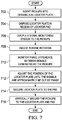
- Figure 7 shows a flow diagram for a method of adjusting the position of the electromagnetic pickups 112 in a turbine flow meter 102 in accordance with various embodiments. Though depicted sequentially as a matter of convenience, at least some of the actions shown can be performed in a different order and/or performed in parallel. Additionally, some embodiments may perform only some of the actions shown.
- the electromagnetic pickups 112 are inserted into the channels 118 of the locator plate 110.
- the channels 118 allow longitudinal movement of the pickups 112 but inhibit lateral movement of the pickups 112 independent of the locator plate 110.
- the locator plate 110 is disposed in the recess 114 of the locator pad 108.
- the recess 114 is dimensioned to allow a predetermined range of locator plate horizontal movement (e.g., lateral and, optionally, longitudinal with respect to the flow tube 102, where lateral is in the direction of the center line 124 and longitudinal is in the direction of flow).
- a signal monitoring system 604 is coupled to the electromagnetic pickups 112.
- the signal monitoring system may be an oscilloscope.
- the signal monitoring system may be a processing system (e.g., a digital computer) configured to analyze parameters (e.g., frequency, phase, etc.) of the signals produced by the pickups 112.
- rotation is induced in the turbine assembly 104.
- a fluid stream flowing at a known rate causes the turbine assembly 104 to rotate.
- the phase difference between the signals generated by the electromagnetic pickups 112 is monitored.
- the position of at least a portion of the locator plate 110 is adjusted, in block 712, until the signals generated by the electromagnetic pickups 112 exhibit a predetermined amount of phase difference.
- the predetermined amount of phase difference may be approximately 90° (e.g., 90° ⁇ 45°).
- the locator plate 110, or a portion thereof, may be adjusted laterally and/or longitudinally (with respect to the flow tube 102) to achieve the predetermined amount of phase difference between the signals.
- the locator plate 110 is secured to the locator pad 108 by the bolts 202.
- the pickups 112 are vertically secured to the locator plate 110 and the locator pad 108 by the retainer 302 and bolt 306 in block 716.
Landscapes
- Physics & Mathematics (AREA)
- Fluid Mechanics (AREA)
- General Physics & Mathematics (AREA)
- Electromagnetism (AREA)
- Measuring Volume Flow (AREA)
Claims (15)
- Turbinendurchflussmesser (100), Folgendes beinhaltend:einen Durchflussröhre (102);einen Durchflussanzeiger (104), welcher innerhalb der Durchflussröhre (102) angeordnet ist;eine Vielzahl von elektromagnetischen Aufnehmern (112), welche konfiguriert sind, um eine Drehung des Durchflussanzeigers (104) in der Durchflussröhre (102) zu erkennen;eine Positionsgeberplatte (110), in welcher die elektromagnetischen Aufnehmer (112) gesichert sind;dadurch gekennzeichnet, dass die Positionsgeberplatte (110) konfiguriert ist, um die Justierung einer seitlichen Position der elektromagnetischen Aufnehmer (112) in Bezug auf die Durchflussröhre (102) bereitzustellen; und wobeider Turbinendurchflussmesser (100) zudem eine Positionsgeberfläche (108) beinhaltet, welche konfiguriert ist, an der Durchflussröhre (102) befestigt zu werden und die Positionsgeberplatte (110) über eine Reihe von Positionsgeberplatten-Positionen entlang einer oder mehrerer Achsen zurückzuhalten.
- Turbinendurchflussmesser (100) nach Anspruch 1, bei welchem die Positionsgeberfläche (108) eine Vielzahl von Vertiefungen (116) umfasst, wobei jede Vertiefung (116) einem der Aufnehmer (112) entspricht und konfiguriert ist, um einen vorbestimmten Justierbereich der Position des Aufnehmers aufzunehmen (112).
- Turbinendurchflussmesser (100) nach Anspruch 2, bei welchem jede Vertiefung (116) eine Oberfläche (312) umfasst, welche eine axiale Position des Aufnehmers (112) innerhalb der Vertiefung (116) bestimmt.
- Turbinendurchflussmesser (100) nach Anspruch 2, bei welchem die Positionsgeberplatte (110) konfiguriert ist, um justierbar jeden der Aufnehmer (112) innerhalb der entsprechenden Vertiefung (116) der Positionsgeberfläche (108) an irgendeiner einer Vielzahl von axialen Positionen zurückzuhalten.
- Turbinendurchflussmesser (100) nach Anspruch 1, bei welchem die Positionsgeberplatte (110) ebenfalls konfiguriert ist, um die Justierung einer Längsposition des Aufnehmers (112) in Bezug auf die Durchflussröhre (102) bereitzustellen.
- Turbinendurchflussmesser (100) nach Anspruch 1, bei welchem die Positionsgeberplatte (110) konfiguriert ist, um die Justierung mindestens eines Elementes der Gruppe, bestehend aus einer seitlichen und einer Längsposition eines ersten der Aufnehmer (112) bereitzustellen, welche unabhängig von einer Position eines zweiten der Aufnehmer (112) ist.
- Turbinendurchflussmesser (100) nach Anspruch 1, bei welchem die Positionsgeberplatte (110) in Reaktion auf Aufnehmer-Positionierfehler justierbar ist, welche eine andere als eine vorbestimmte Menge an Phasendifferenz zwischen Detektionssignalen verursachen, welche durch zwei der Aufnehmer (112) erzeugt werden.
- Turbinendurchflussmesser (100) nach Anspruch 1, bei welchem die Positionsgeberplatte (110) konfiguriert ist, um die Vielzahl von elektromagnetischen Aufnehmern (112) zurückzuhalten.
- Turbinendurchflussmesser (100) nach Anspruch 1, bei welchem die Positionsgeberfläche (108) eine Vertiefung (116) umfasst, welche konfiguriert ist, um die Positionsgeberplatte (110) darin zu halten, und um es der Positionsgeberplatte (110) zu ermöglichen, innerhalb der Vertiefung (116) neu positioniert zu werden.
- Turbinendurchflussmesser (100) nach Anspruch 1, bei welchem die Positionsgeberplatte (110) und die Positionsgeberfläche (108) konfiguriert sind, um die Justierung mindestens eines Elementes der Gruppe, bestehend aus seitlicher und die Längsjustierung einer Position der Positionsgeberplatte (110) in Bezug auf die Durchflussröhre (102) zu ermöglichen; oder
wobei das Montagesystem zudem ein Rückhalteelement (302) beinhaltet, welches an der Positionsgeberplatte (110) gesichert ist, wobei das Rückhalteelement (302) zum Befestigen eines elektromagnetischen Aufnehmers (112) an der Positionsgeberplatte (110) konfiguriert ist. - Turbinendurchflussmesser (100) nach Anspruch 1, bei welchem die Positionsgeberplatte (110) konfiguriert ist, um es einem elektromagnetischen Aufnehmer (112) zu ermöglichen, in eine Vertiefung der Positionsgeberfläche (108) vorzuspringen; wobei optionsweise eine Oberfläche (312) der Vertiefung (116) eine axiale Position des elektromagnetischen Aufnehmers (112) bestimmt; oder wobei optionsweise die Positionsgeberplatte (110) konfiguriert ist, um den elektromagnetischen Aufnehmer innerhalb der Vertiefung (116) der Positionsgeberfläche (108) in irgendeiner einer Vielzahl von axialen Positionen justierbar zurückzuhalten.
- Verfahren zum Kalibrieren eines Turbinendurchflussmessers (100), wobei das Verfahren Folgendes beinhaltet:das Sichern einer Vielzahl von elektromagnetischen Aufnehmern (112) an einer Positionsgeberplatte (110);das Justieren einer Position der Positionsgeberplatte (110) in Bezug auf eine Durchflussröhre (102) des Turbinendurchflussmessers (100) bis zur Detektion der Tatsache, dass Signale, welche durch zwei der elektromagnetischen Aufnehmer (112) erzeugt werden, eine bestimmte Menge an Phasendifferenz aufweisen;dadurch gekennzeichnet, dass die Positionsgeberplatte (110) konfiguriert ist, um die Justierung einer seitlichen Position der elektromagnetischen Aufnehmer (112) in Bezug auf die Durchflussröhre (102) bereitzustellen; und wobeidas Verfahren zudem das Befestigen der Positionsgeberplatte (110) an einer Positionsgeberfläche (108) beinhaltet, welche an der Durchflussröhre (102) befestigt ist, um die Positionsgeberplatte (110) über eine Reihe von Positionsgeberplatten-Positionen entlang einer oder mehrerer Achsen zurückzuhalten.
- Verfahren nach Anspruch 12, bei welchem das Befestigen der Positionsgeberplatte (110) an der Positionsgeberfläche (108) das Positionieren der Positionsgeberplatte (110) in einer Vertiefung (114) der Positionsgeberfläche (108) beinhaltet; oder
wobei die vorbestimmte Menge an Phasendifferenz ungefähr 90 Grad beträgt. - Verfahren nach Anspruch 12, zudem beinhaltend:das Koppeln eines Signal-Monitoringsystems (604) mit den elektromagnetischen Aufnehmern (112); unddas Monitoring einer Phasendifferenz zwischen Durchflussdetektionssignalen, welche durch zwei der elektromagnetischen Aufnehmer (112) erzeugt werden; oderwobei das Justieren auf dem Monitoring basiert.
- Verfahren nach Anspruch 12, zudem beinhaltend das Justieren einer Längsposition der Positionsgeberplatte (110) in Bezug auf die Durchflussröhre (102); oder
wobei das Justieren Positionieren eines ersten der elektromagnetischen Aufnehmer (112) unabhängig von einem zweiten der elektromagnetischen Aufnehmer (112) durch ein Neupositionieren eines Abschnittes der Positionsgeberplatte (110) beinhaltet, während ein anderer Abschnitt der Positionsgeberplatte (110) stationär ist.
Applications Claiming Priority (2)
| Application Number | Priority Date | Filing Date | Title |
|---|---|---|---|
| US12/911,899 US8640523B2 (en) | 2010-10-26 | 2010-10-26 | Apparatus and method for turbine flow meter sensor adjustment |
| PCT/US2011/056515 WO2012058043A2 (en) | 2010-10-26 | 2011-10-17 | Apparatus and method for turbine flow meter sensor adjustment |
Publications (3)
| Publication Number | Publication Date |
|---|---|
| EP2633274A2 EP2633274A2 (de) | 2013-09-04 |
| EP2633274A4 EP2633274A4 (de) | 2015-08-05 |
| EP2633274B1 true EP2633274B1 (de) | 2019-12-18 |
Family
ID=45971822
Family Applications (1)
| Application Number | Title | Priority Date | Filing Date |
|---|---|---|---|
| EP11836866.1A Active EP2633274B1 (de) | 2010-10-26 | 2011-10-17 | Vorrichtung und verfahren zur einstellung eines turbinendurchflussmessersensors |
Country Status (8)
| Country | Link |
|---|---|
| US (1) | US8640523B2 (de) |
| EP (1) | EP2633274B1 (de) |
| CN (2) | CN102455209B (de) |
| BR (1) | BR112013010374B1 (de) |
| CA (1) | CA2815530C (de) |
| MX (1) | MX2013004574A (de) |
| RU (1) | RU2532895C1 (de) |
| WO (1) | WO2012058043A2 (de) |
Cited By (1)
| Publication number | Priority date | Publication date | Assignee | Title |
|---|---|---|---|---|
| EP4617629A1 (de) * | 2024-03-11 | 2025-09-17 | Engelmann Sensor GmbH | Adapterbauteil, durchflussmengenmesser und herstellungsverfahren für ein adapterbauteil |
Families Citing this family (9)
| Publication number | Priority date | Publication date | Assignee | Title |
|---|---|---|---|---|
| US8640523B2 (en) * | 2010-10-26 | 2014-02-04 | Daniel Measurement And Control, Inc. | Apparatus and method for turbine flow meter sensor adjustment |
| CN105156898B (zh) * | 2015-07-09 | 2018-03-27 | 罗美特(上海)自动化仪表股份有限公司 | 智能流量计量集控装置 |
| US9546891B1 (en) * | 2016-02-18 | 2017-01-17 | Ian Padden | Flow measuring system having a housing with a flow measurement device and a deflector plate attached over a hole in a riser |
| WO2017176573A2 (en) | 2016-04-04 | 2017-10-12 | Nordson Corporation | System and method for monitoring liquid adhesive flow |
| US10955302B2 (en) * | 2018-10-12 | 2021-03-23 | Deere & Company | Torque determination system and method |
| AT524004B1 (de) * | 2020-07-07 | 2022-07-15 | Redl Gmbh | Durchflussmessvorrichtung mit einer Prüfeinrichtung |
| DE102020133560A1 (de) * | 2020-12-15 | 2022-06-15 | Kracht Gmbh | Flußmessvorrichtung und Verfahren zur Messung des Volumenstroms eines Fluids |
| CN118548940B (zh) * | 2024-07-29 | 2024-11-15 | 江苏华海测控技术有限公司 | 一种复合式智能气体流量计 |
| CN120594785B (zh) * | 2025-08-06 | 2025-10-17 | 南京世舟分析仪器有限公司 | 一种toc在线分析系统 |
Family Cites Families (11)
| Publication number | Priority date | Publication date | Assignee | Title |
|---|---|---|---|---|
| IL30298A (en) * | 1967-07-13 | 1972-03-28 | Badger Meter Mfg Co | Flowmeter |
| US4091653A (en) * | 1977-05-18 | 1978-05-30 | Rockwell International Corporation | Turbine meter in-line checking apparatus and method |
| US4109526A (en) | 1977-08-08 | 1978-08-29 | Combustion Engineering, Inc. | Turbine meter for bi-directional measurement of fluid flow |
| SU1174753A1 (ru) * | 1984-01-19 | 1985-08-23 | Andreev Igor P | Турбинный расходомер |
| US5018384A (en) | 1989-07-21 | 1991-05-28 | Nippon Seiko Kabushiki Kaisha | Rotational speed detector |
| AU7220894A (en) * | 1993-08-13 | 1995-03-14 | Daniel Industries, Inc. | Closely coupled, dual turbine volumetric flow meter |
| US6250167B1 (en) | 1998-08-31 | 2001-06-26 | M & Fc Holding Company | Removable radio frequency sensor assembly for a turbine flow meter |
| US6397686B1 (en) * | 1999-08-09 | 2002-06-04 | Tokheim Corporation | Hall-effect sensor placed in flowmeter to measure fuel flow rate |
| US6854342B2 (en) | 2002-08-26 | 2005-02-15 | Gilbarco, Inc. | Increased sensitivity for turbine flow meter |
| KR101006265B1 (ko) | 2008-08-20 | 2011-01-06 | 창원대학교 산학협력단 | 스크류 스핀들 유량계 |
| US8640523B2 (en) * | 2010-10-26 | 2014-02-04 | Daniel Measurement And Control, Inc. | Apparatus and method for turbine flow meter sensor adjustment |
-
2010
- 2010-10-26 US US12/911,899 patent/US8640523B2/en not_active Expired - Fee Related
-
2011
- 2011-10-17 BR BR112013010374-4A patent/BR112013010374B1/pt not_active IP Right Cessation
- 2011-10-17 CA CA2815530A patent/CA2815530C/en active Active
- 2011-10-17 RU RU2013118986/28A patent/RU2532895C1/ru active
- 2011-10-17 WO PCT/US2011/056515 patent/WO2012058043A2/en not_active Ceased
- 2011-10-17 EP EP11836866.1A patent/EP2633274B1/de active Active
- 2011-10-17 MX MX2013004574A patent/MX2013004574A/es active IP Right Grant
- 2011-10-26 CN CN201110328917.0A patent/CN102455209B/zh not_active Expired - Fee Related
- 2011-10-26 CN CN2011204129189U patent/CN202853662U/zh not_active Expired - Lifetime
Non-Patent Citations (1)
| Title |
|---|
| None * |
Cited By (1)
| Publication number | Priority date | Publication date | Assignee | Title |
|---|---|---|---|---|
| EP4617629A1 (de) * | 2024-03-11 | 2025-09-17 | Engelmann Sensor GmbH | Adapterbauteil, durchflussmengenmesser und herstellungsverfahren für ein adapterbauteil |
Also Published As
| Publication number | Publication date |
|---|---|
| WO2012058043A3 (en) | 2012-06-28 |
| RU2532895C1 (ru) | 2014-11-10 |
| CN102455209A (zh) | 2012-05-16 |
| BR112013010374B1 (pt) | 2020-02-27 |
| MX2013004574A (es) | 2013-10-01 |
| EP2633274A4 (de) | 2015-08-05 |
| CA2815530C (en) | 2016-08-02 |
| CA2815530A1 (en) | 2012-05-03 |
| US20120096920A1 (en) | 2012-04-26 |
| US8640523B2 (en) | 2014-02-04 |
| CN102455209B (zh) | 2016-01-27 |
| CN202853662U (zh) | 2013-04-03 |
| WO2012058043A2 (en) | 2012-05-03 |
| BR112013010374A2 (pt) | 2016-08-02 |
| EP2633274A2 (de) | 2013-09-04 |
Similar Documents
| Publication | Publication Date | Title |
|---|---|---|
| CA2815530C (en) | Apparatus and method for turbine flow meter sensor adjustment | |
| EP2665996B1 (de) | Vorrichtung und verfahren zur bestimmung einer verdrängerposition in einem eichgerät für eine durchflussmessvorrichtung | |
| EP2205932B1 (de) | System und verfahren zur messung von installationsabmessungen für ein strömungsmesssystem | |
| US7925392B2 (en) | Aircraft vehicular propulsion system monitoring device and method | |
| US9666347B2 (en) | Magnet keeper assembly method | |
| WO2005013015A1 (en) | Peak switch detector for transit time ultrasonic meters | |
| CA1097518A (en) | Turbine meter for bi-directional measurement of fluid flow | |
| CA1325113C (en) | Flow meter | |
| EP1226405B1 (de) | Induktiver positionsdetektor | |
| US9329017B2 (en) | Alignment tool | |
| US20180340808A1 (en) | Torque Based Flowmeter Device and Method | |
| CN110207779B (zh) | 外夹式传感器参数化安装方法 | |
| CN116465292B (zh) | 一种电涡流传感器探头倾斜安装振动位移高精度检测系统及方法 | |
| CN201607256U (zh) | 一种一体可调型外夹式超声波流量计 | |
| CN114838650B (zh) | 一种基于转台的位移传感器标定装置和方法 | |
| CN216206880U (zh) | 气体流量检测用涡轮流量计的计量精准度检定装置 | |
| CN209802440U (zh) | 一种用于安装外夹式传感器的可调节固定装置 | |
| JP3114401B2 (ja) | カルマン渦流量計 | |
| CN219495318U (zh) | 一种发电机定子冷却水流量测量装置 | |
| CN107024190A (zh) | 一种用于高温环境下的非接触式位移传感器标定设备 | |
| CN118089871A (zh) | 一种流体振动与机械位移组合的质量流量计 | |
| CN121048815A (zh) | 一种壁面压力测量装置及方法 | |
| HK1158306B (en) | Fluid flow meter |
Legal Events
| Date | Code | Title | Description |
|---|---|---|---|
| PUAI | Public reference made under article 153(3) epc to a published international application that has entered the european phase |
Free format text: ORIGINAL CODE: 0009012 |
|
| 17P | Request for examination filed |
Effective date: 20130426 |
|
| AK | Designated contracting states |
Kind code of ref document: A2 Designated state(s): AL AT BE BG CH CY CZ DE DK EE ES FI FR GB GR HR HU IE IS IT LI LT LU LV MC MK MT NL NO PL PT RO RS SE SI SK SM TR |
|
| DAX | Request for extension of the european patent (deleted) | ||
| A4 | Supplementary search report drawn up and despatched |
Effective date: 20150703 |
|
| RIC1 | Information provided on ipc code assigned before grant |
Ipc: G01F 1/12 20060101ALI20150629BHEP Ipc: G01F 1/075 20060101AFI20150629BHEP Ipc: G01F 1/115 20060101ALI20150629BHEP Ipc: G01F 1/08 20060101ALI20150629BHEP |
|
| STAA | Information on the status of an ep patent application or granted ep patent |
Free format text: STATUS: EXAMINATION IS IN PROGRESS |
|
| 17Q | First examination report despatched |
Effective date: 20180622 |
|
| REG | Reference to a national code |
Ref country code: DE Ref legal event code: R079 Ref document number: 602011064142 Country of ref document: DE Free format text: PREVIOUS MAIN CLASS: G01F0001115000 Ipc: G01F0001080000 |
|
| RIC1 | Information provided on ipc code assigned before grant |
Ipc: G01F 1/12 20060101ALI20190308BHEP Ipc: G01F 25/00 20060101ALI20190308BHEP Ipc: G01F 1/08 20060101AFI20190308BHEP Ipc: G01F 1/115 20060101ALI20190308BHEP |
|
| GRAP | Despatch of communication of intention to grant a patent |
Free format text: ORIGINAL CODE: EPIDOSNIGR1 |
|
| STAA | Information on the status of an ep patent application or granted ep patent |
Free format text: STATUS: GRANT OF PATENT IS INTENDED |
|
| INTG | Intention to grant announced |
Effective date: 20190523 |
|
| GRAJ | Information related to disapproval of communication of intention to grant by the applicant or resumption of examination proceedings by the epo deleted |
Free format text: ORIGINAL CODE: EPIDOSDIGR1 |
|
| GRAS | Grant fee paid |
Free format text: ORIGINAL CODE: EPIDOSNIGR3 |
|
| GRAJ | Information related to disapproval of communication of intention to grant by the applicant or resumption of examination proceedings by the epo deleted |
Free format text: ORIGINAL CODE: EPIDOSDIGR1 |
|
| GRAL | Information related to payment of fee for publishing/printing deleted |
Free format text: ORIGINAL CODE: EPIDOSDIGR3 |
|
| STAA | Information on the status of an ep patent application or granted ep patent |
Free format text: STATUS: EXAMINATION IS IN PROGRESS |
|
| INTG | Intention to grant announced |
Effective date: 20190523 |
|
| GRAR | Information related to intention to grant a patent recorded |
Free format text: ORIGINAL CODE: EPIDOSNIGR71 |
|
| STAA | Information on the status of an ep patent application or granted ep patent |
Free format text: STATUS: GRANT OF PATENT IS INTENDED |
|
| INTC | Intention to grant announced (deleted) | ||
| GRAA | (expected) grant |
Free format text: ORIGINAL CODE: 0009210 |
|
| STAA | Information on the status of an ep patent application or granted ep patent |
Free format text: STATUS: THE PATENT HAS BEEN GRANTED |
|
| INTG | Intention to grant announced |
Effective date: 20191107 |
|
| AK | Designated contracting states |
Kind code of ref document: B1 Designated state(s): AL AT BE BG CH CY CZ DE DK EE ES FI FR GB GR HR HU IE IS IT LI LT LU LV MC MK MT NL NO PL PT RO RS SE SI SK SM TR |
|
| REG | Reference to a national code |
Ref country code: GB Ref legal event code: FG4D |
|
| REG | Reference to a national code |
Ref country code: CH Ref legal event code: EP |
|
| REG | Reference to a national code |
Ref country code: IE Ref legal event code: FG4D |
|
| REG | Reference to a national code |
Ref country code: DE Ref legal event code: R096 Ref document number: 602011064142 Country of ref document: DE |
|
| REG | Reference to a national code |
Ref country code: AT Ref legal event code: REF Ref document number: 1215107 Country of ref document: AT Kind code of ref document: T Effective date: 20200115 |
|
| REG | Reference to a national code |
Ref country code: NL Ref legal event code: FP |
|
| PG25 | Lapsed in a contracting state [announced via postgrant information from national office to epo] |
Ref country code: NO Free format text: LAPSE BECAUSE OF FAILURE TO SUBMIT A TRANSLATION OF THE DESCRIPTION OR TO PAY THE FEE WITHIN THE PRESCRIBED TIME-LIMIT Effective date: 20200318 Ref country code: GR Free format text: LAPSE BECAUSE OF FAILURE TO SUBMIT A TRANSLATION OF THE DESCRIPTION OR TO PAY THE FEE WITHIN THE PRESCRIBED TIME-LIMIT Effective date: 20200319 Ref country code: SE Free format text: LAPSE BECAUSE OF FAILURE TO SUBMIT A TRANSLATION OF THE DESCRIPTION OR TO PAY THE FEE WITHIN THE PRESCRIBED TIME-LIMIT Effective date: 20191218 Ref country code: LV Free format text: LAPSE BECAUSE OF FAILURE TO SUBMIT A TRANSLATION OF THE DESCRIPTION OR TO PAY THE FEE WITHIN THE PRESCRIBED TIME-LIMIT Effective date: 20191218 Ref country code: BG Free format text: LAPSE BECAUSE OF FAILURE TO SUBMIT A TRANSLATION OF THE DESCRIPTION OR TO PAY THE FEE WITHIN THE PRESCRIBED TIME-LIMIT Effective date: 20200318 Ref country code: FI Free format text: LAPSE BECAUSE OF FAILURE TO SUBMIT A TRANSLATION OF THE DESCRIPTION OR TO PAY THE FEE WITHIN THE PRESCRIBED TIME-LIMIT Effective date: 20191218 Ref country code: LT Free format text: LAPSE BECAUSE OF FAILURE TO SUBMIT A TRANSLATION OF THE DESCRIPTION OR TO PAY THE FEE WITHIN THE PRESCRIBED TIME-LIMIT Effective date: 20191218 |
|
| REG | Reference to a national code |
Ref country code: LT Ref legal event code: MG4D |
|
| PG25 | Lapsed in a contracting state [announced via postgrant information from national office to epo] |
Ref country code: HR Free format text: LAPSE BECAUSE OF FAILURE TO SUBMIT A TRANSLATION OF THE DESCRIPTION OR TO PAY THE FEE WITHIN THE PRESCRIBED TIME-LIMIT Effective date: 20191218 Ref country code: RS Free format text: LAPSE BECAUSE OF FAILURE TO SUBMIT A TRANSLATION OF THE DESCRIPTION OR TO PAY THE FEE WITHIN THE PRESCRIBED TIME-LIMIT Effective date: 20191218 |
|
| PG25 | Lapsed in a contracting state [announced via postgrant information from national office to epo] |
Ref country code: AL Free format text: LAPSE BECAUSE OF FAILURE TO SUBMIT A TRANSLATION OF THE DESCRIPTION OR TO PAY THE FEE WITHIN THE PRESCRIBED TIME-LIMIT Effective date: 20191218 |
|
| PG25 | Lapsed in a contracting state [announced via postgrant information from national office to epo] |
Ref country code: CZ Free format text: LAPSE BECAUSE OF FAILURE TO SUBMIT A TRANSLATION OF THE DESCRIPTION OR TO PAY THE FEE WITHIN THE PRESCRIBED TIME-LIMIT Effective date: 20191218 Ref country code: PT Free format text: LAPSE BECAUSE OF FAILURE TO SUBMIT A TRANSLATION OF THE DESCRIPTION OR TO PAY THE FEE WITHIN THE PRESCRIBED TIME-LIMIT Effective date: 20200513 Ref country code: RO Free format text: LAPSE BECAUSE OF FAILURE TO SUBMIT A TRANSLATION OF THE DESCRIPTION OR TO PAY THE FEE WITHIN THE PRESCRIBED TIME-LIMIT Effective date: 20191218 Ref country code: EE Free format text: LAPSE BECAUSE OF FAILURE TO SUBMIT A TRANSLATION OF THE DESCRIPTION OR TO PAY THE FEE WITHIN THE PRESCRIBED TIME-LIMIT Effective date: 20191218 |
|
| PG25 | Lapsed in a contracting state [announced via postgrant information from national office to epo] |
Ref country code: SM Free format text: LAPSE BECAUSE OF FAILURE TO SUBMIT A TRANSLATION OF THE DESCRIPTION OR TO PAY THE FEE WITHIN THE PRESCRIBED TIME-LIMIT Effective date: 20191218 Ref country code: IS Free format text: LAPSE BECAUSE OF FAILURE TO SUBMIT A TRANSLATION OF THE DESCRIPTION OR TO PAY THE FEE WITHIN THE PRESCRIBED TIME-LIMIT Effective date: 20200418 Ref country code: SK Free format text: LAPSE BECAUSE OF FAILURE TO SUBMIT A TRANSLATION OF THE DESCRIPTION OR TO PAY THE FEE WITHIN THE PRESCRIBED TIME-LIMIT Effective date: 20191218 |
|
| REG | Reference to a national code |
Ref country code: DE Ref legal event code: R097 Ref document number: 602011064142 Country of ref document: DE |
|
| REG | Reference to a national code |
Ref country code: AT Ref legal event code: MK05 Ref document number: 1215107 Country of ref document: AT Kind code of ref document: T Effective date: 20191218 |
|
| PLBE | No opposition filed within time limit |
Free format text: ORIGINAL CODE: 0009261 |
|
| STAA | Information on the status of an ep patent application or granted ep patent |
Free format text: STATUS: NO OPPOSITION FILED WITHIN TIME LIMIT |
|
| PG25 | Lapsed in a contracting state [announced via postgrant information from national office to epo] |
Ref country code: DK Free format text: LAPSE BECAUSE OF FAILURE TO SUBMIT A TRANSLATION OF THE DESCRIPTION OR TO PAY THE FEE WITHIN THE PRESCRIBED TIME-LIMIT Effective date: 20191218 Ref country code: ES Free format text: LAPSE BECAUSE OF FAILURE TO SUBMIT A TRANSLATION OF THE DESCRIPTION OR TO PAY THE FEE WITHIN THE PRESCRIBED TIME-LIMIT Effective date: 20191218 |
|
| 26N | No opposition filed |
Effective date: 20200921 |
|
| PG25 | Lapsed in a contracting state [announced via postgrant information from national office to epo] |
Ref country code: AT Free format text: LAPSE BECAUSE OF FAILURE TO SUBMIT A TRANSLATION OF THE DESCRIPTION OR TO PAY THE FEE WITHIN THE PRESCRIBED TIME-LIMIT Effective date: 20191218 Ref country code: SI Free format text: LAPSE BECAUSE OF FAILURE TO SUBMIT A TRANSLATION OF THE DESCRIPTION OR TO PAY THE FEE WITHIN THE PRESCRIBED TIME-LIMIT Effective date: 20191218 |
|
| PG25 | Lapsed in a contracting state [announced via postgrant information from national office to epo] |
Ref country code: IT Free format text: LAPSE BECAUSE OF FAILURE TO SUBMIT A TRANSLATION OF THE DESCRIPTION OR TO PAY THE FEE WITHIN THE PRESCRIBED TIME-LIMIT Effective date: 20191218 |
|
| PG25 | Lapsed in a contracting state [announced via postgrant information from national office to epo] |
Ref country code: PL Free format text: LAPSE BECAUSE OF FAILURE TO SUBMIT A TRANSLATION OF THE DESCRIPTION OR TO PAY THE FEE WITHIN THE PRESCRIBED TIME-LIMIT Effective date: 20191218 |
|
| REG | Reference to a national code |
Ref country code: CH Ref legal event code: PL |
|
| PG25 | Lapsed in a contracting state [announced via postgrant information from national office to epo] |
Ref country code: MC Free format text: LAPSE BECAUSE OF FAILURE TO SUBMIT A TRANSLATION OF THE DESCRIPTION OR TO PAY THE FEE WITHIN THE PRESCRIBED TIME-LIMIT Effective date: 20191218 Ref country code: LU Free format text: LAPSE BECAUSE OF NON-PAYMENT OF DUE FEES Effective date: 20201017 |
|
| REG | Reference to a national code |
Ref country code: BE Ref legal event code: MM Effective date: 20201031 |
|
| PG25 | Lapsed in a contracting state [announced via postgrant information from national office to epo] |
Ref country code: LI Free format text: LAPSE BECAUSE OF NON-PAYMENT OF DUE FEES Effective date: 20201031 Ref country code: CH Free format text: LAPSE BECAUSE OF NON-PAYMENT OF DUE FEES Effective date: 20201031 Ref country code: BE Free format text: LAPSE BECAUSE OF NON-PAYMENT OF DUE FEES Effective date: 20201031 |
|
| PG25 | Lapsed in a contracting state [announced via postgrant information from national office to epo] |
Ref country code: IE Free format text: LAPSE BECAUSE OF NON-PAYMENT OF DUE FEES Effective date: 20201017 |
|
| REG | Reference to a national code |
Ref country code: DE Ref legal event code: R081 Ref document number: 602011064142 Country of ref document: DE Owner name: DANIEL OPCO, LLC, DOVER, US Free format text: FORMER OWNER: DANIEL MEASUREMENT AND CONTROL,INC.,, HOUSTON, TEX., US |
|
| REG | Reference to a national code |
Ref country code: GB Ref legal event code: 732E Free format text: REGISTERED BETWEEN 20220127 AND 20220202 |
|
| PG25 | Lapsed in a contracting state [announced via postgrant information from national office to epo] |
Ref country code: TR Free format text: LAPSE BECAUSE OF FAILURE TO SUBMIT A TRANSLATION OF THE DESCRIPTION OR TO PAY THE FEE WITHIN THE PRESCRIBED TIME-LIMIT Effective date: 20191218 Ref country code: MT Free format text: LAPSE BECAUSE OF FAILURE TO SUBMIT A TRANSLATION OF THE DESCRIPTION OR TO PAY THE FEE WITHIN THE PRESCRIBED TIME-LIMIT Effective date: 20191218 Ref country code: CY Free format text: LAPSE BECAUSE OF FAILURE TO SUBMIT A TRANSLATION OF THE DESCRIPTION OR TO PAY THE FEE WITHIN THE PRESCRIBED TIME-LIMIT Effective date: 20191218 |
|
| PG25 | Lapsed in a contracting state [announced via postgrant information from national office to epo] |
Ref country code: MK Free format text: LAPSE BECAUSE OF FAILURE TO SUBMIT A TRANSLATION OF THE DESCRIPTION OR TO PAY THE FEE WITHIN THE PRESCRIBED TIME-LIMIT Effective date: 20191218 |
|
| REG | Reference to a national code |
Ref country code: NL Ref legal event code: PD Owner name: DANIEL OPCO, LLC; US Free format text: DETAILS ASSIGNMENT: CHANGE OF OWNER(S), ASSIGNMENT; FORMER OWNER NAME: DANIEL MEASUREMENT AND CONTROL, INC. Effective date: 20221206 |
|
| PGFP | Annual fee paid to national office [announced via postgrant information from national office to epo] |
Ref country code: NL Payment date: 20230922 Year of fee payment: 13 Ref country code: GB Payment date: 20230920 Year of fee payment: 13 |
|
| PGFP | Annual fee paid to national office [announced via postgrant information from national office to epo] |
Ref country code: FR Payment date: 20230920 Year of fee payment: 13 |
|
| PGFP | Annual fee paid to national office [announced via postgrant information from national office to epo] |
Ref country code: DE Payment date: 20230920 Year of fee payment: 13 |
|
| REG | Reference to a national code |
Ref country code: DE Ref legal event code: R119 Ref document number: 602011064142 Country of ref document: DE |
|
| REG | Reference to a national code |
Ref country code: NL Ref legal event code: MM Effective date: 20241101 |
|
| GBPC | Gb: european patent ceased through non-payment of renewal fee |
Effective date: 20241017 |
|
| PG25 | Lapsed in a contracting state [announced via postgrant information from national office to epo] |
Ref country code: DE Free format text: LAPSE BECAUSE OF NON-PAYMENT OF DUE FEES Effective date: 20250501 |
|
| PG25 | Lapsed in a contracting state [announced via postgrant information from national office to epo] |
Ref country code: GB Free format text: LAPSE BECAUSE OF NON-PAYMENT OF DUE FEES Effective date: 20241017 |
|
| PG25 | Lapsed in a contracting state [announced via postgrant information from national office to epo] |
Ref country code: NL Free format text: LAPSE BECAUSE OF NON-PAYMENT OF DUE FEES Effective date: 20241101 |
|
| PG25 | Lapsed in a contracting state [announced via postgrant information from national office to epo] |
Ref country code: FR Free format text: LAPSE BECAUSE OF NON-PAYMENT OF DUE FEES Effective date: 20241031 |