EP2633200B1 - Flow conditioner, system and method - Google Patents
Flow conditioner, system and method Download PDFInfo
- Publication number
- EP2633200B1 EP2633200B1 EP11836752.3A EP11836752A EP2633200B1 EP 2633200 B1 EP2633200 B1 EP 2633200B1 EP 11836752 A EP11836752 A EP 11836752A EP 2633200 B1 EP2633200 B1 EP 2633200B1
- Authority
- EP
- European Patent Office
- Prior art keywords
- pipe
- ramp
- flow
- ramps
- conditioner
- Prior art date
- Legal status (The legal status is an assumption and is not a legal conclusion. Google has not performed a legal analysis and makes no representation as to the accuracy of the status listed.)
- Not-in-force
Links
- 238000000034 method Methods 0.000 title claims description 15
- 239000012530 fluid Substances 0.000 claims description 87
- 238000011144 upstream manufacturing Methods 0.000 claims description 28
- 238000002156 mixing Methods 0.000 claims description 15
- 238000009826 distribution Methods 0.000 claims description 3
- 238000002604 ultrasonography Methods 0.000 description 11
- 238000003491 array Methods 0.000 description 6
- 239000000203 mixture Substances 0.000 description 5
- 230000000694 effects Effects 0.000 description 4
- 230000003068 static effect Effects 0.000 description 4
- 230000003750 conditioning effect Effects 0.000 description 3
- 238000012546 transfer Methods 0.000 description 3
- 229910000831 Steel Inorganic materials 0.000 description 2
- 238000000429 assembly Methods 0.000 description 2
- 230000001965 increasing effect Effects 0.000 description 2
- 238000009413 insulation Methods 0.000 description 2
- 230000033001 locomotion Effects 0.000 description 2
- 239000000463 material Substances 0.000 description 2
- 238000005259 measurement Methods 0.000 description 2
- 239000003921 oil Substances 0.000 description 2
- 239000010959 steel Substances 0.000 description 2
- 238000012360 testing method Methods 0.000 description 2
- 230000000712 assembly Effects 0.000 description 1
- 238000004422 calculation algorithm Methods 0.000 description 1
- 230000001143 conditioned effect Effects 0.000 description 1
- 230000002950 deficient Effects 0.000 description 1
- 230000001419 dependent effect Effects 0.000 description 1
- 238000013461 design Methods 0.000 description 1
- 238000006073 displacement reaction Methods 0.000 description 1
- 238000002474 experimental method Methods 0.000 description 1
- 239000000295 fuel oil Substances 0.000 description 1
- 239000011521 glass Substances 0.000 description 1
- 238000000265 homogenisation Methods 0.000 description 1
- 229930195733 hydrocarbon Natural products 0.000 description 1
- 150000002430 hydrocarbons Chemical class 0.000 description 1
- 230000001939 inductive effect Effects 0.000 description 1
- 238000005304 joining Methods 0.000 description 1
- 239000007788 liquid Substances 0.000 description 1
- 238000004519 manufacturing process Methods 0.000 description 1
- 239000002184 metal Substances 0.000 description 1
- 239000011490 mineral wool Substances 0.000 description 1
- 230000035945 sensitivity Effects 0.000 description 1
- 238000010200 validation analysis Methods 0.000 description 1
- 238000003466 welding Methods 0.000 description 1
Images


Classifications
-
- F—MECHANICAL ENGINEERING; LIGHTING; HEATING; WEAPONS; BLASTING
- F15—FLUID-PRESSURE ACTUATORS; HYDRAULICS OR PNEUMATICS IN GENERAL
- F15D—FLUID DYNAMICS, i.e. METHODS OR MEANS FOR INFLUENCING THE FLOW OF GASES OR LIQUIDS
- F15D1/00—Influencing flow of fluids
- F15D1/02—Influencing flow of fluids in pipes or conduits
- F15D1/04—Arrangements of guide vanes in pipe elbows or duct bends; Construction of pipe conduit elements for elbows with respect to flow, e.g. for reducing losses of flow
-
- B—PERFORMING OPERATIONS; TRANSPORTING
- B01—PHYSICAL OR CHEMICAL PROCESSES OR APPARATUS IN GENERAL
- B01F—MIXING, e.g. DISSOLVING, EMULSIFYING OR DISPERSING
- B01F25/00—Flow mixers; Mixers for falling materials, e.g. solid particles
- B01F25/40—Static mixers
- B01F25/42—Static mixers in which the mixing is affected by moving the components jointly in changing directions, e.g. in tubes provided with baffles or obstructions
- B01F25/43—Mixing tubes, e.g. wherein the material is moved in a radial or partly reversed direction
- B01F25/431—Straight mixing tubes with baffles or obstructions that do not cause substantial pressure drop; Baffles therefor
- B01F25/4316—Straight mixing tubes with baffles or obstructions that do not cause substantial pressure drop; Baffles therefor the baffles being flat pieces of material, e.g. intermeshing, fixed to the wall or fixed on a central rod
- B01F25/43161—Straight mixing tubes with baffles or obstructions that do not cause substantial pressure drop; Baffles therefor the baffles being flat pieces of material, e.g. intermeshing, fixed to the wall or fixed on a central rod composed of consecutive sections of flat pieces of material
-
- B—PERFORMING OPERATIONS; TRANSPORTING
- B01—PHYSICAL OR CHEMICAL PROCESSES OR APPARATUS IN GENERAL
- B01F—MIXING, e.g. DISSOLVING, EMULSIFYING OR DISPERSING
- B01F25/00—Flow mixers; Mixers for falling materials, e.g. solid particles
- B01F25/40—Static mixers
- B01F25/42—Static mixers in which the mixing is affected by moving the components jointly in changing directions, e.g. in tubes provided with baffles or obstructions
- B01F25/43—Mixing tubes, e.g. wherein the material is moved in a radial or partly reversed direction
- B01F25/431—Straight mixing tubes with baffles or obstructions that do not cause substantial pressure drop; Baffles therefor
- B01F25/43197—Straight mixing tubes with baffles or obstructions that do not cause substantial pressure drop; Baffles therefor characterised by the mounting of the baffles or obstructions
- B01F25/431974—Support members, e.g. tubular collars, with projecting baffles fitted inside the mixing tube or adjacent to the inner wall
-
- B—PERFORMING OPERATIONS; TRANSPORTING
- B01—PHYSICAL OR CHEMICAL PROCESSES OR APPARATUS IN GENERAL
- B01J—CHEMICAL OR PHYSICAL PROCESSES, e.g. CATALYSIS OR COLLOID CHEMISTRY; THEIR RELEVANT APPARATUS
- B01J8/00—Chemical or physical processes in general, conducted in the presence of fluids and solid particles; Apparatus for such processes
- B01J8/008—Details of the reactor or of the particulate material; Processes to increase or to retard the rate of reaction
-
- B—PERFORMING OPERATIONS; TRANSPORTING
- B01—PHYSICAL OR CHEMICAL PROCESSES OR APPARATUS IN GENERAL
- B01J—CHEMICAL OR PHYSICAL PROCESSES, e.g. CATALYSIS OR COLLOID CHEMISTRY; THEIR RELEVANT APPARATUS
- B01J8/00—Chemical or physical processes in general, conducted in the presence of fluids and solid particles; Apparatus for such processes
- B01J8/02—Chemical or physical processes in general, conducted in the presence of fluids and solid particles; Apparatus for such processes with stationary particles, e.g. in fixed beds
- B01J8/0278—Feeding reactive fluids
-
- B—PERFORMING OPERATIONS; TRANSPORTING
- B01—PHYSICAL OR CHEMICAL PROCESSES OR APPARATUS IN GENERAL
- B01J—CHEMICAL OR PHYSICAL PROCESSES, e.g. CATALYSIS OR COLLOID CHEMISTRY; THEIR RELEVANT APPARATUS
- B01J8/00—Chemical or physical processes in general, conducted in the presence of fluids and solid particles; Apparatus for such processes
- B01J8/02—Chemical or physical processes in general, conducted in the presence of fluids and solid particles; Apparatus for such processes with stationary particles, e.g. in fixed beds
- B01J8/0285—Heating or cooling the reactor
-
- B—PERFORMING OPERATIONS; TRANSPORTING
- B01—PHYSICAL OR CHEMICAL PROCESSES OR APPARATUS IN GENERAL
- B01J—CHEMICAL OR PHYSICAL PROCESSES, e.g. CATALYSIS OR COLLOID CHEMISTRY; THEIR RELEVANT APPARATUS
- B01J8/00—Chemical or physical processes in general, conducted in the presence of fluids and solid particles; Apparatus for such processes
- B01J8/02—Chemical or physical processes in general, conducted in the presence of fluids and solid particles; Apparatus for such processes with stationary particles, e.g. in fixed beds
- B01J8/04—Chemical or physical processes in general, conducted in the presence of fluids and solid particles; Apparatus for such processes with stationary particles, e.g. in fixed beds the fluid passing successively through two or more beds
- B01J8/0492—Feeding reactive fluids
-
- B—PERFORMING OPERATIONS; TRANSPORTING
- B01—PHYSICAL OR CHEMICAL PROCESSES OR APPARATUS IN GENERAL
- B01J—CHEMICAL OR PHYSICAL PROCESSES, e.g. CATALYSIS OR COLLOID CHEMISTRY; THEIR RELEVANT APPARATUS
- B01J8/00—Chemical or physical processes in general, conducted in the presence of fluids and solid particles; Apparatus for such processes
- B01J8/02—Chemical or physical processes in general, conducted in the presence of fluids and solid particles; Apparatus for such processes with stationary particles, e.g. in fixed beds
- B01J8/04—Chemical or physical processes in general, conducted in the presence of fluids and solid particles; Apparatus for such processes with stationary particles, e.g. in fixed beds the fluid passing successively through two or more beds
- B01J8/0496—Heating or cooling the reactor
-
- F—MECHANICAL ENGINEERING; LIGHTING; HEATING; WEAPONS; BLASTING
- F15—FLUID-PRESSURE ACTUATORS; HYDRAULICS OR PNEUMATICS IN GENERAL
- F15D—FLUID DYNAMICS, i.e. METHODS OR MEANS FOR INFLUENCING THE FLOW OF GASES OR LIQUIDS
- F15D1/00—Influencing flow of fluids
- F15D1/02—Influencing flow of fluids in pipes or conduits
- F15D1/06—Influencing flow of fluids in pipes or conduits by influencing the boundary layer
-
- G—PHYSICS
- G01—MEASURING; TESTING
- G01F—MEASURING VOLUME, VOLUME FLOW, MASS FLOW OR LIQUID LEVEL; METERING BY VOLUME
- G01F1/00—Measuring the volume flow or mass flow of fluid or fluent solid material wherein the fluid passes through a meter in a continuous flow
- G01F1/66—Measuring the volume flow or mass flow of fluid or fluent solid material wherein the fluid passes through a meter in a continuous flow by measuring frequency, phase shift or propagation time of electromagnetic or other waves, e.g. using ultrasonic flowmeters
- G01F1/667—Arrangements of transducers for ultrasonic flowmeters; Circuits for operating ultrasonic flowmeters
-
- G—PHYSICS
- G01—MEASURING; TESTING
- G01F—MEASURING VOLUME, VOLUME FLOW, MASS FLOW OR LIQUID LEVEL; METERING BY VOLUME
- G01F15/00—Details of, or accessories for, apparatus of groups G01F1/00 - G01F13/00 insofar as such details or appliances are not adapted to particular types of such apparatus
-
- B—PERFORMING OPERATIONS; TRANSPORTING
- B01—PHYSICAL OR CHEMICAL PROCESSES OR APPARATUS IN GENERAL
- B01J—CHEMICAL OR PHYSICAL PROCESSES, e.g. CATALYSIS OR COLLOID CHEMISTRY; THEIR RELEVANT APPARATUS
- B01J2208/00—Processes carried out in the presence of solid particles; Reactors therefor
- B01J2208/00008—Controlling the process
- B01J2208/00017—Controlling the temperature
- B01J2208/00327—Controlling the temperature by direct heat exchange
- B01J2208/00336—Controlling the temperature by direct heat exchange adding a temperature modifying medium to the reactants
- B01J2208/00353—Non-cryogenic fluids
- B01J2208/00362—Liquid
-
- B—PERFORMING OPERATIONS; TRANSPORTING
- B01—PHYSICAL OR CHEMICAL PROCESSES OR APPARATUS IN GENERAL
- B01J—CHEMICAL OR PHYSICAL PROCESSES, e.g. CATALYSIS OR COLLOID CHEMISTRY; THEIR RELEVANT APPARATUS
- B01J2208/00—Processes carried out in the presence of solid particles; Reactors therefor
- B01J2208/00008—Controlling the process
- B01J2208/00017—Controlling the temperature
- B01J2208/00327—Controlling the temperature by direct heat exchange
- B01J2208/00336—Controlling the temperature by direct heat exchange adding a temperature modifying medium to the reactants
- B01J2208/00353—Non-cryogenic fluids
- B01J2208/00371—Non-cryogenic fluids gaseous
-
- B—PERFORMING OPERATIONS; TRANSPORTING
- B01—PHYSICAL OR CHEMICAL PROCESSES OR APPARATUS IN GENERAL
- B01J—CHEMICAL OR PHYSICAL PROCESSES, e.g. CATALYSIS OR COLLOID CHEMISTRY; THEIR RELEVANT APPARATUS
- B01J2208/00—Processes carried out in the presence of solid particles; Reactors therefor
- B01J2208/00008—Controlling the process
- B01J2208/00548—Flow
- B01J2208/00557—Flow controlling the residence time inside the reactor vessel
-
- B—PERFORMING OPERATIONS; TRANSPORTING
- B01—PHYSICAL OR CHEMICAL PROCESSES OR APPARATUS IN GENERAL
- B01J—CHEMICAL OR PHYSICAL PROCESSES, e.g. CATALYSIS OR COLLOID CHEMISTRY; THEIR RELEVANT APPARATUS
- B01J2208/00—Processes carried out in the presence of solid particles; Reactors therefor
- B01J2208/00796—Details of the reactor or of the particulate material
- B01J2208/00823—Mixing elements
- B01J2208/00831—Stationary elements
- B01J2208/00849—Stationary elements outside the bed, e.g. baffles
-
- B—PERFORMING OPERATIONS; TRANSPORTING
- B01—PHYSICAL OR CHEMICAL PROCESSES OR APPARATUS IN GENERAL
- B01J—CHEMICAL OR PHYSICAL PROCESSES, e.g. CATALYSIS OR COLLOID CHEMISTRY; THEIR RELEVANT APPARATUS
- B01J2208/00—Processes carried out in the presence of solid particles; Reactors therefor
- B01J2208/00796—Details of the reactor or of the particulate material
- B01J2208/00938—Flow distribution elements
Definitions
- the present invention is related to displacing and mixing a thermal boundary layer in fluid flowing in a pipe before a transducer site in the pipe in which a transducer of an ultrasonic flow meter is disposed.
- references to the "present invention” or “invention” relate to exemplary embodiments and not necessarily to every embodiment encompassed by the appended claims.
- the present invention is related to a flow conditioner according to the preamble of claim 1 for displacing and mixing a thermal boundary layer in a laminar fluid flow in a pipe before a transducer site in the pipe in which a transducer of an ultrasonic flow meter is disposed with a first ramp and at least a second ramp in juxtaposition with the first ramp.
- Such a flow conditioner is known from US 4 600 544 A .
- the invention is also related to a method for determining the fluid flow in a pipe according to the preamble of claim 12.
- Transit time ultrasonic flowmeters are capable of high accuracy performance over a wide range of application conditions. This has led to their adoption in applications such as custody transfer of liquid hydrocarbons. In the majority of applications, the combination of velocity, pipe diameter and viscosity are such that the flow is turbulent. Turbulent flow is characterized by the presence of turbulent vortices or 'eddies' that provide cross-stream mixing of the flow.
- the fluid viscosity is greater than normal, with the result that the flow may be in the transitional or laminar regimes.
- Transitional flows typically occur in the region where Reynolds number is between 2,000 and 10,000.
- Laminar flows typically occur at Reynolds numbers below 2,000. In laminar conditions the flow essentially travels parallel to the axis of the conduit, with no cross-stream mixing. In the transitional flow regime the flow essentially switches back and forth between laminar and turbulent conditions.
- the lack of turbulent mixing means that temperature gradients can form in the fluid. If, for example, the fluid flow entering a section of pipe is at a higher temperature than the pipe itself, then the fluid directly next to the pipe wall will be cooled to the temperature of the pipe wall, and a temperature gradient will develop between the wall and the centre of the pipe.
- the form of the temperature gradient will vary depending on factors such as the flow velocity, the temperature differential, the thermal conductivity of the fluid and distance along the conduit. Typically, in the applications of interest, the temperature will change rapidly in a region close to the pipe wall.
- Transit time ultrasonic flowmeters operate by estimating flow velocity, and hence volumetric flowrate, by measuring the flight time of ultrasonic pulses.
- the ultrasonic transducers are installed in a housing that is integrated into a pipe spool such that the face of the housing is at an angle (typically 45°) to the pipe axis.
- a further aspect of flow meter design typical for high-accuracy applications is that the transducer housing will not protrude beyond the inside wall of the conduit. As such a cavity is formed in front of the housing, and the ultrasound passes through the fluid in this cavity before traversing the cross-section of the conduit and passing through a second cavity in front of the receiving transducer.
- the ultrasound When the fluid between the faces of the two transducer housings is homogenous and isothermal, the ultrasound essentially travels in a straight path. However, when thermal gradients exist in laminar flow conditions, the fluid trapped in the cavities will take on the pipe wall temperature. As the velocity of sound is a function of temperature, the result is that the ultrasound must now undergo refraction as it travels from one transducer to the other. This means that instead of traveling along a path that is straight and constant, the path taken by the ultrasound is now a function of the process fluid, temperature and flow conditions.
- Fluid flow meters are often deployed with some form of upstream flow conditioning device. In general these are deployed in order to remove non-axial components of flow velocity and/or to reshape the velocity profile across the pipe.
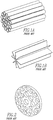
- Examples are tube bundles ( Figure 1a ) and vane-type conditioners ( Figure 1b ) which predominately aim to remove non-axial flow components by subdividing the flow into channels which are longer in the direction of the pipe axis than they are in cross-section, thus breaking up large vortices and increasing the tendency of the flow to travel parallel to the pipe axis.
- Perforated plate flow conditioners are designed with the intent of both removing non-axial flows and reshaping the axial velocity profile. This is achieved by using perforations in a plate that divide the flow into a series of jets as illustrated in Figure 2 . The flow is redistributed as a result of the pressure differential across the plate and turbulent mixing of the jets downstream of the plate produces a flow velocity distribution that is essentially uniform and free of bulk non-axial flow components.
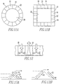
- Tab-type flow conditioners such as the proprietary Vortab device, use tabs 1 to generate large vortices that mix the flow, destroying any bulk non-axial flow components that exist upstream and redistributing the axial velocity profile. These vortices then dissipate downstream so that the velocity field presented to the meter is improved relative to disturbed conditions that may exist upstream of the device.
- An example of a tab type conditioner is shown in Figures 3a and 3b .
- Tube bundle and vane conditioners are not designed to mix the flow or disturb the boundary layer, and hence have little impact on the thermal boundary layer as it passes through.
- plate and tab-type conditioners although these can be used for mixing in turbulent flow conditions, they are ineffective at solving the problem of thermal gradients at the boundary in laminar flows. This is because (1) there are areas where the boundary layer flow can pass through relatively unaffected, and (2) in laminar flows when the boundary layer becomes separated from the wall, it tends to reattach in such a way that the thermal gradient is largely preserved.
- a conventional tab-type conditioner has a group of four tabs at each of a number of locations spaced along the axis of the conduit as illustrated in Figures 3a and 3b . Looking down the conduit, the tabs 1 from each group are aligned with one another as shown in Figure 3a . Therefore, in the zones 2 between the tabs, the boundary layer at the wall can pass through undisturbed, as shown in Figure 3a . Furthermore, when the laminar boundary layer 3 is forced off the wall by the presence of a tab, it reattaches downstream, creating a recirculation zone or dead zone 4 behind the tab. This is illustrated in Figure 4 for a single tab in two-dimensional form. The fluid trapped in the zone behind the tab will take on the temperature of the boundary layer 3 and hence a thermal gradient will still be present in the reattached boundary layer 5.
- FIG. 6 Another related field is the mixing of two fluids or the homogenization of a single fluid in a conduit, the latter including application to temperature redistribution in heat exchangers.
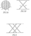
- static mixers are known that are made up of arrays of planar or curved blades. These blades are combined in assemblies, with blades arranged alternatively in two or more planes, these planes typically being at 45° to the conduit axis and 90° to one another, as illustrated in Figures 5a and 5b . Additional planes of blades are often included in a single assembly as illustrated in FIG. 6 . In a single assembly, all of the blades are parallel with respect to one another (e.g. horizontal or vertical).
- this type of mixer may be comprised of several sub-assemblies with the blades of one subassembly at a different angle to another subassembly as shown in FIGS. 7a and 7b . It is characteristic of these mixers that the blades extend completely across the conduit and when viewed looking down the axis of the conduit, they leave no unobstructed area for straight-through passage of laminar flow (e.g. FIG. 5a ).
- the invention described in this document is used to alter the flow conditions in a conduit such that an ultrasonic flow meter can perform more accurately in the laminar flow regime.
- the flow is conditioned by displacing and mixing the fluid at the periphery of the conduit such that a thermal gradient that exists directly next to the wall of the conduit is substantially eliminated. This in turn results in a more consistent relationship between the ultrasonic transit times measured by the flowmeter and actual rate of flow.
- a flow conditioner 10 for displacing and mixing fluid flow that defines an envelope 12 in a cross sectional direction in a pipe 14.
- the pipe may have transducer sites or recesses 24 for transducers of an ultrasonic flow meter 16, or the transducers may be external transducers such as used in clamp-on type meters disposed on the outside of the pipe 14, or transducers where the cavity is filled with another material.
- the conditioner may be used with a pipe in applications that do not utilize flow meters.
- the conditioner comprises a first ramp 18 adapted to be disposed in the pipe 14 and extending from the outside of the envelope 12 inward toward the center of the pipe 14 in a downstream direction with respect to the fluid flow and forming an angle between 15° and 75° relative to the pipe's inner surface 20.
- the conditioner comprises a second ramp 22 adapted to be disposed in the pipe 14 and in juxtaposition with the first ramp 18.
- the second ramp 22 extends from the outside of the envelope 12 inward toward the center of the pipe 14 in an upstream direction with respect to the fluid flow and forms an angle between 15° and 75° relative to the pipe's inner surface 20.
- the first and second ramps 18, 22 are adapted to be positioned upstream of one of the transducer sites 24, in applications where transducer sites are present.
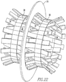
- the flow conditioner 10 includes a flange 26, as shown in figure 22 , having a face 28 which attaches to the pipe 14 and an opening 30 in the face 28 defined by an area through which fluid in the pipe 14 flows.
- the first and second ramps 18, 22 are attached to and extend from the face 28.
- the flange 26 is attached to the pipe 14 upstream of the transducer sites 24.
- the flow conditioner 10 may include a third ramp 32 adapted to be disposed in the pipe 14 and extending from the outside of the envelope 12 inward toward the center of the pipe 14 in a downstream direction with respect to the fluid flow and forming an angle between 15° and 75° relative to the pipe's inner surface 20.
- the conditioner may include a fourth ramp 34 adapted to be disposed in the pipe 14 and in juxtaposition with the third ramp 32.
- the fourth ramp 34 extends from the outside of the envelope 12 inward toward the center of the pipe 14 in an upstream direction with respect to the fluid flow and forms an angle between 0° and 90° relative to the pipe's inner surface 20.
- the third and the fourth ramps 32, 34 are attached to and extending from the face 28.
- Figure 23 shows the conditioner positioned in the pipe 14.
- the first ramp 18 and the second ramp 22 may be in spaced relationship with the third ramp 32 and the fourth ramp 34, respectively.
- the flow conditioner 10 may include a strip 38 and a fifth ramp 36 attached to and extending from the strip 38.
- the first ramp 18 is attached to and extends from the strip 38 with the strip 38 disposed between the first ramp 18 and the fifth ramp 36.
- the first ramp 18 may be in series with the second ramp 22 and the third ramp 32 may be in series with the fourth ramp 34.
- the first, second, third and fourth ramps 18, 22, 32, 34 extend up to a height of about 1/5 of the diameter of the pipe 14 from the inner surface 20 of the pipe 14.
- a ramp 18 is positioned alongside and in parallel with a second ramp 22.
- the first, second, third and fourth ramps 18, 22, 32, 34 have a surface 40 exposed to the fluid flow which is flat.
- the first, second, third and fourth ramps 18, 22, 32, 34 have a surface 40 exposed to the fluid flow which is not flat, as shown in FIGS. 17a-17f .
- the first ramp 18 may have the second ramp 22 directly behind it or offset behind it, for instance offset the distance of about the width of the ramp to the side. Additional ramps may be positioned in parallel with the first ramp 18 and with the second ramp 22 in alternating fashion so there is a space of about the width of the ramp between ramps next to each other, with the series of ramps behind the first set of ramps aligned with the spaces between the first set of ramps, as shown in FIG. 22 .
- a first set of ramps may extend upwards from the inner surface of the pipe 14 or the flange 26 with the second set of ramps extending downward to the inner surface of the pipe 14 or flange 26, with the first set of ramps essentially forming the upward slope of a hill and the second set of ramps forming the downward slope of the hill in regard to the direction of flow.
- a ramp 22 may extend continuously from the first ramp 18, have a strip 38 between them, or have a space of from about 2,54cm to 5,08cm (one to two inches) to about 0,30, 0,60, 0,91 or even 1,83m (1,2,4, 6 feet) depending on the boundary conditions and flow.
- the present invention pertains to a system for determining fluid flow in a pipe 14.
- the pipe has transducer sites that may or may not have transducer recesses 24.
- the system comprises an ultrasonic flow meter 16 having transducers that communicate with the fluid flow in the pipe 14.
- the transducers communicate with the fluid flow through the transducer recesses 24.
- the apparatus 11 comprises a flow conditioner 10 for displacing and mixing the fluid flow that defines an envelope 12 in a cross-sectional direction having a first ramp 18 disposed in the pipe 14 and extending from the outside of the envelope 12 inward toward the center of the pipe 14 in a downstream direction with respect to the fluid flow and forming an angle between 15° and 75° relative to the pipe's inner surface 20.
- the flow conditioner 10 has a second ramp 22 adapted to be disposed in the pipe 14 and in juxtaposition with the first ramp 18.
- the second ramp 22 extends from the outside of the envelope 12 inward toward the center of the pipe 14 in an upstream direction with respect to the fluid flow and forms an angle between 15° and 75° relative to the pipe's inner surface 20.
- the first and second ramps 18, 22 are adapted to be positioned upstream of one of the transducer sites 24.
- the flow conditioner 10 would typically be disposed a distance between 5 and 15 diameters of the pipe 14 upstream from the transducer sites 24, although the distance may be longer or shorter than between 5 and 15 diameters of the pipe 14, depending on the circumstances.
- the present invention pertains to a method for determining fluid flow in a pipe 14.
- the pipe 14 has a plurality of transducer sites 24.
- the method comprises the steps of displacing a thermal boundary layer in the fluid flow in proximity to the pipe's inner surface 20 with a first ramp 18 extending at an angle between 15° and 75° from the pipe's inner surface 20.
- the first ramp 18 is disposed upstream from one transducer site of the plurality of transducer sites 24.
- the present invention pertains to a method for determining fluid flow in a pipe 14.
- the method comprises the steps of displacing a thermal boundary layer in the fluid flow in proximity to the pipe's inner surface 20 with a first ramp 18 extending at an angle between 15° and 75° from the pipe's inner surface 20.
- a second ramp 22 extending at an angle between 15° and 75° from the pipe's inner surface 20 and disposed in juxtaposition with the first ramp 18.
- the first ramp 18 could be considered as pushing the fluid out from the inner surface 20 of the pipe 14 and the second ramp 22 pushing the fluid in towards the inner surface 20 of the pipe.
- the present invention is directed to a flow conditioning device, designed to improve the performance of ultrasonic flowmeters in laminar flow conditions.
- the device conditions the flow stream with an assembly of ramps designed to create radial movement to displace and mix the fluid at the wall of the conduit. Relative to the direction of flow through the conduit, the ramps slope either in towards the centre of the conduit, or out towards the wall of the conduit.
- the inward sloping ramps force the fluid in the boundary layer in towards the centre of the pipe 14, whereas the outward sloping ramps force fluid towards the wall to displace and mix with the boundary layer, as illustrated in Figures 8a, 8b, 8c and 8d .
- the method of use involves placing the conditioner in a conduit upstream of the flow meter 16 to displace and partially mix the flow in the boundary layer.
- the distance between the conditioner and the flow meter 16 is long enough to reduce the hydraulic disturbance observed at the location of the flowmeter, but short enough to ensure that significant thermal gradients are not reestablished at the pipe wall in the intervening section of conduit.
- the conduit surrounding the conditioner, the flow meter 16 itself, and the connecting conduit between the conditioner and the flowmeter would preferably be insulated such that heat transfer between the outside and the contents of the pipe 14 is minimized.
- An illustration of the method of use is shown in Figure 9 . If desired, thermal insulation 51 may be utilized.
- Figures 10a, 10b and 10c represent a transducer housing for transmitting ultrasound into a fluid as part of an ultrasonic flowmeter.
- the representation here is in two dimensions only. In reality the three dimensional geometry is generally more complex, involving a cylindrical conduit wall and cylindrical transducer housing. However, the simplified two-dimensional case serves well to illustrate the nature of the problem.
- the temperature of the fluid is homogenous, and the ultrasound travels in a direction that is perpendicular to the face 28 of the transducer housing.
- the pipe wall is hotter or colder than the fluid in the centre of the conduit. Therefore there is a layer of fluid next to the pipe wall that has a higher or lower temperature than the fluid at the centre of the pipe 14.
- the thermal boundary layer is displaced from the wall by means of a ramp. If the layer of fluid that is at a different temperature from the core is prevented from reattaching to the wall, as illustrated in Figure 10c , then the transfer of heat between that layer and the rest of the fluid will be increased. Furthermore, the detachment of the layer from the wall allows the fluid in the cavity to retain the same temperature as the fluid in the centre of the conduit. Therefore, even if there is a thin layer of fluid of different temperature present in the stream, when it the ultrasound crosses the layer refraction occurs twice, and the angle of travel is only changed within the layer, as illustrated in figure 10c .
- one array of alternating inward and outward sloping ramps may suffice.
- additional arrays of ramps placed downstream of the first array. Additional arrays can be advantageously positioned such that a second array of inward sloping ramps is positioned downstream of the first array of inward sloping ramps, such that the fluid that is displaced towards the pipe wall by the first array of outward sloping ramps is then displaced outwards by the second array.
- This arrangement is illustrated in Figure 14 .
- the width and angle of the ramps may be varied within the scope of the invention.
- the ramps may be constructed differently to achieve the same end. Examples include ramps extending up and down from a shared plateau such as shown Figures 15a, 15b, 15c and 15d or ramps that are supported by a central brace as shown in Figures 16a, 16b and 15c . Furthermore, the cross-section of the ramps could be in the form of a rectangular, v-shaped or curved channel, as illustrated in figures 17a-17f .
- FIG. 19 shows a photograph of a boundary layer flow conditioner 10 that was constructed for experimental validation of the conditioner and method.
- a control experiment was first performed using an ultrasonic flowmeter with no flow conditioner 10 disposed upstream. Tests were carried out in the laminar regime with oil temperatures of 20, 30 and 40 °C, and ambient temperature of around 20 °C.
- the meter factor which is the ratio between the indicated and actual flowrates, is strongly dependent on temperature when no flow conditioning device is used.
- 150 mm glass mineral wool insulation 51 was wrapped around the end of the pipe where the conditioner was placed, the length of pipe between the conditioner and flowmeter, and around the flowmeter itself.
- the conditioner was placed approximately 10 the pipe diameters upstream of the transducer sites.
- a second set of tests were then conducted, again in the laminar regime, with similar temperature conditions as before. As shown in FIG. 21 , it is apparent that the sensitivity of the meter factor to oil temperature is dramatically reduced when the conditioner is used.
- a 15,24cm (6") pipe 14 and meter were used.
- the conditioner consisted of two arrays of ramps welded on to each side of a flange 26 ring as shown in FIG. 26.
- the flange 26 ring was cut from a plate of 0,32cm (1/8") thick steel with an outside diameter equal to the raised face 28 outside diameter of a 15,24cm (6") pipe flange (21,59cm (8,5")) and an inside diameter of about 15,4cm (6 1/16").
- the ramp arrays were made from thin wall (approx.
- a minimum of two transducers should be used for transit time measurement. Both of these could be on the same side of the pipe 14 (same part of the circumference) but displaced from one another down the axis. In that case the ramps would have to cover only one location on the circumference upstream of the transducers. If many transducers are used, with transducer sites 24 at different locations around the pipe 14, then it is more practical to have a conditioner that extends around the entire periphery of the pipe 14, rather than just at specific locations.
- a minimum of two ramps should be positioned upstream for a single transducer site (one pushing fluid away from the wall, and the other towards). In practice, one pushing fluid away from the wall and one on either side of that pushing fluid toward the wall would be more effective (produces an effect that is symmetrical about the centre of the ramp assembly).
- the angles of the ramps lie between 15 and 75 degrees.
- the distance (or 'height') that the ramps extend from the pipe 14 wall it should be around 0.16 pipe 14 diameters or less depending on the flow conditions (not the length of the tabs, but the 'height' into the flow; see FIG. 12 ).
- a limit of 0.2 pipe diameter (or 0.2 times the maximum internal dimension for a non-round conduit) would suffice in most applications.
- the length of the ramps this is governed by their angle and the distance they extend from the wall.
- a ramp that is at an angle of 30 degrees to the wall and is to extend 0.2 diameters in towards the centre of the pipe 14 would be 0.4 diameters long (In one example, for a 15,24cm (6 inch) pipe, each 'ramp' is made up of two tabs extending from the tube, about 2,54cm (1 inch) long on either side).
- the width of the ramps should be sufficiently wide so that their main action is to displace fluid radially, rather than having it 'spill' over the sides.
- the ramps are about 1,27cm (1/2 inch) wide, equating to approximately 0.1 D. Making them less than say 0.05 D wide would result in approx 64 ramps round the circumference, and the ramps are becoming rather narrow. So a practical minimum width constraint could be stated as 0.05 times the maximum internal dimension (diameter, length of one side) of the conduit. At the other end of the scale, a width of 0.4 D would result in 8 ramps around the circumference. These represent practical guidelines, not absolute limits.
- the conditioner may be made by constructing an array of ramps from a tubular or flat piece of metal, though, it could be made from a different material such as plastic and still achieve the same end. It is also possible that it could be made by joining individual flat ramps together, say by welding.
- the conditioner may be used by being sandwiched between pipe flanges.
- the ramps could be secured in the upstream section of an integrated flow conditioner and flow meter.
- Another variant would be a pipe spool with the ramps secured inside the spool.
- the conditioner may be incorporated into the meter body, so when the meter is positioned with the pipe, the conditioner is already part of the meter assembly.
- the meter may be a reduced bore meter, such as described in U.S. Pat. No. 7,810,401 .
Landscapes
- Chemical & Material Sciences (AREA)
- Chemical Kinetics & Catalysis (AREA)
- Organic Chemistry (AREA)
- Physics & Mathematics (AREA)
- Fluid Mechanics (AREA)
- Engineering & Computer Science (AREA)
- General Physics & Mathematics (AREA)
- Dispersion Chemistry (AREA)
- Mechanical Engineering (AREA)
- General Engineering & Computer Science (AREA)
- Electromagnetism (AREA)
- Measuring Volume Flow (AREA)
Applications Claiming Priority (2)
| Application Number | Priority Date | Filing Date | Title |
|---|---|---|---|
| US12/925,558 US8347733B2 (en) | 2010-10-25 | 2010-10-25 | Conditioner, apparatus and method |
| PCT/US2011/001694 WO2012057817A1 (en) | 2010-10-25 | 2011-10-02 | Conditioner, apparatus and method |
Publications (3)
| Publication Number | Publication Date |
|---|---|
| EP2633200A1 EP2633200A1 (en) | 2013-09-04 |
| EP2633200A4 EP2633200A4 (en) | 2017-10-25 |
| EP2633200B1 true EP2633200B1 (en) | 2019-09-18 |
Family
ID=45971828
Family Applications (1)
| Application Number | Title | Priority Date | Filing Date |
|---|---|---|---|
| EP11836752.3A Not-in-force EP2633200B1 (en) | 2010-10-25 | 2011-10-02 | Flow conditioner, system and method |
Country Status (10)
| Country | Link |
|---|---|
| US (1) | US8347733B2 (pt) |
| EP (1) | EP2633200B1 (pt) |
| KR (1) | KR20130125764A (pt) |
| CN (1) | CN103210220A (pt) |
| BR (1) | BR112013009494A2 (pt) |
| CA (1) | CA2814631A1 (pt) |
| MX (1) | MX2013004573A (pt) |
| SG (1) | SG189441A1 (pt) |
| TW (1) | TW201237281A (pt) |
| WO (1) | WO2012057817A1 (pt) |
Families Citing this family (15)
| Publication number | Priority date | Publication date | Assignee | Title |
|---|---|---|---|---|
| EP2066866B1 (en) | 2006-12-15 | 2018-09-12 | Halliburton Energy Services, Inc. | Antenna coupling component measurement tool having rotating antenna configuration |
| US9003895B2 (en) * | 2010-10-25 | 2015-04-14 | Cameron International Corporation | Conditioner, apparatus and method |
| EP2732869B1 (en) * | 2012-11-20 | 2017-10-25 | Bosal Emission Control Systems NV | Mixing arrangement and method for mixing for use in an exhaust system |
| US9285288B2 (en) * | 2013-09-26 | 2016-03-15 | Dieterich Standard, Inc. | Retractable flow conditioner |
| EP3110485B1 (en) | 2014-02-28 | 2022-06-01 | Breas Medical AB | Flow sensor for ventilator |
| US9863798B2 (en) | 2015-02-27 | 2018-01-09 | Schneider Electric Systems Usa, Inc. | Systems and methods for multiphase flow metering accounting for dissolved gas |
| CN106248163B (zh) * | 2016-07-21 | 2019-01-25 | 华南理工大学 | 一种基于Etoile的叶片式流动调整器 |
| WO2018107268A1 (en) | 2016-12-12 | 2018-06-21 | Canada Pipeline Accessories, Co. Ltd. | Static mixer for fluid flow in a pipeline |
| BR112019026849A2 (pt) | 2017-06-19 | 2020-06-30 | Selas Heat Technology Company Llc | conjunto de defletor, e, conjunto de queimador. |
| MX2020005549A (es) | 2018-05-07 | 2020-08-20 | Canada Pipeline Access Co Ltd | Montaje de tuberia con mezclador estatico y acondicionador de flujo. |
| DE102018214702A1 (de) * | 2018-08-30 | 2019-09-12 | Audi Ag | Mischeranordnung |
| US11009881B2 (en) * | 2019-04-05 | 2021-05-18 | Caterpillar Paving Products Inc. | Roadway center detection for autonomous vehicle control |
| USD976384S1 (en) | 2020-01-13 | 2023-01-24 | Canada Pipeline Accessories Co., Ltd. | Static mixer for fluid flow |
| WO2021165830A1 (en) * | 2020-02-20 | 2021-08-26 | Sabic Global Technologies B.V. | Systems, devices, and methods of a flow assembly for dehydrogenation processes |
| CN113062767B (zh) * | 2021-04-12 | 2021-11-19 | 徐州中国矿大岩土工程新技术发展有限公司 | 一种自加压的水泥浆液泵送管系统 |
Family Cites Families (8)
| Publication number | Priority date | Publication date | Assignee | Title |
|---|---|---|---|---|
| US3620506A (en) * | 1970-07-07 | 1971-11-16 | Fmc Corp | Fluid-mixing device |
| US4600544A (en) * | 1982-11-29 | 1986-07-15 | Merix Corporation | Packing unit and method of making |
| ATE299392T1 (de) * | 1999-04-19 | 2005-07-15 | Sulzer Chemtech Ag | Statischer wirbelmischer und methode zur verwendung desselben |
| US6394644B1 (en) * | 1999-06-21 | 2002-05-28 | Koch-Glitsch, Inc. | Stacked static mixing elements |
| US8136980B2 (en) * | 2006-07-27 | 2012-03-20 | Komax Systems, Inc. | Meter flow conditioner |
| DE102007009890A1 (de) * | 2007-02-28 | 2008-09-04 | Arvinmeritor Emissions Technologies Gmbh | Statisches Mischelement sowie Verfahren zur Herstellung eines statischen Mischelements |
| US7823462B2 (en) * | 2007-12-14 | 2010-11-02 | Cameron International Corporation | Turbulence conditioner for transit time ultrasonic flow meters and method |
| US7810401B2 (en) | 2008-03-07 | 2010-10-12 | Cameron International Corporation | Apparatus and method for operation in the laminar, transition, and turbulent flow regimes |
-
2010
- 2010-10-25 US US12/925,558 patent/US8347733B2/en active Active
-
2011
- 2011-10-02 MX MX2013004573A patent/MX2013004573A/es not_active Application Discontinuation
- 2011-10-02 KR KR1020137011649A patent/KR20130125764A/ko not_active Application Discontinuation
- 2011-10-02 SG SG2013028857A patent/SG189441A1/en unknown
- 2011-10-02 EP EP11836752.3A patent/EP2633200B1/en not_active Not-in-force
- 2011-10-02 CA CA2814631A patent/CA2814631A1/en not_active Abandoned
- 2011-10-02 WO PCT/US2011/001694 patent/WO2012057817A1/en active Application Filing
- 2011-10-02 BR BR112013009494A patent/BR112013009494A2/pt not_active IP Right Cessation
- 2011-10-02 CN CN201180051601XA patent/CN103210220A/zh active Pending
- 2011-10-24 TW TW100138499A patent/TW201237281A/zh unknown
Non-Patent Citations (1)
| Title |
|---|
| None * |
Also Published As
| Publication number | Publication date |
|---|---|
| MX2013004573A (es) | 2013-05-22 |
| EP2633200A4 (en) | 2017-10-25 |
| CA2814631A1 (en) | 2012-05-03 |
| US20120096948A1 (en) | 2012-04-26 |
| SG189441A1 (en) | 2013-05-31 |
| US8347733B2 (en) | 2013-01-08 |
| TW201237281A (en) | 2012-09-16 |
| WO2012057817A1 (en) | 2012-05-03 |
| EP2633200A1 (en) | 2013-09-04 |
| KR20130125764A (ko) | 2013-11-19 |
| BR112013009494A2 (pt) | 2016-07-26 |
| CN103210220A (zh) | 2013-07-17 |
Similar Documents
| Publication | Publication Date | Title |
|---|---|---|
| EP2633200B1 (en) | Flow conditioner, system and method | |
| US9926952B2 (en) | Conditioner, apparatus and method | |
| US4365518A (en) | Flow straighteners in axial flowmeters | |
| JP4833522B2 (ja) | 静的ミキサ | |
| US9435674B2 (en) | Flowmeter | |
| US8806955B2 (en) | Fluid flow conditioner | |
| NL2015345B1 (en) | Heated flow conditioning systems and methods of using same. | |
| EP2908103A1 (en) | Flowmeter | |
| CN102016518A (zh) | 光滑孔、弦式时差法超声波流量计和方法 | |
| US10240958B2 (en) | Measuring tube unit and Coriolis mass flowmeter | |
| CN2935097Y (zh) | 多相计量装置用槽式孔板 | |
| CN102305753A (zh) | 一种适用于高温高压流体粘性测量的方法及装置 | |
| CN103270395B (zh) | 超声波流量测量装置 | |
| US20160282164A1 (en) | Device for measuring flow rate of fluid medium | |
| DE2713051A1 (de) | Stroemungsmesser | |
| US20160187172A1 (en) | Ultrasonic viscometer | |
| KR100935876B1 (ko) | 초음파 유속측정방법 및 초음파 유량측정방법 | |
| Safari Pour et al. | Visualisation of gas–liquid bubbly flows in a large diameter pipe with 90^ ∘∘ bend | |
| RU2157972C2 (ru) | Датчик давления для расходомера | |
| Bagdonas et al. | Triangular cross section duct for ultrasonic flow rate measurement | |
| Wang | Stokes flow through a zig-zag channel | |
| Gysling et al. | Sonar-Based Volumetric Flow Meter for Chemical and Petrochemical Applications | |
| Ragauskas et al. | 594. Optimization of ultrasound beam transmission path within measurement channel of ultrasonic flowmeter |
Legal Events
| Date | Code | Title | Description |
|---|---|---|---|
| PUAI | Public reference made under article 153(3) epc to a published international application that has entered the european phase |
Free format text: ORIGINAL CODE: 0009012 |
|
| 17P | Request for examination filed |
Effective date: 20130509 |
|
| AK | Designated contracting states |
Kind code of ref document: A1 Designated state(s): AL AT BE BG CH CY CZ DE DK EE ES FI FR GB GR HR HU IE IS IT LI LT LU LV MC MK MT NL NO PL PT RO RS SE SI SK SM TR |
|
| DAX | Request for extension of the european patent (deleted) | ||
| RA4 | Supplementary search report drawn up and despatched (corrected) |
Effective date: 20170922 |
|
| RIC1 | Information provided on ipc code assigned before grant |
Ipc: F15D 1/04 20060101AFI20170918BHEP |
|
| STAA | Information on the status of an ep patent application or granted ep patent |
Free format text: STATUS: EXAMINATION IS IN PROGRESS |
|
| 17Q | First examination report despatched |
Effective date: 20180514 |
|
| RAP1 | Party data changed (applicant data changed or rights of an application transferred) |
Owner name: CAMERON TECHNOLOGIES LIMITED |
|
| GRAP | Despatch of communication of intention to grant a patent |
Free format text: ORIGINAL CODE: EPIDOSNIGR1 |
|
| STAA | Information on the status of an ep patent application or granted ep patent |
Free format text: STATUS: GRANT OF PATENT IS INTENDED |
|
| INTG | Intention to grant announced |
Effective date: 20190503 |
|
| GRAS | Grant fee paid |
Free format text: ORIGINAL CODE: EPIDOSNIGR3 |
|
| GRAA | (expected) grant |
Free format text: ORIGINAL CODE: 0009210 |
|
| STAA | Information on the status of an ep patent application or granted ep patent |
Free format text: STATUS: THE PATENT HAS BEEN GRANTED |
|
| AK | Designated contracting states |
Kind code of ref document: B1 Designated state(s): AL AT BE BG CH CY CZ DE DK EE ES FI FR GB GR HR HU IE IS IT LI LT LU LV MC MK MT NL NO PL PT RO RS SE SI SK SM TR |
|
| REG | Reference to a national code |
Ref country code: GB Ref legal event code: FG4D |
|
| REG | Reference to a national code |
Ref country code: CH Ref legal event code: EP |
|
| REG | Reference to a national code |
Ref country code: DE Ref legal event code: R096 Ref document number: 602011062214 Country of ref document: DE |
|
| REG | Reference to a national code |
Ref country code: AT Ref legal event code: REF Ref document number: 1181651 Country of ref document: AT Kind code of ref document: T Effective date: 20191015 |
|
| REG | Reference to a national code |
Ref country code: IE Ref legal event code: FG4D |
|
| REG | Reference to a national code |
Ref country code: NL Ref legal event code: FP |
|
| PG25 | Lapsed in a contracting state [announced via postgrant information from national office to epo] |
Ref country code: BG Free format text: LAPSE BECAUSE OF FAILURE TO SUBMIT A TRANSLATION OF THE DESCRIPTION OR TO PAY THE FEE WITHIN THE PRESCRIBED TIME-LIMIT Effective date: 20191218 Ref country code: HR Free format text: LAPSE BECAUSE OF FAILURE TO SUBMIT A TRANSLATION OF THE DESCRIPTION OR TO PAY THE FEE WITHIN THE PRESCRIBED TIME-LIMIT Effective date: 20190918 Ref country code: LT Free format text: LAPSE BECAUSE OF FAILURE TO SUBMIT A TRANSLATION OF THE DESCRIPTION OR TO PAY THE FEE WITHIN THE PRESCRIBED TIME-LIMIT Effective date: 20190918 Ref country code: FI Free format text: LAPSE BECAUSE OF FAILURE TO SUBMIT A TRANSLATION OF THE DESCRIPTION OR TO PAY THE FEE WITHIN THE PRESCRIBED TIME-LIMIT Effective date: 20190918 Ref country code: SE Free format text: LAPSE BECAUSE OF FAILURE TO SUBMIT A TRANSLATION OF THE DESCRIPTION OR TO PAY THE FEE WITHIN THE PRESCRIBED TIME-LIMIT Effective date: 20190918 |
|
| REG | Reference to a national code |
Ref country code: LT Ref legal event code: MG4D Ref country code: NO Ref legal event code: T2 Effective date: 20190918 |
|
| PG25 | Lapsed in a contracting state [announced via postgrant information from national office to epo] |
Ref country code: AL Free format text: LAPSE BECAUSE OF FAILURE TO SUBMIT A TRANSLATION OF THE DESCRIPTION OR TO PAY THE FEE WITHIN THE PRESCRIBED TIME-LIMIT Effective date: 20190918 Ref country code: GR Free format text: LAPSE BECAUSE OF FAILURE TO SUBMIT A TRANSLATION OF THE DESCRIPTION OR TO PAY THE FEE WITHIN THE PRESCRIBED TIME-LIMIT Effective date: 20191219 Ref country code: RS Free format text: LAPSE BECAUSE OF FAILURE TO SUBMIT A TRANSLATION OF THE DESCRIPTION OR TO PAY THE FEE WITHIN THE PRESCRIBED TIME-LIMIT Effective date: 20190918 Ref country code: LV Free format text: LAPSE BECAUSE OF FAILURE TO SUBMIT A TRANSLATION OF THE DESCRIPTION OR TO PAY THE FEE WITHIN THE PRESCRIBED TIME-LIMIT Effective date: 20190918 |
|
| RAP2 | Party data changed (patent owner data changed or rights of a patent transferred) |
Owner name: SENSIA NETHERLANDS B.V. |
|
| REG | Reference to a national code |
Ref country code: AT Ref legal event code: MK05 Ref document number: 1181651 Country of ref document: AT Kind code of ref document: T Effective date: 20190918 |
|
| REG | Reference to a national code |
Ref country code: NO Ref legal event code: CREP Representative=s name: BRYN AARFLOT AS, STORTINGSGATA 8, 0161 OSLO, NORGE |
|
| REG | Reference to a national code |
Ref country code: DE Ref legal event code: R081 Ref document number: 602011062214 Country of ref document: DE Owner name: SENSIA NETHERLANDS B.V., NL Free format text: FORMER OWNER: CAMERON TECHNOLOGIES LIMITED, THE HAGUE, NL |
|
| PG25 | Lapsed in a contracting state [announced via postgrant information from national office to epo] |
Ref country code: RO Free format text: LAPSE BECAUSE OF FAILURE TO SUBMIT A TRANSLATION OF THE DESCRIPTION OR TO PAY THE FEE WITHIN THE PRESCRIBED TIME-LIMIT Effective date: 20190918 Ref country code: IT Free format text: LAPSE BECAUSE OF FAILURE TO SUBMIT A TRANSLATION OF THE DESCRIPTION OR TO PAY THE FEE WITHIN THE PRESCRIBED TIME-LIMIT Effective date: 20190918 Ref country code: EE Free format text: LAPSE BECAUSE OF FAILURE TO SUBMIT A TRANSLATION OF THE DESCRIPTION OR TO PAY THE FEE WITHIN THE PRESCRIBED TIME-LIMIT Effective date: 20190918 Ref country code: PT Free format text: LAPSE BECAUSE OF FAILURE TO SUBMIT A TRANSLATION OF THE DESCRIPTION OR TO PAY THE FEE WITHIN THE PRESCRIBED TIME-LIMIT Effective date: 20200120 Ref country code: AT Free format text: LAPSE BECAUSE OF FAILURE TO SUBMIT A TRANSLATION OF THE DESCRIPTION OR TO PAY THE FEE WITHIN THE PRESCRIBED TIME-LIMIT Effective date: 20190918 Ref country code: PL Free format text: LAPSE BECAUSE OF FAILURE TO SUBMIT A TRANSLATION OF THE DESCRIPTION OR TO PAY THE FEE WITHIN THE PRESCRIBED TIME-LIMIT Effective date: 20190918 Ref country code: ES Free format text: LAPSE BECAUSE OF FAILURE TO SUBMIT A TRANSLATION OF THE DESCRIPTION OR TO PAY THE FEE WITHIN THE PRESCRIBED TIME-LIMIT Effective date: 20190918 |
|
| PG25 | Lapsed in a contracting state [announced via postgrant information from national office to epo] |
Ref country code: CZ Free format text: LAPSE BECAUSE OF FAILURE TO SUBMIT A TRANSLATION OF THE DESCRIPTION OR TO PAY THE FEE WITHIN THE PRESCRIBED TIME-LIMIT Effective date: 20190918 Ref country code: SK Free format text: LAPSE BECAUSE OF FAILURE TO SUBMIT A TRANSLATION OF THE DESCRIPTION OR TO PAY THE FEE WITHIN THE PRESCRIBED TIME-LIMIT Effective date: 20190918 Ref country code: IS Free format text: LAPSE BECAUSE OF FAILURE TO SUBMIT A TRANSLATION OF THE DESCRIPTION OR TO PAY THE FEE WITHIN THE PRESCRIBED TIME-LIMIT Effective date: 20200224 Ref country code: SM Free format text: LAPSE BECAUSE OF FAILURE TO SUBMIT A TRANSLATION OF THE DESCRIPTION OR TO PAY THE FEE WITHIN THE PRESCRIBED TIME-LIMIT Effective date: 20190918 |
|
| REG | Reference to a national code |
Ref country code: CH Ref legal event code: PL |
|
| REG | Reference to a national code |
Ref country code: DE Ref legal event code: R097 Ref document number: 602011062214 Country of ref document: DE |
|
| REG | Reference to a national code |
Ref country code: GB Ref legal event code: 732E Free format text: REGISTERED BETWEEN 20200528 AND 20200603 |
|
| REG | Reference to a national code |
Ref country code: NL Ref legal event code: PD Owner name: SENSIA NETHERLANDS B.V.; NL Free format text: DETAILS ASSIGNMENT: CHANGE OF OWNER(S), ASSIGNMENT; FORMER OWNER NAME: CAMERON TECHNOLOGIES LIMITED Effective date: 20200609 |
|
| PLBE | No opposition filed within time limit |
Free format text: ORIGINAL CODE: 0009261 |
|
| STAA | Information on the status of an ep patent application or granted ep patent |
Free format text: STATUS: NO OPPOSITION FILED WITHIN TIME LIMIT |
|
| PG2D | Information on lapse in contracting state deleted |
Ref country code: IS |
|
| PG25 | Lapsed in a contracting state [announced via postgrant information from national office to epo] |
Ref country code: DK Free format text: LAPSE BECAUSE OF FAILURE TO SUBMIT A TRANSLATION OF THE DESCRIPTION OR TO PAY THE FEE WITHIN THE PRESCRIBED TIME-LIMIT Effective date: 20190918 Ref country code: LI Free format text: LAPSE BECAUSE OF NON-PAYMENT OF DUE FEES Effective date: 20191031 Ref country code: CH Free format text: LAPSE BECAUSE OF NON-PAYMENT OF DUE FEES Effective date: 20191031 Ref country code: LU Free format text: LAPSE BECAUSE OF NON-PAYMENT OF DUE FEES Effective date: 20191002 Ref country code: IS Free format text: LAPSE BECAUSE OF FAILURE TO SUBMIT A TRANSLATION OF THE DESCRIPTION OR TO PAY THE FEE WITHIN THE PRESCRIBED TIME-LIMIT Effective date: 20200119 |
|
| REG | Reference to a national code |
Ref country code: BE Ref legal event code: MM Effective date: 20191031 |
|
| 26N | No opposition filed |
Effective date: 20200619 |
|
| PG25 | Lapsed in a contracting state [announced via postgrant information from national office to epo] |
Ref country code: MC Free format text: LAPSE BECAUSE OF FAILURE TO SUBMIT A TRANSLATION OF THE DESCRIPTION OR TO PAY THE FEE WITHIN THE PRESCRIBED TIME-LIMIT Effective date: 20190918 Ref country code: SI Free format text: LAPSE BECAUSE OF FAILURE TO SUBMIT A TRANSLATION OF THE DESCRIPTION OR TO PAY THE FEE WITHIN THE PRESCRIBED TIME-LIMIT Effective date: 20190918 Ref country code: BE Free format text: LAPSE BECAUSE OF NON-PAYMENT OF DUE FEES Effective date: 20191031 |
|
| PG25 | Lapsed in a contracting state [announced via postgrant information from national office to epo] |
Ref country code: IE Free format text: LAPSE BECAUSE OF NON-PAYMENT OF DUE FEES Effective date: 20191002 |
|
| PG25 | Lapsed in a contracting state [announced via postgrant information from national office to epo] |
Ref country code: CY Free format text: LAPSE BECAUSE OF FAILURE TO SUBMIT A TRANSLATION OF THE DESCRIPTION OR TO PAY THE FEE WITHIN THE PRESCRIBED TIME-LIMIT Effective date: 20190918 |
|
| PG25 | Lapsed in a contracting state [announced via postgrant information from national office to epo] |
Ref country code: HU Free format text: LAPSE BECAUSE OF FAILURE TO SUBMIT A TRANSLATION OF THE DESCRIPTION OR TO PAY THE FEE WITHIN THE PRESCRIBED TIME-LIMIT; INVALID AB INITIO Effective date: 20111002 Ref country code: MT Free format text: LAPSE BECAUSE OF FAILURE TO SUBMIT A TRANSLATION OF THE DESCRIPTION OR TO PAY THE FEE WITHIN THE PRESCRIBED TIME-LIMIT Effective date: 20190918 |
|
| PGFP | Annual fee paid to national office [announced via postgrant information from national office to epo] |
Ref country code: GB Payment date: 20210930 Year of fee payment: 11 |
|
| PGFP | Annual fee paid to national office [announced via postgrant information from national office to epo] |
Ref country code: NL Payment date: 20211014 Year of fee payment: 11 |
|
| PGFP | Annual fee paid to national office [announced via postgrant information from national office to epo] |
Ref country code: NO Payment date: 20211011 Year of fee payment: 11 Ref country code: DE Payment date: 20211005 Year of fee payment: 11 |
|
| PGFP | Annual fee paid to national office [announced via postgrant information from national office to epo] |
Ref country code: FR Payment date: 20211018 Year of fee payment: 11 |
|
| PG25 | Lapsed in a contracting state [announced via postgrant information from national office to epo] |
Ref country code: TR Free format text: LAPSE BECAUSE OF FAILURE TO SUBMIT A TRANSLATION OF THE DESCRIPTION OR TO PAY THE FEE WITHIN THE PRESCRIBED TIME-LIMIT Effective date: 20190918 |
|
| PG25 | Lapsed in a contracting state [announced via postgrant information from national office to epo] |
Ref country code: MK Free format text: LAPSE BECAUSE OF FAILURE TO SUBMIT A TRANSLATION OF THE DESCRIPTION OR TO PAY THE FEE WITHIN THE PRESCRIBED TIME-LIMIT Effective date: 20190918 |
|
| REG | Reference to a national code |
Ref country code: DE Ref legal event code: R119 Ref document number: 602011062214 Country of ref document: DE |
|
| REG | Reference to a national code |
Ref country code: NO Ref legal event code: MMEP |
|
| REG | Reference to a national code |
Ref country code: NL Ref legal event code: MM Effective date: 20221101 |
|
| GBPC | Gb: european patent ceased through non-payment of renewal fee |
Effective date: 20221002 |
|
| PG25 | Lapsed in a contracting state [announced via postgrant information from national office to epo] |
Ref country code: NO Free format text: LAPSE BECAUSE OF NON-PAYMENT OF DUE FEES Effective date: 20221031 Ref country code: NL Free format text: LAPSE BECAUSE OF NON-PAYMENT OF DUE FEES Effective date: 20221101 Ref country code: FR Free format text: LAPSE BECAUSE OF NON-PAYMENT OF DUE FEES Effective date: 20221031 Ref country code: DE Free format text: LAPSE BECAUSE OF NON-PAYMENT OF DUE FEES Effective date: 20230503 |
|
| PG25 | Lapsed in a contracting state [announced via postgrant information from national office to epo] |
Ref country code: GB Free format text: LAPSE BECAUSE OF NON-PAYMENT OF DUE FEES Effective date: 20221002 |