EP2632763B1 - Vehicle occupant support - Google Patents
Vehicle occupant support Download PDFInfo
- Publication number
- EP2632763B1 EP2632763B1 EP11761169.9A EP11761169A EP2632763B1 EP 2632763 B1 EP2632763 B1 EP 2632763B1 EP 11761169 A EP11761169 A EP 11761169A EP 2632763 B1 EP2632763 B1 EP 2632763B1
- Authority
- EP
- European Patent Office
- Prior art keywords
- modular
- occupant
- supports
- vehicle
- tier
- Prior art date
- Legal status (The legal status is an assumption and is not a legal conclusion. Google has not performed a legal analysis and makes no representation as to the accuracy of the status listed.)
- Active
Links
- 238000011068 loading method Methods 0.000 claims description 23
- 230000007246 mechanism Effects 0.000 claims description 4
- QVGXLLKOCUKJST-UHFFFAOYSA-N atomic oxygen Chemical compound [O] QVGXLLKOCUKJST-UHFFFAOYSA-N 0.000 claims description 3
- 229910052760 oxygen Inorganic materials 0.000 claims description 3
- 239000001301 oxygen Substances 0.000 claims description 3
- 230000003472 neutralizing effect Effects 0.000 claims description 2
- 230000004913 activation Effects 0.000 claims 1
- 230000003028 elevating effect Effects 0.000 claims 1
- 230000000452 restraining effect Effects 0.000 claims 1
- 241001669679 Eleotris Species 0.000 description 9
- 238000012423 maintenance Methods 0.000 description 3
- 230000003068 static effect Effects 0.000 description 3
- 241000264877 Hippospongia communis Species 0.000 description 2
- 230000004308 accommodation Effects 0.000 description 2
- 230000008901 benefit Effects 0.000 description 2
- 239000000463 material Substances 0.000 description 2
- 238000000034 method Methods 0.000 description 2
- 230000036544 posture Effects 0.000 description 2
- 230000009471 action Effects 0.000 description 1
- 238000005452 bending Methods 0.000 description 1
- 230000008859 change Effects 0.000 description 1
- 230000008569 process Effects 0.000 description 1
- 230000001681 protective effect Effects 0.000 description 1
- 230000002629 repopulating effect Effects 0.000 description 1
- 230000008685 targeting Effects 0.000 description 1
Images


Classifications
-
- B—PERFORMING OPERATIONS; TRANSPORTING
- B60—VEHICLES IN GENERAL
- B60N—SEATS SPECIALLY ADAPTED FOR VEHICLES; VEHICLE PASSENGER ACCOMMODATION NOT OTHERWISE PROVIDED FOR
- B60N2/00—Seats specially adapted for vehicles; Arrangement or mounting of seats in vehicles
- B60N2/24—Seats specially adapted for vehicles; Arrangement or mounting of seats in vehicles for particular purposes or particular vehicles
- B60N2/42—Seats specially adapted for vehicles; Arrangement or mounting of seats in vehicles for particular purposes or particular vehicles the seat constructed to protect the occupant from the effect of abnormal g-forces, e.g. crash or safety seats
- B60N2/427—Seats or parts thereof displaced during a crash
-
- B—PERFORMING OPERATIONS; TRANSPORTING
- B60—VEHICLES IN GENERAL
- B60N—SEATS SPECIALLY ADAPTED FOR VEHICLES; VEHICLE PASSENGER ACCOMMODATION NOT OTHERWISE PROVIDED FOR
- B60N2/00—Seats specially adapted for vehicles; Arrangement or mounting of seats in vehicles
- B60N2/005—Arrangement or mounting of seats in vehicles, e.g. dismountable auxiliary seats
- B60N2/01—Arrangement of seats relative to one another
-
- B—PERFORMING OPERATIONS; TRANSPORTING
- B60—VEHICLES IN GENERAL
- B60N—SEATS SPECIALLY ADAPTED FOR VEHICLES; VEHICLE PASSENGER ACCOMMODATION NOT OTHERWISE PROVIDED FOR
- B60N2/00—Seats specially adapted for vehicles; Arrangement or mounting of seats in vehicles
- B60N2/24—Seats specially adapted for vehicles; Arrangement or mounting of seats in vehicles for particular purposes or particular vehicles
- B60N2/26—Seats specially adapted for vehicles; Arrangement or mounting of seats in vehicles for particular purposes or particular vehicles for children
- B60N2/265—Adaptations for seat belts
-
- B—PERFORMING OPERATIONS; TRANSPORTING
- B60—VEHICLES IN GENERAL
- B60N—SEATS SPECIALLY ADAPTED FOR VEHICLES; VEHICLE PASSENGER ACCOMMODATION NOT OTHERWISE PROVIDED FOR
- B60N2/00—Seats specially adapted for vehicles; Arrangement or mounting of seats in vehicles
- B60N2/24—Seats specially adapted for vehicles; Arrangement or mounting of seats in vehicles for particular purposes or particular vehicles
- B60N2/26—Seats specially adapted for vehicles; Arrangement or mounting of seats in vehicles for particular purposes or particular vehicles for children
- B60N2/28—Seats readily mountable on, and dismountable from, existing seats or other parts of the vehicle
- B60N2/2803—Adaptations for seat belts
- B60N2/2806—Adaptations for seat belts for securing the child seat to the vehicle
-
- B—PERFORMING OPERATIONS; TRANSPORTING
- B60—VEHICLES IN GENERAL
- B60N—SEATS SPECIALLY ADAPTED FOR VEHICLES; VEHICLE PASSENGER ACCOMMODATION NOT OTHERWISE PROVIDED FOR
- B60N2/00—Seats specially adapted for vehicles; Arrangement or mounting of seats in vehicles
- B60N2/24—Seats specially adapted for vehicles; Arrangement or mounting of seats in vehicles for particular purposes or particular vehicles
- B60N2/26—Seats specially adapted for vehicles; Arrangement or mounting of seats in vehicles for particular purposes or particular vehicles for children
- B60N2/28—Seats readily mountable on, and dismountable from, existing seats or other parts of the vehicle
- B60N2/2803—Adaptations for seat belts
- B60N2/2812—Adaptations for seat belts for securing the child to the child seat
-
- B—PERFORMING OPERATIONS; TRANSPORTING
- B60—VEHICLES IN GENERAL
- B60N—SEATS SPECIALLY ADAPTED FOR VEHICLES; VEHICLE PASSENGER ACCOMMODATION NOT OTHERWISE PROVIDED FOR
- B60N2/00—Seats specially adapted for vehicles; Arrangement or mounting of seats in vehicles
- B60N2/24—Seats specially adapted for vehicles; Arrangement or mounting of seats in vehicles for particular purposes or particular vehicles
- B60N2/26—Seats specially adapted for vehicles; Arrangement or mounting of seats in vehicles for particular purposes or particular vehicles for children
- B60N2/28—Seats readily mountable on, and dismountable from, existing seats or other parts of the vehicle
- B60N2/2884—Seats readily mountable on, and dismountable from, existing seats or other parts of the vehicle with protection systems against abnormal g-forces
-
- B—PERFORMING OPERATIONS; TRANSPORTING
- B60—VEHICLES IN GENERAL
- B60N—SEATS SPECIALLY ADAPTED FOR VEHICLES; VEHICLE PASSENGER ACCOMMODATION NOT OTHERWISE PROVIDED FOR
- B60N2/00—Seats specially adapted for vehicles; Arrangement or mounting of seats in vehicles
- B60N2/24—Seats specially adapted for vehicles; Arrangement or mounting of seats in vehicles for particular purposes or particular vehicles
- B60N2/32—Seats specially adapted for vehicles; Arrangement or mounting of seats in vehicles for particular purposes or particular vehicles convertible for other use
- B60N2/34—Seats specially adapted for vehicles; Arrangement or mounting of seats in vehicles for particular purposes or particular vehicles convertible for other use into a bed
-
- B—PERFORMING OPERATIONS; TRANSPORTING
- B60—VEHICLES IN GENERAL
- B60N—SEATS SPECIALLY ADAPTED FOR VEHICLES; VEHICLE PASSENGER ACCOMMODATION NOT OTHERWISE PROVIDED FOR
- B60N2/00—Seats specially adapted for vehicles; Arrangement or mounting of seats in vehicles
- B60N2/24—Seats specially adapted for vehicles; Arrangement or mounting of seats in vehicles for particular purposes or particular vehicles
- B60N2/42—Seats specially adapted for vehicles; Arrangement or mounting of seats in vehicles for particular purposes or particular vehicles the seat constructed to protect the occupant from the effect of abnormal g-forces, e.g. crash or safety seats
-
- B—PERFORMING OPERATIONS; TRANSPORTING
- B64—AIRCRAFT; AVIATION; COSMONAUTICS
- B64D—EQUIPMENT FOR FITTING IN OR TO AIRCRAFT; FLIGHT SUITS; PARACHUTES; ARRANGEMENTS OR MOUNTING OF POWER PLANTS OR PROPULSION TRANSMISSIONS IN AIRCRAFT
- B64D11/00—Passenger or crew accommodation; Flight-deck installations not otherwise provided for
- B64D11/06—Arrangements of seats, or adaptations or details specially adapted for aircraft seats
- B64D11/0601—Arrangement of seats for non-standard seating layouts, e.g. seats staggered horizontally or vertically, arranged in an angled or fishbone layout, or facing in other directions than the direction of flight
-
- B—PERFORMING OPERATIONS; TRANSPORTING
- B64—AIRCRAFT; AVIATION; COSMONAUTICS
- B64D—EQUIPMENT FOR FITTING IN OR TO AIRCRAFT; FLIGHT SUITS; PARACHUTES; ARRANGEMENTS OR MOUNTING OF POWER PLANTS OR PROPULSION TRANSMISSIONS IN AIRCRAFT
- B64D11/00—Passenger or crew accommodation; Flight-deck installations not otherwise provided for
- B64D11/06—Arrangements of seats, or adaptations or details specially adapted for aircraft seats
- B64D11/062—Belts or other passenger restraint means for passenger seats
Definitions
- the present invention provides a new structure and passenger transport paradigm for accommodating passengers in a vehicle with particular attention paid to safety, utility and provides new features for utility.
- the present inventions provide a new structure and passenger transport paradigm for accommodating passengers in a vehicle with particular attention paid to safety, utility and comfort.
- FIG. 1 Background of the present invention includes seating arrangements that are tiered in vehicles.
- UK Patent Application GB 2 350 828 which discloses a vehicle for railway passenger accommodation that is two tiered.
- Fig 2 , Fig 3 Fig 4 illustrates seats that are placed adjoining each other in two tiers with access using common stairways for the upper tier occupants.
- the seats are oriented to be in the direction of the vehicle axis of motion alongside aisles for access.
- the seats on the second tier are offset in the direction of the aisle (the facing direction of the occupants), with regard to the seats of the first tier.
- the embodiment of the AirSleeper shown may be deployed at an angle to the axis of the aircraft.
- the design takes advantage of the longer and shorter sides of each of the sleepers to help with the ergonomics of the sleepers.
- the longer side is used to support the stairs to the upper tier and thereby gets the stairs as far away from the lower tier occupant as follows.
- the embodiment also gets the leg space of upper tier occupant to be adjoining the sidewall of the lower tier occupant space thereby giving a wider space for egress and ingress of the lower tier occupant targeting the shorter side of that occupant's sleeper.
- the Airsleepers are designed to be modular and in some of the embodiments have a dovetail structure as shown for added strength, creating among them a stiff honey comb structure that will be resilient to crash loadings substantially axially to the aircraft Egress and ingress is facilitated with a handle that is recessing into the wall of the modular housing.
- the upper tier in this embodiment is open and may have a support member of the monitor and the modular oxygen supply as shown for example in Fig 1- 6 .
- This embodiment may have static arm rests that are attached to the modular support structure.
- the actuation by the pivotally supported linear actuator pushes or pulls the pivot between the seat back and the seat bottom.
- the seat back is forced to move along an arc as it has a pivot tot eh fixed structure higher along its length. Therefore, the seat bottom end moves in an arc.
- the front of the seat bottom maybe attached to the fixed structure with a sliding mechanisms that may be designed to give the seat bottom the preferred inclination to the seat back at different postures. therefore the slide guide or slot may be a curved to achieve this .
- the leg rest in this embodiment retracts under the seat bottom. It may be actuated by a separate manual or electric actuator, or an extension the actuator driving the seat position, by using limit switches to activate latches that allow the head of the actuator to move along the seat bottom once it has paused the seat to a horizontal position and it ash been locked in that place following the action of limit switches.
- the seat back has a novel support structure that is shaped to accommodate the bending stresses during a crash loading.
- the orientation of the occupant will be facing slightly backwards at some angle and so the long side of the seat back will be the impact side and will therefore have the head of the occupant closer to this side that will benefit the occupant with regard to safety.
- the embodiments do not show the foot frame or support elements that support the Air sleepers. These are the subject of prior applications.
- the AirSleeper is an accommodation for passengers in aircraft that allows deployment as a tiered bed and in most embodiments a seat as well.
- the Air Sleeper may be implemented in a modular fashion and each passenger has a module that has a structure that locks to the adjoining similar AirSleeper structures and the support frame below, thereby creating a rigid honeycomb like structure to resist loading along the axis of the aircraft.
- Fig 2-1 shows the AirSleeper structural module with ledges or flanges (that may be retractable in some embodiments) such that the flanges on the rear side of the AirSleeper with regard to the motion of the aircraft face upwards to support a downward force from the adjoining AirSleeper support module and the flanges on the front side of each of the Air Sleeper modules face downwards to support an upward force from the adjoining AirSleeper module.
- ledges or flanges that may be retractable in some embodiments
- Fig 2-11 shows latches that may be retracted for the same purpose. Notably retraction of such latches will enable the removal of one or more of the AirSleepers for maintenance or reconfiguration without removing the entire Bank of Air Sleepers in a locked row.
- the latches can use techniques for locking and retraction well disclosed in the background art
- Fig 2-2 shows an enhancement for improving the structural rigidity of the AirSleeper during crash loadings by creating a shear plane with the feature that separates the leg area of the upper tier from the lower occupant space.
- This feature may be connected on its side and top to the lower tier AirSleeper structure to perform this function.
- the connection may be extended to the further side of the AirSleeper to increase such rigidity further.
- this feature may be connected to the steps that enable egress and ingress for the occupant in the upper tier of the Air Sleeper, thereby further increasing the rigidity under crash loading conditions for each of the AirSleeper modules.
- Some embodiments may have a rear wall for the steps that can increase the shear plane further down to further increase the rigidity offered.
- Fig 2-8 Provides yet another features for addressing the crash loading conditions.
- the ledges shown on the rear of each foot frame will provide upward forces on the adjoining foot frame and the ledges shown on the front of each foot frame provides a downward force on the adjoining foot frame, these forces thereby neutralizing each other in an array of such foot frames assembled end to end and as a result reducing the forces on the tracks to the residual force.
- the surface of the contact points of the foot frames to each other may have a compressible material thereby creating some force equalization between the foot frames to accommodate engineering inaccuracies.
- AirSleeper structure modules may be of different widths and therefore may require support points that accommodate varying spacing requirements.
- the support points are spaced to accommodate multiple standard widths of Ari Sleeper.
- Many embodiments will use load limiters between the Foot frames and the AirSleeper modules.
- elongated support points for latches to the seat tracks.
- Such elongated support points may house flexible or compressible material surrounding the eye that is attached to the support point.
- Such flexibility enabled with such an arrangement or any other load limiting arrangement well disclosed in the background art will allow for load equalization across the latch points in the event of a crash loading condition or in the event of flexing of the Air frame Fig. 2-3, 2-4 , 2-5, 2-6, 2-7, 2-9 , 2-9A , 3-1, 3-2, 3-3 and 3-4 do not fall under the scope of protction
Description
- The present invention provides a new structure and passenger transport paradigm for accommodating passengers in a vehicle with particular attention
paid to safety, utility and provides new features for utility. - The present inventions provide a new structure and passenger transport paradigm for accommodating passengers in a vehicle with
particular attention paid to safety, utility and comfort. - The Drawings illustrate embodiments of the inventions. These features and more are described below. The invention relates to the referenced filed applications.
- 101 -Stairs
- 102- Leg Rest- retractable or pivoted.
- 103 - Seat Bottom
- 1 04 - Seat back
- 105 - Support Structure
- 106 - Arm Rests
- 107 -Actuator for seatback and bottom actuation.
- 108 - Lateral support for head under crash loadings
- 109 - handle for egress and ingress
- 110 - Staggered Upper tier accommodates egress ingress of lower tier.
- 111 -Front edge inclined to the Sleeper direction for the Aisle direction
- 112 -Actuator Shaft
- 113 - Seat Back Pivot
- 114- Fixed support for seatback pivot
- 115 - Pivotal support for actuator
- 116- Seat Back to Seat Bottom pivotal connection
- 117 - Slider slot for Seat bottom front slide (may be a non-linear profile)
- 118 - Sliding pin, roller or slide attached to seat bottom guided by slot
- 119 - Seat Bottom
- 120- Leg Rest- retractable in this embodiment (may also be pivotally supported to pivot down)
-
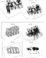
Fig 1-1 : shows four views of the AirSleeper for the upper tier in the flat bed position. This embodiment has an open top and a support element for the screen and/or oxygen system. -
Fig 1-2 : Shows the upper tier AirSleeper in the recline position -
Fig 1-3 is the same asFig 1-2 except that the internal parts are shown. The operation of the actuator is clearly seen in this view. -
Fig 1-4 Shows the same embodiment in the sit up position -
Fig 1-5 shows the lower tier with support at the top for the upper tier. -
Fig1- 6 : show the modular interlocking of the lower and upper tier Air Sleepers. It also illustrates the staggering of the upper tier sleepers to enable access for the lower tier sleepers The Step are mounted on the sidewall of the lower sleepers in many embodiments so that obstruction to the egress ingress of the lower tier occupant is minimized. The back wall of the leg space can be used for the video monitor of the lower tier occupant. -
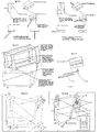
Fig 1-12 shows the mechanism and actuation of the seat in one of the embodiments. A single actuator can both change the posture of the seat from flat bed to situp and also push out the leg rest when the bed is in the Hat position. A latch arrangement many of which are well disclosed in the background art, will allow the pivotal attachment of the actuator shaft to the seat bottom and the seat back to slide along the seat bottom once it is in the flat position and thereby enable the actuator shaft to push out the leg rest. More conventional designs can have separate actuators for the seat
back and bottom as shown to the separate actuator (either manual or mechanical) to actuate the sliding leg rest.
The actuation of the pivot between the seat back and bottom makes the seat l>ack pivot on its staticpivotal point 113 attached to the structure and moves the bottom of the seat back along an arc, carrying with it the back of the seat bottom. Near the front of the seat bottom there is a slidable attachment to the static structure that moves the front of the seat along a path for the optimal inclination of the seat bottom. The sliding path may be designed to be a curve to optimize the seat bottom inclination. The seat back has a protective side in many embodiments to protect the occupant in a partially or fully side impact condition. -
Fig 1-13 shows the same mechanism asFig 1-12 but is in a different inclination. -
Fig 1-14 is the same asFig 1-12, 1-13 in the upright position. It may be seen that the actuator pivots about its mount during the actuation process. -
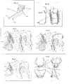
Fig 1-10 shows the upper tier embodiment and the steps to reach it that would typically be installed on the lower tier sleeper side wall. -
Fig 1-20 shows the lower tier sleeper. The embodiment shown has the modular structure with interlocking elements for strength. -
Fig 1-60 shows the modular elements interlocked.Fig 1-7F shows an embodiment with upper and lower sleepers -
Fig 1-80 ,1-80a ,1-90 ,1- 9Da ,1-100, 1-110 and1-11Da show another view of the embodiment. -
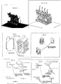
Fig 2-1 : Support structure for a single lower tier Airsleeper that functions as a module that can be interlocked with adjoining AirSleeper modules.
Considering the high moments that are experienced during axial deceleration under crash loading conditions, the embodiment shows flanges and support surfaces that will interlock with the adjoining modules to prevent reorientation of the modules by countering the moments. -
Fig 2-2 : Shows a the support structure for an AirSleeper module with an embodiment of arrangements to provide resistance to the axial crash loadings. Here the structure used for seperatoing the leg area of the upper tier from the lower tier occupant and the step structure are used to brace the module structure of the lower tier Airsleeper by providing a shear plane.
The shear plane may be extended further to the further sided of the AirSleeper module but will in that situation reduce the egress and ingress comfort of the occupant. The actual step structure may also have a rear wall that can provide an additional shear plane. -
Fig 2-8 : shows an embodiment of a foot frame for the Air Sleeper with arrangements to accommodate the torque or moment during axial loadings of a crash loading. The ledges shown counter the moments between the foot frames and equalize the loading as a result without transferring these forces directly to the tracks. Morevoer, the figure shows arrangements for equalizing the loads between the latches attached to the tracks. The elongated apertures with flexible and deformable inserts allow some deflection till the forces equalize between the latch points either during crash loadings or flexing of the airframe. -
Fig 2-11 : Shows the support module for the AirSleeper. Here the moments created by the axial crash loadings are equalized using latch arrangements that may in some cases be retracted so that it will allow individual Airsleeper modules to be removed without removing adjoining AirSleeper modules for maintenance purposes or for partial repopulating the cabin with new AirSleepers for market or maintenance reasons. - Background of the present invention includes seating arrangements that are tiered in vehicles. For example UK
Patent Application GB 2 350 828 Fig 2 ,Fig 3 Fig 4 illustrates seats that are placed adjoining each other in two tiers with access using common stairways for the upper tier occupants. The seats are oriented to be in the direction of the vehicle axis of motion alongside aisles for access. Moreover, the seats on the second tier are offset in the direction of the aisle (the facing direction of the occupants), with regard to the seats of the first tier. - The embodiment of the AirSleeper shown may be deployed at an angle to the axis of the aircraft. The design takes advantage of the longer and shorter sides of each of the sleepers to help with the ergonomics of the sleepers. For example the longer side is used to support the stairs to the upper tier and thereby gets the stairs as far away from the lower tier occupant as follows. The embodiment also gets the leg space of upper tier occupant to be adjoining the sidewall of the lower tier occupant space thereby giving a wider space for egress and ingress of the lower tier occupant targeting the shorter side of that occupant's sleeper.
- The Airsleepers are designed to be modular and in some of the embodiments have a dovetail structure as shown for added strength, creating among them a stiff honey comb structure that will be resilient to crash loadings substantially axially to the aircraft Egress and ingress is facilitated with a handle that is recessing into the wall of the modular housing.
- The upper tier in this embodiment is open and may have a support member of the monitor and the modular oxygen supply as shown for example in
Fig 1- 6 . - This embodiment may have static arm rests that are attached to the modular support structure. As shown in
Fig 1-12, 1-13 and 1-14 , the actuation by the pivotally supported linear actuator, pushes or pulls the pivot between the seat back and the seat bottom. The seat back is forced to move along an arc as it has a pivot tot eh fixed structure higher along its length. Therefore, the seat bottom end moves in an arc. The front of the seat bottom maybe attached to the fixed structure with a sliding mechanisms that may be designed to give the seat bottom the preferred inclination to
the seat back at different postures. therefore the slide guide or slot may be a curved to achieve this . - The leg rest in this embodiment retracts under the seat bottom. It may be actuated by a separate manual or electric actuator, or an extension the actuator driving the seat position, by using limit switches to activate latches that allow the head of the actuator to move along the seat bottom once it has paused the seat to a horizontal position and it ash been locked in that place following the action of limit switches.
- The seat back has a novel support structure that is shaped to accommodate the bending stresses during a crash loading.
- The orientation of the occupant will be facing slightly backwards at some angle and so the long side of the seat back will be the impact side and will therefore have the head of the occupant closer to this side that will benefit the occupant with regard to safety.
- The embodiments do not show the foot frame or support elements that support the Air sleepers. These are the subject of prior applications.
- The AirSleeper is an accommodation for passengers in aircraft that allows deployment as a tiered bed and in most embodiments a seat as well. The Air Sleeper may be implemented in a modular fashion and each passenger has a module that has a structure that locks to the adjoining similar AirSleeper structures and the support frame below, thereby creating a rigid honeycomb like structure to resist loading along the axis of the aircraft.
- Considering that the upper tier of AirSleeper modules are supported by the lower tier and locked thereto {directly or with load limiters), the loading on the lower AirSleepers need to accommodate a high moment due to crash load forces on the upper tier. Additional features for the lower tier Air Sleeper modules are presented herewith. The features shown in
Fig 2-1, 2-2 ,2-8 and2-11 , addresses some of the enhancements to further support the structure under such loading conditions.Fig 2-1 shows the AirSleeper structural module with ledges or flanges (that may be retractable in some embodiments) such that the flanges on the rear side of the AirSleeper with regard to the motion of the aircraft face upwards to support a downward force from the adjoining AirSleeper support module and the flanges on the front side of each of the Air Sleeper modules face downwards to support an upward force from the adjoining AirSleeper module. These forces will be the result of each of the AirSleeper structure modules attempting to rotate about their supports below towards the front of the aircraft as a result of the crash load. Normally for separate seats this will result in a tensile load at the rear seat track support point and a compressive load at the front seat track support point. The invention however, equalizes these forces within the AirSleeper module structure and only the residual load is transferred to the seat tracks. -
Fig 2-11 shows latches that may be retracted for the same purpose. Notably retraction of such latches will enable the removal of one or more of the AirSleepers for maintenance or reconfiguration without removing the entire Bank of Air Sleepers in a locked row. The latches can use techniques for locking and retraction well disclosed in the background art -
Fig 2-2 shows an enhancement for improving the structural rigidity of the AirSleeper during crash loadings by creating a shear plane with the feature that separates the leg area of the upper tier from the lower occupant space. This feature may be connected on its side and top to the lower tier AirSleeper structure to perform this function. The connection may be extended to the further side of the AirSleeper to increase such rigidity further. - Moreover, this feature may be connected to the steps that enable egress and ingress for the occupant in the upper tier of the Air Sleeper, thereby further increasing the rigidity under crash loading conditions for each of the AirSleeper modules. Some embodiments may have a rear wall for the steps that can increase the shear plane further down to further increase the rigidity offered.
-
Fig 2-8 Provides yet another features for addressing the crash loading conditions. The ledges shown on the rear of each foot frame, will provide upward forces on the adjoining foot frame and the ledges shown on the front of each foot frame provides a downward force on the adjoining foot frame, these forces thereby neutralizing each other in an array of such foot frames assembled end to end and as a result reducing the forces on the tracks to the residual force. The surface of the contact points of the foot frames to each other may have a compressible material thereby creating some force equalization between the foot frames to accommodate engineering inaccuracies. - Another feature shown in this figure is useful for AirSleeper structure modules that may be of different widths and therefore may require support points that accommodate varying spacing requirements. The support points are spaced to accommodate multiple standard widths of Ari Sleeper. Many embodiments will use load limiters between the Foot frames and the AirSleeper modules.
- Yet another feature in
Fig 2-8 , is the elongated support points for latches to the seat tracks. Such elongated support points may house flexible or compressible material surrounding the eye that is attached to the support point. Such flexibility enabled with such an arrangement or any other load limiting arrangement well disclosed in the background art will allow for load equalization across the latch points in the event of a crash loading condition or in the event of flexing of the Air frameFig. 2-3, 2-4 ,2-5, 2-6, 2-7, 2-9 ,2-9A ,3-1, 3-2, 3-3 and 3-4 do not fall under the scope of protction - It will become apparent that the present invention presented, provides a new paradigm for implementing key safety features Comfort and convenience features for occupants in vehicles.
Claims (11)
- A system of modular vehicle occupant supports[Figs 1-7D, 1-8D, 1-8Da, 1-9D, 1-9Da, 1-10D, 1-11D, 1-11Da], wherein said modular occupant supports are in two or more tiers and wherein each tier comprises a plurality of modular occupant supports, and wherein the modular occupant supports in the second tier are offset with regard to the modular occupant supports in the first tier, and wherein the first tier of modular occupant support have direct egress and ingress access to occupants, and wherein egress and ingress to each of the modular occupant supports in the second tier requires a means for elevating the occupant, and wherein means for such elevation for each of said modular occupant supports on the second tier is a set of stairs [101],
characterized by:- said offset of said second tier occupant supports with regard to the first tier occupant supports is lateral with regard to the facing direction of the occupant supports [Figs 1-6D, Fig 1-7D, 1-8D, 1-8Da, 1-9D, 1-9Da, 1-10D, 1-11D, 1-11Da];- said stairs being located along a side wall of one of said modular occupant supports on the first tier [Fig 2-2, 1-6D, Fig 1-7D, 1-8D, 1-8Da, 1-9D, 1-9Da, 1-10D, 1-11D, 1-11Da], thereby providing means for egress and ingress of an occupant in the second tier without limiting space egress and ingress of the occupant in the first tier, said limiting of space being determined by one of both of the extent of offset of the second tier relative to the first tier and the width of the stairs. - A system of modular vehicle occupant supports as in claim 1, wherein one or more of the set of stairs and the bottom of the modular occupant support on the second tier served by said set of stairs have attached there between a rear wall [Fig 2-2] that acts as a shear plane for bracing the modular occupant support as part of the system of modular occupant supports in the event of a substantially lateral loading.
- A system of modular vehicle occupant supports as in claim 1, wherein at least one of said modular vehicle occupant supports has an occupant facing direction, and comprises a seat back [104] with a bottom edge and a seat bottom [119] with a front and a rear edge, wherein said seat back is connected pivotally [116] along its bottom edge to the rear edge of the seat bottom, and wherein said seat back is supported pivotally [113] at a predetermined distance from its lower edge, and said seat bottom is supported at a predetermined distance from its front edge by one or more sliding surfaces [117, 118] enabled to slide along a surface on the support structure of the modular occupant support, such that as the seat back pivots about its support from a sitting position to a flat bed position, the sliding surface of the seat bottom follows a trajectory defined by the sliding surface on the support structure such that at each angle of orientation of the seat back the height of the sliding surface on the seat bottom may be predefined and thereby the angle of the seat bottom may be controlled for the comfort of the passenger.
- A system of modular vehicle occupant supports as in claim 3, wherein at least one of said modular vehicle occupant supports further comprises a retractable leg rest [120], retractable into the seat bottom, and where in an actuator [107] is enabled to move the pivot point of the seat back and bottom about an arc from the sitting position to the flat bed position and thereafter, following the activation of one or more limit switched at a predetermined angle of the seat back, pushes said foot rest out of the seat bottom, thereby creating a single mechanism for the actuation of the modular occupant support .
- A system of modular vehicle occupant supports as In claim 4, wherein at least one of said modular vehicle occupant supports comprises multiple limit switches to enable the actuation of the leg rest at different inclinations of the seat back.
- A system of modular vehicle occupant supports as in claim 1, wherein said modular occupant supports are inclined to the lateral direction of the vehicle [Fig1-9D], and thereby a front of a first side of each of the modular vehicle occupant supports is longer than a front of a second side, and wherein the stairs are located on the first side thereby one or both of increasing the space available behind the stairs for a lower tier occupant and easing egress and ingress for the lower tier occupant.
- A system of modular vehicle occupant supports as in claim 1, wherein said modular occupant supports are inclined to the lateral direction of the vehicle, and thereby a rear of a first side of each of the modular vehicle occupant supports is shorter than a rear of a second side and wherein the direction of motion of the vehicle is from the first side to the second side, said seat back further comprising a substantially vertical surface [108] on the second side of the seat back to support the occupant in the event of a rapid deceleration of the vehicle.
- A system of modular vehicle occupant supports as in claim 1, wherein said modular occupant supports are inclined to the lateral direction of the vehicle, and thereby a rear of a first side of each of the modular vehicle occupant supports is shorter than a rear of a second side and wherein the direction of motion of the vehicle is from the second side to the first side, and further comprising a support structure [108] that is curved in the direction of the front of the vehicle to accommodate loadings in the event of a rapid deceleration of the vehicle.
- A system of modular vehicle occupant supports as in claim 1, wherein said first tier of modular occupant supports are supported by an array of foot frames, wherein said foot frames are locked to seat tracks of the vehicle with support linkages comprising spring damper properties to reduce the spikes in inertial loading upon rapid deceleration of the vehicle.
- A system of modular vehicle occupant supports as in claim 1, wherein the modular occupant supports are supported by adjoining modular occupant supports with flanges [Fig 2-1] that transfer torsional loadings during rapid deceleration of the vehicle, thereby neutralizing the compressive loading at the front and the tensile loading at the back of each modular occupant support thereby minimizing the net restraining force required by the support structure for said system of modular occupant supports during rapid deceleration of the vehicle, and wherein said flanges may be retracted for removal and reinstallation of said modular vehicle occupant supports.
- A system of modular vehicle occupant supports as in claim 1, wherein the occupant supports in the second tier comprise one or both of an integrated oxygen system support and a video screen support for the occupant on an elevated stalk [Figs 1-3,1-4].
Applications Claiming Priority (7)
| Application Number | Priority Date | Filing Date | Title |
|---|---|---|---|
| US40275110P | 2010-09-03 | 2010-09-03 | |
| US40433510P | 2010-10-01 | 2010-10-01 | |
| US45899710P | 2010-12-03 | 2010-12-03 | |
| US45969810P | 2010-12-16 | 2010-12-16 | |
| US201061460266P | 2010-12-29 | 2010-12-29 | |
| US201161465160P | 2011-03-15 | 2011-03-15 | |
| PCT/US2011/001547 WO2012030401A2 (en) | 2010-09-03 | 2011-09-06 | Vehicle occupant support |
Publications (2)
| Publication Number | Publication Date |
|---|---|
| EP2632763A2 EP2632763A2 (en) | 2013-09-04 |
| EP2632763B1 true EP2632763B1 (en) | 2021-06-23 |
Family
ID=44678017
Family Applications (1)
| Application Number | Title | Priority Date | Filing Date |
|---|---|---|---|
| EP11761169.9A Active EP2632763B1 (en) | 2010-09-03 | 2011-09-06 | Vehicle occupant support |
Country Status (5)
| Country | Link |
|---|---|
| US (1) | US9358908B2 (en) |
| EP (1) | EP2632763B1 (en) |
| JP (2) | JP2013536784A (en) |
| CN (2) | CN103249593B (en) |
| WO (1) | WO2012030401A2 (en) |
Families Citing this family (12)
| Publication number | Priority date | Publication date | Assignee | Title |
|---|---|---|---|---|
| USRE47872E1 (en) | 2011-07-11 | 2020-02-25 | Molon Labe Llc | Slider seat for aircraft |
| US10150392B2 (en) * | 2016-02-24 | 2018-12-11 | Ayyakannu Mani | Combat vehicle seat installation for protection of occupants from the effects of ground explosions |
| DE102016219105A1 (en) | 2016-09-30 | 2018-04-05 | Brose Fahrzeugteile Gmbh & Co. Kg, Coburg | Adjusting device with spindle drive for a seat element of a vehicle seat |
| US10569881B2 (en) | 2016-10-18 | 2020-02-25 | Molon Labe, Llc | Staggered aircraft seat assembly |
| US10315539B2 (en) | 2017-05-09 | 2019-06-11 | Dorel Juvenile Group, Inc. | Child restraint with vehicle seatbelt management system |
| USD840701S1 (en) | 2017-10-18 | 2019-02-19 | Molon Labe, Llc | Staggered aircraft seats |
| USD850177S1 (en) | 2017-12-15 | 2019-06-04 | Molon Labe, Llc | Aircraft seat armrests |
| USD867775S1 (en) | 2018-04-03 | 2019-11-26 | Molon Labe, Llc | Set of multilevel aircraft seat armrests |
| CN109017463B (en) * | 2018-06-21 | 2020-09-01 | 董礼利 | Adjustable backrest suitable for seat |
| USD936383S1 (en) | 2019-08-01 | 2021-11-23 | Molon Labe, Llc | Staggered aircraft seat assembly |
| USD924043S1 (en) | 2019-08-22 | 2021-07-06 | Molon Labe, Llc | Aircraft wheelchair accommodating seat assembly |
| US20210298368A1 (en) * | 2020-03-30 | 2021-09-30 | Pocco Scott David Deaundrea Bussey | Hooded pull-over garment with detachable reusable and interchangeable face mask |
Family Cites Families (20)
| Publication number | Priority date | Publication date | Assignee | Title |
|---|---|---|---|---|
| GB9103841D0 (en) * | 1991-02-23 | 1991-04-10 | Britax Roemer Kindersicherheit Gmbh | Shock absorber for vehicle seat belt |
| JPH09136564A (en) * | 1995-11-14 | 1997-05-27 | Riiman Kk | Child seat |
| US5884967A (en) * | 1997-04-17 | 1999-03-23 | Gasper; Ronald | Child vehicle safety seat |
| JPH11321407A (en) * | 1998-05-08 | 1999-11-24 | Toyota Motor Corp | Child seat fitting structure |
| GB2350828A (en) * | 1999-06-05 | 2000-12-13 | Dca Design Int Ltd | Passenger railway vehicle |
| WO2009079668A2 (en) * | 2007-12-17 | 2009-06-25 | Rajasingham Arjuna Indraeswara | Vehicle occupant support |
| US6394241B1 (en) * | 1999-10-21 | 2002-05-28 | Simula, Inc. | Energy absorbing shear strip bender |
| JP2004509017A (en) * | 2000-09-19 | 2004-03-25 | マクドネル、ウィリアム・アール | Seat to convert into a couch |
| JP4902070B2 (en) * | 2001-08-22 | 2012-03-21 | コンビ株式会社 | child seat |
| KR20040104993A (en) * | 2003-06-03 | 2004-12-14 | 현대자동차주식회사 | active headrest |
| US7607697B2 (en) * | 2003-06-18 | 2009-10-27 | Indiana Mills & Manufacturing, Inc. | Load control device |
| JP2005112054A (en) * | 2003-10-03 | 2005-04-28 | Aprica Kassai Inc | Neck position holder |
| KR100901926B1 (en) * | 2004-01-30 | 2009-06-10 | 도요다 보쇼꾸 가부시키가이샤 | Head rest control device |
| US7293740B2 (en) * | 2004-07-27 | 2007-11-13 | The Boeing Company | Aircraft crewmember articulating berth system |
| DE102004062219B4 (en) * | 2004-12-23 | 2008-12-24 | Schukra Gerätebau AG | Seat element and seating system |
| US7658444B2 (en) * | 2006-12-08 | 2010-02-09 | Ford Global Technologies, Llc | Energy absorbing seat anchor restraint system for child safety seats |
| CN101234641A (en) * | 2007-01-29 | 2008-08-06 | 于君 | Three-layer type sleeping cabin |
| US7699393B2 (en) * | 2007-10-03 | 2010-04-20 | Evenflo Company Inc. | Load limiting (energy management) child restraint seat |
| DE102009017601B4 (en) * | 2009-04-16 | 2011-06-22 | RECARO GmbH & Co. KG, 73230 | Child car seat |
| US8226162B2 (en) * | 2009-09-11 | 2012-07-24 | Campbell Corey A | Child safety seat |
-
2011
- 2011-09-06 US US13/820,510 patent/US9358908B2/en active Active
- 2011-09-06 CN CN201180058999.XA patent/CN103249593B/en not_active Expired - Fee Related
- 2011-09-06 CN CN201610051802.4A patent/CN105882977A/en active Pending
- 2011-09-06 WO PCT/US2011/001547 patent/WO2012030401A2/en active Application Filing
- 2011-09-06 JP JP2013527067A patent/JP2013536784A/en active Pending
- 2011-09-06 EP EP11761169.9A patent/EP2632763B1/en active Active
-
2016
- 2016-07-26 JP JP2016146641A patent/JP2017019495A/en active Pending
Non-Patent Citations (1)
| Title |
|---|
| None * |
Also Published As
| Publication number | Publication date |
|---|---|
| US9358908B2 (en) | 2016-06-07 |
| WO2012030401A2 (en) | 2012-03-08 |
| CN103249593A (en) | 2013-08-14 |
| JP2013536784A (en) | 2013-09-26 |
| US20130193726A1 (en) | 2013-08-01 |
| JP2017019495A (en) | 2017-01-26 |
| EP2632763A2 (en) | 2013-09-04 |
| WO2012030401A3 (en) | 2012-07-26 |
| CN103249593B (en) | 2016-03-02 |
| CN105882977A (en) | 2016-08-24 |
| WO2012030401A8 (en) | 2013-05-16 |
Similar Documents
| Publication | Publication Date | Title |
|---|---|---|
| EP2632763B1 (en) | Vehicle occupant support | |
| EP3312090B1 (en) | Passenger seating with partition assembly | |
| US7726607B2 (en) | Flight passenger seat with an integrated spring element | |
| EP2981469B1 (en) | Vertically stowed tray table assembly with translational movement | |
| US8226163B1 (en) | Aircraft divan | |
| EP3060472B1 (en) | Linearly deployable aircraft seat legrest | |
| US10173779B2 (en) | Vehicle occupant support | |
| US20140167461A1 (en) | Secure herringbone arrangement for the armrest of a seat, seat and two seat assembly provided with such an arrangement | |
| EP3277583B1 (en) | Adjustable headrest enabling sideward leaning and seclusion | |
| US9463725B2 (en) | Comfort headrest | |
| EP3129290B1 (en) | Seat unit limiting the risk of head injuries | |
| JP2013536784A5 (en) | ||
| US9120574B2 (en) | Passenger seat | |
| CN106255640A (en) | There is to adjust the aircraft seat of the drive and passengers weight sensing mechanism of tilt tilting force | |
| US20130200676A1 (en) | Vehicle seat | |
| US10556523B1 (en) | Vehicle occupant support | |
| EP3019402B1 (en) | Vehicle occupant support | |
| EP2444276A1 (en) | Vehicle seat | |
| US11945590B1 (en) | Aircraft seat with energy attenuating metering plate | |
| US20240083583A1 (en) | Aircraft bulkhead-mounted pilot seat with horizontal and vertical adjustment | |
| DE102012012261A1 (en) | Aircraft passenger seat device, has armrest unit to be supported at seat back unit or seat bottom unit and provided to two airplane seats that are arranged next to each other and mounted to seat back frame |
Legal Events
| Date | Code | Title | Description |
|---|---|---|---|
| PUAI | Public reference made under article 153(3) epc to a published international application that has entered the european phase |
Free format text: ORIGINAL CODE: 0009012 |
|
| 17P | Request for examination filed |
Effective date: 20130307 |
|
| AK | Designated contracting states |
Kind code of ref document: A2 Designated state(s): AL AT BE BG CH CY CZ DE DK EE ES FI FR GB GR HR HU IE IS IT LI LT LU LV MC MK MT NL NO PL PT RO RS SE SI SK SM TR |
|
| DAX | Request for extension of the european patent (deleted) | ||
| RAP1 | Party data changed (applicant data changed or rights of an application transferred) |
Owner name: RAJASINGHAM, ARJUNA I. |
|
| RIN1 | Information on inventor provided before grant (corrected) |
Inventor name: RAJASINGHAM, ARJUNA I. |
|
| RAP1 | Party data changed (applicant data changed or rights of an application transferred) |
Owner name: RAJASINGHAM, ARJUNA, INDRAESWARAN |
|
| RIN1 | Information on inventor provided before grant (corrected) |
Inventor name: RAJASINGHAM, ARJUNA, INDRAESWARAN |
|
| STAA | Information on the status of an ep patent application or granted ep patent |
Free format text: STATUS: EXAMINATION IS IN PROGRESS |
|
| 17Q | First examination report despatched |
Effective date: 20171009 |
|
| RAP1 | Party data changed (applicant data changed or rights of an application transferred) |
Owner name: RAJASINGHAM, ARJUNA, INDRAESWARAN |
|
| RIN1 | Information on inventor provided before grant (corrected) |
Inventor name: RAJASINGHAM, ARJUNA, INDRAESWARAN |
|
| GRAP | Despatch of communication of intention to grant a patent |
Free format text: ORIGINAL CODE: EPIDOSNIGR1 |
|
| STAA | Information on the status of an ep patent application or granted ep patent |
Free format text: STATUS: GRANT OF PATENT IS INTENDED |
|
| INTG | Intention to grant announced |
Effective date: 20210115 |
|
| GRAS | Grant fee paid |
Free format text: ORIGINAL CODE: EPIDOSNIGR3 |
|
| GRAA | (expected) grant |
Free format text: ORIGINAL CODE: 0009210 |
|
| STAA | Information on the status of an ep patent application or granted ep patent |
Free format text: STATUS: THE PATENT HAS BEEN GRANTED |
|
| AK | Designated contracting states |
Kind code of ref document: B1 Designated state(s): AL AT BE BG CH CY CZ DE DK EE ES FI FR GB GR HR HU IE IS IT LI LT LU LV MC MK MT NL NO PL PT RO RS SE SI SK SM TR |
|
| REG | Reference to a national code |
Ref country code: GB Ref legal event code: FG4D |
|
| REG | Reference to a national code |
Ref country code: CH Ref legal event code: EP |
|
| REG | Reference to a national code |
Ref country code: DE Ref legal event code: R096 Ref document number: 602011071216 Country of ref document: DE Ref country code: AT Ref legal event code: REF Ref document number: 1404039 Country of ref document: AT Kind code of ref document: T Effective date: 20210715 |
|
| REG | Reference to a national code |
Ref country code: IE Ref legal event code: FG4D |
|
| REG | Reference to a national code |
Ref country code: LT Ref legal event code: MG9D |
|
| PG25 | Lapsed in a contracting state [announced via postgrant information from national office to epo] |
Ref country code: BG Free format text: LAPSE BECAUSE OF FAILURE TO SUBMIT A TRANSLATION OF THE DESCRIPTION OR TO PAY THE FEE WITHIN THE PRESCRIBED TIME-LIMIT Effective date: 20210923 Ref country code: HR Free format text: LAPSE BECAUSE OF FAILURE TO SUBMIT A TRANSLATION OF THE DESCRIPTION OR TO PAY THE FEE WITHIN THE PRESCRIBED TIME-LIMIT Effective date: 20210623 Ref country code: LT Free format text: LAPSE BECAUSE OF FAILURE TO SUBMIT A TRANSLATION OF THE DESCRIPTION OR TO PAY THE FEE WITHIN THE PRESCRIBED TIME-LIMIT Effective date: 20210623 Ref country code: FI Free format text: LAPSE BECAUSE OF FAILURE TO SUBMIT A TRANSLATION OF THE DESCRIPTION OR TO PAY THE FEE WITHIN THE PRESCRIBED TIME-LIMIT Effective date: 20210623 |
|
| REG | Reference to a national code |
Ref country code: DE Ref legal event code: R084 Ref document number: 602011071216 Country of ref document: DE |
|
| REG | Reference to a national code |
Ref country code: AT Ref legal event code: MK05 Ref document number: 1404039 Country of ref document: AT Kind code of ref document: T Effective date: 20210623 |
|
| PG25 | Lapsed in a contracting state [announced via postgrant information from national office to epo] |
Ref country code: GR Free format text: LAPSE BECAUSE OF FAILURE TO SUBMIT A TRANSLATION OF THE DESCRIPTION OR TO PAY THE FEE WITHIN THE PRESCRIBED TIME-LIMIT Effective date: 20210924 Ref country code: LV Free format text: LAPSE BECAUSE OF FAILURE TO SUBMIT A TRANSLATION OF THE DESCRIPTION OR TO PAY THE FEE WITHIN THE PRESCRIBED TIME-LIMIT Effective date: 20210623 Ref country code: RS Free format text: LAPSE BECAUSE OF FAILURE TO SUBMIT A TRANSLATION OF THE DESCRIPTION OR TO PAY THE FEE WITHIN THE PRESCRIBED TIME-LIMIT Effective date: 20210623 Ref country code: SE Free format text: LAPSE BECAUSE OF FAILURE TO SUBMIT A TRANSLATION OF THE DESCRIPTION OR TO PAY THE FEE WITHIN THE PRESCRIBED TIME-LIMIT Effective date: 20210623 Ref country code: NO Free format text: LAPSE BECAUSE OF FAILURE TO SUBMIT A TRANSLATION OF THE DESCRIPTION OR TO PAY THE FEE WITHIN THE PRESCRIBED TIME-LIMIT Effective date: 20210923 |
|
| REG | Reference to a national code |
Ref country code: NL Ref legal event code: MP Effective date: 20210623 |
|
| PG25 | Lapsed in a contracting state [announced via postgrant information from national office to epo] |
Ref country code: SM Free format text: LAPSE BECAUSE OF FAILURE TO SUBMIT A TRANSLATION OF THE DESCRIPTION OR TO PAY THE FEE WITHIN THE PRESCRIBED TIME-LIMIT Effective date: 20210623 Ref country code: SK Free format text: LAPSE BECAUSE OF FAILURE TO SUBMIT A TRANSLATION OF THE DESCRIPTION OR TO PAY THE FEE WITHIN THE PRESCRIBED TIME-LIMIT Effective date: 20210623 Ref country code: EE Free format text: LAPSE BECAUSE OF FAILURE TO SUBMIT A TRANSLATION OF THE DESCRIPTION OR TO PAY THE FEE WITHIN THE PRESCRIBED TIME-LIMIT Effective date: 20210623 Ref country code: CZ Free format text: LAPSE BECAUSE OF FAILURE TO SUBMIT A TRANSLATION OF THE DESCRIPTION OR TO PAY THE FEE WITHIN THE PRESCRIBED TIME-LIMIT Effective date: 20210623 Ref country code: RO Free format text: LAPSE BECAUSE OF FAILURE TO SUBMIT A TRANSLATION OF THE DESCRIPTION OR TO PAY THE FEE WITHIN THE PRESCRIBED TIME-LIMIT Effective date: 20210623 Ref country code: NL Free format text: LAPSE BECAUSE OF FAILURE TO SUBMIT A TRANSLATION OF THE DESCRIPTION OR TO PAY THE FEE WITHIN THE PRESCRIBED TIME-LIMIT Effective date: 20210623 Ref country code: PT Free format text: LAPSE BECAUSE OF FAILURE TO SUBMIT A TRANSLATION OF THE DESCRIPTION OR TO PAY THE FEE WITHIN THE PRESCRIBED TIME-LIMIT Effective date: 20211025 Ref country code: ES Free format text: LAPSE BECAUSE OF FAILURE TO SUBMIT A TRANSLATION OF THE DESCRIPTION OR TO PAY THE FEE WITHIN THE PRESCRIBED TIME-LIMIT Effective date: 20210623 Ref country code: AT Free format text: LAPSE BECAUSE OF FAILURE TO SUBMIT A TRANSLATION OF THE DESCRIPTION OR TO PAY THE FEE WITHIN THE PRESCRIBED TIME-LIMIT Effective date: 20210623 |
|
| PG25 | Lapsed in a contracting state [announced via postgrant information from national office to epo] |
Ref country code: PL Free format text: LAPSE BECAUSE OF FAILURE TO SUBMIT A TRANSLATION OF THE DESCRIPTION OR TO PAY THE FEE WITHIN THE PRESCRIBED TIME-LIMIT Effective date: 20210623 |
|
| REG | Reference to a national code |
Ref country code: DE Ref legal event code: R097 Ref document number: 602011071216 Country of ref document: DE |
|
| PG25 | Lapsed in a contracting state [announced via postgrant information from national office to epo] |
Ref country code: DK Free format text: LAPSE BECAUSE OF FAILURE TO SUBMIT A TRANSLATION OF THE DESCRIPTION OR TO PAY THE FEE WITHIN THE PRESCRIBED TIME-LIMIT Effective date: 20210623 |
|
| PLBE | No opposition filed within time limit |
Free format text: ORIGINAL CODE: 0009261 |
|
| STAA | Information on the status of an ep patent application or granted ep patent |
Free format text: STATUS: NO OPPOSITION FILED WITHIN TIME LIMIT |
|
| REG | Reference to a national code |
Ref country code: CH Ref legal event code: PL |
|
| REG | Reference to a national code |
Ref country code: BE Ref legal event code: MM Effective date: 20210930 |
|
| 26N | No opposition filed |
Effective date: 20220324 |
|
| PG25 | Lapsed in a contracting state [announced via postgrant information from national office to epo] |
Ref country code: MC Free format text: LAPSE BECAUSE OF FAILURE TO SUBMIT A TRANSLATION OF THE DESCRIPTION OR TO PAY THE FEE WITHIN THE PRESCRIBED TIME-LIMIT Effective date: 20210623 Ref country code: AL Free format text: LAPSE BECAUSE OF FAILURE TO SUBMIT A TRANSLATION OF THE DESCRIPTION OR TO PAY THE FEE WITHIN THE PRESCRIBED TIME-LIMIT Effective date: 20210623 |
|
| PG25 | Lapsed in a contracting state [announced via postgrant information from national office to epo] |
Ref country code: LU Free format text: LAPSE BECAUSE OF NON-PAYMENT OF DUE FEES Effective date: 20210906 Ref country code: IT Free format text: LAPSE BECAUSE OF FAILURE TO SUBMIT A TRANSLATION OF THE DESCRIPTION OR TO PAY THE FEE WITHIN THE PRESCRIBED TIME-LIMIT Effective date: 20210623 Ref country code: IE Free format text: LAPSE BECAUSE OF NON-PAYMENT OF DUE FEES Effective date: 20210906 Ref country code: BE Free format text: LAPSE BECAUSE OF NON-PAYMENT OF DUE FEES Effective date: 20210930 |
|
| PG25 | Lapsed in a contracting state [announced via postgrant information from national office to epo] |
Ref country code: LI Free format text: LAPSE BECAUSE OF NON-PAYMENT OF DUE FEES Effective date: 20210930 Ref country code: CH Free format text: LAPSE BECAUSE OF NON-PAYMENT OF DUE FEES Effective date: 20210930 |
|
| PGFP | Annual fee paid to national office [announced via postgrant information from national office to epo] |
Ref country code: GB Payment date: 20220926 Year of fee payment: 12 Ref country code: DE Payment date: 20220927 Year of fee payment: 12 |
|
| PGFP | Annual fee paid to national office [announced via postgrant information from national office to epo] |
Ref country code: FR Payment date: 20220926 Year of fee payment: 12 |
|
| PG25 | Lapsed in a contracting state [announced via postgrant information from national office to epo] |
Ref country code: HU Free format text: LAPSE BECAUSE OF FAILURE TO SUBMIT A TRANSLATION OF THE DESCRIPTION OR TO PAY THE FEE WITHIN THE PRESCRIBED TIME-LIMIT; INVALID AB INITIO Effective date: 20110906 Ref country code: CY Free format text: LAPSE BECAUSE OF FAILURE TO SUBMIT A TRANSLATION OF THE DESCRIPTION OR TO PAY THE FEE WITHIN THE PRESCRIBED TIME-LIMIT Effective date: 20210623 |
|
| PGFP | Annual fee paid to national office [announced via postgrant information from national office to epo] |
Ref country code: DE Payment date: 20221025 Year of fee payment: 12 |