EP2632545B1 - An external controller for an implantable medical device formed using a sub-assembly - Google Patents
An external controller for an implantable medical device formed using a sub-assembly Download PDFInfo
- Publication number
- EP2632545B1 EP2632545B1 EP11770026.0A EP11770026A EP2632545B1 EP 2632545 B1 EP2632545 B1 EP 2632545B1 EP 11770026 A EP11770026 A EP 11770026A EP 2632545 B1 EP2632545 B1 EP 2632545B1
- Authority
- EP
- European Patent Office
- Prior art keywords
- chassis
- external controller
- telemetry coil
- battery
- pcb
- Prior art date
- Legal status (The legal status is an assumption and is not a legal conclusion. Google has not performed a legal analysis and makes no representation as to the accuracy of the status listed.)
- Active
Links
- 229910000859 α-Fe Inorganic materials 0.000 claims description 21
- 238000004519 manufacturing process Methods 0.000 claims description 17
- 230000008878 coupling Effects 0.000 claims description 6
- 238000010168 coupling process Methods 0.000 claims description 6
- 238000005859 coupling reaction Methods 0.000 claims description 6
- 239000004593 Epoxy Substances 0.000 claims description 5
- 238000000034 method Methods 0.000 claims description 5
- 239000000853 adhesive Substances 0.000 claims description 3
- 230000001070 adhesive effect Effects 0.000 claims description 3
- ZLGYJAIAVPVCNF-UHFFFAOYSA-N 1,2,4-trichloro-5-(3,5-dichlorophenyl)benzene Chemical compound ClC1=CC(Cl)=CC(C=2C(=CC(Cl)=C(Cl)C=2)Cl)=C1 ZLGYJAIAVPVCNF-UHFFFAOYSA-N 0.000 description 17
- 230000000638 stimulation Effects 0.000 description 7
- 238000013461 design Methods 0.000 description 6
- 230000006870 function Effects 0.000 description 6
- 230000008901 benefit Effects 0.000 description 5
- 238000004891 communication Methods 0.000 description 5
- 238000007373 indentation Methods 0.000 description 5
- 210000000278 spinal cord Anatomy 0.000 description 4
- 230000005540 biological transmission Effects 0.000 description 3
- 238000005476 soldering Methods 0.000 description 3
- 238000004804 winding Methods 0.000 description 3
- 208000002193 Pain Diseases 0.000 description 2
- 210000004556 brain Anatomy 0.000 description 2
- 230000001054 cortical effect Effects 0.000 description 2
- 208000016354 hearing loss disease Diseases 0.000 description 2
- 230000001939 inductive effect Effects 0.000 description 2
- 230000001537 neural effect Effects 0.000 description 2
- 230000002207 retinal effect Effects 0.000 description 2
- 238000012360 testing method Methods 0.000 description 2
- 238000002560 therapeutic procedure Methods 0.000 description 2
- 210000001519 tissue Anatomy 0.000 description 2
- XVIZMMSINIOIQP-UHFFFAOYSA-N 1,2-dichloro-3-(2-chlorophenyl)benzene Chemical compound ClC1=CC=CC(C=2C(=CC=CC=2)Cl)=C1Cl XVIZMMSINIOIQP-UHFFFAOYSA-N 0.000 description 1
- 201000004569 Blindness Diseases 0.000 description 1
- 208000000094 Chronic Pain Diseases 0.000 description 1
- 206010011878 Deafness Diseases 0.000 description 1
- WHXSMMKQMYFTQS-UHFFFAOYSA-N Lithium Chemical compound [Li] WHXSMMKQMYFTQS-UHFFFAOYSA-N 0.000 description 1
- 208000019430 Motor disease Diseases 0.000 description 1
- 229910003962 NiZn Inorganic materials 0.000 description 1
- RTAQQCXQSZGOHL-UHFFFAOYSA-N Titanium Chemical compound [Ti] RTAQQCXQSZGOHL-UHFFFAOYSA-N 0.000 description 1
- 206010046543 Urinary incontinence Diseases 0.000 description 1
- 206010003119 arrhythmia Diseases 0.000 description 1
- 239000003990 capacitor Substances 0.000 description 1
- 206010061592 cardiac fibrillation Diseases 0.000 description 1
- 230000008859 change Effects 0.000 description 1
- 238000010276 construction Methods 0.000 description 1
- 231100000895 deafness Toxicity 0.000 description 1
- 230000003247 decreasing effect Effects 0.000 description 1
- 208000037265 diseases, disorders, signs and symptoms Diseases 0.000 description 1
- 208000035475 disorder Diseases 0.000 description 1
- 230000009977 dual effect Effects 0.000 description 1
- 230000005672 electromagnetic field Effects 0.000 description 1
- 238000005516 engineering process Methods 0.000 description 1
- 239000006260 foam Substances 0.000 description 1
- 229910052744 lithium Inorganic materials 0.000 description 1
- 229910001416 lithium ion Inorganic materials 0.000 description 1
- 238000012423 maintenance Methods 0.000 description 1
- 239000000463 material Substances 0.000 description 1
- 210000003205 muscle Anatomy 0.000 description 1
- 210000005036 nerve Anatomy 0.000 description 1
- 238000004806 packaging method and process Methods 0.000 description 1
- 230000035699 permeability Effects 0.000 description 1
- 230000010363 phase shift Effects 0.000 description 1
- 150000003071 polychlorinated biphenyls Chemical class 0.000 description 1
- 229920000642 polymer Polymers 0.000 description 1
- 208000020016 psychiatric disease Diseases 0.000 description 1
- 238000012552 review Methods 0.000 description 1
- 201000002859 sleep apnea Diseases 0.000 description 1
- 230000000087 stabilizing effect Effects 0.000 description 1
- 239000000758 substrate Substances 0.000 description 1
- 229910052719 titanium Inorganic materials 0.000 description 1
- 239000010936 titanium Substances 0.000 description 1
- 238000012546 transfer Methods 0.000 description 1
Images


Classifications
-
- A—HUMAN NECESSITIES
- A61—MEDICAL OR VETERINARY SCIENCE; HYGIENE
- A61N—ELECTROTHERAPY; MAGNETOTHERAPY; RADIATION THERAPY; ULTRASOUND THERAPY
- A61N1/00—Electrotherapy; Circuits therefor
- A61N1/18—Applying electric currents by contact electrodes
- A61N1/32—Applying electric currents by contact electrodes alternating or intermittent currents
- A61N1/36—Applying electric currents by contact electrodes alternating or intermittent currents for stimulation
- A61N1/372—Arrangements in connection with the implantation of stimulators
- A61N1/37211—Means for communicating with stimulators
- A61N1/37235—Aspects of the external programmer
-
- Y—GENERAL TAGGING OF NEW TECHNOLOGICAL DEVELOPMENTS; GENERAL TAGGING OF CROSS-SECTIONAL TECHNOLOGIES SPANNING OVER SEVERAL SECTIONS OF THE IPC; TECHNICAL SUBJECTS COVERED BY FORMER USPC CROSS-REFERENCE ART COLLECTIONS [XRACs] AND DIGESTS
- Y10—TECHNICAL SUBJECTS COVERED BY FORMER USPC
- Y10T—TECHNICAL SUBJECTS COVERED BY FORMER US CLASSIFICATION
- Y10T29/00—Metal working
- Y10T29/49—Method of mechanical manufacture
- Y10T29/49002—Electrical device making
- Y10T29/49016—Antenna or wave energy "plumbing" making
- Y10T29/49018—Antenna or wave energy "plumbing" making with other electrical component
Definitions
- the present invention relates to the design and packaging of an external telemetry device having particular applicability to implantable medical device systems.
- Implantable stimulation devices are devices that generate and deliver electrical stimuli to body nerves and tissues for the therapy of various biological disorders.
- Examples of such devices include pacemakers for treating cardiac arrhythmia, defibrillators for treating cardiac fibrillation, cochlear stimulators for treating deafness, retinal stimulators for treating blindness, muscle stimulators for producing coordinated limb movement, spinal cord stimulators for treating chronic pain, cortical and deep brain stimulators for treating motor and psychological disorders, and other neural stimulators for treating urinary incontinence, sleep apnea, shoulder sublaxation and the like.
- the present invention may find applicability in all such applications, although the description that follows will generally focus on the use of the invention within a Spinal Cord Stimulation (SCS) system, such as that disclosed in U.S. Patent 6,516,227 .
- SCS Spinal Cord Stimulation
- a SCS system typically includes an Implantable Pulse Generator (IPG) 100, which includes a biocompatible case 30 formed of titanium for example.
- the case 30 typically holds the circuitry and power source or battery necessary for the IPG to function, although IPGs can also be powered via external RF energy and without a battery.
- the IPG 100 is coupled to electrodes 106 via one or more electrode leads (two such leads 102 and 104 are shown), such that the electrodes 106 form an electrode array 110.
- the electrodes 106 are carried on a flexible body 108, which also houses the individual signal wires 112 and 114 coupled to each electrode.
- the number of leads and electrodes is application specific and therefore can vary.
- the IPG 100 typically includes an electronic substrate assembly 14 including a printed circuit board (PCB) 16, along with various electronic components 20, such as microprocessors, integrated circuits, and capacitors mounted to the PCB 16.
- PCB printed circuit board
- Two coils are generally present in the IPG 100, a telemetry coil 13 used to transmit/receive data to/from the external controller 12, and a charging coil 18 for charging or recharging the IPG's power source or battery 26 using an external charger (not shown).
- the telemetry coil 13 can be mounted within the header connector 36 as shown, or can be housed within the case 30.
- an external controller 12 such as a hand-held programmer or a clinician's programmer, is used to wirelessly send data to and receive data from the IPG 100.
- the external controller 12 can send programming data to the IPG 100 to set the therapy the IPG 100 will provide to the patient.
- the external controller 12 can act as a receiver of data from the IPG 100, such as various data reporting on the IPG's status.
- the communication of data to and from the external controller 12 occurs via magnetic inductive coupling.
- coil 17 is energized with an alternating current (AC).
- AC alternating current
- Such energizing of the coil 17 to transfer data can occur using a Frequency Shift Keying (FSK) protocol, for example, such as disclosed in U.S. Patent Application Publication 2009/0024179 .
- FSK Frequency Shift Keying
- Energizing the coil 17 induces an electromagnetic field, which in turn induces a current in the IPG's telemetry coil 13, which current can then be demodulated to recover the original data.
- Communication from the IPG 100 to the external controller 12 occurs in essentially the same way.
- inductive transmission of data or power occurs transcutaneously, i.e., through the patient's tissue 25, making it particularly useful in a medical implantable device system.
- External controller 210 disclosed in U.S. Patent Publication 2009/0118796 is shown in FIG. 3 (a different external controller is disclosed in WO 2008/014022 A1 ).
- This external controller 210 may integrate the functions of an external controller and an external charger that wirelessly provides power to the IPG's battery, but such battery charging aspects are not shown in FIG. 3 for simplicity.
- External controller 210 comprises a user interface, which is somewhat similar to a cell phone or to other external controllers used in the art, in that it includes a display 265 and various buttons 270. Soft key buttons 278 can be used to select various functions, which functions will vary depending on the status of the menu options available at any given time.
- a speaker is also included within the housing of the external controller to provide audio cues to the user (not shown).
- a vibration motor can provide feedback for users with hearing impairments or others who would like to turn the audio cues off.
- Unlock button 281 recessed into the side of the housing, can be used to unlock the buttons, if they become automatically or manually locked.
- External controller 210 also has a USB port 300, which can connect to a charging coil (as discussed in detail in the '796 Publication), to a computer, or to a power source (a wall outlet) to either power the external controller directly or to charge its battery 126 ( FIG. 4 ).
- the user interface generally allows the user to telemeter data (such as a new therapy program) from the external controller 210 to the IPG 100, or to monitor various forms of status feedback from the IPG.
- the software in the controller 210 (preferably implemented as microcode accessible by the controller 210's microcontroller) accordingly provides logical menu options to the display 265. For example, when the controller is first turned on, the display 265 may provide selectable options for the user to either program the IPG 100 or to change stimulation settings.
- the internal structure of external controller 210, with its cover 215 removed, is shown in FIG. 4 .
- a printed circuit board (PCB) 120 is central to the internal construction of the controller 210.
- the front side of the PCB 120 carries aspects of the user interface, including the display 265 and pressure-sensitive switches 122 for receiving presses to the various user interface buttons 270 ( FIG. 3 ).
- the external controller 210 controls data telemetry by energizing at least one coil 62a or 62b.
- the telemetry coils 62a and 62b and a battery 126 along with other integrated and discrete components necessary to implement the functionality of the external controller are located on the back side of the PCB 120.
- the battery 126 can comprise a Lithium (Li)-ion battery or a Li-ion polymer battery for example.
- the two telemetry coils 62a and 62b are respectively wrapped around axes 54a and 54b which are orthogonal.
- Coil 62a is wrapped in a racetrack configuration around the back of the PCB 120, while coil 62b is wrapped around a ferrite core 128.
- Further discussion of the benefits of orthogonally-oriented telemetry coils 62a and 62b can be found in U.S. Patent Publication 2009/0069869 , which with the reader is assumed familiar.
- the two coils 62a, 62b are driven (for example, with FSK-modulated data) out of phase, preferably at 90 degrees out of phase.
- the telemetry coils 62a and 62b are soldered to the PCB 120, and the coils 62a and 62b (including ferrite core 128 around which coil 62b is wound) must then be secured in place, usually by affixing them to the PCB using epoxy. These are cumbersome steps in the manufacturing process, and are prone to failure or reliability problems. Soldering and epoxying the coils 62a and 62b must be accomplished by hand, after the other various components 133 (a few of which are shown in FIG. 4 ) have already been surface mounted to the PCB 120. This risks damaging these other components 133.
- the ferrite core 128 can be easily damaged, should it be bumped during remaining steps in the manufacturing process.
- the external controller's battery 126 has similar manufacturing concerns. It too must be secured and soldered to the PCB 120 in some fashion, which can likewise damage the various components 133 previously surface mounted to the PCB. And like the coils 62a and 62b and the ferrite core 128, the battery 126 protrudes from the PCB 120 and is susceptible to damage.
- the mechanical design of the external controller 210 has another disadvantage in that the telemetry coils 62a and 62b, the ferrite core 128, and the battery 126 cover a large portion of the surface area of the back of PCB 120.
- the various other components 133 surface mounted to the PCB 120 should not be placed underneath such areas where the coils 62a and 62b, the ferrite core 128, and the battery 126 will be affixed, and thus space on the PCB 120 must be reserved for these additional structures. Reserving space on the PCB 120 for these additional structures limits where the other components 133 can be surface mounted, and can complicate routing and layout of the PCB 120.
- Reserving space on the PCB 120 for the coils 62a and 62b, the ferrite core 128, and the battery 126 also generally means that the PCB 120 will need to be larger than would otherwise be necessary if the PCB 120 were only to accommodate the components 133.
- the description that follows relates to use of the invention within a spinal cord stimulation (SCS) system.
- the invention is not so limited. Rather, the invention may be used with any type of implantable medical device system that could benefit from an improved structural design of a data telemetry device used to communicate with an implanted device.
- the present invention may be used as part of a system employing an implantable sensor, an implantable pump, a pacemaker, a defibrillator, a cochlear stimulator, a retinal stimulator, a stimulator configured to produce coordinated limb movement, a cortical and deep brain stimulator, or in any other neural stimulator configured to treat any of a variety of conditions.
- FIGS. 5A-5B An improved external controller 510 is illustrated in FIGS. 5A-5B , which offers significant improvements in design and manufacturing over prior art external controllers such as the external controller 210 ( FIGS. 3 and 4 ) discussed in the Background. To the extent that similar structures in the external controller 210 are used in the improved external controller 510, they retain the same element numerals, and are not again described for simplicity.
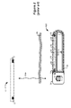
- FIGS. 5A and 5B provide exploded bottom and top views, respectively, of the main parts that comprise the external controller 510, including a back cover 504, a front cover 512, an electronics chassis 508, a printed circuit board (PCB) 520, and battery/coil components 506.
- the battery/coil components 506 include the coils 62a and 62b, the ferrite core 128, and the battery 126. Two coils 62a and 62b are preferred so that the external controller 510 can benefit from the technique disclosed in the '869 Publication discussed in the Background. This however is not strictly necessary and the external controller 510 can comprise only one communication coil, or more than two.
- the battery/coil components 506 and the PCB 520 will be incorporated into the electronics chassis 508 during manufacturing, resulting in a sub-assembly 610, which will be discussed further with respect to FIGS. 6A-6C .
- FIGS. 5A and 5B show only one PCB 520, it is possible to include more than one PCB in the external controller 510.
- the external controller can include two smaller PCBs.
- one PCB can be placed on one side of the electronics chassis 508 and another PCB on the other side.
- a second PCB can be attached to the PCB that is incorporated into the electronics chassis. Showing one PCB 520 is merely exemplary.
- the front cover 512, back cover 504, and the electronics chassis 508 are preferably comprised of mold-injected plastic.
- the electronics chassis 508 incorporates pins 602 and 604 protruding from both its front and back sides, which will be connected to the coils 62a and 62b and to the PCB 520 during manufacturing, as will be explained in detail later.
- the front cover 512 includes a clear display window 536 though which the display 265 can be seen. As shown in FIG. 5B , the display 265 couples to a connector 533 on the front side of the PCB 520 via a flexible bus 534. (The display 265 is not shown in FIG. 5A for simplicity).
- the flexible bus 534 allows the display 265 to be bent over as indicated by arrow 536 so that its front side shows through the display window 536.
- the front cover 512 has one or more mechanical features (not shown) that ensure the display 265 is property aligned with and securely attached to the display window 536.
- the buttons 270 comprise a single rubber gasket as shown in FIG. 5A , which meet with various switches 122 on the front side of the PCB 520. (The buttons 270 are not shown in FIG. 5A for simplicity).
- One or more holes (not shown) in the front cover 512, back cover 504, or the PCB 520 can align with a speaker (not shown) to facilitate transmission of audible indicators.
- a USB port 300 is coupled to the back side of the PCB 520, and is made accessible through a hole 572 in the side of the chassis 508.
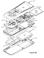
- the battery/coil components 506 and the PCB 520 will be incorporated into the electronics chassis 508 during manufacturing, resulting in a sub-assembly 610, which is shown in FIGS. 6A , 6B , and 6C in back, front, and side views, respectively.
- the electronics chassis 508 offers a secure and durable structure on which the coils 62a and 62b, the ferrite core 128, and the battery 126 can be placed, and additionally will form the sides of the external controller 510 once manufacturing is completed.
- the pre-wound coils 62a and 62b are coupled to the back side of the electronics chassis 508.
- the chassis 508 is formed with a protrusion 518 inside of which a pocket 528 is formed for housing telemetry coil 62b and the ferrite core 128 around which it is wrapped.
- the pocket 528 is made with a shape substantially corresponding to the shape of the wound coil 62b/ferrite core 128 combination. This correspondence in shape enables this combination to fit snuggly into the pocket 528, which prevents it from moving.
- the pocket 528 can be filled with epoxy (not shown) to further limit movement to protect the coil 62b and the fragile ferrite core 128. Even if the ferrite core 128 is thereafter cracked, for example, because the external controller 510 is dropped, the epoxy will hold the cracked pieces in place, and the ferrite core 128 will still function adequately and will not damage other components. Because the pocket 528 is also suitably deep, the coil 62b and ferrite core 128 are recessed below the top of the protrusion 518 (see the side view of FIG. 6C ), which prevents them from being damaged in subsequent manufacturing steps.
- Protrusion 518 also creates a recess 530 around it, as best seen in FIG 5A .
- Recess 530 is used for easy and secure placement of coil 62a, as shown in FIG. 6A . Once coil 62a is placed into recess 530, it too can be epoxied in place.
- the walls of the recess 530 can be made high enough such that the coils 62a does not protrude from the recess 530, although providing such complete protection is of lesser concern for the ferrite-less coil 62a.
- coils 62a and 62b After the coils 62a and 62b have been coupled to the electronics chassis 508, they can be electrically connected to pins 602 and 604 respectively, as best shown in FIG. 6A . As mentioned earlier, these pins 602 and 604 are ultimately used to connect the coils 62a and 62b to the PCB 520, as will be discussed later. Coil 62b has loose ends 514 which are soldered to pins 604, and coil 62a has loose ends 516 which are soldered to pins 602. Such soldering can occur by hand, or can be automated. As best shown in FIG. 5A , the pins 602 and 604 are recessed within the chassis 508 so that they do not protrude above its top (e.g., above the protrusion 518).
- pins 602 and 604 can be incorporated into the chassis 508 when it is mold injected, or can be passed through the chassis 508 after the coils 62a and 62b are soldered to them.
- coil 62a has four loose ends 516
- coil 62b has four loose ends 514, and accordingly there are four pins 602 and four pins 604 to receive these loose ends, respectively.
- each of coils 62a and 62b actually comprises two separate windings to benefit from the technique described in U.S. Patent Publication 2009/0024179 , with which the reader is assumed familiar.
- the '179 Publication describes how a communication coil in an external controller can be split into two parts.
- the secondary winding can be coupled to the battery 126 via a diode, such that when the primary winding of the coil is resonating, some of the energy is shunted off and directed back to the battery 126.
- the coil 62a could comprise two loose ends 516
- the coil 62b could comprise two loose ends 514
- the chassis 508 could accordingly comprises only two pins 602 and two pins 604.
- the battery 126 is next connected to the back side of the chassis.
- the chassis 508 is formed with an indentation 532 which is roughly shaped to match the curved edges of the battery 126.
- the bottom of the indentation is lined with an adhesive, such as strips of double-sided foam tape 542. Tape 542 adequately holds the battery 126, and provides some cushion to protect the battery 126 from mechanical damage.
- the battery 126 could also be affixed to the chassis 508 in other well-known ways.
- the walls of the indentation 532 could be made high enough such that the battery 126 would not protrude above those walls, thus completely recessing the battery 126 for maximum protection.
- pocket 528, recess 530, and indentation 532 have each been given separate names for clarity, it should be understood that each can be considered generically as a "recess" for purposes of this disclosure.
- the PCB 520 is affixed to the chassis 508.
- the PCB 520 is at this point essentially fully formed using traditional surface mounting technology.
- Most of the components 133 ( FIG. 4 ) are mounted to the back side of the PCB 520 (i.e., that which faces the chassis 508), but some components such as the switches 122 and the display connector 533 are mounted to the front side of the PCB 520, as shown in FIG. 6B .
- the front side of PCB 520 can also contain a test connector 535 for testing the sub-assembly 610 once it is completed, and before enclosure of the sub-assembly between the front cover 512 and the back cover 504.
- the PCB 520 is positioned into the front side of the chassis 508, and as shown in FIG. 6B , the PCB 520 is shaped to match the contours of the chassis 508 to ensure a snug fit.
- clamps 538 are used, which clamps 538 were formed into the chassis 508 when it was mold injected.
- the PCB 520 can be "clicked" inside of the clamps 538 to achieve a secure fit.
- FIG. 6C that the PCB 520 is slightly recessed from the top edge 637 of the chassis 508. This protects the edges of the PCB 520, and also assists in protecting any components 133 ( FIG. 4 ) mounted to the front side of the PCB 520 from mechanical damage.
- the PCB is formed with through-holes 702 and 704.
- these through-holes 702 and 704 are respectively penetrated by the pins 602 and 604 on the front side of the chassis 508.
- these pins 602 and 604 were earlier coupled to the coils 62a and 62b on the back side of the chassis 508.
- the pins 602 and 604 protrude through the holes 702 and 704, they are then soldered, for example, by hand or in an automated fashion. This couples the coils 62a and 62b to appropriate circuit nodes on the PCB 520, i.e., to nodes meeting with the telemetry circuitry on the PCB 520.
- the battery 126 is coupled to the PCB 520.
- the battery 126 is formed with a connector 541.
- the chassis 508 is formed with a hole 543, and the PCB 520 includes a connector 544 designed to mate with the battery's connector 541, as best shown in FIG. 5A .
- the hole 543 and PCB connector 544 align, such that the battery connector 541 can mate to the PCB connector 544, as shown in FIG. 6A , thereby coupling the battery 126 to appropriate circuitry nodes on the PCB 520.
- the sub-assembly 610 is fully manufactured, and can be tested (e.g., using connector 535) if necessary.
- the sub-assembly 610 comprises a mechanically stable unit which is easy to manufacture, and which is also easy to manipulate during subsequent manufacturing steps.
- the coils 62a and 62b, and in particular the fragile ferrite core 128, are protected and secured by virtue of being recessed and affixed within the electronic chassis 508, and the battery 126 is similarly protected although perhaps to a lesser degree if not completely recessed.
- the coils 62a and 62b are not directly soldered to the PCB 520, but instead are connected to the PCB 520 by the electronic chassis 508 (or more specifically, pins 602 and 604) as an intermediary.
- the electronic chassis 508 or more specifically, pins 602 and 604 as an intermediary.
- This is a much simpler and more reliable way of connecting the coils 62a and 62b to the PCB 520, as this connection only involves soldering of the pins 602 and 604 to the PCB 520 as opposed to the otherwise fragile loose ends 514 and 516 of the coils.
- the chassis 508 generally lies in a different parallel plane from the PCB 520. This leaves room between the PCB 520 and the chassis 508 for components 133 ( FIG.
- Holes 638 are provided in the side of the chassis 508 and the PCB 520 to accommodate plastic soft key buttons 278 and an unlock button 281 ( FIG. 3 ), which plastic buttons are slid into position where they interface with switches 633 ( FIGS. 6B and 6C ) extending from the edges of the PCB 520. Positioning buttons 278 and 281 in this fashion ultimately integrates them into the edges of the external controller 510.
- the gasket comprising the buttons 270 is placed over the switches 122.
- the display 265 is coupled to the connector 533 ( FIG. 5A ), flipped over as discussed previously, and if necessary affixed to the front cover 512.
- FIG. 5A shows that the front cover 512, chassis 508, PCB 520, and the back cover 504 all comprise aligned bolt holes 502. While only one such set of bolt holes 502 is labeled in FIG. 5A , one will notice that six such sets appear around the periphery of these components.
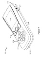
- the completed external controller 510 is shown in FIG. 7 .
- the chassis 508 (or sub-assembly 610 at this stage), as well as stabilizing the electrical components during manufacturing, also forms the outside edges of the external controller 510, and as such the case of the external controller 510 is made up of three pieces: the front cover 512, the chassis 508, and the back cover 504.
- Traditional external controllers typically only use front and back covers, which are bolted together in a clam-shell arrangement, and thus require the internal electronics to be somehow affixed to one of the front and back covers, or both. Because there is no need to affix the electronics to the front or back covers in the external controller 510, its design is simpler from this perspective.
- the external case of the external controller 510 comprises three different structures (the front cover 512, the chassis 508, and the back cover 504), its design is sturdy.
- the back cover 504 could include a door for accessing the battery 126 in case it needs maintenance or changing.
- the back cover 504 could also include contacts to allow the battery 126 to be recharged while sitting in a charging cradle.
- buttons 270A can provide basic external controller 510 functionality, and may include buttons for increasing and decreasing the level of stimulation, or for halting stimulation altogether.
- buttons 270B can be relegated to controlling more advanced functions in the external controller 510, and may be used to navigate through the various menus provided by the user interface.
Description
- The present invention relates to the design and packaging of an external telemetry device having particular applicability to implantable medical device systems.
- Implantable stimulation devices are devices that generate and deliver electrical stimuli to body nerves and tissues for the therapy of various biological disorders. Examples of such devices include pacemakers for treating cardiac arrhythmia, defibrillators for treating cardiac fibrillation, cochlear stimulators for treating deafness, retinal stimulators for treating blindness, muscle stimulators for producing coordinated limb movement, spinal cord stimulators for treating chronic pain, cortical and deep brain stimulators for treating motor and psychological disorders, and other neural stimulators for treating urinary incontinence, sleep apnea, shoulder sublaxation and the like. The present invention may find applicability in all such applications, although the description that follows will generally focus on the use of the invention within a Spinal Cord Stimulation (SCS) system, such as that disclosed in
U.S. Patent 6,516,227 . - Spinal cord stimulation is a well-accepted clinical method for reducing pain in certain populations of patients. As shown in
FIG. 1 , a SCS system typically includes an Implantable Pulse Generator (IPG) 100, which includes abiocompatible case 30 formed of titanium for example. Thecase 30 typically holds the circuitry and power source or battery necessary for the IPG to function, although IPGs can also be powered via external RF energy and without a battery. The IPG 100 is coupled toelectrodes 106 via one or more electrode leads (twosuch leads electrodes 106 form anelectrode array 110. Theelectrodes 106 are carried on aflexible body 108, which also houses theindividual signal wires lead 102, labeled E1-E8, and eight electrodes onlead 104, labeled E9-E16. However, the number of leads and electrodes is application specific and therefore can vary. - Portions of an IPG system are shown in
FIG. 2 in cross section, and include the IPG 100 and anexternal controller 12. The IPG 100 typically includes an electronic substrate assembly 14 including a printed circuit board (PCB) 16, along with variouselectronic components 20, such as microprocessors, integrated circuits, and capacitors mounted to the PCB 16. Two coils are generally present in the IPG 100, atelemetry coil 13 used to transmit/receive data to/from theexternal controller 12, and acharging coil 18 for charging or recharging the IPG's power source orbattery 26 using an external charger (not shown). Thetelemetry coil 13 can be mounted within theheader connector 36 as shown, or can be housed within thecase 30. - As just noted, an
external controller 12, such as a hand-held programmer or a clinician's programmer, is used to wirelessly send data to and receive data from the IPG 100. For example, theexternal controller 12 can send programming data to the IPG 100 to set the therapy the IPG 100 will provide to the patient. Also, theexternal controller 12 can act as a receiver of data from the IPG 100, such as various data reporting on the IPG's status. - The communication of data to and from the
external controller 12 occurs via magnetic inductive coupling. When data is to be sent from theexternal controller 12 to the IPG 100 for example,coil 17 is energized with an alternating current (AC). Such energizing of thecoil 17 to transfer data can occur using a Frequency Shift Keying (FSK) protocol, for example, such as disclosed inU.S. Patent Application Publication 2009/0024179 . Energizing thecoil 17 induces an electromagnetic field, which in turn induces a current in the IPG'stelemetry coil 13, which current can then be demodulated to recover the original data. Communication from the IPG 100 to theexternal controller 12 occurs in essentially the same way. As is well known, inductive transmission of data or power occurs transcutaneously, i.e., through the patient'stissue 25, making it particularly useful in a medical implantable device system. - An
external controller 210 disclosed inU.S. Patent Publication 2009/0118796 is shown inFIG. 3 (a different external controller is disclosed inWO 2008/014022 A1 ). Thisexternal controller 210 may integrate the functions of an external controller and an external charger that wirelessly provides power to the IPG's battery, but such battery charging aspects are not shown inFIG. 3 for simplicity.External controller 210 comprises a user interface, which is somewhat similar to a cell phone or to other external controllers used in the art, in that it includes adisplay 265 andvarious buttons 270.Soft key buttons 278 can be used to select various functions, which functions will vary depending on the status of the menu options available at any given time. A speaker is also included within the housing of the external controller to provide audio cues to the user (not shown). Alternatively, a vibration motor can provide feedback for users with hearing impairments or others who would like to turn the audio cues off.Unlock button 281, recessed into the side of the housing, can be used to unlock the buttons, if they become automatically or manually locked.External controller 210 also has aUSB port 300, which can connect to a charging coil (as discussed in detail in the '796 Publication), to a computer, or to a power source (a wall outlet) to either power the external controller directly or to charge its battery 126 (FIG. 4 ). - The user interface generally allows the user to telemeter data (such as a new therapy program) from the
external controller 210 to the IPG 100, or to monitor various forms of status feedback from the IPG. The software in the controller 210 (preferably implemented as microcode accessible by thecontroller 210's microcontroller) accordingly provides logical menu options to thedisplay 265. For example, when the controller is first turned on, thedisplay 265 may provide selectable options for the user to either program the IPG 100 or to change stimulation settings. - The internal structure of
external controller 210, with itscover 215 removed, is shown inFIG. 4 . As shown, a printed circuit board (PCB) 120 is central to the internal construction of thecontroller 210. The front side of the PCB 120 carries aspects of the user interface, including thedisplay 265 and pressure-sensitive switches 122 for receiving presses to the various user interface buttons 270 (FIG. 3 ). Theexternal controller 210 controls data telemetry by energizing at least onecoil telemetry coils battery 126 along with other integrated and discrete components necessary to implement the functionality of the external controller are located on the back side of thePCB 120. Thebattery 126 can comprise a Lithium (Li)-ion battery or a Li-ion polymer battery for example. - As seen in the back and side views of
FIG. 4 , the twotelemetry coils axes PCB 120, whilecoil 62b is wrapped around aferrite core 128. Further discussion of the benefits of orthogonally-orientedtelemetry coils U.S. Patent Publication 2009/0069869 , which with the reader is assumed familiar. Briefly, when used to transmit data, the twocoils external controller 210 and thetelemetry coil 13 in the IPG 100. Shoulddual coils IPG 100, the two coils are used in conjunction with receiver circuitry which likewise phase shifts the received modulated data signals from each coil and presents their sum to typical demodulation circuitry. - After they are wound, the
telemetry coils PCB 120, and thecoils ferrite core 128 around whichcoil 62b is wound) must then be secured in place, usually by affixing them to the PCB using epoxy. These are cumbersome steps in the manufacturing process, and are prone to failure or reliability problems. Soldering and epoxying thecoils FIG. 4 ) have already been surface mounted to thePCB 120. This risks damaging these other components 133. Additionally, extra care must be taken to well affixcoil 62b to the PCB 120, in particular because of the fragile nature of theferrite core 128, which is made of material having high magnetic permeability such as MnZn or NiZn and is prone to fracture. Even after theferrite core 128 is secured, it is still generally exposed and protrudes from the PCB 120. Thus, theferrite core 128 can be easily damaged, should it be bumped during remaining steps in the manufacturing process. - The external controller's
battery 126 has similar manufacturing concerns. It too must be secured and soldered to thePCB 120 in some fashion, which can likewise damage the various components 133 previously surface mounted to the PCB. And like thecoils ferrite core 128, thebattery 126 protrudes from thePCB 120 and is susceptible to damage. - In addition to these problems, the mechanical design of the
external controller 210 has another disadvantage in that the telemetry coils 62a and 62b, theferrite core 128, and thebattery 126 cover a large portion of the surface area of the back ofPCB 120. The various other components 133 surface mounted to thePCB 120 should not be placed underneath such areas where thecoils ferrite core 128, and thebattery 126 will be affixed, and thus space on thePCB 120 must be reserved for these additional structures. Reserving space on thePCB 120 for these additional structures limits where the other components 133 can be surface mounted, and can complicate routing and layout of thePCB 120. Reserving space on thePCB 120 for thecoils ferrite core 128, and thebattery 126 also generally means that thePCB 120 will need to be larger than would otherwise be necessary if thePCB 120 were only to accommodate the components 133. - The inventors of the present invention recognize the existence of these problems in prior art external controllers and provide solutions to these problems in this disclosure.
-
-
FIG. 1 shows an implantable pulse generator (IPG), and the manner in which an electrode array is coupled to the IPG, in accordance with the prior art. -
FIG. 2 shows wireless communication of data between an external controller and an IPG, in accordance with the prior art. -
FIG. 3 shows an external controller, in accordance with the prior art. -
FIG. 4 shows the internal components of the external controller ofFIG. 3 , in accordance with the prior art. -
FIGS. 5A-5B show exploded bottom and top views, respectively, of internal components of an improved external controller, in accordance with an embodiment of the present invention. -
FIG. 6A-6C show back, top, and side views, respectively, of a sub-assembly used in the manufacture of the improved external controller ofFIGS. 5A-5B , in accordance with an embodiment of the present invention. -
FIG. 7 shows a perspective view of the improved external controller upon completion of its manufacture. - The description that follows relates to use of the invention within a spinal cord stimulation (SCS) system. However, the invention is not so limited. Rather, the invention may be used with any type of implantable medical device system that could benefit from an improved structural design of a data telemetry device used to communicate with an implanted device. For example, the present invention may be used as part of a system employing an implantable sensor, an implantable pump, a pacemaker, a defibrillator, a cochlear stimulator, a retinal stimulator, a stimulator configured to produce coordinated limb movement, a cortical and deep brain stimulator, or in any other neural stimulator configured to treat any of a variety of conditions.
- An improved
external controller 510 is illustrated inFIGS. 5A-5B , which offers significant improvements in design and manufacturing over prior art external controllers such as the external controller 210 (FIGS. 3 and4 ) discussed in the Background. To the extent that similar structures in theexternal controller 210 are used in the improvedexternal controller 510, they retain the same element numerals, and are not again described for simplicity. -
FIGS. 5A and5B provide exploded bottom and top views, respectively, of the main parts that comprise theexternal controller 510, including aback cover 504, afront cover 512, anelectronics chassis 508, a printed circuit board (PCB) 520, and battery/coil components 506. The battery/coil components 506 include thecoils ferrite core 128, and thebattery 126. Twocoils external controller 510 can benefit from the technique disclosed in the '869 Publication discussed in the Background. This however is not strictly necessary and theexternal controller 510 can comprise only one communication coil, or more than two. The battery/coil components 506 and thePCB 520 will be incorporated into theelectronics chassis 508 during manufacturing, resulting in a sub-assembly 610, which will be discussed further with respect toFIGS. 6A-6C . - It should be noted that, while
FIGS. 5A and5B show only onePCB 520, it is possible to include more than one PCB in theexternal controller 510. For example, instead of thePCB 520, the external controller can include two smaller PCBs. In some embodiments, one PCB can be placed on one side of theelectronics chassis 508 and another PCB on the other side. In other embodiments, a second PCB can be attached to the PCB that is incorporated into the electronics chassis. Showing onePCB 520 is merely exemplary. - The
front cover 512,back cover 504, and theelectronics chassis 508 are preferably comprised of mold-injected plastic. Theelectronics chassis 508 incorporatespins coils PCB 520 during manufacturing, as will be explained in detail later. Thefront cover 512 includes aclear display window 536 though which thedisplay 265 can be seen. As shown inFIG. 5B , thedisplay 265 couples to aconnector 533 on the front side of thePCB 520 via aflexible bus 534. (Thedisplay 265 is not shown inFIG. 5A for simplicity). Theflexible bus 534 allows thedisplay 265 to be bent over as indicated byarrow 536 so that its front side shows through thedisplay window 536. Thefront cover 512 has one or more mechanical features (not shown) that ensure thedisplay 265 is property aligned with and securely attached to thedisplay window 536. Thebuttons 270 comprise a single rubber gasket as shown inFIG. 5A , which meet withvarious switches 122 on the front side of thePCB 520. (Thebuttons 270 are not shown inFIG. 5A for simplicity). One or more holes (not shown) in thefront cover 512,back cover 504, or thePCB 520 can align with a speaker (not shown) to facilitate transmission of audible indicators. AUSB port 300 is coupled to the back side of thePCB 520, and is made accessible through ahole 572 in the side of thechassis 508. - As noted earlier, the battery/
coil components 506 and thePCB 520 will be incorporated into theelectronics chassis 508 during manufacturing, resulting in a sub-assembly 610, which is shown inFIGS. 6A ,6B , and6C in back, front, and side views, respectively. Theelectronics chassis 508 offers a secure and durable structure on which thecoils ferrite core 128, and thebattery 126 can be placed, and additionally will form the sides of theexternal controller 510 once manufacturing is completed. - Manufacture of the sub-assembly 610 occurs as follows. First, the
pre-wound coils electronics chassis 508. To assist in placement of thecoils FIG. 5A , thechassis 508 is formed with aprotrusion 518 inside of which apocket 528 is formed forhousing telemetry coil 62b and theferrite core 128 around which it is wrapped. Thepocket 528 is made with a shape substantially corresponding to the shape of thewound coil 62b/ferrite core 128 combination. This correspondence in shape enables this combination to fit snuggly into thepocket 528, which prevents it from moving. After the ferrite andtelemetry coil 62b are placed in thepocket 528, as shown inFIG. 6A , thepocket 528 can be filled with epoxy (not shown) to further limit movement to protect thecoil 62b and thefragile ferrite core 128. Even if theferrite core 128 is thereafter cracked, for example, because theexternal controller 510 is dropped, the epoxy will hold the cracked pieces in place, and theferrite core 128 will still function adequately and will not damage other components. Because thepocket 528 is also suitably deep, thecoil 62b andferrite core 128 are recessed below the top of the protrusion 518 (see the side view ofFIG. 6C ), which prevents them from being damaged in subsequent manufacturing steps. -
Protrusion 518 also creates arecess 530 around it, as best seen inFIG 5A .Recess 530 is used for easy and secure placement ofcoil 62a, as shown inFIG. 6A . Oncecoil 62a is placed intorecess 530, it too can be epoxied in place. Although not shown, the walls of therecess 530 can be made high enough such that thecoils 62a does not protrude from therecess 530, although providing such complete protection is of lesser concern for theferrite-less coil 62a. - After the
coils electronics chassis 508, they can be electrically connected topins FIG. 6A . As mentioned earlier, thesepins coils PCB 520, as will be discussed later.Coil 62b hasloose ends 514 which are soldered topins 604, andcoil 62a hasloose ends 516 which are soldered topins 602. Such soldering can occur by hand, or can be automated. As best shown inFIG. 5A , thepins chassis 508 so that they do not protrude above its top (e.g., above the protrusion 518). (See also the side view ofFIG. 6C , which does not show protrusion of thepins 602 or 604). Recessing thepins loose ends Pins chassis 508 when it is mold injected, or can be passed through thechassis 508 after thecoils - As shown,
coil 62a has fourloose ends 516, andcoil 62b has fourloose ends 514, and accordingly there are fourpins 602 and fourpins 604 to receive these loose ends, respectively. This is because, in the illustrated embodiment, each ofcoils U.S. Patent Publication 2009/0024179 , with which the reader is assumed familiar. Briefly, the '179 Publication describes how a communication coil in an external controller can be split into two parts. The secondary winding can be coupled to thebattery 126 via a diode, such that when the primary winding of the coil is resonating, some of the energy is shunted off and directed back to thebattery 126. However, use of the technique of the '179 Publication is not required, and instead, thecoil 62a could comprise twoloose ends 516, thecoil 62b could comprise twoloose ends 514, and thechassis 508 could accordingly comprises only twopins 602 and twopins 604. - After connection of the
coils electronics chassis 508, thebattery 126 is next connected to the back side of the chassis. As best seen inFIG. 5A , thechassis 508 is formed with anindentation 532 which is roughly shaped to match the curved edges of thebattery 126. To hold thebattery 126 within theindentation 532, the bottom of the indentation is lined with an adhesive, such as strips of double-sided foam tape 542.Tape 542 adequately holds thebattery 126, and provides some cushion to protect thebattery 126 from mechanical damage. However, thebattery 126 could also be affixed to thechassis 508 in other well-known ways. Although not shown, the walls of theindentation 532 could be made high enough such that thebattery 126 would not protrude above those walls, thus completely recessing thebattery 126 for maximum protection. - While
pocket 528,recess 530, andindentation 532 have each been given separate names for clarity, it should be understood that each can be considered generically as a "recess" for purposes of this disclosure. - After the
coils battery 126 have been affixed to theelectronics chassis 508, thePCB 520 is affixed to thechassis 508. ThePCB 520 is at this point essentially fully formed using traditional surface mounting technology. Most of the components 133 (FIG. 4 ) are mounted to the back side of the PCB 520 (i.e., that which faces the chassis 508), but some components such as theswitches 122 and thedisplay connector 533 are mounted to the front side of thePCB 520, as shown inFIG. 6B . The front side ofPCB 520 can also contain atest connector 535 for testing the sub-assembly 610 once it is completed, and before enclosure of the sub-assembly between thefront cover 512 and theback cover 504. - The
PCB 520 is positioned into the front side of thechassis 508, and as shown inFIG. 6B , thePCB 520 is shaped to match the contours of thechassis 508 to ensure a snug fit. To further assist in securing thePCB 520 within thechassis 508, clamps 538 are used, which clamps 538 were formed into thechassis 508 when it was mold injected. ThePCB 520 can be "clicked" inside of theclamps 538 to achieve a secure fit. Notice inFIG. 6C that thePCB 520 is slightly recessed from thetop edge 637 of thechassis 508. This protects the edges of thePCB 520, and also assists in protecting any components 133 (FIG. 4 ) mounted to the front side of thePCB 520 from mechanical damage. - As shown in
FIG. 6B , the PCB is formed with through-holes PCB 520 is secured within thechassis 508, these through-holes pins chassis 508. By way of review, thesepins coils chassis 508. When thepins holes coils PCB 520, i.e., to nodes meeting with the telemetry circuitry on thePCB 520. - Thereafter, the
battery 126 is coupled to thePCB 520. Thebattery 126 is formed with aconnector 541. Thechassis 508 is formed with ahole 543, and thePCB 520 includes a connector 544 designed to mate with the battery'sconnector 541, as best shown inFIG. 5A . When thePCB 520 is positioned within thechassis 508, thehole 543 and PCB connector 544 align, such that thebattery connector 541 can mate to the PCB connector 544, as shown inFIG. 6A , thereby coupling thebattery 126 to appropriate circuitry nodes on thePCB 520. As this point, thesub-assembly 610 is fully manufactured, and can be tested (e.g., using connector 535) if necessary. - Before continuing with remaining steps in the assembly of the
external controller 510, some benefits provided by the sub-assembly 610 can be appreciated in contradistinction to the prior art external controller ofFIGS. 3 and4 . The sub-assembly 610 comprises a mechanically stable unit which is easy to manufacture, and which is also easy to manipulate during subsequent manufacturing steps. Thecoils fragile ferrite core 128, are protected and secured by virtue of being recessed and affixed within theelectronic chassis 508, and thebattery 126 is similarly protected although perhaps to a lesser degree if not completely recessed. Additionally, thecoils PCB 520, but instead are connected to thePCB 520 by the electronic chassis 508 (or more specifically, pins 602 and 604) as an intermediary. This is a much simpler and more reliable way of connecting thecoils PCB 520, as this connection only involves soldering of thepins PCB 520 as opposed to the otherwise fragileloose ends chassis 508 generally lies in a different parallel plane from thePCB 520. This leaves room between thePCB 520 and thechassis 508 for components 133 (FIG. 4 ) to be placed on thePCB 520, even in spaces underlying thecoils battery 126. As such, no space has to be reserved on thePCB 520 for these additional structures, and the components 133 can therefore be more densely packed and their routing on the PCB facilitated. Obviating the need for additional space also means thePCB 520 can be made smaller if desired. - Once the
sub-assembly 610 is completed, manufacture of the external controller can be completed.Holes 638 are provided in the side of thechassis 508 and thePCB 520 to accommodate plastic softkey buttons 278 and an unlock button 281 (FIG. 3 ), which plastic buttons are slid into position where they interface with switches 633 (FIGS. 6B and6C ) extending from the edges of thePCB 520.Positioning buttons external controller 510. The gasket comprising thebuttons 270 is placed over theswitches 122. Thedisplay 265 is coupled to the connector 533 (FIG. 5A ), flipped over as discussed previously, and if necessary affixed to thefront cover 512. Then, thefront cover 512 and theback cover 504 are positioned in place around thesub-assembly 610, and all of the components are bolted into place. In this regard,FIG. 5A shows that thefront cover 512,chassis 508,PCB 520, and theback cover 504 all comprise aligned bolt holes 502. While only one such set of bolt holes 502 is labeled inFIG. 5A , one will notice that six such sets appear around the periphery of these components. - The completed
external controller 510 is shown inFIG. 7 . Notice that the chassis 508 (or sub-assembly 610 at this stage), as well as stabilizing the electrical components during manufacturing, also forms the outside edges of theexternal controller 510, and as such the case of theexternal controller 510 is made up of three pieces: thefront cover 512, thechassis 508, and theback cover 504. Traditional external controllers typically only use front and back covers, which are bolted together in a clam-shell arrangement, and thus require the internal electronics to be somehow affixed to one of the front and back covers, or both. Because there is no need to affix the electronics to the front or back covers in theexternal controller 510, its design is simpler from this perspective. Moreover, because the external case of theexternal controller 510 comprises three different structures (thefront cover 512, thechassis 508, and the back cover 504), its design is sturdy. - Although not shown, the
back cover 504 could include a door for accessing thebattery 126 in case it needs maintenance or changing. Theback cover 504 could also include contacts to allow thebattery 126 to be recharged while sitting in a charging cradle. - It should be noted that the
front cover 512 has a recessedarea 710. Placing somebuttons 270A, but notother buttons 270B, into the recessedarea 710 helps to differentiate the functionality of these buttons. For example,buttons 270A can provide basicexternal controller 510 functionality, and may include buttons for increasing and decreasing the level of stimulation, or for halting stimulation altogether. By contrast,buttons 270B can be relegated to controlling more advanced functions in theexternal controller 510, and may be used to navigate through the various menus provided by the user interface. - It should be understood that any use of the article "a" in this disclosure and the accompanying claims could mean one, or one or more.
- Although particular embodiments of the present invention have been shown and described, it should be understood that the above discussion is not intended to limit the present invention to these embodiments.
Claims (16)
- An external controller for an implantable medical device, comprising:a chassis;at least one telemetry coil affixed to the chassis, the at least one telemetry coil for communicating with an implantable medical device;a circuit board affixed to the chassis;a battery affixed to the chassis,wherein the telemetry coil and the battery are electrically coupled to the circuit board;a front cover placed proximate to a front side of the chassis; anda back cover placed proximate to a back side of the chassis,wherein the chassis comprises outside edges of the external controller between the front
and back covers; and wherein at least the chassis, the front cover, and the back cover further comprise at least one set of bolt holes for receiving a bolt to fasten the front cover, the back cover, and the chassis together. - The external controller of claim 1, further comprising at least one button integrated into the edges of the external controller.
- The external controller of claim 1, wherein the circuit board is affixed to a first side of the chassis, and wherein the at least one telemetry coil and the battery are affixed to a second side of the chassis.
- The external controller of claim 1, wherein the chassis further comprises a plurality of pins extending through first and second sides of the chassis, and wherein the at least one telemetry coil is electrically coupled to the pins on the first side of the chassis.
- The external controller of claim 4, wherein the circuit board is electrically coupled to the pins on the second side of the chassis.
- The external controller of claim 1, wherein the chassis further comprises clamps formed in the chassis, and wherein the circuit board is affixed within the chassis using the clamps.
- The external controller of claim 1, wherein the chassis further comprises a recess for housing one of the at least one telemetry coil.
- The external controller of claim 7, wherein the one telemetry coil is completely recessed below a top edge of the recess.
- The external controller of claim 7, further comprising a ferrite core, wherein the one telemetry coil is wound around the ferrite core.
- The external controller of claim 7, further comprising epoxy, wherein the recess is at least partially filled with the epoxy to affix the one telemetry coil.
- The external controller of claim 1, wherein at least one telemetry coil affixed to the chassis comprises first and second telemetry coils, and wherein the first and second telemetry coils are wound around axes that are orthogonal.
- The external controller of claim 11, wherein the chassis further comprises a first recess for the first telemetry coil and a second recess for the second telemetry coil.
- The external controller of claim 1, wherein the chassis further comprises a recess for holding the battery.
- The external controller of claim 13, further comprising an adhesive, wherein the battery is affixed in the recess using the adhesive.
- The external controller of claim 1, wherein the battery further comprises a first connector, wherein the circuit board further comprises a second connector, wherein the chassis further comprises a hole, and wherein the battery electrically couples to the second connector through the hole.
- A method of manufacturing the external controller of any one of claims 1-15 using a chassis comprising a plurality of pins, the method comprising:forming a sub-assembly for the external controller, comprising affixing at least one telemetry coil to the chassis, the at least one telemetry coil for communicating with an implantable medical device;electrically coupling the at least one telemetry coil to the pins;affixing a circuit board to the chassis; andelectrically coupling the circuit board to the pins, thereby electrically coupling the at least one telemetry coil to the circuit board.
Applications Claiming Priority (2)
| Application Number | Priority Date | Filing Date | Title |
|---|---|---|---|
| US40634110P | 2010-10-25 | 2010-10-25 | |
| PCT/US2011/054880 WO2012057977A1 (en) | 2010-10-25 | 2011-10-05 | An external controller for an implantable medical device formed using a sub-assembly |
Publications (2)
| Publication Number | Publication Date |
|---|---|
| EP2632545A1 EP2632545A1 (en) | 2013-09-04 |
| EP2632545B1 true EP2632545B1 (en) | 2016-11-23 |
Family
ID=44800287
Family Applications (1)
| Application Number | Title | Priority Date | Filing Date |
|---|---|---|---|
| EP11770026.0A Active EP2632545B1 (en) | 2010-10-25 | 2011-10-05 | An external controller for an implantable medical device formed using a sub-assembly |
Country Status (6)
| Country | Link |
|---|---|
| US (1) | US20120101551A1 (en) |
| EP (1) | EP2632545B1 (en) |
| JP (1) | JP5862904B2 (en) |
| AU (1) | AU2011320830B2 (en) |
| CA (1) | CA2813085A1 (en) |
| WO (1) | WO2012057977A1 (en) |
Families Citing this family (22)
| Publication number | Priority date | Publication date | Assignee | Title |
|---|---|---|---|---|
| AU2011329370B2 (en) | 2010-11-17 | 2014-11-20 | Boston Scientific Neuromodulation Corporation | External trial stimulator useable in an implantable neurostimulator system |
| US9130384B2 (en) * | 2011-10-06 | 2015-09-08 | Prong, Inc. | Smart phone and/or consumer electronics device charger system |
| AU2012332102B2 (en) * | 2011-11-04 | 2017-05-04 | Nevro Corporation | Medical device communication and charding assemblies for use with implantable signal generators |
| CN103855339B (en) * | 2012-12-07 | 2016-08-03 | 深圳市华宝新能源有限公司 | The electronic installation of recyclable battery |
| US9067072B2 (en) | 2013-03-06 | 2015-06-30 | Boston Scientific Neuromodulation Corporation | Switchable dual-coil communication circuitry for extending communication range in an implantable medical device system |
| AU2014259681B2 (en) | 2013-05-03 | 2018-08-09 | Nevro Corporation | Molded headers for implantable signal generators, and associated systems and methods |
| US9327135B2 (en) | 2013-06-04 | 2016-05-03 | Boston Scientific Neuromodulation Corporation | External device for determining an optimal implantable medical device for a patient using information determined during an external trial stimulation phase |
| WO2015021348A2 (en) | 2013-08-09 | 2015-02-12 | Inspire Medical Systems, Inc. | Patient control for implantable medical device |
| CN106464029B (en) * | 2014-04-15 | 2020-08-04 | 哈特威尔公司 | Improvements in transcutaneous energy transfer systems |
| AU2015264561B2 (en) | 2014-05-20 | 2020-02-20 | Nevro Corporation | Implanted pulse generators with reduced power consumption via signal strength/duration characteristics, and associated systems and methods |
| USD752763S1 (en) * | 2014-08-08 | 2016-03-29 | Inspire Medical Systems, Inc. | Patient control |
| AU2015336218B2 (en) | 2014-10-22 | 2020-07-23 | Nevro Corp. | Systems and methods for extending the life of an implanted pulse generator battery |
| US9929584B2 (en) | 2014-10-30 | 2018-03-27 | Boston Scientific Neuromodulation Corporation | External charging coil assembly for charging a medical device |
| US10105545B2 (en) | 2015-03-12 | 2018-10-23 | Boston Scientific Neuromodulation Corporation | Assembly with a coaxial audio connector for charging an implantable medical device |
| USD801538S1 (en) | 2015-12-16 | 2017-10-31 | Inspire Medical Systems, Inc. | Patient control |
| USD810306S1 (en) | 2016-03-24 | 2018-02-13 | Inspire Medical Systems, Inc. | Patient control |
| USD840357S1 (en) * | 2016-08-30 | 2019-02-12 | Qingdao Bright Medical Manufacturing Co., Ltd. | Control device |
| USD840358S1 (en) * | 2016-11-10 | 2019-02-12 | Qingdao Bright Medical Manufacturing Co., Ltd. | Control device |
| US11633604B2 (en) | 2018-01-30 | 2023-04-25 | Nevro Corp. | Efficient use of an implantable pulse generator battery, and associated systems and methods |
| WO2019213181A1 (en) | 2018-05-01 | 2019-11-07 | Sandhu Prabdeep | A 2.4 ghz radio antenna for implanted medical devices, and associated systems and methods |
| US10933238B2 (en) | 2019-01-31 | 2021-03-02 | Nevro Corp. | Power control circuit for sterilized devices, and associated systems and methods |
| USD1010831S1 (en) | 2021-02-23 | 2024-01-09 | Inspire Medical Systems, Inc. | Patient control |
Family Cites Families (13)
| Publication number | Priority date | Publication date | Assignee | Title |
|---|---|---|---|---|
| US5848152A (en) * | 1995-09-26 | 1998-12-08 | Motorola, Inc. | Communication device having interchangeable faceplates and active keypad cover |
| JP2978100B2 (en) * | 1995-10-25 | 1999-11-15 | ティーディーケイ株式会社 | Contactless charger |
| US6516227B1 (en) | 1999-07-27 | 2003-02-04 | Advanced Bionics Corporation | Rechargeable spinal cord stimulator system |
| US20030050676A1 (en) * | 2001-09-11 | 2003-03-13 | Mark Hubelbank | Suspension of implantable device |
| US20040230246A1 (en) * | 2003-05-15 | 2004-11-18 | Stein Richard E. | Patient controlled therapy management and diagnostic device with human factors interface |
| US20050075685A1 (en) * | 2003-10-02 | 2005-04-07 | Forsberg John W. | Medical device programmer with infrared communication |
| US7515963B2 (en) * | 2003-12-16 | 2009-04-07 | Cardiac Pacemakers, Inc. | Method of patient initiated electro-cardiogram storage, status query and therapy activation |
| US8068914B1 (en) * | 2004-05-05 | 2011-11-29 | Advanced Bionics, Llc | Speech processor cases |
| US9002445B2 (en) * | 2006-07-28 | 2015-04-07 | Boston Scientific Neuromodulation Corporation | Charger with orthogonal PCB for implantable medical device |
| JP4737109B2 (en) * | 2007-02-20 | 2011-07-27 | セイコーエプソン株式会社 | Non-contact rechargeable electronic equipment |
| US9162068B2 (en) | 2007-07-16 | 2015-10-20 | Boston Scientific Neuromodulation Corporation | Energy efficient resonant driving circuit for magnetically coupled telemetry |
| US20090069869A1 (en) | 2007-09-11 | 2009-03-12 | Advanced Bionics Corporation | Rotating field inductive data telemetry and power transfer in an implantable medical device system |
| US8498716B2 (en) * | 2007-11-05 | 2013-07-30 | Boston Scientific Neuromodulation Corporation | External controller for an implantable medical device system with coupleable external charging coil assembly |
-
2011
- 2011-08-30 US US13/221,527 patent/US20120101551A1/en not_active Abandoned
- 2011-10-05 JP JP2013536643A patent/JP5862904B2/en active Active
- 2011-10-05 EP EP11770026.0A patent/EP2632545B1/en active Active
- 2011-10-05 WO PCT/US2011/054880 patent/WO2012057977A1/en active Application Filing
- 2011-10-05 CA CA2813085A patent/CA2813085A1/en not_active Abandoned
- 2011-10-05 AU AU2011320830A patent/AU2011320830B2/en not_active Ceased
Also Published As
| Publication number | Publication date |
|---|---|
| JP5862904B2 (en) | 2016-02-16 |
| CA2813085A1 (en) | 2012-05-03 |
| AU2011320830A1 (en) | 2013-05-02 |
| US20120101551A1 (en) | 2012-04-26 |
| EP2632545A1 (en) | 2013-09-04 |
| WO2012057977A1 (en) | 2012-05-03 |
| AU2011320830B2 (en) | 2014-07-24 |
| JP2013540561A (en) | 2013-11-07 |
Similar Documents
| Publication | Publication Date | Title |
|---|---|---|
| EP2632545B1 (en) | An external controller for an implantable medical device formed using a sub-assembly | |
| AU2008351351B2 (en) | Printed circuit board communication coil for use in an implantable medical device system | |
| EP2794003B1 (en) | A system for an implantable medical device having an external charger coupleable to accessory charging coils | |
| CA2748898C (en) | External device for communicating with an implantable medical device having data telemetry and charging integrated in a single housing | |
| EP2640460B1 (en) | External trial stimulator useable in an implantable neurostimulator system | |
| EP2185239B1 (en) | Rotating field inductive data telemetry and power transfer in an implantable medical device system | |
| US8175716B2 (en) | Multiple telemetry and/or charging coil configurations for an implantable medical device system | |
| WO2018013324A1 (en) | Holder for maintaining an implantable medical device in a single orientation | |
| AU2013237664B2 (en) | External device for communicating with an implantable medical device having data telemetry and charging integrated in a single housing |
Legal Events
| Date | Code | Title | Description |
|---|---|---|---|
| PUAI | Public reference made under article 153(3) epc to a published international application that has entered the european phase |
Free format text: ORIGINAL CODE: 0009012 |
|
| 17P | Request for examination filed |
Effective date: 20130515 |
|
| AK | Designated contracting states |
Kind code of ref document: A1 Designated state(s): AL AT BE BG CH CY CZ DE DK EE ES FI FR GB GR HR HU IE IS IT LI LT LU LV MC MK MT NL NO PL PT RO RS SE SI SK SM TR |
|
| DAX | Request for extension of the european patent (deleted) | ||
| 17Q | First examination report despatched |
Effective date: 20140627 |
|
| GRAP | Despatch of communication of intention to grant a patent |
Free format text: ORIGINAL CODE: EPIDOSNIGR1 |
|
| INTG | Intention to grant announced |
Effective date: 20160419 |
|
| GRAS | Grant fee paid |
Free format text: ORIGINAL CODE: EPIDOSNIGR3 |
|
| GRAA | (expected) grant |
Free format text: ORIGINAL CODE: 0009210 |
|
| AK | Designated contracting states |
Kind code of ref document: B1 Designated state(s): AL AT BE BG CH CY CZ DE DK EE ES FI FR GB GR HR HU IE IS IT LI LT LU LV MC MK MT NL NO PL PT RO RS SE SI SK SM TR |
|
| REG | Reference to a national code |
Ref country code: GB Ref legal event code: FG4D |
|
| REG | Reference to a national code |
Ref country code: CH Ref legal event code: EP |
|
| REG | Reference to a national code |
Ref country code: IE Ref legal event code: FG4D |
|
| REG | Reference to a national code |
Ref country code: AT Ref legal event code: REF Ref document number: 847322 Country of ref document: AT Kind code of ref document: T Effective date: 20161215 |
|
| REG | Reference to a national code |
Ref country code: DE Ref legal event code: R096 Ref document number: 602011032724 Country of ref document: DE |
|
| PG25 | Lapsed in a contracting state [announced via postgrant information from national office to epo] |
Ref country code: LV Free format text: LAPSE BECAUSE OF FAILURE TO SUBMIT A TRANSLATION OF THE DESCRIPTION OR TO PAY THE FEE WITHIN THE PRESCRIBED TIME-LIMIT Effective date: 20161123 |
|
| REG | Reference to a national code |
Ref country code: LT Ref legal event code: MG4D |
|
| REG | Reference to a national code |
Ref country code: NL Ref legal event code: MP Effective date: 20161123 |
|
| REG | Reference to a national code |
Ref country code: AT Ref legal event code: MK05 Ref document number: 847322 Country of ref document: AT Kind code of ref document: T Effective date: 20161123 |
|
| PG25 | Lapsed in a contracting state [announced via postgrant information from national office to epo] |
Ref country code: NL Free format text: LAPSE BECAUSE OF FAILURE TO SUBMIT A TRANSLATION OF THE DESCRIPTION OR TO PAY THE FEE WITHIN THE PRESCRIBED TIME-LIMIT Effective date: 20161123 Ref country code: LT Free format text: LAPSE BECAUSE OF FAILURE TO SUBMIT A TRANSLATION OF THE DESCRIPTION OR TO PAY THE FEE WITHIN THE PRESCRIBED TIME-LIMIT Effective date: 20161123 Ref country code: NO Free format text: LAPSE BECAUSE OF FAILURE TO SUBMIT A TRANSLATION OF THE DESCRIPTION OR TO PAY THE FEE WITHIN THE PRESCRIBED TIME-LIMIT Effective date: 20170223 Ref country code: SE Free format text: LAPSE BECAUSE OF FAILURE TO SUBMIT A TRANSLATION OF THE DESCRIPTION OR TO PAY THE FEE WITHIN THE PRESCRIBED TIME-LIMIT Effective date: 20161123 Ref country code: GR Free format text: LAPSE BECAUSE OF FAILURE TO SUBMIT A TRANSLATION OF THE DESCRIPTION OR TO PAY THE FEE WITHIN THE PRESCRIBED TIME-LIMIT Effective date: 20170224 |
|
| PG25 | Lapsed in a contracting state [announced via postgrant information from national office to epo] |
Ref country code: PT Free format text: LAPSE BECAUSE OF FAILURE TO SUBMIT A TRANSLATION OF THE DESCRIPTION OR TO PAY THE FEE WITHIN THE PRESCRIBED TIME-LIMIT Effective date: 20170323 Ref country code: PL Free format text: LAPSE BECAUSE OF FAILURE TO SUBMIT A TRANSLATION OF THE DESCRIPTION OR TO PAY THE FEE WITHIN THE PRESCRIBED TIME-LIMIT Effective date: 20161123 Ref country code: RS Free format text: LAPSE BECAUSE OF FAILURE TO SUBMIT A TRANSLATION OF THE DESCRIPTION OR TO PAY THE FEE WITHIN THE PRESCRIBED TIME-LIMIT Effective date: 20161123 Ref country code: FI Free format text: LAPSE BECAUSE OF FAILURE TO SUBMIT A TRANSLATION OF THE DESCRIPTION OR TO PAY THE FEE WITHIN THE PRESCRIBED TIME-LIMIT Effective date: 20161123 Ref country code: AT Free format text: LAPSE BECAUSE OF FAILURE TO SUBMIT A TRANSLATION OF THE DESCRIPTION OR TO PAY THE FEE WITHIN THE PRESCRIBED TIME-LIMIT Effective date: 20161123 Ref country code: ES Free format text: LAPSE BECAUSE OF FAILURE TO SUBMIT A TRANSLATION OF THE DESCRIPTION OR TO PAY THE FEE WITHIN THE PRESCRIBED TIME-LIMIT Effective date: 20161123 Ref country code: HR Free format text: LAPSE BECAUSE OF FAILURE TO SUBMIT A TRANSLATION OF THE DESCRIPTION OR TO PAY THE FEE WITHIN THE PRESCRIBED TIME-LIMIT Effective date: 20161123 |
|
| PG25 | Lapsed in a contracting state [announced via postgrant information from national office to epo] |
Ref country code: SK Free format text: LAPSE BECAUSE OF FAILURE TO SUBMIT A TRANSLATION OF THE DESCRIPTION OR TO PAY THE FEE WITHIN THE PRESCRIBED TIME-LIMIT Effective date: 20161123 Ref country code: CZ Free format text: LAPSE BECAUSE OF FAILURE TO SUBMIT A TRANSLATION OF THE DESCRIPTION OR TO PAY THE FEE WITHIN THE PRESCRIBED TIME-LIMIT Effective date: 20161123 Ref country code: RO Free format text: LAPSE BECAUSE OF FAILURE TO SUBMIT A TRANSLATION OF THE DESCRIPTION OR TO PAY THE FEE WITHIN THE PRESCRIBED TIME-LIMIT Effective date: 20161123 Ref country code: DK Free format text: LAPSE BECAUSE OF FAILURE TO SUBMIT A TRANSLATION OF THE DESCRIPTION OR TO PAY THE FEE WITHIN THE PRESCRIBED TIME-LIMIT Effective date: 20161123 Ref country code: EE Free format text: LAPSE BECAUSE OF FAILURE TO SUBMIT A TRANSLATION OF THE DESCRIPTION OR TO PAY THE FEE WITHIN THE PRESCRIBED TIME-LIMIT Effective date: 20161123 |
|
| REG | Reference to a national code |
Ref country code: DE Ref legal event code: R097 Ref document number: 602011032724 Country of ref document: DE |
|
| PG25 | Lapsed in a contracting state [announced via postgrant information from national office to epo] |
Ref country code: BG Free format text: LAPSE BECAUSE OF FAILURE TO SUBMIT A TRANSLATION OF THE DESCRIPTION OR TO PAY THE FEE WITHIN THE PRESCRIBED TIME-LIMIT Effective date: 20170223 Ref country code: BE Free format text: LAPSE BECAUSE OF FAILURE TO SUBMIT A TRANSLATION OF THE DESCRIPTION OR TO PAY THE FEE WITHIN THE PRESCRIBED TIME-LIMIT Effective date: 20161123 Ref country code: SM Free format text: LAPSE BECAUSE OF FAILURE TO SUBMIT A TRANSLATION OF THE DESCRIPTION OR TO PAY THE FEE WITHIN THE PRESCRIBED TIME-LIMIT Effective date: 20161123 |
|
| REG | Reference to a national code |
Ref country code: FR Ref legal event code: PLFP Year of fee payment: 7 |
|
| PLBE | No opposition filed within time limit |
Free format text: ORIGINAL CODE: 0009261 |
|
| STAA | Information on the status of an ep patent application or granted ep patent |
Free format text: STATUS: NO OPPOSITION FILED WITHIN TIME LIMIT |
|
| 26N | No opposition filed |
Effective date: 20170824 |
|
| PG25 | Lapsed in a contracting state [announced via postgrant information from national office to epo] |
Ref country code: SI Free format text: LAPSE BECAUSE OF FAILURE TO SUBMIT A TRANSLATION OF THE DESCRIPTION OR TO PAY THE FEE WITHIN THE PRESCRIBED TIME-LIMIT Effective date: 20161123 |
|
| PG25 | Lapsed in a contracting state [announced via postgrant information from national office to epo] |
Ref country code: MC Free format text: LAPSE BECAUSE OF FAILURE TO SUBMIT A TRANSLATION OF THE DESCRIPTION OR TO PAY THE FEE WITHIN THE PRESCRIBED TIME-LIMIT Effective date: 20161123 |
|
| REG | Reference to a national code |
Ref country code: CH Ref legal event code: PL |
|
| PG25 | Lapsed in a contracting state [announced via postgrant information from national office to epo] |
Ref country code: CH Free format text: LAPSE BECAUSE OF NON-PAYMENT OF DUE FEES Effective date: 20171031 Ref country code: LI Free format text: LAPSE BECAUSE OF NON-PAYMENT OF DUE FEES Effective date: 20171031 Ref country code: LU Free format text: LAPSE BECAUSE OF NON-PAYMENT OF DUE FEES Effective date: 20171005 |
|
| REG | Reference to a national code |
Ref country code: FR Ref legal event code: PLFP Year of fee payment: 8 |
|
| PG25 | Lapsed in a contracting state [announced via postgrant information from national office to epo] |
Ref country code: MT Free format text: LAPSE BECAUSE OF NON-PAYMENT OF DUE FEES Effective date: 20171005 |
|
| PG25 | Lapsed in a contracting state [announced via postgrant information from national office to epo] |
Ref country code: HU Free format text: LAPSE BECAUSE OF FAILURE TO SUBMIT A TRANSLATION OF THE DESCRIPTION OR TO PAY THE FEE WITHIN THE PRESCRIBED TIME-LIMIT; INVALID AB INITIO Effective date: 20111005 |
|
| PG25 | Lapsed in a contracting state [announced via postgrant information from national office to epo] |
Ref country code: CY Free format text: LAPSE BECAUSE OF NON-PAYMENT OF DUE FEES Effective date: 20161123 |
|
| PG25 | Lapsed in a contracting state [announced via postgrant information from national office to epo] |
Ref country code: MK Free format text: LAPSE BECAUSE OF FAILURE TO SUBMIT A TRANSLATION OF THE DESCRIPTION OR TO PAY THE FEE WITHIN THE PRESCRIBED TIME-LIMIT Effective date: 20161123 |
|
| PG25 | Lapsed in a contracting state [announced via postgrant information from national office to epo] |
Ref country code: TR Free format text: LAPSE BECAUSE OF FAILURE TO SUBMIT A TRANSLATION OF THE DESCRIPTION OR TO PAY THE FEE WITHIN THE PRESCRIBED TIME-LIMIT Effective date: 20161123 |
|
| PG25 | Lapsed in a contracting state [announced via postgrant information from national office to epo] |
Ref country code: AL Free format text: LAPSE BECAUSE OF FAILURE TO SUBMIT A TRANSLATION OF THE DESCRIPTION OR TO PAY THE FEE WITHIN THE PRESCRIBED TIME-LIMIT Effective date: 20161123 Ref country code: IS Free format text: LAPSE BECAUSE OF FAILURE TO SUBMIT A TRANSLATION OF THE DESCRIPTION OR TO PAY THE FEE WITHIN THE PRESCRIBED TIME-LIMIT Effective date: 20170323 |
|
| PGFP | Annual fee paid to national office [announced via postgrant information from national office to epo] |
Ref country code: FR Payment date: 20200914 Year of fee payment: 10 |
|
| PGFP | Annual fee paid to national office [announced via postgrant information from national office to epo] |
Ref country code: IT Payment date: 20200911 Year of fee payment: 10 |
|
| PG25 | Lapsed in a contracting state [announced via postgrant information from national office to epo] |
Ref country code: FR Free format text: LAPSE BECAUSE OF NON-PAYMENT OF DUE FEES Effective date: 20211031 |
|
| PG25 | Lapsed in a contracting state [announced via postgrant information from national office to epo] |
Ref country code: IT Free format text: LAPSE BECAUSE OF NON-PAYMENT OF DUE FEES Effective date: 20211005 |
|
| PGFP | Annual fee paid to national office [announced via postgrant information from national office to epo] |
Ref country code: IE Payment date: 20230921 Year of fee payment: 13 Ref country code: GB Payment date: 20230920 Year of fee payment: 13 |
|
| PGFP | Annual fee paid to national office [announced via postgrant information from national office to epo] |
Ref country code: DE Payment date: 20230920 Year of fee payment: 13 |