EP2632409B1 - Portable chamber for hyperbaric and/or hypoxic treatment - Google Patents
Portable chamber for hyperbaric and/or hypoxic treatment Download PDFInfo
- Publication number
- EP2632409B1 EP2632409B1 EP10858790.8A EP10858790A EP2632409B1 EP 2632409 B1 EP2632409 B1 EP 2632409B1 EP 10858790 A EP10858790 A EP 10858790A EP 2632409 B1 EP2632409 B1 EP 2632409B1
- Authority
- EP
- European Patent Office
- Prior art keywords
- chamber
- tubular body
- radius
- curvature
- extremity
- Prior art date
- Legal status (The legal status is an assumption and is not a legal conclusion. Google has not performed a legal analysis and makes no representation as to the accuracy of the status listed.)
- Not-in-force
Links
- 206010021143 Hypoxia Diseases 0.000 title claims description 24
- 230000001146 hypoxic effect Effects 0.000 title claims description 24
- 238000011282 treatment Methods 0.000 title claims description 22
- 239000007789 gas Substances 0.000 claims description 19
- 239000013536 elastomeric material Substances 0.000 claims description 8
- 238000007789 sealing Methods 0.000 claims description 7
- 239000000203 mixture Substances 0.000 claims description 6
- 239000004760 aramid Substances 0.000 claims description 4
- 229920003235 aromatic polyamide Polymers 0.000 claims description 3
- 229920001084 poly(chloroprene) Polymers 0.000 claims description 3
- QVGXLLKOCUKJST-UHFFFAOYSA-N atomic oxygen Chemical compound [O] QVGXLLKOCUKJST-UHFFFAOYSA-N 0.000 description 7
- 239000000463 material Substances 0.000 description 7
- 239000001301 oxygen Substances 0.000 description 7
- 229910052760 oxygen Inorganic materials 0.000 description 7
- 238000000034 method Methods 0.000 description 5
- 239000004593 Epoxy Substances 0.000 description 3
- 239000011152 fibreglass Substances 0.000 description 3
- 239000006260 foam Substances 0.000 description 3
- 230000003993 interaction Effects 0.000 description 2
- 230000003014 reinforcing effect Effects 0.000 description 2
- 229920006231 aramid fiber Polymers 0.000 description 1
- 230000000712 assembly Effects 0.000 description 1
- 238000000429 assembly Methods 0.000 description 1
- 230000000903 blocking effect Effects 0.000 description 1
- 210000004369 blood Anatomy 0.000 description 1
- 239000008280 blood Substances 0.000 description 1
- 230000009172 bursting Effects 0.000 description 1
- 238000004891 communication Methods 0.000 description 1
- 238000010276 construction Methods 0.000 description 1
- 238000011161 development Methods 0.000 description 1
- 230000018109 developmental process Effects 0.000 description 1
- 238000009826 distribution Methods 0.000 description 1
- 210000003743 erythrocyte Anatomy 0.000 description 1
- 239000012530 fluid Substances 0.000 description 1
- 239000006261 foam material Substances 0.000 description 1
- 238000004519 manufacturing process Methods 0.000 description 1
- 230000003387 muscular Effects 0.000 description 1
- 230000000284 resting effect Effects 0.000 description 1
- 230000000717 retained effect Effects 0.000 description 1
- 238000003860 storage Methods 0.000 description 1
- 238000004804 winding Methods 0.000 description 1
Images


Classifications
-
- A—HUMAN NECESSITIES
- A61—MEDICAL OR VETERINARY SCIENCE; HYGIENE
- A61G—TRANSPORT, PERSONAL CONVEYANCES, OR ACCOMMODATION SPECIALLY ADAPTED FOR PATIENTS OR DISABLED PERSONS; OPERATING TABLES OR CHAIRS; CHAIRS FOR DENTISTRY; FUNERAL DEVICES
- A61G10/00—Treatment rooms or enclosures for medical purposes
- A61G10/02—Treatment rooms or enclosures for medical purposes with artificial climate; with means to maintain a desired pressure, e.g. for germ-free rooms
- A61G10/023—Rooms for the treatment of patients at over- or under-pressure or at a variable pressure
- A61G10/026—Rooms for the treatment of patients at over- or under-pressure or at a variable pressure for hyperbaric oxygen therapy
-
- B—PERFORMING OPERATIONS; TRANSPORTING
- B63—SHIPS OR OTHER WATERBORNE VESSELS; RELATED EQUIPMENT
- B63C—LAUNCHING, HAULING-OUT, OR DRY-DOCKING OF VESSELS; LIFE-SAVING IN WATER; EQUIPMENT FOR DWELLING OR WORKING UNDER WATER; MEANS FOR SALVAGING OR SEARCHING FOR UNDERWATER OBJECTS
- B63C11/00—Equipment for dwelling or working underwater; Means for searching for underwater objects
- B63C11/02—Divers' equipment
- B63C11/32—Decompression arrangements; Exercise equipment
- B63C11/325—Decompression arrangements; Exercise equipment chambers used for it
-
- A—HUMAN NECESSITIES
- A61—MEDICAL OR VETERINARY SCIENCE; HYGIENE
- A61G—TRANSPORT, PERSONAL CONVEYANCES, OR ACCOMMODATION SPECIALLY ADAPTED FOR PATIENTS OR DISABLED PERSONS; OPERATING TABLES OR CHAIRS; CHAIRS FOR DENTISTRY; FUNERAL DEVICES
- A61G10/00—Treatment rooms or enclosures for medical purposes
- A61G10/02—Treatment rooms or enclosures for medical purposes with artificial climate; with means to maintain a desired pressure, e.g. for germ-free rooms
-
- A—HUMAN NECESSITIES
- A61—MEDICAL OR VETERINARY SCIENCE; HYGIENE
- A61G—TRANSPORT, PERSONAL CONVEYANCES, OR ACCOMMODATION SPECIALLY ADAPTED FOR PATIENTS OR DISABLED PERSONS; OPERATING TABLES OR CHAIRS; CHAIRS FOR DENTISTRY; FUNERAL DEVICES
- A61G10/00—Treatment rooms or enclosures for medical purposes
- A61G10/02—Treatment rooms or enclosures for medical purposes with artificial climate; with means to maintain a desired pressure, e.g. for germ-free rooms
- A61G10/023—Rooms for the treatment of patients at over- or under-pressure or at a variable pressure
Definitions
- the present application generally relates to hyperbaric and/or hypoxic chambers and chamber systems and, more particularly, to portable hyperbaric and/or hypoxic chambers and chamber systems.
- Hyperbaric chambers and chamber systems are well known and used in the medical and sports industries. In essence, occupants of hyperbaric chambers undergo hyperbaric treatments in which they are subjected to relatively high pressures. Hyperbaric treatments are known, amongst other things, to enhance muscular recuperation and to increase oxygen inhalation.
- hypoxic chambers and chamber systems the occupant is subjected to lower oxygen contents such as to simulate high altitudes.
- hypoxic treatments are known, amongst other things, to stimulate the production of red blood cells.
- hyperbaric chambers are typically made of rigid materials capable of withstanding pressure differentials. Accordingly, hyperbaric treatments are not commonly accessible and are often only available to elite-level athletes and selected patients.
- portable hyperbaric chambers have been developed to become more accessible. Examples of portable hyperbaric chambers are described in U.S. Patent Nos. 3,877,427 ; 5,109,837 ; 5,255,673 ; 5,738,093 ; 6,321,746 and in International Patent Application Nos. PCT/GB2004/001139 (published under no. WO 2004/082552 ), and PCT/CA2007/001365 (published under no. WO 2008/014617 ).
- prior art portable chambers have some shortcomings. For instance, some of the prior art chambers are not sturdy and therefore not durable. Other prior art chambers have complex construction, making them difficult to disassemble for transport. Still some other prior art chambers are limited to hyperbaric treatments.
- An improved portable chamber for hyperbaric and/or hypoxic treatment in accordance with the principles of the present invention generally mitigates the shortcomings of prior art chambers by being easily disassembled and collapsed for transport and yet sturdy enough to sustain significant pressure (e.g. typically 206843 Pa (30 psig) and up to 12410.6 hPa (180 psig).
- significant pressure e.g. typically 206843 Pa (30 psig) and up to 12410.6 hPa (180 psig).
- a portable chamber in accordance with the principles of the present invention generally comprises an open-ended and typically frustro-conical tubular body suitably sized to accommodate at least one occupant, and two end members respectively configured to be received at opposite extremities of the body for closing the body in a seal tight arrangement.
- the body is made of a flexible yet reinforced elastomeric material such as to be collapsible during transport yet resistant enough to sustain hyperbaric pressure (e.g. typically 20684 Pa (30 psig) and up to 12410.6 hPa (180 psig). during hyperbaric treatment.
- hyperbaric pressure e.g. typically 20684 Pa (30 psig) and up to 12410.6 hPa (180 psig). during hyperbaric treatment.
- the body is typically made of a latex-neoprene elastomeric composition and is typically reinforced with aramid fibers or filaments.
- the aramid filaments are typically, though not necessarily, wound about the body at an angle of ⁇ 54.7° with respect to the central axis of the body.
- the end members of the chamber are made of rigid reinforced material.
- the end members are typically made of a fiberglass/epoxy composition having a polymeric foam core.
- One of the end members is provided with a displaceable door to provide access to the interior of the chamber.
- the door is secured to the larger end member via a locking ring assembly.
- the door and the smaller end member are typically each provided with a window.
- the extremities of the body are substantially spherical (i.e. inwardly rounded) such as to receive the correspondingly substantially spherical (or rounded) periphery of the end members.
- the exterior surfaces of the spherical peripheries of the end members are urged against the interior surfaces of the spherical extremities of the body, thereby sealing the chamber.
- the seal between the end members and the extremities of the tubular body is provided by the engagement of the surfaces of the spherical peripheries of the end members against the interior surfaces of the spherical extremities of the body. No other sealing assemblies are typically required.
- This particular configuration provides a much simple chamber without complex sealing arrangements such as, but not limited to, sealing rings, bolted flanges, etc., allowing the chamber to be easily dismantled or collapsed for transport and providing a better (e.g. continuous, uniform) seal at the interface between the end members and the extremities of the body.
- One or both of the end members are typically provided with one or more inlets connectable to one or more sources of gases (e.g. a pressure generator, a hypoxic generator, etc.) such as to allow the chamber to receive a supply of gases to during hyperbaric or hypoxic treatment.
- One or both of the end members are also provided with one or more outlets to allow the gases to exit the chamber.
- the chamber can advantageously be used with a supporting structure for receiving and supporting the chamber during use, and with a controlling system for controlling the conditions within the chamber during hyperbaric or hypoxic treatment.
- a supporting structure for receiving and supporting the chamber during use, and with a controlling system for controlling the conditions within the chamber during hyperbaric or hypoxic treatment.
- a controlling system for controlling the conditions within the chamber during hyperbaric or hypoxic treatment.
- a non-limitative example of a possible supporting structure which incorporates the controlling system and the source(s) of gases e.g. a pressure generator, a hypoxic generator, etc.
- International patent application no. PCT/CA2007/001365 published under no. WO 2008/014617 .
- a portable hyperbaric and/or hypoxic chamber system 10 comprising a chamber 100 in accordance with the principles of the present invention, is illustrated.
- the chamber system 10 comprises a chamber 100 suitable for hyperbaric and hypoxic treatments, as well as various sources (not shown) of gases (e.g. air, oxygen, etc.) to modify the conditions of air inside the chamber 100 with respect to the ambient conditions outside the chamber 100.
- gases e.g. air, oxygen, etc.
- These various sources which typically include a pressure generator, a hypoxic generator and an oxygen source, are preferably, though not necessarily, all incorporated into the supporting structure 200 which supports the chamber 100 during treatment, and are in fluid communication with the interior of the chamber 100 via appropriate pipes, valves, inlets and outlets (not shown).
- These sources are also typically controlled by a control system 300, which can include a console.
- the control system 300 is operatively connected to the various sources such as to control the conditions within the chamber 100 during hyperbaric or hypoxic treatment.
- the control system 300 could also be operatively connected to diverse sensors located inside the chamber 100 and/or on the user undergoing a treatment to monitor the conditions inside the chamber 100 (e.g. ambient pressure, ambient oxygen level, etc.) and/or the conditions of the user (e.g. heartbeat, oxygen level in the blood, etc.).
- Such supporting structure 200 and control system 300 are known in the art (see for instance WO 2008/014617 ) and need not be described any further.
- the chamber 100 is typically sized to accommodate at least one user or occupant that will undergo a hyperbaric or a hypoxic treatment.
- the chamber 100 comprises an open-ended tubular body 110, a first end member 140 and a second end member 170.
- first end member 140 and the second end member 170 are configured to be respectively mounted inside the tubular body 110 at the first extremity 112 and at the second extremity 114 thereof.
- the end members 140 and 170 are further configured such that, when the chamber 100 is supplied with gases and thus pressurized, the end members 140 and 170 are respectively urged against the inner surfaces of the first and second extremities 112 and 114 of the tubular body 110, thereby sealing the chamber 100.
- the tubular body 110 is typically of frustro-conical configuration.
- the first or proximal extremity 112 has a generally larger diameter than the second or distal extremity 114.
- the first extremity 112, and its adjacent region 122 typically accommodate the upper portion (e.g. head and torso) of the body of the user while the second extremity 114, and its adjacent region 124, typically accommodate the lower portion (e.g. legs and feet) of the body of the user.
- the tubular body 110 typically has a circular cross-section.
- a circular cross-section is preferable to have a better distribution of pressure inside the tubular body 110.
- the tubular body 110 is made of a flexible and airtight reinforced elastomeric material.
- the elastomeric material is a latex-neoprene composition which is reinforced with aramid filaments 105 wound about the tubular body 110.
- the reinforcing filaments 105 are wound about the tubular body 110 at angle of approximately 54.7° (or -54.7°) with respect to the central axis 102. Though these angles are preferred, other angles are possible.
- the winding of the filaments 105 extends along the whole length 103 of the tubular body 110.
- first extremity 112 and the second extremity 114 of the tubular body 110 are substantially of spherical configuration and they each comprise an opening.
- the first extremity 112 therefore has a first radius of curvature 113 and a first opening 116 having a first diameter 117 while the second extremity 114 has a second radius of curvature 115, smaller than the first radius 113, and a second opening 118 having a second diameter 119.
- the first and second diameters 117 and 119 are such that the reinforcing filaments 105 can be wound until the edges of the first and second openings.
- the material of the tubular body 110 is designed to be able to sustain positive relative pressures, typically up to 180 psig, without bursting. Under positive relative pressures, the chamber 100 will typically structurally maintain its shape.
- the tubular body 110 is flexible enough such that it can be collapsed as shown in Fig. 10 .
- the wall 111 of the tubular body 110 is rolled or folded until the second end member 170 is nested in the first end member 140.
- the chamber 100 can be more easily transported and/or stored.
- having a tubular body 110 of frustro-conical shape is particularly advantageous since it allows the larger extremity 112, and its adjacent region 122, to easily receive the smaller extremity 114 and its adjacent region 124.
- the first end member 140 is shown in more details.
- the first end member 140 is typically larger than the second end member 170 and is configured to be mounted for cooperation with the first extremity 112 of the tubular body 110.
- the end member 140 comprises an outer shell made of a fiberglass/epoxy composition, the shell having a polymeric foam core.
- the materials from which the end member 140 is made are preferably light such as to keep the overall weight of the chamber 100 low.
- the first end member 140 comprises a first portion 142 which is located substantially inside the tubular body 110 during use, and a second portion 144 which extends outside of the tubular body 110 during use.
- the first portion 142 defines a first exterior surface 146 which is substantially spherical in configuration.
- the first exterior surface 146 generally has a radius of curvature 147 which is substantially equal to the radius of curvature 113 of the first extremity 112 of the tubular body 110.
- the first exterior surface 146 is configured to engage the interior surface 123 of the first extremity 112 of the tubular body 110. It is thus important that the exterior shape of the first portion 142 of the first end member 140 generally matches the interior shape of the first extremity 112 of the tubular body 110 to prevent leaks when the chamber 100 is supplied with gases.
- the chamber 100 is ultimately sealed by the interaction between the first exterior surface 146 of the first end member 140 and the interior surface 123 of the first extremity 112 as the first end member 140 is urged axially under pressure.
- the second portion 144 which extends from the first portion 142, comprises a radially extending lip or rim 148.
- the rim 148 is configured to cooperate with a locking ring assembly 160 to hold and lock the door assembly 150 in place.
- the door assembly 150 comprises a main annular member 152 having an outer edge 151, a central opening 153, and an inner edge 154.
- a first ring 155 is secured (e.g. glued) to the inner edge 154 of the main member 152. Further mounted to the first ring 155 is a window 156 which is secured thereto by a second ring 158 fastened (e.g. bolted, screwed) to the first ring 155. A ring seal 157 is further located between the second ring 158 and the edge of the window 156 to prevent leaks.
- the window 156 is shaped as an inward dome (i.e. a dome extending toward the interior of the chamber 100).
- the shape of the main member 152 is substantially arcuate.
- the overall configuration of the main member 152 and of the window 156, i.e. of the door assembly 150, is inwardly domed. This allows the door assembly 150 to sustain higher pressure without breaking.
- the door assembly 150 could be advantageously provided with one or more handles to ease its manipulation.
- the door assembly 150 is configured to be secured to the second portion 144 of the first end member 140 with the aid of the locking ring assembly 160. In that sense, as best shown in Fig. 7 , the door assembly 150 and the second portion 144 are configured such that the outer edge 151 of the main member 152 rests adjacent to the radial rim 148.
- the locking ring assembly 160 comprises a first half ring 161 and a second half ring 162. Both the first and the second half rings 161 and 162 have U-shaped cross-sections as best illustrated in Fig. 7 . These U-shaped cross-sections serve to receive the radial rim 148 and the outer edge 151 of the main member 152 in a clamping arrangement.
- two threaded rods 163 are pivotally mounted to half ring 162.
- Mounted to each of the threaded rods 163 is a threaded knob 164.
- half ring 161 to receive the rods 163 and the knobs 164, half ring 161 comprises two recessed portions 165, each having a flat top surface 166 and a transverse locking pin 167.
- the first and second half rings 161 and 162 are mounted to the radial rim 148 and to the outer edge 151 of the main member 152 such as to fully circumscribe them. Then, to lock both half rings 161 and 162 together, the rods 163 are pivoted such as to come resting in the recessed portions 165 of half ring 161. Then, to prevent accidental exit of the rods 163 from the recessed portions 165, locking pins 167 are inserted transversally in the recessed portions 165 as shown in Fig. 12 .
- knobs 164 of both rods 163 are threaded down until abutment with the top surfaces 166 of the recessed portions 165. Finally, the knobs 164 of both rods 163 are further threaded down until the gap 169 between both half rings 161 and 162 is closed, thereby clamping both half rings 161 and 162 together and effectively locking the door assembly 150.
- each rod 163 is provided, at its free extremity, with a blocking element 168 such as, but not limited to, a safety screw with a transverse cotter pin, to prevent the knob 164 to be unscrewed beyond a predetermined point.
- a blocking element 168 such as, but not limited to, a safety screw with a transverse cotter pin
- the locking ring assembly 160 prevents accidental removal of the door assembly 150 even is one or both knobs 164 are accidentally unscrewed during a hyperbaric or a hypoxic treatment. Indeed, as long as the rods 163 are held and retained in their respective recessed portions 165 by the locking pins 167, both half rings 161 and 162 will remain attached together and will substantially circumscribe the door assembly 150.
- the locking ring assembly 160 thus also adds a layer of safety to the operation of the chamber 100.
- the second end member 170 is shown in more details. As the skilled addressee will understand, the second end member 170 is typically smaller than the first end member 140 since it is configured to be mounted for cooperation with the second, and smaller, extremity 114 of the tubular body 110.
- the second end member 170 comprises an outer shell made of a fiberglass/epoxy composition, the shell having a polymeric foam core.
- the materials from which the second end member 170 is made are preferably light such as to keep the overall weight of the chamber 100 low.
- the second end member 170 is made of the same materials as the first end member 140.
- the second end member 170 comprises a first portion 172 which is located substantially inside the tubular body 110 during use, and a second portion 174 which extends outside of the tubular body 110 during use.
- the first portion 172 defines a second exterior surface 176 which is substantially spherical in configuration.
- the second exterior surface 176 generally has a radius of curvature 177 which is substantially equal to the radius of curvature 115 of the second extremity 114 of the tubular body 110.
- the second exterior surface 176 is configured to engage the interior surface 125 of the second extremity 114 of the tubular body 110. It is thus important that the exterior shape of the first portion 172 of the second end member 170 generally matches the interior shape of the second extremity 114 of the tubular body 110 to prevent leaks when the chamber 100 is supplied with gases.
- the chamber 100 is ultimately sealed by the interaction between the second exterior surface 176 of the second end member 170 and the interior surface 125 of the second extremity 114 as the second end member 170 is urged axially under pressure.
- the second portion 174 which extends from the first portion 172, comprises a central opening 178 having an inner edge 179.
- a first ring 180 is secured (e.g. glued) to the inner edge 179 of the central opening 178.
- a window 181 which is secured thereto by a second ring 183 fastened (e.g. bolted, screwed) to the first ring 180.
- a ring seal 182 is further located between the second ring 183 and the edge of the window 181 to prevent leaks.
- the window 181 is shaped as an inward dome such as to allow the window 181 to sustain higher pressure without breaking.
- the first portion 142 of the first end member 140 is mounted inside the tubular body 110 for engagement with the first extremity 112 and the first portion 172 of the second end member 170 is mounted inside the tubular body 110 for engagement with the second extremity 114.
- the gases will respectively axially push or urge the first end member 140, with the door assembly 150 mounted thereto, against the inner surface 123 of the first extremity 112, and the second end member 170 against the inner surface 125 of the second extremity 114.
- the engagement of the end members 140 and 170 with the respectively extremities 112 and 114 effectively seals the chamber 100 without additional seal assembly.
- a chamber 100 in accordance with the principles of the present invention has a simpler configuration, is sturdy enough to sustain significant pressure (e.g. up to 12410.6 hPa (180 psig)), and is easily collapsible for storage and transport.
- the chamber 100 be provided with a mattress to support the user lying in the chamber 100 for treatment.
- the mattress could comprise a hinged structure to allow the user to take a seated position within the chamber 100.
- the mattress e.g., synthetic foam material or similar material that will not affect the oxygen level in the chamber 100
- the chamber 100 be provided with handrails in order to facilitate movements inside the chamber 100 and/or to receive a stretcher (not shown).
- the handrails would preferably extend between the first and second end members 140 and 170 and would preferably be telescopic to facilitate transportation.
Landscapes
- Health & Medical Sciences (AREA)
- Emergency Medicine (AREA)
- Pulmonology (AREA)
- Life Sciences & Earth Sciences (AREA)
- Animal Behavior & Ethology (AREA)
- General Health & Medical Sciences (AREA)
- Public Health (AREA)
- Veterinary Medicine (AREA)
- Engineering & Computer Science (AREA)
- Mechanical Engineering (AREA)
- Ocean & Marine Engineering (AREA)
- Accommodation For Nursing Or Treatment Tables (AREA)
Description
- The present application generally relates to hyperbaric and/or hypoxic chambers and chamber systems and, more particularly, to portable hyperbaric and/or hypoxic chambers and chamber systems.
- Hyperbaric chambers and chamber systems are well known and used in the medical and sports industries. In essence, occupants of hyperbaric chambers undergo hyperbaric treatments in which they are subjected to relatively high pressures. Hyperbaric treatments are known, amongst other things, to enhance muscular recuperation and to increase oxygen inhalation.
- In hypoxic chambers and chamber systems, the occupant is subjected to lower oxygen contents such as to simulate high altitudes. For their part, hypoxic treatments are known, amongst other things, to stimulate the production of red blood cells.
- Conventional hyperbaric chambers are typically made of rigid materials capable of withstanding pressure differentials. Accordingly, hyperbaric treatments are not commonly accessible and are often only available to elite-level athletes and selected patients.
- Accordingly, portable hyperbaric chambers have been developed to become more accessible. Examples of portable hyperbaric chambers are described in
U.S. Patent Nos. 3,877,427 ;5,109,837 ;5,255,673 ;5,738,093 ;6,321,746 and in International Patent Application Nos.PCT/GB2004/001139 WO 2004/082552 ), andPCT/CA2007/001365 WO 2008/014617 ). - However, prior art portable chambers have some shortcomings. For instance, some of the prior art chambers are not sturdy and therefore not durable. Other prior art chambers have complex construction, making them difficult to disassemble for transport. Still some other prior art chambers are limited to hyperbaric treatments.
- Hence, despite ongoing developments in the field of hyperbaric and hypoxic chambers, there is still a need for an improved portable chamber which will mitigate the shortcomings of prior art portable chambers used for hyperbaric and/or hypoxic treatments.
- An improved portable chamber for hyperbaric and/or hypoxic treatment in accordance with the principles of the present invention generally mitigates the shortcomings of prior art chambers by being easily disassembled and collapsed for transport and yet sturdy enough to sustain significant pressure (e.g. typically 206843 Pa (30 psig) and up to 12410.6 hPa (180 psig).
- Hence, a portable chamber in accordance with the principles of the present invention generally comprises an open-ended and typically frustro-conical tubular body suitably sized to accommodate at least one occupant, and two end members respectively configured to be received at opposite extremities of the body for closing the body in a seal tight arrangement.
- The body is made of a flexible yet reinforced elastomeric material such as to be collapsible during transport yet resistant enough to sustain hyperbaric pressure (e.g. typically 20684 Pa (30 psig) and up to 12410.6 hPa (180 psig). during hyperbaric treatment.
- The body is typically made of a latex-neoprene elastomeric composition and is typically reinforced with aramid fibers or filaments. The aramid filaments are typically, though not necessarily, wound about the body at an angle of ±54.7° with respect to the central axis of the body.
- The end members of the chamber are made of rigid reinforced material. The end members are typically made of a fiberglass/epoxy composition having a polymeric foam core.
- One of the end members, typically the larger one, is provided with a displaceable door to provide access to the interior of the chamber. The door is secured to the larger end member via a locking ring assembly.
- The door and the smaller end member are typically each provided with a window.
- The extremities of the body are substantially spherical (i.e. inwardly rounded) such as to receive the correspondingly substantially spherical (or rounded) periphery of the end members. With this particular configuration, when the chamber is supplied with gases during hyperbaric or hypoxic treatment, the exterior surfaces of the spherical peripheries of the end members are urged against the interior surfaces of the spherical extremities of the body, thereby sealing the chamber.
- In that sense, the seal between the end members and the extremities of the tubular body is provided by the engagement of the surfaces of the spherical peripheries of the end members against the interior surfaces of the spherical extremities of the body. No other sealing assemblies are typically required.
- This particular configuration provides a much simple chamber without complex sealing arrangements such as, but not limited to, sealing rings, bolted flanges, etc., allowing the chamber to be easily dismantled or collapsed for transport and providing a better (e.g. continuous, uniform) seal at the interface between the end members and the extremities of the body.
- One or both of the end members are typically provided with one or more inlets connectable to one or more sources of gases (e.g. a pressure generator, a hypoxic generator, etc.) such as to allow the chamber to receive a supply of gases to during hyperbaric or hypoxic treatment. One or both of the end members are also provided with one or more outlets to allow the gases to exit the chamber.
- The chamber can advantageously be used with a supporting structure for receiving and supporting the chamber during use, and with a controlling system for controlling the conditions within the chamber during hyperbaric or hypoxic treatment. A non-limitative example of a possible supporting structure which incorporates the controlling system and the source(s) of gases (e.g. a pressure generator, a hypoxic generator, etc.) is shown in International patent application no.
PCT/CA2007/001365 WO 2008/014617 ). - The present invention is defined by the appended claims. Other and further aspects and advantages of the present invention will be obvious upon an understanding of the illustrative embodiments about to be described, and various advantages not referred to herein will occur to one skilled in the art upon employment of the invention in practice. The features of the present invention which are believed to be novel are set forth with particularity in the appended claims.
- The above and other objects, features and advantages of the invention will become more readily apparent from the following description, reference being made to the accompanying drawings in which:
-
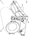
Figure 1 is a perspective view of an embodiment of a chamber in accordance with the principles of the present invention as installed on a hyperbaric and/or hypoxic chamber system. -
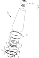
Figure 2 is an exploded perspective view of the chamber ofFig. 1 . -
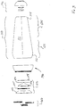
Figure 3 is an exploded side view of the chamber ofFig. 1 . -
Figure 4 is a cross-sectional side view of the tubular body of the chamber ofFig. 1 . -
Figure 5 is a front view of the tubular body of the chamber ofFig. 1 . -
Figure 6 is an exploded perspective view of the first end member of the chamber ofFig. 1 . -
Figure 7 is a cross cross-sectional side view of the first end member of the chamber ofFig. 1 . -
Figure 8 is an exploded perspective view of the second end member of the chamber ofFig. 1 . -
Figure 9 is a cross cross-sectional side view of the second end member of the chamber ofFig. 1 . -
Figure 10 is a perspective view of the chamber ofFig. 1 , in collapsed configuration. -
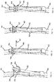
Figure 11 is a first perspective fragmentary view of a portion of the locking ring assembly of the chamber ofFig. 1 , during the locking procedure. -
Figure 12 is a second perspective fragmentary view of a portion of the locking ring assembly of the chamber ofFig. 1 , during the locking procedure. -
Figure 13 is a third perspective fragmentary view of a portion of the locking ring assembly of the chamber ofFig. 1 , during the locking procedure. -
Figure 14 is a fourth perspective fragmentary view of a portion of the locking ring assembly of the chamber ofFig. 1 , during the locking procedure. - A novel portable chamber for hyperbaric and/or hypoxic treatment will be described hereinafter. Although the invention is described in terms of specific illustrative embodiments, it is to be understood that the embodiments described herein are by way of example only and that the scope of the invention is not intended to be limited thereby.
- Referring now to the drawings, and more particularly to
Fig. 1 , a portable hyperbaric and/orhypoxic chamber system 10, comprising achamber 100 in accordance with the principles of the present invention, is illustrated. - The
chamber system 10 comprises achamber 100 suitable for hyperbaric and hypoxic treatments, as well as various sources (not shown) of gases (e.g. air, oxygen, etc.) to modify the conditions of air inside thechamber 100 with respect to the ambient conditions outside thechamber 100. These various sources, which typically include a pressure generator, a hypoxic generator and an oxygen source, are preferably, though not necessarily, all incorporated into the supportingstructure 200 which supports thechamber 100 during treatment, and are in fluid communication with the interior of thechamber 100 via appropriate pipes, valves, inlets and outlets (not shown). These sources are also typically controlled by acontrol system 300, which can include a console. Thecontrol system 300 is operatively connected to the various sources such as to control the conditions within thechamber 100 during hyperbaric or hypoxic treatment. Thecontrol system 300 could also be operatively connected to diverse sensors located inside thechamber 100 and/or on the user undergoing a treatment to monitor the conditions inside the chamber 100 (e.g. ambient pressure, ambient oxygen level, etc.) and/or the conditions of the user (e.g. heartbeat, oxygen level in the blood, etc.). Such supportingstructure 200 andcontrol system 300 are known in the art (see for instanceWO 2008/014617 ) and need not be described any further. - Still referring to
Fig. 1 , thechamber 100 is typically sized to accommodate at least one user or occupant that will undergo a hyperbaric or a hypoxic treatment. - Referring to
Figs. 2 and3 , in the present embodiment, thechamber 100 comprises an open-endedtubular body 110, afirst end member 140 and asecond end member 170. - As it will be explained below, the
first end member 140 and thesecond end member 170 are configured to be respectively mounted inside thetubular body 110 at thefirst extremity 112 and at thesecond extremity 114 thereof. Theend members chamber 100 is supplied with gases and thus pressurized, theend members second extremities tubular body 110, thereby sealing thechamber 100. - Referring now to each composing elements of the
chamber 100, and starting with thetubular body 110, as best illustrated inFigs. 2-4 , thetubular body 110 is typically of frustro-conical configuration. In that sense, the first orproximal extremity 112 has a generally larger diameter than the second ordistal extremity 114. As the skilled addressee will understand, thefirst extremity 112, and itsadjacent region 122, typically accommodate the upper portion (e.g. head and torso) of the body of the user while thesecond extremity 114, and itsadjacent region 124, typically accommodate the lower portion (e.g. legs and feet) of the body of the user. - As best shown in
Fig. 5 , thetubular body 110 typically has a circular cross-section. A circular cross-section is preferable to have a better distribution of pressure inside thetubular body 110. - The
tubular body 110 is made of a flexible and airtight reinforced elastomeric material. In the present embodiment, the elastomeric material is a latex-neoprene composition which is reinforced witharamid filaments 105 wound about thetubular body 110. - As best shown in
Fig. 4 , the reinforcingfilaments 105, only some of which are shown in phantom lines for clarity, are wound about thetubular body 110 at angle of approximately 54.7° (or -54.7°) with respect to thecentral axis 102. Though these angles are preferred, other angles are possible. - As the skilled addressee will understand, the winding of the
filaments 105 extends along thewhole length 103 of thetubular body 110. - Referring now to
Fig. 2 and more particularly toFigs. 3 and4 , thefirst extremity 112 and thesecond extremity 114 of thetubular body 110 are substantially of spherical configuration and they each comprise an opening. - The
first extremity 112 therefore has a first radius ofcurvature 113 and afirst opening 116 having afirst diameter 117 while thesecond extremity 114 has a second radius ofcurvature 115, smaller than thefirst radius 113, and asecond opening 118 having asecond diameter 119. - In the present embodiment, the first and
second diameters filaments 105 can be wound until the edges of the first and second openings. - Considering that the
chamber 100 will be used for hyperbaric purposes, the material of thetubular body 110 is designed to be able to sustain positive relative pressures, typically up to 180 psig, without bursting. Under positive relative pressures, thechamber 100 will typically structurally maintain its shape. - Still, despite being made of reinforced elastomeric material, the
tubular body 110 is flexible enough such that it can be collapsed as shown inFig. 10 . In such a collapsed condition, the wall 111 of thetubular body 110 is rolled or folded until thesecond end member 170 is nested in thefirst end member 140. In such a compact collapsed condition, thechamber 100 can be more easily transported and/or stored. In that regard, having atubular body 110 of frustro-conical shape is particularly advantageous since it allows thelarger extremity 112, and itsadjacent region 122, to easily receive thesmaller extremity 114 and itsadjacent region 124. - Referring now to
Figs. 2-3 and6-7 , thefirst end member 140 is shown in more details. Thefirst end member 140 is typically larger than thesecond end member 170 and is configured to be mounted for cooperation with thefirst extremity 112 of thetubular body 110. - In the present embodiment, the
end member 140 comprises an outer shell made of a fiberglass/epoxy composition, the shell having a polymeric foam core. The materials from which theend member 140 is made are preferably light such as to keep the overall weight of thechamber 100 low. - The
first end member 140 comprises afirst portion 142 which is located substantially inside thetubular body 110 during use, and asecond portion 144 which extends outside of thetubular body 110 during use. - The
first portion 142 defines a firstexterior surface 146 which is substantially spherical in configuration. In that sense, the firstexterior surface 146 generally has a radius ofcurvature 147 which is substantially equal to the radius ofcurvature 113 of thefirst extremity 112 of thetubular body 110. It is to be understood that the firstexterior surface 146 is configured to engage theinterior surface 123 of thefirst extremity 112 of thetubular body 110. It is thus important that the exterior shape of thefirst portion 142 of thefirst end member 140 generally matches the interior shape of thefirst extremity 112 of thetubular body 110 to prevent leaks when thechamber 100 is supplied with gases. - It is to be understood that in accordance with the principles of the present invention, there is no additional seal assembly between the
first end member 140 and thefirst extremity 112 of thetubular body 110. In the end, thechamber 100 is ultimately sealed by the interaction between the firstexterior surface 146 of thefirst end member 140 and theinterior surface 123 of thefirst extremity 112 as thefirst end member 140 is urged axially under pressure. - The
second portion 144, which extends from thefirst portion 142, comprises a radially extending lip orrim 148. Therim 148 is configured to cooperate with a lockingring assembly 160 to hold and lock the door assembly 150 in place. - Referring to
Figs. 2 to 4 , the door assembly 150 comprises a mainannular member 152 having anouter edge 151, acentral opening 153, and aninner edge 154. - Referring more particularly to
Fig. 7 , afirst ring 155 is secured (e.g. glued) to theinner edge 154 of themain member 152. Further mounted to thefirst ring 155 is awindow 156 which is secured thereto by a second ring 158 fastened (e.g. bolted, screwed) to thefirst ring 155. Aring seal 157 is further located between the second ring 158 and the edge of thewindow 156 to prevent leaks. - As best shown in
Fig. 7 , in the present embodiment, thewindow 156 is shaped as an inward dome (i.e. a dome extending toward the interior of the chamber 100). Similarly, the shape of themain member 152 is substantially arcuate. Hence, the overall configuration of themain member 152 and of thewindow 156, i.e. of the door assembly 150, is inwardly domed. This allows the door assembly 150 to sustain higher pressure without breaking. - Though not shown, the door assembly 150 could be advantageously provided with one or more handles to ease its manipulation.
- As already introduced above, the door assembly 150 is configured to be secured to the
second portion 144 of thefirst end member 140 with the aid of the lockingring assembly 160. In that sense, as best shown inFig. 7 , the door assembly 150 and thesecond portion 144 are configured such that theouter edge 151 of themain member 152 rests adjacent to theradial rim 148. - Referring now to
Figs. 2 ,3 and7 , in the present embodiment, the lockingring assembly 160 comprises afirst half ring 161 and asecond half ring 162. Both the first and the second half rings 161 and 162 have U-shaped cross-sections as best illustrated inFig. 7 . These U-shaped cross-sections serve to receive theradial rim 148 and theouter edge 151 of themain member 152 in a clamping arrangement. - Referring to
Figs. 2 and6 , two threadedrods 163 are pivotally mounted tohalf ring 162. Mounted to each of the threadedrods 163 is a threadedknob 164. - Referring to
Figs. 2 ,6 and11-14 , to receive therods 163 and theknobs 164,half ring 161 comprises two recessedportions 165, each having a flattop surface 166 and atransverse locking pin 167. - Referring now more particularly to
Figs. 11 to 14 , in use, once the door assembly 150 is properly mounted to thefirst end member 140, i.e. theouter edge 151 being located adjacent to theradial rim 148, the first and second half rings 161 and 162 are mounted to theradial rim 148 and to theouter edge 151 of themain member 152 such as to fully circumscribe them. Then, to lock both half rings 161 and 162 together, therods 163 are pivoted such as to come resting in the recessedportions 165 ofhalf ring 161. Then, to prevent accidental exit of therods 163 from the recessedportions 165, lockingpins 167 are inserted transversally in the recessedportions 165 as shown inFig. 12 . Then, as shown inFig. 13 , theknobs 164 of bothrods 163 are threaded down until abutment with thetop surfaces 166 of the recessedportions 165. Finally, theknobs 164 of bothrods 163 are further threaded down until thegap 169 between both half rings 161 and 162 is closed, thereby clamping both half rings 161 and 162 together and effectively locking the door assembly 150. - The remove the door assembly 150 from the
first end member 140, the above procedure is substantially done in a reverse order. - In the present embodiment, each
rod 163 is provided, at its free extremity, with a blockingelement 168 such as, but not limited to, a safety screw with a transverse cotter pin, to prevent theknob 164 to be unscrewed beyond a predetermined point. - The skilled addressee will understand that the locking
ring assembly 160 prevents accidental removal of the door assembly 150 even is one or bothknobs 164 are accidentally unscrewed during a hyperbaric or a hypoxic treatment. Indeed, as long as therods 163 are held and retained in their respective recessedportions 165 by the locking pins 167, both half rings 161 and 162 will remain attached together and will substantially circumscribe the door assembly 150. - The locking
ring assembly 160 thus also adds a layer of safety to the operation of thechamber 100. - Referring now to
Figs. 2-3 and8-9 , thesecond end member 170 is shown in more details. As the skilled addressee will understand, thesecond end member 170 is typically smaller than thefirst end member 140 since it is configured to be mounted for cooperation with the second, and smaller,extremity 114 of thetubular body 110. - In the present embodiment, the
second end member 170 comprises an outer shell made of a fiberglass/epoxy composition, the shell having a polymeric foam core. The materials from which thesecond end member 170 is made are preferably light such as to keep the overall weight of thechamber 100 low. - Typically, the
second end member 170 is made of the same materials as thefirst end member 140. - The
second end member 170 comprises afirst portion 172 which is located substantially inside thetubular body 110 during use, and asecond portion 174 which extends outside of thetubular body 110 during use. - The
first portion 172 defines a secondexterior surface 176 which is substantially spherical in configuration. In that sense, the secondexterior surface 176 generally has a radius of curvature 177 which is substantially equal to the radius ofcurvature 115 of thesecond extremity 114 of thetubular body 110. It is to be understood that the secondexterior surface 176 is configured to engage theinterior surface 125 of thesecond extremity 114 of thetubular body 110. It is thus important that the exterior shape of thefirst portion 172 of thesecond end member 170 generally matches the interior shape of thesecond extremity 114 of thetubular body 110 to prevent leaks when thechamber 100 is supplied with gases. - Again, it is to be understood that in accordance with the principles of the present invention, as for the
first end member 140, there is no additional seal assembly between thesecond end member 170 and thesecond extremity 114 of thetubular body 110. In the end, thechamber 100 is ultimately sealed by the interaction between the secondexterior surface 176 of thesecond end member 170 and theinterior surface 125 of thesecond extremity 114 as thesecond end member 170 is urged axially under pressure. - The
second portion 174, which extends from thefirst portion 172, comprises a central opening 178 having aninner edge 179. - As shown in
Fig. 9 , afirst ring 180 is secured (e.g. glued) to theinner edge 179 of the central opening 178. Mounted to thefirst ring 180 is a window 181 which is secured thereto by asecond ring 183 fastened (e.g. bolted, screwed) to thefirst ring 180. Aring seal 182 is further located between thesecond ring 183 and the edge of the window 181 to prevent leaks. - As best shown in
Fig. 9 , in the present embodiment, the window 181 is shaped as an inward dome such as to allow the window 181 to sustain higher pressure without breaking. - In the normal assembled configuration of the
chamber 100, thefirst portion 142 of thefirst end member 140 is mounted inside thetubular body 110 for engagement with thefirst extremity 112, and thefirst portion 172 of thesecond end member 170 is mounted inside thetubular body 110 for engagement with thesecond extremity 114. - In used, as the
chamber 100 is supplied with gases during hyperbaric or hypoxic treatments, the gases will respectively axially push or urge thefirst end member 140, with the door assembly 150 mounted thereto, against theinner surface 123 of thefirst extremity 112, and thesecond end member 170 against theinner surface 125 of thesecond extremity 114. The engagement of theend members extremities chamber 100 without additional seal assembly. - Hence, a
chamber 100 in accordance with the principles of the present invention has a simpler configuration, is sturdy enough to sustain significant pressure (e.g. up to 12410.6 hPa (180 psig)), and is easily collapsible for storage and transport. - Though not shown, it is contemplated that the
chamber 100 be provided with a mattress to support the user lying in thechamber 100 for treatment. The mattress could comprise a hinged structure to allow the user to take a seated position within thechamber 100. In addition, the mattress (e.g., synthetic foam material or similar material that will not affect the oxygen level in the chamber 100) would preferably be shaped to as to be received in the bottom of thechamber 100. - Though not shown, it is further contemplated that the
chamber 100 be provided with handrails in order to facilitate movements inside thechamber 100 and/or to receive a stretcher (not shown). The handrails would preferably extend between the first andsecond end members - While illustrative and presently preferred embodiments of the invention have been described in detail hereinabove, it is to be understood that the inventive concepts may be otherwise variously embodied and employed and that the appended claims are intended to be construed to include such variations except insofar as limited by the prior art.
Claims (16)
- A chamber suitable for use with a portable hyperbaric and/or hypoxic chamber system, the chamber being connectable to at least one source of gases for receiving a supply of gases during a treatment, characterized in that the chamber comprises:a) an open-ended tubular body (110) sized to accommodate at least one occupant, the tubular body being made of a flexible and reinforced elastomeric material and comprising a first substantially spherical extremity (112) having a first radius of curvature (113) and comprising a first opening (116), a second substantially spherical extremity (114) having a second radius of curvature (115) and comprising a second opening (118). and a central axis (102);b) a first end member (140) configured to be mounted substantially inside the tubular body (110) at the first extremity (112) of the tubular body to close off the first extremity of the tubular body, the first end member comprising a first substantially spherical periphery having a third radius of curvature (147), the third radius of curvature being substantially equal to the first radius of curvature (113);c) a second end member (170) configured to be mounted substantially inside the tubular body (110) at the second extremity (114) of the tubular body to close off the second extremity of the tubular body, the second end member comprising a second substantially spherical periphery having a fourth radius of curvature (177), the fourth radius of curvature being substantially equal to the second radius of curvature (115);wherein at least one of the first and second end members comprises a door (150) for providing access to an interior of the tubular body; and
wherein when the chamber is supplied with gases, the first and second end members are respectively urged against the first and second extremities of the tubular body, thereby sealing the chamber. - A chamber as claimed in claim 1, wherein the tubular body has a frustro-conical configuration.
- A chamber as claimed in claim 2, wherein the first radius of curvature (113) is larger than the second radius of curvature (115).
- A chamber as claimed in claim 1, wherein the elastomeric material is a latex-neoprene composition.
- A chamber as claimed in claim 1, wherein the elastomeric material is reinforced with filaments wound (105) about the tubular body.
- A chamber as claimed in claim 5, wherein the filaments are made of aramid.
- A chamber as claimed in claim 5, wherein the filaments are wound about the tubular body at an angle with respect to the central axis (102).
- A chamber as claimed in claim 7, wherein the angle is approximately 54.7 degrees or approximately -54.7 degrees.
- A chamber as claimed in claim 1, wherein the door (150) is configured to be removably mounted to the first end member (140).
- A chamber as claimed in claim 1, characterized in that the chamber is a portable chamber anda) the tubular body is a frustro-conical tubular body sized to accommodate at least one occupant, the frustro-conical tubular body being made of a reinforced elastomeric material, the frustro-conical tubular body comprising a first substantially spherical extremity (112) having a first radius of curvature (113) and comprising a first opening (116), and a second substantially spherical extremity (114) having a second radius of curvature (115) and comprising a second opening (118), the first radius of curvature being larger than the second radius of curvature (102);b) the first end member (140) configured to be mounted substantially inside the frustro-conical tubular body (110) at the first extremity (112) to close off the first opening (116), the first end member comprising a first substantially spherical periphery having a third radius of curvature (147), the third radius of curvature being substantially equal to the first radius of curvature (113), the first end member comprising the door (150) for providing access to the interior of the tubular body;c) the second end member (170) configured to be mounted substantially inside the frustro-conical tubular body (110) at the second extremity (114) to close off the second opening (118), the second end member comprising the second substantially spherical periphery having the fourth radius of curvature (177), the fourth radius of curvature being substantially equal to the second radius of curvature (115);wherein when the chamber is supplied with gases, the first end member is urged against the first extremity of the tubular body such that the first spherical periphery engages an inner surface (123) of the first extremity, and the second end member is urged against the second extremity of the tubular body such that the second spherical periphery engages an inner surface (125) of the second extremity, thereby sealing the chamber.
- A chamber as claimed in claim 10, wherein the door (150) is secured to the first end member via a locking ring assembly (160).
- A chamber as claimed in claim 1, characterised in that the chamber is part of a hyperbaric and/or hypoxic chamber system comprising said chamber connected to at least one source of gases.
- A chamber system as claimed in claim 12, wherein the tubular body has a frustro-conical configuration.
- A chamber system as claimed in claim 12, further comprising a control system (300) operatively connected to the at least one source of gases for controlling the supply of the gases to the chamber.
- A chamber system as claimed in any of claims 12 to 14, further comprising a support structure (200) for supporting the chamber.
- A chamber system as claimed in claim 15, wherein the at least one source of gases is incorporated into the support structure (200).
Applications Claiming Priority (1)
| Application Number | Priority Date | Filing Date | Title |
|---|---|---|---|
| PCT/CA2010/001697 WO2012055003A1 (en) | 2010-10-27 | 2010-10-27 | Portable chamber for hyperbaric and/or hypoxic treatment |
Publications (3)
| Publication Number | Publication Date |
|---|---|
| EP2632409A1 EP2632409A1 (en) | 2013-09-04 |
| EP2632409A4 EP2632409A4 (en) | 2015-09-23 |
| EP2632409B1 true EP2632409B1 (en) | 2017-05-24 |
Family
ID=45992990
Family Applications (1)
| Application Number | Title | Priority Date | Filing Date |
|---|---|---|---|
| EP10858790.8A Not-in-force EP2632409B1 (en) | 2010-10-27 | 2010-10-27 | Portable chamber for hyperbaric and/or hypoxic treatment |
Country Status (7)
| Country | Link |
|---|---|
| US (1) | US9649238B2 (en) |
| EP (1) | EP2632409B1 (en) |
| JP (1) | JP2013540537A (en) |
| CN (1) | CN103354739B (en) |
| BR (1) | BR112013010217A2 (en) |
| CA (1) | CA2845398C (en) |
| WO (1) | WO2012055003A1 (en) |
Families Citing this family (8)
| Publication number | Priority date | Publication date | Assignee | Title |
|---|---|---|---|---|
| CZ305989B6 (en) | 2014-11-21 | 2016-06-08 | Univerzita Palackého | Mobile hyperbaric minichamber |
| KR101752744B1 (en) | 2015-08-27 | 2017-07-14 | 주식회사 옥시캡플러스 | A chamber for hyperbaric oxygen treatment |
| KR101752747B1 (en) | 2015-08-27 | 2017-07-14 | 주식회사 옥시캡플러스 | A chamber for hyperbaric oxygen treatment |
| CN106236461A (en) * | 2016-08-23 | 2016-12-21 | 中国人民解放军第七医院 | Assembled barochamber |
| JP6930837B2 (en) * | 2017-01-23 | 2021-09-01 | Gmoインターネット株式会社 | Environment simulation device |
| USD958371S1 (en) * | 2020-11-25 | 2022-07-19 | Frederick E Ryder | Split hyperbaric chamber |
| AU2022323665A1 (en) * | 2021-08-02 | 2024-02-29 | Bariks Health Ltd | Foldable inflatable hyperbaric chamber |
| CN119302817B (en) * | 2024-12-13 | 2025-03-07 | 内蒙古科技大学包头医学院 | Adjustable hypoxia training equipment for highland hypoxia training |
Family Cites Families (15)
| Publication number | Priority date | Publication date | Assignee | Title |
|---|---|---|---|---|
| US3877427A (en) * | 1972-05-25 | 1975-04-15 | Semen Mikhailovich Alexeev | Oxygen compressive chamber |
| US4974829A (en) * | 1985-06-10 | 1990-12-04 | Portable Hyperbarics, Inc. | Hyperbaric chamber |
| GB2190595B (en) * | 1986-05-21 | 1990-02-21 | Paracel Holdings Pty Ltd | Recompression chamber |
| CN1032624A (en) * | 1988-11-19 | 1989-05-03 | 董国臣 | Hyperbaric negative oxygen ion chamber |
| GB8901840D0 (en) * | 1989-01-27 | 1989-03-15 | Courtaulds Plc | Pressure vessels |
| IT1275924B1 (en) * | 1995-03-16 | 1997-10-24 | Gse Giunio Santi Engineering S | FLEXIBLE HULL LIFE-HYBRIC CHAMBER |
| GB2302810B (en) * | 1995-07-05 | 1999-06-16 | Lakeside Eng Ltd | Variable pressure chamber |
| US5678722A (en) * | 1996-03-15 | 1997-10-21 | Reneau; Raymond Paul | Pressure chamber |
| US6443148B1 (en) * | 1998-07-28 | 2002-09-03 | Hyperbaric Management Systems, Inc. | Hyperbaric oxygen therapy system |
| GB9926514D0 (en) * | 1999-11-10 | 2000-01-12 | Burnup Alex | Pressure vessel |
| US6321746B1 (en) * | 2000-05-17 | 2001-11-27 | The United States Of America As Represented By The Administrator Of The National Aeronautics And Space Adminstration | Portable hyperbaric chamber |
| JP2007044194A (en) * | 2005-08-09 | 2007-02-22 | Tono Craft Kk | Air pressure adjustment module |
| WO2008014617A1 (en) * | 2006-08-04 | 2008-02-07 | Hemato Max | Hyperbaric/hypoxic chamber system |
| EP2217317B1 (en) * | 2007-11-06 | 2015-03-04 | AOTI Limited | Hyperbaric wound treatment device |
| CN201197786Y (en) * | 2008-04-19 | 2009-02-25 | 烟台冰轮高压氧舱有限公司 | Hyperbaric oxygen chamber with top door |
-
2010
- 2010-10-27 EP EP10858790.8A patent/EP2632409B1/en not_active Not-in-force
- 2010-10-27 JP JP2013535212A patent/JP2013540537A/en active Pending
- 2010-10-27 BR BR112013010217A patent/BR112013010217A2/en not_active Application Discontinuation
- 2010-10-27 CN CN201080070974.7A patent/CN103354739B/en not_active Expired - Fee Related
- 2010-10-27 US US13/881,814 patent/US9649238B2/en not_active Expired - Fee Related
- 2010-10-27 CA CA2845398A patent/CA2845398C/en not_active Expired - Fee Related
- 2010-10-27 WO PCT/CA2010/001697 patent/WO2012055003A1/en not_active Ceased
Also Published As
| Publication number | Publication date |
|---|---|
| BR112013010217A2 (en) | 2018-07-10 |
| EP2632409A1 (en) | 2013-09-04 |
| US9649238B2 (en) | 2017-05-16 |
| CN103354739A (en) | 2013-10-16 |
| CA2845398C (en) | 2015-05-26 |
| CA2845398A1 (en) | 2012-05-03 |
| US20130206146A1 (en) | 2013-08-15 |
| JP2013540537A (en) | 2013-11-07 |
| EP2632409A4 (en) | 2015-09-23 |
| CN103354739B (en) | 2017-08-15 |
| WO2012055003A1 (en) | 2012-05-03 |
Similar Documents
| Publication | Publication Date | Title |
|---|---|---|
| CA2845398C (en) | Portable chamber for hyperbaric and/or hypoxic treatment | |
| US8375938B2 (en) | Hyperbaric/hypoxic chamber system | |
| CA2715278C (en) | Hyperbaric chamber | |
| US5738093A (en) | Flexible hyperbaric chamber | |
| US5806878A (en) | Collapsible wheelbarrow/stretcher | |
| US9622931B2 (en) | Portable hyperbaric chamber with a vertical mounting system | |
| JP2009542344A (en) | High pressure chamber | |
| JP2013540537A5 (en) | Transportable chamber for high pressure and / or hypoxic therapy, method of providing hypoxic therapy to a user using the chamber, and high pressure chamber and / or hypoxic chamber system | |
| CA1302775C (en) | Recompression chamber | |
| US20200263821A1 (en) | Inversion Unit With Expandable Carrying Handles And Removable Wheelbase | |
| US8905027B2 (en) | Portable compression chambers | |
| KR20240040803A (en) | Collapsible injection hyperbaric chamber | |
| RU2294187C2 (en) | Transformable altitude chamber | |
| WO2025097161A1 (en) | Apparatus, systems, and methods for hyperbaric thermoregulated medical evacuation pod | |
| WO2014044750A2 (en) | Hyperbaric chambers | |
| KR20230158704A (en) | Portable liquefied oxygen containers made of double bulkheads | |
| US11766516B2 (en) | Vacuum assisted drainage reservoir and systems | |
| TWI446899B (en) | Tissue engineering device | |
| CN208031252U (en) | The pneumatic tourniquet of operation tape relay head | |
| ES1193187U (en) | Portable hyperbaric chamber (Machine-translation by Google Translate, not legally binding) | |
| GB2564403A (en) | Canister device for producing sclerosing foam |
Legal Events
| Date | Code | Title | Description |
|---|---|---|---|
| PUAI | Public reference made under article 153(3) epc to a published international application that has entered the european phase |
Free format text: ORIGINAL CODE: 0009012 |
|
| 17P | Request for examination filed |
Effective date: 20130527 |
|
| AK | Designated contracting states |
Kind code of ref document: A1 Designated state(s): AL AT BE BG CH CY CZ DE DK EE ES FI FR GB GR HR HU IE IS IT LI LT LU LV MC MK MT NL NO PL PT RO RS SE SI SK SM TR |
|
| DAX | Request for extension of the european patent (deleted) | ||
| RA4 | Supplementary search report drawn up and despatched (corrected) |
Effective date: 20150825 |
|
| RIC1 | Information provided on ipc code assigned before grant |
Ipc: A61G 10/02 20060101AFI20150819BHEP Ipc: B63C 11/32 20060101ALI20150819BHEP |
|
| GRAP | Despatch of communication of intention to grant a patent |
Free format text: ORIGINAL CODE: EPIDOSNIGR1 |
|
| RIC1 | Information provided on ipc code assigned before grant |
Ipc: A61G 10/02 20060101AFI20161102BHEP Ipc: B63C 11/32 20060101ALI20161102BHEP |
|
| INTG | Intention to grant announced |
Effective date: 20161202 |
|
| GRAS | Grant fee paid |
Free format text: ORIGINAL CODE: EPIDOSNIGR3 |
|
| GRAA | (expected) grant |
Free format text: ORIGINAL CODE: 0009210 |
|
| AK | Designated contracting states |
Kind code of ref document: B1 Designated state(s): AL AT BE BG CH CY CZ DE DK EE ES FI FR GB GR HR HU IE IS IT LI LT LU LV MC MK MT NL NO PL PT RO RS SE SI SK SM TR |
|
| REG | Reference to a national code |
Ref country code: GB Ref legal event code: FG4D |
|
| REG | Reference to a national code |
Ref country code: CH Ref legal event code: EP |
|
| REG | Reference to a national code |
Ref country code: IE Ref legal event code: FG4D |
|
| REG | Reference to a national code |
Ref country code: AT Ref legal event code: REF Ref document number: 895643 Country of ref document: AT Kind code of ref document: T Effective date: 20170615 |
|
| REG | Reference to a national code |
Ref country code: DE Ref legal event code: R096 Ref document number: 602010042604 Country of ref document: DE |
|
| REG | Reference to a national code |
Ref country code: NL Ref legal event code: MP Effective date: 20170524 |
|
| REG | Reference to a national code |
Ref country code: LT Ref legal event code: MG4D |
|
| REG | Reference to a national code |
Ref country code: AT Ref legal event code: MK05 Ref document number: 895643 Country of ref document: AT Kind code of ref document: T Effective date: 20170524 |
|
| PG25 | Lapsed in a contracting state [announced via postgrant information from national office to epo] |
Ref country code: NO Free format text: LAPSE BECAUSE OF FAILURE TO SUBMIT A TRANSLATION OF THE DESCRIPTION OR TO PAY THE FEE WITHIN THE PRESCRIBED TIME-LIMIT Effective date: 20170824 Ref country code: HR Free format text: LAPSE BECAUSE OF FAILURE TO SUBMIT A TRANSLATION OF THE DESCRIPTION OR TO PAY THE FEE WITHIN THE PRESCRIBED TIME-LIMIT Effective date: 20170524 Ref country code: GR Free format text: LAPSE BECAUSE OF FAILURE TO SUBMIT A TRANSLATION OF THE DESCRIPTION OR TO PAY THE FEE WITHIN THE PRESCRIBED TIME-LIMIT Effective date: 20170825 Ref country code: ES Free format text: LAPSE BECAUSE OF FAILURE TO SUBMIT A TRANSLATION OF THE DESCRIPTION OR TO PAY THE FEE WITHIN THE PRESCRIBED TIME-LIMIT Effective date: 20170524 Ref country code: AT Free format text: LAPSE BECAUSE OF FAILURE TO SUBMIT A TRANSLATION OF THE DESCRIPTION OR TO PAY THE FEE WITHIN THE PRESCRIBED TIME-LIMIT Effective date: 20170524 Ref country code: FI Free format text: LAPSE BECAUSE OF FAILURE TO SUBMIT A TRANSLATION OF THE DESCRIPTION OR TO PAY THE FEE WITHIN THE PRESCRIBED TIME-LIMIT Effective date: 20170524 Ref country code: LT Free format text: LAPSE BECAUSE OF FAILURE TO SUBMIT A TRANSLATION OF THE DESCRIPTION OR TO PAY THE FEE WITHIN THE PRESCRIBED TIME-LIMIT Effective date: 20170524 |
|
| PG25 | Lapsed in a contracting state [announced via postgrant information from national office to epo] |
Ref country code: IS Free format text: LAPSE BECAUSE OF FAILURE TO SUBMIT A TRANSLATION OF THE DESCRIPTION OR TO PAY THE FEE WITHIN THE PRESCRIBED TIME-LIMIT Effective date: 20170924 Ref country code: RS Free format text: LAPSE BECAUSE OF FAILURE TO SUBMIT A TRANSLATION OF THE DESCRIPTION OR TO PAY THE FEE WITHIN THE PRESCRIBED TIME-LIMIT Effective date: 20170524 Ref country code: BG Free format text: LAPSE BECAUSE OF FAILURE TO SUBMIT A TRANSLATION OF THE DESCRIPTION OR TO PAY THE FEE WITHIN THE PRESCRIBED TIME-LIMIT Effective date: 20170824 Ref country code: NL Free format text: LAPSE BECAUSE OF FAILURE TO SUBMIT A TRANSLATION OF THE DESCRIPTION OR TO PAY THE FEE WITHIN THE PRESCRIBED TIME-LIMIT Effective date: 20170524 Ref country code: LV Free format text: LAPSE BECAUSE OF FAILURE TO SUBMIT A TRANSLATION OF THE DESCRIPTION OR TO PAY THE FEE WITHIN THE PRESCRIBED TIME-LIMIT Effective date: 20170524 Ref country code: SE Free format text: LAPSE BECAUSE OF FAILURE TO SUBMIT A TRANSLATION OF THE DESCRIPTION OR TO PAY THE FEE WITHIN THE PRESCRIBED TIME-LIMIT Effective date: 20170524 |
|
| PG25 | Lapsed in a contracting state [announced via postgrant information from national office to epo] |
Ref country code: CZ Free format text: LAPSE BECAUSE OF FAILURE TO SUBMIT A TRANSLATION OF THE DESCRIPTION OR TO PAY THE FEE WITHIN THE PRESCRIBED TIME-LIMIT Effective date: 20170524 Ref country code: RO Free format text: LAPSE BECAUSE OF FAILURE TO SUBMIT A TRANSLATION OF THE DESCRIPTION OR TO PAY THE FEE WITHIN THE PRESCRIBED TIME-LIMIT Effective date: 20170524 Ref country code: DK Free format text: LAPSE BECAUSE OF FAILURE TO SUBMIT A TRANSLATION OF THE DESCRIPTION OR TO PAY THE FEE WITHIN THE PRESCRIBED TIME-LIMIT Effective date: 20170524 Ref country code: SK Free format text: LAPSE BECAUSE OF FAILURE TO SUBMIT A TRANSLATION OF THE DESCRIPTION OR TO PAY THE FEE WITHIN THE PRESCRIBED TIME-LIMIT Effective date: 20170524 Ref country code: EE Free format text: LAPSE BECAUSE OF FAILURE TO SUBMIT A TRANSLATION OF THE DESCRIPTION OR TO PAY THE FEE WITHIN THE PRESCRIBED TIME-LIMIT Effective date: 20170524 |
|
| REG | Reference to a national code |
Ref country code: DE Ref legal event code: R097 Ref document number: 602010042604 Country of ref document: DE |
|
| PG25 | Lapsed in a contracting state [announced via postgrant information from national office to epo] |
Ref country code: SM Free format text: LAPSE BECAUSE OF FAILURE TO SUBMIT A TRANSLATION OF THE DESCRIPTION OR TO PAY THE FEE WITHIN THE PRESCRIBED TIME-LIMIT Effective date: 20170524 Ref country code: PL Free format text: LAPSE BECAUSE OF FAILURE TO SUBMIT A TRANSLATION OF THE DESCRIPTION OR TO PAY THE FEE WITHIN THE PRESCRIBED TIME-LIMIT Effective date: 20170524 Ref country code: IT Free format text: LAPSE BECAUSE OF FAILURE TO SUBMIT A TRANSLATION OF THE DESCRIPTION OR TO PAY THE FEE WITHIN THE PRESCRIBED TIME-LIMIT Effective date: 20170524 |
|
| PLBE | No opposition filed within time limit |
Free format text: ORIGINAL CODE: 0009261 |
|
| STAA | Information on the status of an ep patent application or granted ep patent |
Free format text: STATUS: NO OPPOSITION FILED WITHIN TIME LIMIT |
|
| 26N | No opposition filed |
Effective date: 20180227 |
|
| PG25 | Lapsed in a contracting state [announced via postgrant information from national office to epo] |
Ref country code: SI Free format text: LAPSE BECAUSE OF FAILURE TO SUBMIT A TRANSLATION OF THE DESCRIPTION OR TO PAY THE FEE WITHIN THE PRESCRIBED TIME-LIMIT Effective date: 20170524 Ref country code: MC Free format text: LAPSE BECAUSE OF FAILURE TO SUBMIT A TRANSLATION OF THE DESCRIPTION OR TO PAY THE FEE WITHIN THE PRESCRIBED TIME-LIMIT Effective date: 20170524 |
|
| REG | Reference to a national code |
Ref country code: CH Ref legal event code: PL |
|
| REG | Reference to a national code |
Ref country code: IE Ref legal event code: MM4A |
|
| REG | Reference to a national code |
Ref country code: FR Ref legal event code: ST Effective date: 20180629 |
|
| PG25 | Lapsed in a contracting state [announced via postgrant information from national office to epo] |
Ref country code: LU Free format text: LAPSE BECAUSE OF NON-PAYMENT OF DUE FEES Effective date: 20171027 Ref country code: LI Free format text: LAPSE BECAUSE OF NON-PAYMENT OF DUE FEES Effective date: 20171031 Ref country code: CH Free format text: LAPSE BECAUSE OF NON-PAYMENT OF DUE FEES Effective date: 20171031 |
|
| REG | Reference to a national code |
Ref country code: BE Ref legal event code: MM Effective date: 20171031 |
|
| PG25 | Lapsed in a contracting state [announced via postgrant information from national office to epo] |
Ref country code: FR Free format text: LAPSE BECAUSE OF NON-PAYMENT OF DUE FEES Effective date: 20171031 Ref country code: BE Free format text: LAPSE BECAUSE OF NON-PAYMENT OF DUE FEES Effective date: 20171031 |
|
| PG25 | Lapsed in a contracting state [announced via postgrant information from national office to epo] |
Ref country code: MT Free format text: LAPSE BECAUSE OF NON-PAYMENT OF DUE FEES Effective date: 20171027 |
|
| PG25 | Lapsed in a contracting state [announced via postgrant information from national office to epo] |
Ref country code: IE Free format text: LAPSE BECAUSE OF NON-PAYMENT OF DUE FEES Effective date: 20171027 |
|
| PG25 | Lapsed in a contracting state [announced via postgrant information from national office to epo] |
Ref country code: HU Free format text: LAPSE BECAUSE OF FAILURE TO SUBMIT A TRANSLATION OF THE DESCRIPTION OR TO PAY THE FEE WITHIN THE PRESCRIBED TIME-LIMIT; INVALID AB INITIO Effective date: 20101027 |
|
| PG25 | Lapsed in a contracting state [announced via postgrant information from national office to epo] |
Ref country code: CY Free format text: LAPSE BECAUSE OF NON-PAYMENT OF DUE FEES Effective date: 20170524 |
|
| PG25 | Lapsed in a contracting state [announced via postgrant information from national office to epo] |
Ref country code: MK Free format text: LAPSE BECAUSE OF FAILURE TO SUBMIT A TRANSLATION OF THE DESCRIPTION OR TO PAY THE FEE WITHIN THE PRESCRIBED TIME-LIMIT Effective date: 20170524 |
|
| PGFP | Annual fee paid to national office [announced via postgrant information from national office to epo] |
Ref country code: DE Payment date: 20191030 Year of fee payment: 10 |
|
| PG25 | Lapsed in a contracting state [announced via postgrant information from national office to epo] |
Ref country code: TR Free format text: LAPSE BECAUSE OF FAILURE TO SUBMIT A TRANSLATION OF THE DESCRIPTION OR TO PAY THE FEE WITHIN THE PRESCRIBED TIME-LIMIT Effective date: 20170524 |
|
| PG25 | Lapsed in a contracting state [announced via postgrant information from national office to epo] |
Ref country code: PT Free format text: LAPSE BECAUSE OF FAILURE TO SUBMIT A TRANSLATION OF THE DESCRIPTION OR TO PAY THE FEE WITHIN THE PRESCRIBED TIME-LIMIT Effective date: 20170524 |
|
| PG25 | Lapsed in a contracting state [announced via postgrant information from national office to epo] |
Ref country code: AL Free format text: LAPSE BECAUSE OF FAILURE TO SUBMIT A TRANSLATION OF THE DESCRIPTION OR TO PAY THE FEE WITHIN THE PRESCRIBED TIME-LIMIT Effective date: 20170524 |
|
| REG | Reference to a national code |
Ref country code: DE Ref legal event code: R119 Ref document number: 602010042604 Country of ref document: DE |
|
| PG25 | Lapsed in a contracting state [announced via postgrant information from national office to epo] |
Ref country code: DE Free format text: LAPSE BECAUSE OF NON-PAYMENT OF DUE FEES Effective date: 20210501 |
|
| PGFP | Annual fee paid to national office [announced via postgrant information from national office to epo] |
Ref country code: GB Payment date: 20211015 Year of fee payment: 12 |
|
| GBPC | Gb: european patent ceased through non-payment of renewal fee |
Effective date: 20221027 |
|
| PG25 | Lapsed in a contracting state [announced via postgrant information from national office to epo] |
Ref country code: GB Free format text: LAPSE BECAUSE OF NON-PAYMENT OF DUE FEES Effective date: 20221027 |