EP2632382B2 - Navigationsaufsatz für optische geräte in der medizin und verfahren - Google Patents
Navigationsaufsatz für optische geräte in der medizin und verfahren Download PDFInfo
- Publication number
- EP2632382B2 EP2632382B2 EP11778578.2A EP11778578A EP2632382B2 EP 2632382 B2 EP2632382 B2 EP 2632382B2 EP 11778578 A EP11778578 A EP 11778578A EP 2632382 B2 EP2632382 B2 EP 2632382B2
- Authority
- EP
- European Patent Office
- Prior art keywords
- image data
- optical device
- virtual image
- virtual
- body part
- Prior art date
- Legal status (The legal status is an assumption and is not a legal conclusion. Google has not performed a legal analysis and makes no representation as to the accuracy of the status listed.)
- Active
Links
Images

Classifications
-
- H—ELECTRICITY
- H04—ELECTRIC COMMUNICATION TECHNIQUE
- H04N—PICTORIAL COMMUNICATION, e.g. TELEVISION
- H04N7/00—Television systems
- H04N7/18—Closed-circuit television [CCTV] systems, i.e. systems in which the video signal is not broadcast
- H04N7/183—Closed-circuit television [CCTV] systems, i.e. systems in which the video signal is not broadcast for receiving images from a single remote source
-
- A—HUMAN NECESSITIES
- A61—MEDICAL OR VETERINARY SCIENCE; HYGIENE
- A61B—DIAGNOSIS; SURGERY; IDENTIFICATION
- A61B90/00—Instruments, implements or accessories specially adapted for surgery or diagnosis and not covered by any of the groups A61B1/00 - A61B50/00, e.g. for luxation treatment or for protecting wound edges
- A61B90/36—Image-producing devices or illumination devices not otherwise provided for
-
- A—HUMAN NECESSITIES
- A61—MEDICAL OR VETERINARY SCIENCE; HYGIENE
- A61B—DIAGNOSIS; SURGERY; IDENTIFICATION
- A61B17/00—Surgical instruments, devices or methods
- A61B17/00234—Surgical instruments, devices or methods for minimally invasive surgery
- A61B2017/00292—Surgical instruments, devices or methods for minimally invasive surgery mounted on or guided by flexible, e.g. catheter-like, means
- A61B2017/00296—Surgical instruments, devices or methods for minimally invasive surgery mounted on or guided by flexible, e.g. catheter-like, means mounted on an endoscope
-
- A—HUMAN NECESSITIES
- A61—MEDICAL OR VETERINARY SCIENCE; HYGIENE
- A61B—DIAGNOSIS; SURGERY; IDENTIFICATION
- A61B34/00—Computer-aided surgery; Manipulators or robots specially adapted for use in surgery
- A61B34/20—Surgical navigation systems; Devices for tracking or guiding surgical instruments, e.g. for frameless stereotaxis
- A61B2034/2046—Tracking techniques
- A61B2034/2051—Electromagnetic tracking systems
-
- A—HUMAN NECESSITIES
- A61—MEDICAL OR VETERINARY SCIENCE; HYGIENE
- A61B—DIAGNOSIS; SURGERY; IDENTIFICATION
- A61B90/00—Instruments, implements or accessories specially adapted for surgery or diagnosis and not covered by any of the groups A61B1/00 - A61B50/00, e.g. for luxation treatment or for protecting wound edges
- A61B90/36—Image-producing devices or illumination devices not otherwise provided for
- A61B90/361—Image-producing devices, e.g. surgical cameras
- A61B2090/3612—Image-producing devices, e.g. surgical cameras with images taken automatically
-
- A—HUMAN NECESSITIES
- A61—MEDICAL OR VETERINARY SCIENCE; HYGIENE
- A61B—DIAGNOSIS; SURGERY; IDENTIFICATION
- A61B90/00—Instruments, implements or accessories specially adapted for surgery or diagnosis and not covered by any of the groups A61B1/00 - A61B50/00, e.g. for luxation treatment or for protecting wound edges
- A61B90/36—Image-producing devices or illumination devices not otherwise provided for
- A61B2090/364—Correlation of different images or relation of image positions in respect to the body
- A61B2090/365—Correlation of different images or relation of image positions in respect to the body augmented reality, i.e. correlating a live optical image with another image
Definitions
- the invention relates to a method and a device for displaying image data, in which an optical device detects the position and thus position information is obtained and with the aid of the position information image data is determined and displayed or further processed.
- Position information here means the position and orientation of the optical device in relation to a reference coordinate system, i.e. a coordinate system of a position detection device.
- the position information can be recorded using a position detection device with a corresponding measuring system.
- Image data of the patient e.g. computer tomography images
- image data of the patient are often used as a basis for planning.
- the doctor works with a direct view of the surgical area.
- Optical visualization systems/optical devices such as an endoscope or microscope are available for this purpose.
- the doctor In order to implement his plan, the doctor must establish the link between the preoperative image data and the intraoperative visual information. This can lead to an increase in the duration of the operation or errors during the operation due to orientation problems.
- Medical navigation systems are known as orientation aids during surgery. These systems record the coordinate transformation between the patient and one or more instruments during surgery and visualize them in the preoperative planning data.
- the patient and instrument are equipped with localizers, the position and orientation of which are recorded by a measuring system as a position detection device.
- Electromagnetic, optical or ultrasound systems with corresponding sensors are used as measuring systems for a position detection device, as is also provided for the device according to the invention in certain embodiments.
- the device according to the invention can be designed accordingly. It can have corresponding devices for this.
- an optical aid such as an endoscope
- the navigation system thus records the position of the endoscope and the distance measuring device records the distance to a structure from a reference point on the endoscope.
- the combination of the two pieces of information allows the position of the contactlessly recorded measuring point to be calculated and displayed in the image data.
- coils with a soft iron core can be used as localizers in electromagnetic measuring systems with alternating fields.
- characteristic voltages are induced in the alternating field of the so-called field generator of the measuring system, from which the position of the coil in relation to the field generator can be determined. Since such coils are used as sensors in an electromagnetic measuring system for position detection, they are also called sensor coils.
- cross-sectional images from a volume data set are often used and the position is drawn into the slice as a point, cross, or similar.
- Three orthogonal slices are often displayed.
- the printed publication WO 2007/115825 A1 a method is described in which real image data are recorded by means of an optical device, the position and/or orientation of the optical device is simultaneously recorded and location information is derived therefrom, and the real image data recorded by the optical device are processed, taking into account the location information, to form virtual image data and/or image data to be displayed together with the virtual image data.
- the object of the invention is to provide a simple device for navigating an optical visualization device or an optical device and a method for registration and/or display of patient image data to this optical visualization device.
- this object is achieved on the one hand by a method for displaying image data according to claim 1, on the other hand by a device for displaying image data according to claim 8, and finally also by a medical treatment device according to claim 10, a digital storage medium according to claim 11, a computer program product according to claim 12 and a computer program according to claim 13.
- either virtual image data is generated from the real image data, for example a three-dimensional model of an object or body part is created from real image data, or real image data, i.e. image data captured by the optical device, is linked to previously generated virtual image data of the respective object or body part, for example by superimposing real image data in representations derived from the virtual image data or, conversely, structures represented by virtual image data are superimposed in depicted real image data.
- real image data is generated from the real image data and real image data is processed in combination with virtual image data to create image data to be depicted.
- Virtual image data here refers to image data that is not recorded directly by the optical device, but has already been generated using a tomographic process, for example, or is in the form of a three-dimensional model of a particular object or body part.
- the virtual image data is preferably in the form of a volume data set in which the image data is stored and assigned to coordinates of a volume, i.e. a virtual space.
- image data to be displayed are determined from the virtual image data taking into account the viewing direction of the optical device, i.e., for example, structures represented by the virtual image data that lie in the viewing direction of the optical device are displayed as image data to be displayed.
- Processing the image data can include a selection of image data to be displayed and/or a transformation of the image data.
- a selection of image data is required if, for example, the virtual image data represents a complete body part, but only the image data in the viewing direction of the optical device is to be displayed.
- a transformation of image data is also required if a combination of a real object or body part in which the optical device is located is to be brought into line with a coordinate system that is the basis of the virtual image data set.
- a transformation is also required if structures represented by a virtual image data set are to be displayed in the correct perspective in a way that corresponds to the imaging properties of the optical device with its respective current position and orientation.
- the optical device is an endoscope.
- Optical devices are devices that record optical images, whereby these images do not necessarily have to be recorded in the visible wavelength range. For example, in order to capture real image data in blood vessels, it is advisable to obtain real image data using infrared light in a wavelength range in which blood has a high degree of transparency.
- the method of the recorded real image data includes a photogrammetric evaluation of the real image data to obtain a three-dimensional model of the object or body part.
- volume data sets can be obtained from real image data. Preferred implementation details of this method are explained in more detail elsewhere in this text.
- the method can be designed such that the processing of the image data includes the blending of virtual image data or structures, features, markings or the like represented by virtual image data into the respective images represented by real image data. It is particularly preferred if contours of object or body structures represented by virtual image data are blended into real image data.
- the representation of vessels branching off from a hollow vessel is described elsewhere in the text.
- the method can also generally include the selection and processing of virtual image data into image data to be displayed in such a way that the image data to be displayed represent structural boundaries of an object or body part.
- Such structural boundaries are preferably found in virtual image data, taking into account the position information for the optical device, by laying vectors running in the viewing direction of the optical device through a space represented by the virtual image data, for example in the form of a volume data set, and analyzing a density gradient along a respective vector.
- a high density gradient i.e. a rapid light-dark or dark-light transition, is interpreted as a structural boundary of the respective object or body part represented.
- a high density gradient means a relatively strong change in a quantity represented by the virtual image data (such as image brightness) in a narrow section of space or on a short section of a virtual space represented, for example, by a volume data set.
- the image data processing device is preferably configured such that it carries out a method according to one or more of claims 1 to 7.
- the image data processing device has a memory for virtual image data, whereby the image data processing device is able to directly access virtual image data that are required within the scope of the method according to the invention.
- a medical treatment device is also provided which is connected to a device according to one of claims 8 to 9 and is accordingly preferably to be used within the framework of a method according to claims 1 to 7.
- a digital storage medium for example in the form of a diskette, a CD, a DVD or another storage medium known per se, wherein the storage medium contains electrically readable control signals which are configured such that the digital storage medium interacts with a programmable computer system in such a way that a method according to the invention according to one of claims 1 to 7 is initiated by mechanical steps.
- the invention also provides a computer program product which has a program code stored on a machine-readable carrier for initiating the mechanical steps of the method according to the invention according to one of claims 1 to 7 when the computer program product runs on a computer.
- a computer program in this sense is also provided according to the invention.
- a digital storage medium according to the invention in particular in the form of a diskette, CD or DVD with electrically readable control signals, can interact with a programmable computer system in such a way that the mechanical steps of a method according to the invention are initiated.
- a computer program product according to the invention has a program code stored on a machine-readable carrier for initiating the mechanical steps of the method according to the invention when the computer program product runs on a computer.
- An aspect that can also be protected independently and independently of the representation of image data concerns a device for the navigation - or more precisely: position detection - of the optical device, which consists, for example, of a localizer carrier, in particular a coil carrier, or at least has such a device.
- the localizer carrier preferably has a cross-section adapted to the device, is hollow in certain embodiments and preferably has a small wall thickness.
- the localizer carrier has a suitable inner diameter so that it can be put over the device and removed again. This is advantageously done without using a tool.
- hollow coils are wound around the localizer carrier as a coil carrier.
- the dimensions of the coils and the wire diameter determine the inductance of the coil.
- the inductance determines the sensitivity in the measuring system.
- the coils are contacted via wires of a cable that are laid along the coil carrier. Wireless versions are also included in the present invention.
- a coating is applied or pulled over the coils - or localizers designed differently according to the invention - and the wires (if present) to encapsulate them from the environment.
- Coils are to be understood herein as non-limiting examples of locators or sensor coils.
- a coil carrier is therefore to be understood as a non-limiting, specific example of a locator carrier according to the invention.
- the cover has a suitable, preferably hollow, round cross-section. In some embodiments, it has a low wall thickness.
- the coils and cover are permanently connected to the coil carrier in such a way that the coils and the space between them are encapsulated from the outside. This is advantageous for the hygienic processing of the device.
- optical devices are also described below with the special term endoscope.
- optical devices are endoscopes in the narrower sense.
- the localizer carrier provides an easy-to-use Attachment for endoscopes, among other things. In certain embodiments, this only needs to be pushed on in order to expand the endoscope, for example, into a navigated instrument (ie one equipped with a position detection device or localizer).
- the localizers are arranged concentrically around the instrument so that the instrument axis is detected without calibration and without decalibration effects.
- a localizer e.g. the coil on the coil carrier
- the device allows a more compact design of the localizers at the tip compared to all other known localizers.
- the instrument with navigation attachment is only minimally thicker.
- a tube or a sleeve serves as a coil carrier (or more generally as a localizer carrier).
- the tube can be made of metal or plastic, for example.
- the cover can be a pipe, for example.
- the pipe can be made of metal or plastic, for example.
- the coating and/or the coil carrier can, for example, be a coating which is produced using the methods known to those skilled in the art, such as CVD, PVD, fluidized bed sintering, etc.
- the coating and/or the coil carrier can, for example, be a temperature-formable material (e.g. shrink tubing).
- the spool carrier and/or cover can both or individually be made of a flexible material (e.g. hose).
- one or more coils can be applied to the coil carrier.
- the surface normal of the coil opening does not coincide with its axis of the instrument or the axis of the coil carrier. This advantageously makes it possible to use the coil to measure a vector that is not collinear with the coil axis and/or the coil carrier axis.
- the surface of the optical device can also be used as a coil carrier or localizer carrier.
- the attachment can be locked onto the optical device.
- the attachment can, for example, have standard connecting elements whose counterpart is on the instrument (e.g. Luer-Lock connection).
- the attachment can be used for other instruments in addition to optical devices.
- it is advantageous to use it for suction devices or catheters with a guide channel.
- a respective optical visualization system/optical device With the help of the device, i.e. the localizer carrier or attachment, a respective optical visualization system/optical device becomes a navigated optical instrument in a simple, advantageous manner. This makes it possible to visualize instrument positions in virtual image data, as is usual in navigation.
- the representation of a navigated instrument in sections of the patient (data set) in a patient coordinate system or a coordinate system formed by the navigated instrument is known.
- the method of the invention advantageously allows visualizations to be adapted to the surgical procedure and to create new visualization options with the aid of the image information of the optical system.
- the navigation information is visualized using the following procedure.
- the navigation information is made available to the user using a calculation procedure that virtually extends the axis of the front segment of the instrument in the "direction of view".
- a first intersection point with the patient's virtual image data is calculated along this resulting vector (also known as the gaze vector), and the point that the surgeon is looking at is found and visualized in the virtual image data set.
- intersection point is found from the gradient of the image points of the virtual data set along the resulting vector.
- a strong gradient occurs at the transition from air to tissue (difference in brightness).
- the transition from soft tissue to bone can also be assigned, for example, using a gradient threshold.
- several vectors are used to detect several points or lines or surfaces or objects that are not in the center of the endoscope.
- a beam of rays with two to a finite number of virtual rays can be used, which, for example, form a cone emanating from the endoscope, similar to the viewing cone.
- the rays can also all lie in one plane.
- intersection points of the virtual rays of the endoscope with the virtual image data in the virtual space are calculated using, for example, gradient observation.
- the visualization can advantageously be carried out in various cross-sectional images so that the surgeon has an overview of all boundary layers of the object in the beam cone.
- the sectional images (in particular the three sections orthogonal to each other) can each be aligned with the beam normal.
- the cross-sectional images (especially the three orthogonal sections) can all be aligned to the axis of the instrument.
- the cross-sections (especially the three orthogonal cross-sections) can all be aligned to the coordinate definition of the model.
- a layer image can be displayed in the plane of the beam and the rays can be drawn as lines.
- the visualization of the found lines can be done in known cross-sectional images (2.5 D representation).
- the representation can be done as a 3D model of the recorded structures.
- objects can be probed.
- the depth information i.e. the distance of the virtual beam origin to the object - e.g. represented by a boundary layer that manifests itself in the virtual image data through a high density gradient - along the beam
- the depth information of the individual beams is used to identify objects. If the depth information of neighboring beams is close together, the beams hit an object. If the distance is large, one beam lies on one object and the other lies on another object. In this way, object boundaries are recognized. This allows objects to be identified in the virtual model.
- the depth information can also be understood as the length of the gaze vector from its origin to the "intersection point", i.e. to the location where a density gradient above the gradient threshold is present.
- objects in the real image data can be detected by the optical visualization system.
- this data is digitized (endoscope camera).
- a cross-sectional image can then be generated and displayed for each of these objects.
- the cross-sectional image can, for example, be aligned relative to the image data set, the instrument or the main axis of inertia of the object itself.
- Objects can be detected and differentiated using several consecutive image data along a movement trajectory. Photogrammetric methods are used for this. It is conceivable that features (e.g. edges) can be recognized in individual images. By assigning the features between several images, different objects can be inferred based on the different movements of the features. To clarify: a closer object changes its size more quickly than an object further away. Location information can be assigned to these identified objects based on the navigation information of the navigated attachment. An object-based 3D model is created from the real image data.
- the recognized objects in the real and virtual models can be used in relation to each other.
- the virtual model is adapted from the comparison of the assigned objects. If an object is missing in the real model due to the progress of the operation, the corresponding object in the virtual model is removed (intraoperative model adaptation). If an object is present in both models but different from each other, the position of the virtual model can be adapted using this transformation information (adaptive patient registration).
- a soft tissue movement can be detected from the positional deviation of the models.
- the virtual model can be adjusted accordingly.
- the navigated instrument for example the optical device with position detection device that is created by using the attachment (optical visualization system with navigation attachment) is used to register the patient data using the procedure described.
- objects in the real image data are assigned to virtual objects. Examples of objects that are suitable for this are the nostrils, eye sockets, and auricles. An object that is known in both models must always be visible and identified in the real images. The so-called patient localizer is suitable for this.
- the method can also be used to determine the transformation of the virtual model into the real model.
- objects that are not present in the video image e.g. planning data (for reconstruction, implants, etc.) that are planned in the virtual data set
- Hidden structures in the real video image e.g. branches of veins, target regions
- a virtual surface scan is carried out over all visible points and the information is then projected onto a suitable reference object, using methods known from geographical map production, for example.
- the method can also be used with lines as a modification of a cylindrical projection.
- the suitable reference object can be, for example, a simple geometric object such as a cylinder.
- the reference object can also be a virtual three-dimensional model of an object captured by an optical device. In both cases, image data captured by the optical device and virtual image data are linked together by evaluating the position information.
- the visualization of the detected points can also be done in the corresponding video image of a video endoscope.
- the imaging properties must have been recorded beforehand when the video image was recorded.
- the projection methods described above offer the possibility of a completely new type of information representation (e.g. tunnel rectification).
- suitable virtual pixels are represented by suitable vector arrangements extracted from the patient image dataset, e.g. circular or linear or completely in vessels.
- the result is then projected onto predefined target structures, e.g. cylinders, spheres, ellipsoids.
- target structures e.g. cylinders, spheres, ellipsoids.
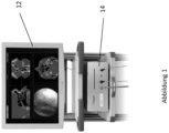
- Figures 1 to 3 show the components of a device according to the invention for displaying image data.
- the device comprises an image processing device 10, to which a display unit 12 is connected on the output side.
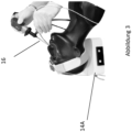
- a position detection device 14 On the input side, a position detection device 14 (see Figures 2 and 3) and an optical device 16 (see Figure 3 ), namely an endoscope.
- the position detection device can, in a known manner, have a field generator 14A for an alternating electromagnetic field and sensor coils that are attached to the device whose position is to be detected.
- the sensor coils are attached invisibly to the endoscope 16, preferably near its distal end.
- the sensor coils are preferably small and have a soft magnetic core.
- Two or three sensor coils are arranged off-center with respect to the longitudinal axis of the endoscope 16 at its distal end and have a different orientation. In this way, in a known manner, not only the position of the individual coils in the alternating electromagnetic field generated by the field generator 14A can be detected, but also their orientation, i.e. alignment. In this way, both the position and the alignment of, for example, a distal end of the endoscope 16 can be precisely determined at a particular point in time.
- the sensor coils are part of the position detection device and are also referred to elsewhere in this text as localizers or - together with their carrier - as the position detection device.
- a further sensor coil 14B is fixedly attached to the relevant body part of the patient (in this case the head).
- the patient's body part - for example the head - is first registered, as is also generally known.
- Position information obtained with the position detection device 14 can then be assigned to a location in the virtual image data, for example in corresponding tomographies of the patient's head.
- the latter allows a known navigation of an instrument by displaying the instrument position in tomographically obtained cross-sectional images of a body part.
- the image processing device 10 allows real image data recorded by the optical instrument 16 and the position information associated with it to be recorded simultaneously. This means that for an individual image recorded by the endoscope 16, the position information is also recorded which describes the position and orientation of the optical device 16 for the moment at which the respective individual image was recorded.
- the image processing device is able, for example, to link real image data recorded by the optical device 16 with virtual image data.
- virtual image data can be image data recorded tomographically.
- the virtual image data can also be data from a three-dimensional model of the respective body part.
- the image processing device 10 to draw structures in a real image recorded by the optical device 10, for example of an elongated hollow organ, which would otherwise not be recognizable in the optically recorded image. If, for example, a hollow organ in a hidden place is shown in the optically recorded image, the contours of this hollow organ can be drawn in the optically recorded image in the correct perspective, for example using light or dark lines. This would, for example, allow a surgeon to easily find a branching vessel, even though it cannot be recognized at all or only with difficulty based on real image data recorded by the optical device.
- virtual image data representing a 3D model of a body part can be obtained precisely by processing real image data recorded by the optical device 16, taking into account the respective associated position information.
- the optical device 16 can be moved through a hollow organ, for example, and thereby successively record a series of individual images of the hollow organ. Since the individual images were recorded from a different position and orientation of the optical device 16, which is known due to the associated position information, they show structures of the hollow organ from different perspectives with the help of characteristic points of the hollow organ that can be recognized in successive individual images. In this way, taking into account the respective position information, a three-dimensional model of the hollow organ can be constructed photogrammetrically based solely on the real image data and the associated position information.
- the image processing device can also be designed so that a three-dimensional model obtained intraoperatively in this way can be used by the image processing device 10 to correct a previously created three-dimensional model of the body part or hollow organ represented by virtual image data in real time and to adapt it to the actual conditions.
- An advantageous embodiment of the image processing device therefore remains an intraoperative model adaptation in real time.
- Another possible processing of virtual and real image data, i.e. image data recorded by the optical device 16, by the image processing device 10 depending on the design variant consists in projecting the real image data onto walls in these virtual image data, so that a three-dimensional model, for example of a body part or hollow organ, can be displayed on the display unit, the surfaces of which appear exactly the same as the real image data recorded by the optical device 16.
- a completely realistic-looking three-dimensional model of the respective body part or hollow organ can thus be displayed on the display unit 12.
- the display unit 12 can be a 3D monitor in a particularly advantageous manner for this purpose.
Landscapes
- Health & Medical Sciences (AREA)
- Surgery (AREA)
- Life Sciences & Earth Sciences (AREA)
- Engineering & Computer Science (AREA)
- Heart & Thoracic Surgery (AREA)
- Animal Behavior & Ethology (AREA)
- Oral & Maxillofacial Surgery (AREA)
- Biomedical Technology (AREA)
- Nuclear Medicine, Radiotherapy & Molecular Imaging (AREA)
- Medical Informatics (AREA)
- Molecular Biology (AREA)
- Pathology (AREA)
- General Health & Medical Sciences (AREA)
- Public Health (AREA)
- Veterinary Medicine (AREA)
- Multimedia (AREA)
- Signal Processing (AREA)
- Endoscopes (AREA)
Description
- Die Erfindung betrifft ein Verfahren sowie eine Vorrichtung zum Darstellen von Bilddaten, bei dem ein optisches Gerät die Lage erfasst und so Lageinformationen gewonnen werden und mit Hilfe der Lageinformationen Bilddaten bestimmt und angezeigt oder weiterverarbeitet werden.
- Unter Lageinformation wird hier die Position und die Ausrichtung des optischen Gerätes in Bezug auf ein Referenzkoordinatensystem, also einem Koordinatensystem einer Lageerfassungseinrichtung verstanden. Die Lageinformation kann mittels einer Lageerfassungseinrichtung mit einem entsprechenden Messsystem erfasst werden.
- Bei vielen chirurgischen Eingriffen existiert für den Chirurgen das Problem der Orientierung im Patienten während der Operation. Als Planungsgrundlage werden oft Bilddaten des Patienten verwendet, z. B. Computertomographieaufnahmen. Während der Operation arbeitet der Arzt mit direktem Blick auf das Operationsgebiet. Dazu stehen ihm optische Visualisierungssysteme/optische Geräte wie Endoskop oder Mikroskop zur Verfügung. Der Arzt muss zur Umsetzung seiner Planung die Verknüpfung zwischen den präoperativen Bilddaten und der intraoperativen visuellen Information herstellten. Dies kann aufgrund von Orientierungsproblemen zur Verlängerung der Operationsdauer oder zu Fehlern bei der Operation führen.
- Als Orientierungshilfe während der Operation sind medizinische Navigationssysteme bekannt. Diese Systeme erfassen während der Operation die Koordinatentransformation zwischen dem Patienten und einem oder mehreren Instrumenten und visualisieren diese in den präoperativen Planungsdaten. Dazu werden Patient und Instrument mit Lokalisatoren ausgestattet, deren Position und Ausrichtung von einem Messsystem als Lageerfassungseinrichtung erfasst werden. Als Messsysteme für eine Lageerfassungseinrichtung werden u. a. elektromagnetische, optische oder Ultraschallsysteme mit entsprechenden Sensoren eingesetzt, wie dies auch für die erfindungsgemäße Vorrichtung in bestimmten Ausführungsformen vorgesehen ist. Die erfindungsgemäße Vorrichtung kann entsprechend ausgestaltet sein. Sie kann entsprechende Einrichtungen hierfür aufweisen.
- Es ist bekannt, unterschiedliche Instrumente mit Lokalisatoren für eines solcher Messsysteme zu versehen, z.B. Zeigeinstrument, Sauger, Zange, Nadeln u. ä. und dieses Instrument einzumessen, so dass eine Koordinatentransformation zu einem Bezugspunkt (i. d. R. die Instrumentenspitze) bekannt ist. Die Position des Bezugspunktes bezüglich der Anatomie des Patienten wird in radiologischen Bilddaten des Patienten auf einem Monitor während der Operation angezeigt.
- Es ist ferner bekannt neben den Instrumenten, die direkt auf eine Struktur gehalten werden, auch ein optisches Hilfsmittel, wie Endoskop, mit Lokalisatoren und einer Vorrichtung zur Distanzmessung zu versehen und einzumessen. Dadurch wird durch das Navigationssystem die Lage des Endoskops erfasst und durch die Vorrichtung zur Distanzmessung wird die Distanz zu einer Struktur von einem Bezugspunkt des Endoskops erfasst. Die Kombination der beiden Informationen erlaubt die Berechnung und Darstellung der Position des berührungslos erfassten Messpunktes in den Bilddaten.
- Es ist bekannt, dass Spulen mit Weicheisenkern als Lokalisatoren in elektromagnetischen Messsystemen mit alternierenden Feldern verwendet werden können. In diesen Spulen werden im wechselnden Feld des sogenannten Feldgenerators des Messsystems charakteristische Spannungen induziert, aus denen die Position der Spule bezüglich des Feldgenerators ermittelt werden kann. Da derartige Spulen als Sensoren in einem elektromagnetischen Messsystem zur Lageerfassung genutzt werden, werden sie auch als Sensorspulen bezeichnet.
- Bei der Darstellung der Position der navigierten Instrumente werden oft Schnittbilder aus einem Volumendatensatz (z. B. computertomografisch gewonnen) verwendet und die Position als Punkt, Kreuz o. Ä. in die Schicht eingezeichnet. Oft werden drei orthogonale Schichten angezeigt.
- Die bekannten Lokalisatoren vieler Messsysteme müssen aufgrund der Baugröße oder aufgrund des Messprinzips an einem Teil eines Instrumentes, dessen Lage erfasst werden soll, angebracht werden, der außerhalb des Patienten bleibt. Dadurch muss das Instrument starr ausgeführt sein, um eine eindeutige Transformation für die Navigation zu gewährleisten. Flexible Instrumente können also mit einer Positionsmesstechnik, die nicht an der Spitze des Instrumentes angebracht werden können, nicht navigiert werden. Gründe für die Anbringung außerhalb des Patienten können das verwendete Messverfahren, Baugröße der verwendeten Sensorik, unzureichende Ergonomie durch Anbringung der Sensorik oder mangelnde Hygiene sein.
- Verfahren zur Darstellung von Bilddaten, bei dem ein optisches Gerät lageerfasst und so Lageinformation gewonnen wird und mit Hilfe der Lageinformation Bilddaten bestimmt und angezeigt oder weiterverarbeitet werden, sind beispielsweise aus den Druckschriften
WO 2007/115825 A1 ,WO 2008/076079 A1 undWO 2008/095068 A1 bekannt. - Dabei ist in der Druckschrift
WO 2007/115825 A1 ein Verfahren beschrieben, bei dem reale Bilddaten mittels eines optischen Gerätes aufgenommen werden, gleichzeitig die Position und/oder Ausrichtung des optischen Gerätes erfasst und hieraus eine Lageinformation abgeleitet wird und die von dem optischen Gerät aufgenommenen, realen Bilddaten unter Einbeziehung der Lageinformation zu virtuellen Bilddaten und/oder zusammen mit den virtuellen Bilddaten zu anzuzeigenden Bilddaten verarbeitet werden. - Aufgabe der Erfindung ist es, eine einfache Vorrichtung zur Navigation einer optischen Visualisierungsvorrichtung oder eines optischen Gerätes und ein Verfahren zur Registrierung und/oder Anzeige von Patientenbilddaten zu dieser optischen Visualisierungsvorrichtung anzugeben.
- Erfindungsgemäß wird diese Aufgabe zum einen durch ein Verfahren zum Darstellen von Bilddaten gemäß Anspruch 1 gelöst, zum anderen durch eine Vorrichtung zum Darstellen von Bilddaten gemäß Anspruch 8, und schließlich auch durch eine medizinische Behandlungsvorrichtung gemäß Anspruch 10, ein digitales Speichermedium gemäß Anspruch 11, ein Computerprogrammprodukt gemäß Anspruch 12 und ein Computerprogramm gemäß Anspruch 13 gelöst.
- Somit werden entweder aus den realen Bilddaten virtuelle Bilddaten generiert, beispielsweise aus realen Bilddaten ein dreidimensionales Modell eines Objekts oder Körperteils erstellt, oder es werden reale, also vom optischen Gerät erfasste Bilddaten mit zuvor generierten virtuellen Bilddaten des jeweiligen Objekts oder Körperteils verknüpft, indem beispielsweise reale Bilddaten in aus den virtuellen Bilddaten abgeleitete Darstellungen eingeblendet werden oder umgekehrt durch virtuelle Bilddaten repräsentierte Strukturen in abgebildete reale Bilddaten eingeblendet werden. Genauso kann auch beides der Fall sein, nämlich dass aus den realen Bilddaten virtuelle Bilddaten generiert und reale Bilddaten in Kombination mit virtuellen Bilddaten zu abzubildenden Bilddaten verarbeitet werden.
- Unter virtuellen Bilddaten werden hier solche Bilddaten verstanden, die nicht unmittelbar von dem optischen Gerät aufgenommen werden, sondern beispielsweise bereits vorher mittels eines tomografischen Verfahrens generiert wurden oder in Form eines dreidimensionalen Modells eines jeweiligen Objekts oder Körperteils vorliegen. Vorzugsweise liegen die virtuellen Bilddaten in Form eines Volumendatensatzes vor, in dem die Bilddaten Koordinaten eines Volumens, d.h. eines virtuellen Raum zugeordnet abgespeichert sind.
- Vorzugsweise werden darzustellende Bilddaten aus den virtuellen Bilddaten unter Berücksichtigung der Blickrichtung des optischen Gerätes bestimmt, d.h. es werden beispielsweise solche durch die virtuellen Bilddaten repräsentierte Strukturen als darzustellende Bilddaten angezeigt, die in Blickrichtung des optischen Gerätes liegen.
- Das Verarbeiten der Bilddaten kann eine Auswahl von anzuzeigenden Bilddaten und/oder eine Transformation der Bilddaten einschließen. Eine Auswahl von Bilddaten ist erforderlich, wenn die virtuellen Bilddaten beispielsweise ein komplettes Körperteil repräsentieren, aber nur die in Blickrichtung des optischen Gerätes liegenden Bilddaten angezeigt werden sollen. Eine Transformation von Bilddaten ist im Weiteren erforderlich, wenn eine Kombination eines realen Objekts oder Körperteils, in dem sich das optische Gerät befindet, mit einem Koordinatensystem in Einklang gebracht werden soll, das dem virtuellen Bilddatensatz zugrunde liegt. Eine Transformation ist auch dann erforderlich, wenn durch einen virtuellen Bilddatensatz repräsentierte Strukturen perspektivrichtig so dargestellt werden sollen, wie es den Abbildungseigenschaften des optischen Gerätes mit seiner jeweiligen aktuellen Position und Ausrichtung entspricht.
- Erfindungsgemäß ist das optische Gerät ein Endoskop. Optische Geräte sind dabei solche Geräte, die optische Bilder aufnehmen, wobei diese Bilder nicht notwendigerweise im sichtbaren Wellenlängenbereich aufgenommen zu werden brauchen. Beispielsweise bietet es sich zum Erfassen realer Bilddaten in Blutgefäßen an, reale Bilddaten mit Hilfe von Infrarotlicht in einem Wellenlängenbereich zu gewinnen, in dem Blut eine hohe Transparenz besitzt.
- Gemäß einer bevorzugten Ausführungsvariante des Verfahrens schließt das Verfahren der aufgenommenen realen Bilddaten eine photogrammetrische Auswertung der realen Bilddaten zur Gewinnung eines dreidimensionalen Modells des Objekts oder Körperteils ein. Auf diese Weise können aus realen Bilddaten Volumendatensätze gewonnen werden. Bevorzugte Ausführungsdetails dieses Verfahrens sind an anderer Stelle in diesem Text näher erläutert.
- Zusätzlich oder alternativ kann das Verfahren so ausgestaltet sein, dass das Verarbeiten der Bilddaten ein Einblenden von virtuellen Bilddaten oder von durch virtuelle Bilddaten repräsentierte Strukturen, Merkmale, Markierungen oder dergleichen in die jeweiligen durch reale Bilddaten repräsentierten Bilder einschließt. Dabei ist es besonders bevorzugt, wenn in reale Bilddaten Konturen von Objekt- oder Körperstrukturen eingeblendet werden, die durch virtuelle Bilddaten repräsentiert sind. Als Beispiel ist hier an anderer Stelle des Textes das Darstellen von einem Hohlgefäß abzweigenden Gefäßen beschrieben.
- Auch kann das Verfahren ganz allgemein die Auswahl und Verarbeitung virtueller Bilddaten zu anzuzeigenden Bilddaten derart einschließen, dass die anzuzeigenden Bilddaten Strukturgrenzen eines Objekts oder Körperteils wiedergeben. Solche Strukturgrenzen werden in virtuellen Bilddaten unter Berücksichtigung der Lageinformation für das optische Geräte vorzugsweise dadurch aufgefunden, dass in Blickrichtung des optischen Gerätes verlaufende Vektoren durch einen von den virtuellen Bilddaten beispielsweise in Form eines Volumendatensatzes repräsentierten Raum gelegt und ein Dichtegradient entlang eines jeweiligen Vektors analysiert wird. Ein hoher Dichtegradient, also ein schneller Hell-Dunkel- oder Dunkel-Hell-Übergang werden dabei jeweils als Strukturgrenze des jeweils repräsentierten Objekts oder Körperteils interpretiert. Allgemein bedeutet ein hoher Dichtegradient eine relative starke Veränderung einer durch die virtuellen Bilddaten repräsentierten Größe (wie z.B. Bildhelligkeit) in einem engen Raumabschnitt oder auf einem kurzen Streckenabschnitt eines beispielsweise durch einen Volumendatensatz repräsentierten virtuellen Raums.
- Eine erfindungsgemäße Vorrichtung zum Darstellen von Bilddaten umfasst ein optisches Gerät, eine Lageerfassungseinrichtung zum Erfassen der Lage des optischen Gerätes, eine mit dem optischen Gerät und der Lageerfassungseinrichtung verbundene Bilddatenverarbeitungseinrichtung und eine mit der Bilddatenverarbeitungseinrichtung verbundene Anzeigeeinheit. Die Bilddatenverarbeitungseinrichtung ist dabei vorzugsweise so konfiguriert, dass sie ein Verfahren gemäß einem oder mehreren der Ansprüche 1 bis 7 ausführt.
- Vorzugsweise weist die Bilddatenverarbeitungseinrichtung einen Speicher für virtuelle Bilddaten auf, dadurch ist die Bilddatenverarbeitungseinrichtung in der Lage, unmittelbar auf virtuelle Bilddaten zurückzugreifen, die im Rahmen des erfindungsgemäßen Verfahrens benötigt werden.
- Erfindungsgemäß ist auch eine medizintechnische Behandlungsvorrichtung vorgesehen, die mit einer Vorrichtung gemäß einem der Ansprüche 8 bis 9 verbunden ist und entsprechend vorzugsweise im Rahmen eines Verfahrens gemäß der Ansprüche 1 bis 7 zu benutzen ist.
- Ebenso ist erfindungsgemäß ein digitales Speichermedium vorgesehen, beispielsweise in Form einer Diskette, einer CD, einer DVD oder eines anderen an sich bekannten Speichermediums, wobei das Speichermedium elektrisch auslesbare Steuersignale enthält, die so konfiguriert sind, dass das digitale Speichermedium derart mit einem programmierbaren Computersystem zusammenwirkt, dass durch maschinelle Schritte ein erfindungsgemäßes Verfahren gemäß einem der Ansprüche 1 bis 7 veranlasst wird.
- Im gleichen Sinne ist erfindungsgemäß auch ein Computerprogrammprodukt vorgesehen, das einen auf einen maschinenlesbaren Träger gespeicherten Programmcode zur Veranlassung der maschinellen Schritte des erfindungsgemäßen Verfahrens gemäß einem der Ansprüche 1 bis 7 aufweist, wenn das Computerprogrammprodukt auf einem Rechner abläuft. Schließlich ist auch ein Computerprogramm in diesem Sinne erfindungsgemäß vorgesehen.
- Weitere vorteilhafte Ausgestaltungen des Verfahrens der Vorrichtung sind die Folgenden:
Ein erfindungsgemäßes digitales Speichermedium, insbesondere in Form einer Diskette, CD oder DVD mit elektrisch auslesbaren Steuersignalen, kann derart mit einem programmierbaren Computersystem zusammenwirken, dass die maschinellen Schritte eines erfindungsgemäßen Verfahrens veranlasst werden. - Dabei können alle, einige oder manche der maschinell durchgeführten Schritte des erfindungsgemäßen Verfahrens veranlasst werden.
- Ein erfindungsgemäßes Computer-Programm-Produkt weist einen auf einem maschinenlesbaren Träger gespeicherten Programmcode zur Veranlassung der maschinellen Schritte des erfindungsgemäßen Verfahrens, wenn das Computer-Programm- Produkt auf einem Rechner abläuft, auf.
- Erfindungsgemäße Weiterbildungen sind jeweils Gegenstand der Unteransprüche und Ausführungsformen.
- Ein auch selbstständig und unabhängig von der Darstellung von Bilddaten schutzfähiger Aspekt betrifft eine Vorrichtung für die Navigation - oder genauer: Lageerfassung - des optischen Geräts, die beispielsweise aus einem Lokalisatorträger, insb. einem Spulenträger besteht oder wenigstens einen solchen aufweist.
- Der Lokalisatorträger hat vorzugsweise einen an das Gerät angepassten Querschnitt, ist in bestimmten Ausführungsformen hohl und hat vorzugsweise eine geringe Wandstärke.
- Der Lokalisatorträger hat in einigen erfindungsgemäßen Ausführungsformen einen passenden Innendurchmesser, so dass er über das Gerät gestülpt und wieder abgezogen werden kann. Vorteilhaft geschieht dies, ohne ein Werkzeug zu verwenden.
- Um den Lokalisatorträger als Spulenträger werden in bestimmten Ausführungsformen Hohlspulen gewickelt. Die Abmessungen der Spulen und der Drahtdurchmesser bestimmen die Induktivität der Spule.
- Die Induktivität bestimmt die Sensitivität im Messsystem. Die Spulen werden über Drähte eines Kabels, die entlang dem Spulenträger verlegt sind kontaktiert. Drahtlose Ausführungen sind ebenfalls von der vorliegenden Erfindung umfasst.
- Über die Spulen - oder erfindungsgemäß anders ausgestaltete Lokalisatoren - und die Drähte (soweit vorhanden) ist zur Kapselung von der Umgebung ein Überzug aufgebracht oder gezogen.
- "Spulen" sind hierin als nicht beschränkende Beispiele für Lokalisatoren oder Sensorspulen zu verstehen. Ein Spulenträger ist daher als ein nicht beschränkendes, spezielles Beispiel eines erfindungsgemäßen Lokalisatorträgers zu verstehen.
- Der Überzug hat einen geeigneten, vorzugsweise hohlen runden, Querschnitt. Erweist in manchen Ausführungsformen eine geringe Wandstärke auf. Spulen und Überzug sind mit dem Spulenträger dauerhaft verbunden, derart, dass die Spulen und der Zwischenraum von außen gekapselt sind. Dies ist vorteilhaft für die hygienische Aufbereitung der Vorrichtung.
- Die optischen Visualisierungssysteme/optischen Geräte werden nachfolgend auch mit dem speziellen Begriff Endoskop beschrieben. Optische Geräte sind erfindungsgemäß Endoskope im engeren Sinne.
- Vorteilhafte Weiterentwicklungen des Verfahrens schließen Navigationsaufsätze für alle Arten von Systemen und insbesondere optischen Geräten ein, mit denen der Arzt während der Operation auf oder in das Operationsgebiet schaut (z. B. Laryngoskop, Gastroskop aber auch Mikroskop, etc.).
- Der Lokalisatorträger stellt einen einfach nutzbaren Aufsatz für u. a. Endoskope dar. Dieser muss in bestimmten Ausführungsformen nur aufgeschoben werden, um ein z. B. das Endoskop zu einem navigierten (d.h. mit Lageerfassungsvorrichtung bzw. Lokalisator ausgestattetem) Instrument zu erweitern.
- In manchen Ausführungsformen befinden sich die Lokalisatoren konzentrisch um das Instrument angeordnet, so dass die Instrumentenachse ohne Einmessung und ohne Dekalibrierungseffekte erfasst wird.
- Ein Lokalisator (z.B. die Spule auf dem Spulenträger) kann sich direkt an der Instrumentenspitze befinden. Die Vorrichtung erlaubt eine kompaktere Gestaltung der Lokalisatoren an der Spitze im Vergleich zu allen anderen bekannten Lokalisatoren. Das Instrument mit Navigationsaufsatz ist in manchen Ausführungsformen nur minimal dicker.
- In weiteren vorteilhaften Ausführungen dient ein Rohr oder eine Hülse (im Querschnitt geschlossen oder teilweise offen) als Spulenträger (oder ganz allgemein als Lokalisatorenträger). Das Rohr kann z. B. aus Metall oder Kunststoff sein.
- Der Überzug kann z. B. ein Rohr sein. Das Rohr kann z. B. aus Metall oder Kunststoff sein.
- Der Überzug und /oder der Spulenträger kann z. B. eine Beschichtung sein, die z. B. mit den, dem Fachmann bekannten, Verfahren CVD, PVD, Wirbelsinter etc. erzeugt werden.
- Der Überzug und/oder der Spulenträger kann z. B. ein temperaturformbares Material sein (z. B. Schrumpfschlauch).
- Der Spulenträger und/oder Überzieher können beide oder einzeln aus einem flexiblen Material sein (z. B. Schlauch).
- Erfindungsgemäß können auf dem Spulenträger eine oder mehrere Spulen aufgebracht werden. In bestimmten Ausführungsformen stimmen die Flächennormale der Spulenöffnung nicht mit ihrer Achse des Instruments oder der Achse des Spulenträgers überein. Dadurch ist es vorteilhaft möglich mit der Spule messtechnisch einen Vektor zu erfassen, der nicht kollinear zur Spulenachse und oder zur Spulenträgerachse ist.
- Als Spulenträger oder Lokalisatorenträger kann bereits auch die Oberfläche des optischen Geräts verwendet werden.
- Der Aufsatz kann in einer vorteilhaften Ausführung am optischen Gerät arretiert werden. Der Aufsatz kann beispielsweise Standardverbindungselemente haben, deren Gegenstück am Instrument ist (z. B. Luer-Lock-Verbindung).
- Der Aufsatz kann ein einer vorteilhaften Ausführungsform für andere Instrumente neben optischen Geräten verwendet werden. Z. B. vorteilhaft ist die Verwendung für Sauger oder Katheter mit Führungskanal.
- Mit Hilfe der Vorrichtung, d.h. dem Lokalisatorträger oder Aufsatz, wird ein jeweiliges optisches Visualisierungssystem/optisches Gerät auf einfache, vorteilhafte Weise zu einem navigierten optischen Instrument. Dadurch können, wie in der Navigation üblich, Visualisierungen von Instrumenten Positionen in virtuellen Bilddaten möglich werden. Bekannt ist die Darstellung eines navigierten Instrumentes in Schnitten des Patienten(Datensatzes) in einem Patientenkoordinatensystem oder einem Koordinatensystem, das durch das navigierte Instrument gebildet wird.
- Das Verfahren der Erfindung erlaubt in manchen erfindungsgemäßen Ausführungsformen vorteilhaft, Visualisierungen an das Operationsverfahren anzupassen und mit Hilfe der Bildinformation des optischen Systems neue Visualisierungsmöglichkeiten zu schaffen.
- In den virtuellen Bilddaten, d.h. in dem durch virtuellen Bilddaten repräsentierten virtuellen Raum, wird die Navigationsinformation durch folgendes Verfahren visualisiert. Die Navigationsinformation wird dem Nutzer durch ein Rechenverfahren zur Verfügung gestellt, dass die Achse des vordersten Segmentes des Instrumentes in "Blickrichtung" virtuell verlängert. Entlang dieses so entstehenden Vektors (auch als Blickvektor bezeichnet) wird ein erster Schnittpunkt mit den virtuellen Bilddaten des Patienten berechnet und somit im virtuellen Bilddatensatz der Punkt gefunden und visualisiert, auf den der Operateur schaut.
- Der Schnittpunkt wird aus dem Gradienten der Bildpunkte des virtuellen Datensatzes entlang des entstehenden Vektors gefunden. Beim Übergang von Luft zu Gewebe tritt ein starker Gradient auf (Helligkeitsunterschied). Ebenso kann der Übergang von Weichgewebe zu Knochen z. B. durch einen Gradientenschwellenwert zugeordnet werden.
- In einer vorteilhaften Ausführung der Erfindung werden mehrere Vektoren zur Detektion mehrerer Punkte oder Linien oder Flächen oder Objekte, die nicht im Zentrum des Endoskops liegen verwendet. Es kann z. B. ein Strahlenbündel mit zwei bis endlich vielen virtuellen Strahlen (Blickvektoren) verwendet werden, die z. B. einen Kegel, vom Endoskop ausgehend, ähnlich dem Sichtkegel, bilden.
- Die Strahlen (Blickvektoren) können auch alle in einer Ebene liegen.
- Die Schnittpunkte der virtuellen Strahlen des Endoskops mit den virtuellen Bilddaten im virtuellen Raum werden mittels z. B. Gradientenbetrachtung berechnet. Die Visualisierung kann vorteilhaft in verschiedenen crosssektionalen Schnittbildern erfolgen, so dass dem Operateur die Übersicht über alle Grenzschichten des Objektes im Strahlenkegel hat.
- Die Schnittbilder (insbesondere die drei orthogonal zueinander stehenden Schnitte) können erfindungsgemäß jeweils zur Strahlennormalen ausgerichtet sein.
- Die Schnittbilder (insbesondere die drei orthogonal zueinander stehenden Schnitte) können alle zur Achse des Instruments ausgerichtet sein.
- Die Schnittbilder (insbesondere die drei orthogonal zueinander stehenden Schnitte) können alle zur Koordinatendefinition des Models ausgerichtet sein.
- Es kann ein Schichtbild in der Ebene des Strahls angezeigt werden und die Strahlen als Linien eingezeichnet werden.
- Die Visualisierung der gefundenen Linien kann in bekannten Schnittbildern erfolgen, (2,5 D Darstellung).
- Die Darstellung kann als 3D-Modell der erfassten Strukturen erfolgen.
- In einer weiteren Ausführung können Objekte sondiert werden. Dabei wird die Tiefeninformation (d.h. der Abstand des virtuellen Strahlursprungs zum Objekt - z.B. repräsentiert durch eine Grenzschicht, die sich in den virtuellen Bilddaten durch einen hohen Dichtegradienten manifestiert - entlang des Strahls) der einzelnen Strahlen verwendet, um Objekte zu identifizieren. Liegt die Tiefeninformation benachbarter Strahlen dicht beieinander, so treffen die Strahlen auf ein Objekt. Ist der Abstand groß, so liegt der eine Strahl auf einem Objekt und der andere liegt auf einem anderen Objekt. Somit werden Objektgrenzen erkannt. Damit können Objekte im virtuellen Modell identifiziert werden.
- Im Sinne der zuvor beschriebenen Visualisierung virtueller Bilddaten kann die tiefeninfonation auch als Länge des Blickvektors von seinem Ursprung bis zum "Schnittpunkt", d.h. bis zu dem Ort an dem ein Dichtegradient oberhalb des Gradientenschwellenwertes vorliegt, verstanden werden.
- In einer weiteren Ausführung können Objekte in den realen Bilddaten durch das optische Visualisierungssystem detektiert werden. Dazu werden diese Daten digitalisiert (Endoskopkamera).
- Für jedes dieser Objekte kann dann ein Schnittbild generiert und angezeigt werden. Das Schnittbild kann z. B. relativ ausgerichtet sein zum Bilddatensatz, zum Instrument oder zu Hauptträgheitsachse des Objektes selbst. Durch mehrere aufeinander folgende Bilddaten entlang einer Bewegungstrajektorie können Objekt detektiert und differenziert werden. Dazu werden photogrammetrische Verfahren verwendet. Vorstellbar ist, dass Features (z. B. Kanten) in einzelnen Bildern erkannt werden. Durch eine Zuordnung der Features zwischen mehreren Bildern kann aufgrund der verschiedenen Bewegung der Features auf verschiedene Objekte geschlossen werden. Zur Verdeutlichung: ein näher liegendes Objekt verändert seine Größe schneller als ein weiter entferntes Objekt. Diesen identifizierten Objekten kann aufgrund der Navigationsinformationen des navigierten Aufsatzes Lageinformationen zugeordnet werden. Es entsteht ein Objektbasiertes 3D-Modell aus den realen Bilddaten.
- In einer weiteren Ausführung können die erkannten Objekte im realen und virtuellen Modell in Beziehung zu einander verwendet werden. Es wird z. B. das virtuelle Modell aus dem Vergleich der zugeordneten Objekte angepasst. Fehlt aufgrund des Operationsfortschritts ein Objekt im realen Modell wird das entsprechende Objekt im virtuellen Modell entfernt (intraoperative Modellanpassung). Ist ein Objekt in beiden Modellen vorhanden jedoch zueinander verschieden, kann die Lage des virtuellen Modells mit Hilfe dieser Transformationsinformation angepasst werden (Adaptive Patientenregistrierung).
- Ist zu erwarten, dass sich die realen Objekte im Raum zu einander bewegen können (Weichgewebe), kann aus der Lageabweichung der Modelle eine Weichteilbewegung erkannt werden. Das virtuelle Modell kann dementsprechend angepasst werden.
- Das navigierte Instrument, also beispielsweise das optische Gerät mit Lageerfassungseinrichtung, das durch die Verwendung des Aufsatzes entsteht (optisches Visualisierungssystem mit Navigationsaufsatz) wird durch das beschriebene Verfahren für die Registrierung der Patientendaten verwendet. Dabei werden mehrere Objekte in den realen Bilddaten zu virtuellen Objekten zugeordnet. Beispielsweise eignen sich dazu die Nasenöffnungen, Augenhöhlen, Ohrmuscheln. Ein in beiden Modellen bekanntes Objekt muss dabei in den realen Bildern immer sichtbar sein und identifiziert werden. Dazu eignet sich der sogenannte Patientenlokalisator.
- Das Verfahren kann auch dazu verwendet werden, um die Transformation des virtuellen Modells zum realen Modell zu bestimmen. Dadurch können beispielsweise Objekte, die im Videobild gar nicht vorhanden sind, z. B. Planungsdaten (für Rekonstruktion, Implantate etc.), die im virtuellen Datensatz geplant sind, im realen Videobild oder in dem realen Modell dargestellt werden. Ebenso können verdeckte Strukturen im realen Videobild (z. B. Abzweige von Adern, Zielregionen) überlagert dargestellt werden, beispielsweise indem die Konturen der verdeckten Strukturen perspektivrichtig in ein reales Bild (beispielsweise mit hellen oder dunklen Linien) "eingezeichnet" werden.
- In einer weiteren vorteilhaften Ausführung der Erfindung wird über alle sichtbaren Punkte eine virtuelle Oberflächenabtastung vorgenommen und die Informationen dann auf ein geeignetes Referenzobjekt projiziert, nach Verfahren, die z. B. aus der geographischen Kartenherstellung bekannt sind. Daraus ergibt sich eine neue Art der Darstellung. Das Verfahren ist auch mit Linien als Abwandlung einer zylindrischen Projektion anwendbar. Das geeignete Referenzobjekt kann beispielsweise ein einfaches geometrisches Objekt wie z.B. ein Zylinder sein. Das Referenzobjekt kann aber auch ein virtuelles dreidimensionales Modell eines von einem optischen Gerät erfassten Objekts sein. In beiden Fällen werden vom optischen Gerät erfasste Bilddaten undvirtuelle Bilddaten unter Auswertung der Lageinformation miteinander verknüpft.
- Die Visualisierung der detektierten Punkte kann auch im korrespondierenden Videobild eines Videoendoskops erfolgen. Zuvor müssen die Abbildungseigenschaften bei der Aufnahme des Videobildes erfasst worden sein.
- Durch die beschriebenen Projektionsverfahren besteht die Möglichkeit einer völlig neuen Informationsdarstellung (z.B. der Tunnelentzerrung). Hier werden geeignete virtuelle Bildpunkte, durch geeignete Vektoranordnungen aus dem Patientenbilddatensatz extrahiert, z. B. kreisförmig oder linienförmig oder vollständig in Gefäßen. Das Ergebnis wird dann auf vordefinierte Zielstrukturen projiziert, z. B. Zylinder, Kugeln, Ellipsoide. Erfindungsgemäß wird somit in manchen Ausführungsformen eine vorteilhafte, also eine an die Operationsweise angepasste Darstellung der Navigationsinformation des navigierten Instruments möglich.
- Das erfindungsgemäße Verfahren und seine Varianten sowie die erfindungsgemäße Vorrichtung und weitere vorteilhafte Ausgestaltungen des Verfahrens und der Vorrichtung sind der nachfolgenden Beschreibung eines Ausführungsbeispiels zu entnehmen. Die beigefügten Abbildungen zeigen beispielhaft Aspekte einer erfindungsgemäßen Vorrichtung, nämlich in
- Abb. 1:
- eine Bilddatenverarbeitungseinrichtung und eine mit der Bilddatenverarbeitungsvorrichtung verbundene Anzeigeeinheit;
- Abb. 2:
- eine Lageerfassungseinrichtung zum Erfassen der Lage des optischen Gerätes;
- Abb. 3:
- ein optisches Gerät und die Lageerfassungseinrichtung zum Erfassen der Lage des optischen Gerätes.
- Die Abbildungen 1 bis 3 zeigen die Komponenten einer erfindungsgemäßen Vorrichtung zur Darstellung von Bilddaten. Die Vorrichtung umfasst eine Bildverarbeitungseinrichtung 10, an die ausgangsseitig eine Anzeigeeinheit 12 angeschlossen ist. Eingangsseitig sind an die Bildverarbeitungseinrichtung 10 eine Lageerfassungseinrichtung 14 (siehe Abbildungen 2 und 3) sowie ein optisches Gerät 16 (siehe
Abbildung 3 ), nämlich ein Endoskop, angeschlossen. - Die Lageerfassungseinrichtung kann in sich bekannter Weise einen Feldgenerator 14A für ein elektromagnetisches Wechselfeld aufweisen sowie Sensorspulen, die an dem Gerät befestigt sind, dessen Lage erfasst werden soll. In diesem Falle sind die Sensorspulen nicht erkennbar an dem Endoskop 16 angebracht, und zwar vorzugsweise in der Nähe von dessen distalem Ende. Bevorzugt sind die Sensorspulen klein und besitzen einen weichmagnetischen Kern. Zwei oder drei Sensorspulen sind außermittig in Bezug auf die Längsachse des Endoskopes 16 an dessen distalem Ende angeordnet und weisen eine unterschiedliche Orientierung auf. Auf diese Weise kann in an sich bekannter Weise nicht nur die Lage der einzelnen Spulen in dem von dem Feldgenerator 14A erzeugten elektromagnetischen Wechselfeld erfasst werden, sondern auch deren Orientierung, d.h. Ausrichtung. Auf diese Weise kann mit der Lageerfassungseinrichtung 14 sowohl die Position als auch die Ausrichtung beispielsweise eines distalen Endes des Endoskopes 16 zu einem jeweiligen Zeitpunkt genau bestimmt werden.
- Die Sensorspulen sind Teil der Lageerfassungseinrichtung und werden an anderer Stelle in diesem Text auch als Lokalisatoren oder- zusammen mit ihrem Träger - als Lageerfassungsvorrichtung bezeichnet.
- Damit diese Lageinformation in Bezug auf einen Patienten 18 aussagekräftig ist, ist eine weitere Sensorspule 14B ortsfest am relevanten Körperteil des Patienten (in diesem Falle dem Kopf) befestigt.
- Um virtuelle Bilddaten, also beispielsweise tomografisch gewonnene Schnittbilder des Patientenkopfes, mit den von der Lageerfassungseinrichtung 14 erfassten augenblicklichen Positionen in Einklang zu bringen, wird zunächst eine Registrierung des Körperteils des Patienten - beispielsweise also des Kopfes - vorgenommen, wie dies ebenfalls grundsätzlich bekannt ist. Anschließend kann eine jeweils mit der Lageerfassungseinrichtung 14 gewonnene Lageinformation einen Ort in den virtuellen Bilddaten, also beispielsweise in entsprechenden Tomografien des Patientenkopfes, zugeordnet werden.
- Letztes erlaubt eine an sich bekannte Navigation eines Instrumentes durch Darstellung der Instrumentenposition in tomografisch gewonnenen Schnittbildern eines Körperteils.
- Abweichend oder ergänzend zu dieser an sich bekannten Navigation erlaubt es die Bildverarbeitungseinrichtung 10, vom optischen Instrument 16 aufgenommene reale Bilddaten und diesen jeweils zugeordnete Lageinformationen gleichzeitig zu erfassen. Dies bedeutet, dass zu einem von dem Endoskop 16 aufgenommenen Einzelbild auch jeweils die Lageinformation aufgenommen wird, die die Position und Ausrichtung des optischen Gerätes 16 für den Augenblick beschreibt, zu dem das jeweilige Einzelbild aufgenommen wurde.
- Auf diese Weise ist die Bildverarbeitungseinrichtung beispielsweise in der Lage, vom optischen Gerät 16 aufgenommene reale Bilddaten mit virtuellen Bilddaten zu verknüpfen. Solche virtuellen Bilddaten können tomografisch aufgenommene Bilddaten sein. Die virtuellen Bilddaten können aber auch Daten eines dreidimensionalen Modells des jeweiligen Körperteils sein.
- Auf diese Weise ist es beispielsweise möglich, dass die Bildverarbeitungseinrichtung 10 in ein reales, von dem optischen Gerät 10 aufgenommenes Bild, beispielsweise eines länglichen Hohlorgans, Strukturen einzeichnet, die auf dem optisch aufgenommenen Bild sonst nicht zu erkennen wären. Zeigt von dem Hohlorgan, das von dem optisch aufgenommenen Bild dargestellt wird, beispielsweise ein Hohlorgan an versteckter Stelle ab, so können die Konturen dieses Hohlorgans perspektivisch richtig, beispielsweise durch helle oder dunkle Linien, in das optisch aufgenommene Bild eingezeichnet werden. Dies würde es beispielsweise einem Operateur erlauben, ein abzweigendes Gefäß leicht zu finden, obwohl es auf Basis realer, von dem optischen Gerät aufgenommener Bilddaten gar nicht oder nur schwer zu erkennen ist.
- In einem alternativen Szenario können mit der erfindungsgemäßen Vorrichtung zum Darstellen von Bilddaten ein 3D-Modell eines Körperteils repräsentierende virtuelle Bilddaten gerade dadurch gewonnen werden, dass von dem optischen Gerät 16 aufgenommene reale Bilddaten unter Berücksichtigung der jeweils zugehörigen Lageinformation bearbeitet werden. Dazu kann das optische Gerät 16 durch beispielsweise ein Hohlorgan hindurchbewegt werden und dabei sukzessive eine Folge von Einzelbildern des Hohlorgans aufnehmen. Da die Einzelbilder von jeweils unterschiedlicher, aber aufgrund der zugehörigen Lageinformation bekannter Position und Ausrichtung des optischen Gerätes 16 aufgenommen wurden, zeigen sie Strukturen des Hohlorgans aus unterschiedlicher Perspektive mit Hilfe in aufeinanderfolgenden Einzelbildern wiedererkennbaren charakteristischen Punkten des Hohlorgans. So kann unter Berücksichtigung der jeweiligen Lageinformation auf photogrammetrischem Wege ein dreidimensionales Modell des Hohlorgans allein auf Basis der realen Bilddaten und der zugehörigen Lageinformation konstruiert werden.
- In einem weitergehenden Schritt kann die Bildverarbeitungseinrichtung auch dazu ausgebildet sein, dass ein auf diese Weise intraoperativ gewonnenes dreidimensionales Modell von der Bildverarbeitungseinrichtung 10 dazu herangezogen werden kann, ein durch virtuelle Bilddaten repräsentiertes, zuvor erstelltes dreidimensionales Modell des Körperteils oder Hohlorgans in Echtzeit zu korrigieren und an die tatsächlichen Gegebenheiten anzupassen. Eine vorteilhafte Ausführungsvariante der Bildverarbeitungseinrichtung bleibt somit eine intraoperative Modellanpassung in Echtzeit.
- Eine weitere von der Bildverarbeitungseinrichtung 10 je nach Ausführungsvariante mögliche Verarbeitung virtueller und realer, d.h. vom optischen Gerät 16 aufgenommener, Bilddaten besteht darin, dass die realen Bilddaten gewissermaßen auf Wände in diesen virtuellen Bilddaten projiziert werden, so dass auf der Anzeigeeinheit ein dreidimensionales Modell, beispielsweise eines Körperteils oder Hohlorgans, dargestellt werden kann, dessen Oberflächen genauso erscheinen, dass sie den vom optischen Gerät 16 erfassten realen Bilddaten in ihrem Aussehen entsprechen. Somit kann ein vollkommen realistisch aussehendes dreidimensionales Modell des jeweiligen Körperteils oder Hohlorgans auf der Anzeigeeinheit 12 dargestellt werden. Die Anzeigeeinheit 12 kann zu diesem Zweck in besonders vorteilhafter Weise ein 3D-Monitor sein.
Claims (13)
- Verfahren zur Darstellung von Bilddaten, bei dem ein optisches Gerät lageerfasst und so Lageinformation gewonnen wird und mit Hilfe der Lageinformation Bilddaten bestimmt und angezeigt oder weiterverarbeitet werden, wobei die Lageinformation des optischen Geräts mittels eines medizinischen Navigationssystems erfasst wird, das während einer Operation eine Koordinatentransformation zwischen einem Patienten und dem optischen Gerät erfasst und dieses in präoperativen Planungsdaten visualisiert, wobei der Patient und das optische Gerät mit Lokalisatoren ausgestattet sind, deren Position und Ausrichtung von einem Messsystem als Lageerfassungseinrichtung erfasst werden, wobei die anzuzeigenden Bilddaten wenigstens teilweise auf virtuellen, nicht unmittelbar von dem optischen Gerät erfassten Bilddaten beruhen, die ein Objekt oder Körperteil repräsentieren welches sich in einem Blickbereich des optischen Gerätes befindet, wobei im Rahmen des Verfahrens:- reale Bilddaten mittels eines optischen Gerätes aufgenommen werden,- gleichzeitig die Position und Ausrichtung des optischen Gerätes erfasst und hieraus eine Lageinformation abgeleitet wird,- die von dem optischen Gerät aufgenommenen realen Bilddaten unter Einbeziehung der Lageinformation zu virtuellen Bilddaten und/oder zusammen mit den virtuellen Bilddaten zu anzuzeigenden Bilddaten verarbeitet werden,wobei das optische Gerät eine Blickrichtung hat und darzustellende Bilddaten aus den virtuellen Bilddaten unter Berücksichtigung der Blickrichtung des optischen Gerätes bestimmt werden und wobei verdeckte Strukturen in den realen Bilddaten überlagert dargestellt werden und wobei das obtische Gerät ein Endoskop ist.
- Verfahren nach Anspruch 1, dadurch gekennzeichnet, dass die virtuellen Bilddaten mittels eines tomographischen Verfahrens gewonnen sind und/oder Daten eines dreidimensionalen Modells eines Objekts oder Körperteils sind.
- Verfahren nach einem der Ansprüche 1 bis 2, dadurch gekennzeichnet, dass das Verarbeiten der Bilddaten eine Auswahl von anzuzeigenden Bilddaten und/oder eine Transformation der Bilddaten einschließt.
- Verfahren nach einem der Ansprüche 1 bis 3, dadurch gekennzeichnet, dass das Verarbeiten der aufgenommenen Bilddaten eine photogrammetrische Auswertung der realen Bilddaten zur Gewinnung eines dreidimensionalen Modells des Objekts oder Körperteils einschließt.
- Verfahren nach einem der Ansprüche 1 bis 4, dadurch gekennzeichnet, dass das Verarbeiten der Bilddaten ein Einblenden von virtuellen Bilddaten in die jeweiligen realen Bilddaten einschließt.
- Verfahren nach Anspruch 5, dadurch gekennzeichnet, dass in reale Bilddaten Konturen von Objekt- oder Körperteilstrukturen eingeblendet werden, die durch virtuelle Bilddaten repräsentiert sind.
- Verfahren nach einem der Ansprüche 1 bis 6, dadurch gekennzeichnet, dass anzuzeigende Bilddaten unter Berücksichtigung virtueller Bilddaten in Form von Tomographien und unter Berücksichtigung der Blickrichtung des optischen Gerätes dadurch bestimmt werden, dass der Blickrichtung des optischen Gerätes entsprechende Blickvektoren in den virtuellen Bilddaten derart analysiert werden, dass starker Dichtegradient entlang eines jeweiligen Blickvektors als Strukturgrenze des jeweils repräsentierten Objekts oder Körperteils interpretiert wird.
- Vorrichtung zur Darstellung von Bilddaten, welche ein optisches Gerät, eine Lageerfassungseinrichtung zum Erfassen der Lage des optischen Gerätes, eine mit dem optischen Gerät und der Lageerfassungseinrichtung verbundene Bilddatenverarbeitungseinrichtung und eine mit der Bilddatenverarbeitungsvorrichtung verbundene Anzeigeeinheit aufweist, wobei die Bilddatenverarbeitungsvorrichtung dazu konfiguriert ist, ein Verfahren gemäß den Ansprüchen 1 bis 7 auszuführen.
- Vorrichtung nach Anspruch 8, dadurch gekennzeichnet, dass die Bilddatenverarbeitungsvorrichtung eine Speicher für virtuelle Bilddaten aufweist.
- Medizintechnische Behandlungsvorrichtung verbunden mit wenigstens einer Vorrichtung nach Anspruch 8 oder 9 und/oder zum Durchführen wenigstens eines Verfahrens nach einem der Ansprüche 1 bis 7.
- Digitales Speichermedium, insbesondere in Form einer Diskette, CD oder DVD, mit elektrisch auslesbaren Steuersignalen, konfiguriert, um derart mit einem programmierbaren Computersystem zusammenwirken, dass die maschinellen Schritte eines erfindungsgemäßen Verfahrens nach einem der Ansprüche 1 bis 7 veranlasst werden.
- Computer-Programm-Produkt mit einem auf einem maschinenlesbaren Träger gespeicherten Programmcode zur Veranlassung der maschinellen Schritte des erfindungsgemäßen Verfahrens gemäß einem der Ansprüche 1 bis 7, wenn das Computer-Programm- Produkt auf einem Rechner abläuft.
- Computer-Programm mit einem Programmcode zur Veranlassung der maschinellen Schritte eines erfindungsgemäßen Verfahrens gemäß einem der Ansprüche 1 bis 7, wenn das Computer-Programm auf einem Computer abläuft.
Applications Claiming Priority (2)
| Application Number | Priority Date | Filing Date | Title |
|---|---|---|---|
| DE102010049702 | 2010-10-28 | ||
| PCT/EP2011/069065 WO2012056034A1 (de) | 2010-10-28 | 2011-10-28 | Navigationsaufsatz für optische geräte in der medizin und verfahren |
Publications (3)
| Publication Number | Publication Date |
|---|---|
| EP2632382A1 EP2632382A1 (de) | 2013-09-04 |
| EP2632382B1 EP2632382B1 (de) | 2017-09-20 |
| EP2632382B2 true EP2632382B2 (de) | 2024-06-26 |
Family
ID=44906093
Family Applications (1)
| Application Number | Title | Priority Date | Filing Date |
|---|---|---|---|
| EP11778578.2A Active EP2632382B2 (de) | 2010-10-28 | 2011-10-28 | Navigationsaufsatz für optische geräte in der medizin und verfahren |
Country Status (5)
| Country | Link |
|---|---|
| US (1) | US9641808B2 (de) |
| EP (1) | EP2632382B2 (de) |
| CN (1) | CN103237518A (de) |
| DE (1) | DE202011110755U1 (de) |
| WO (1) | WO2012056034A1 (de) |
Families Citing this family (18)
| Publication number | Priority date | Publication date | Assignee | Title |
|---|---|---|---|---|
| DE102011078212B4 (de) | 2011-06-28 | 2017-06-29 | Scopis Gmbh | Verfahren und Vorrichtung zum Darstellen eines Objektes |
| DE102012208389A1 (de) * | 2012-05-18 | 2013-11-21 | Fiagon Gmbh | Registrierverfahren und -vorrichtung für ein Positionserfassungssystem |
| DE102012220115A1 (de) * | 2012-11-05 | 2014-05-22 | Fraunhofer-Gesellschaft zur Förderung der angewandten Forschung e.V. | Bildgebendes System, Operationsvorrichtung mit dem bildgebenden System und Verfahren zur Bildgebung |
| JP6138566B2 (ja) * | 2013-04-24 | 2017-05-31 | 川崎重工業株式会社 | 部品取付作業支援システムおよび部品取付方法 |
| DE102013211055B3 (de) | 2013-06-13 | 2014-09-18 | Scopis Gmbh | Adapter zur Aufnahme eines medizintechnischen Geräts sowie eines Lageerfassungssystems |
| DE102013214067A1 (de) | 2013-07-17 | 2015-01-22 | Fiagon Gmbh | Vorrichtung und Verfahren zur Anbindung eines medizinischen Instruments an ein Lageerfassungssystem |
| DE102013222230A1 (de) | 2013-10-31 | 2015-04-30 | Fiagon Gmbh | Chirurgisches Instrument |
| WO2015087331A1 (en) * | 2013-12-11 | 2015-06-18 | Barak Katz | Method and system for monitoring activity of an individual |
| GB2524955A (en) | 2014-04-01 | 2015-10-14 | Scopis Gmbh | Method for cell envelope segmentation and visualisation |
| GB201501157D0 (en) | 2015-01-23 | 2015-03-11 | Scopis Gmbh | Instrument guidance system for sinus surgery |
| US10163262B2 (en) * | 2015-06-19 | 2018-12-25 | Covidien Lp | Systems and methods for navigating through airways in a virtual bronchoscopy view |
| EP3184071A1 (de) * | 2015-12-22 | 2017-06-28 | SpineMind AG | Vorrichtung für die intraoperative bildgesteuerte navigation bei chirurgischen eingriffen im bereich der wirbelsäule und im daran angrenzenden thorax-, becken- oder kopfbereich |
| BR112018016910A2 (pt) * | 2016-02-19 | 2018-12-26 | Koninklijke Philips Nv | sistema de tratamento, método para determinar a posição de um dispositivo de tratamento de um sistema de tratamento, e produto de programa de computador |
| CA3015179A1 (en) | 2016-03-08 | 2016-12-08 | Antisep - Tech Ltd. | Method and system for monitoring activity of an individual |
| CN111032140B (zh) | 2017-08-16 | 2022-08-16 | 直观外科手术操作公司 | 用于在医疗程序期间监测患者运动的系统和方法 |
| CN111278381B (zh) | 2017-08-28 | 2024-04-09 | 皇家飞利浦有限公司 | 对定位跟踪的介入设备的自动视场更新 |
| EP3719749B1 (de) | 2019-04-03 | 2026-01-14 | Fiagon GmbH | Registrierungsverfahren und -einrichtung |
| EP4552602B1 (de) | 2020-08-07 | 2026-03-18 | Brainlab SE | Echtzeit-augmentation |
Citations (2)
| Publication number | Priority date | Publication date | Assignee | Title |
|---|---|---|---|---|
| WO1996005768A1 (en) † | 1994-08-19 | 1996-02-29 | Biosense, Inc. | Medical diagnosis, treatment and imaging systems |
| WO2006095027A1 (en) † | 2005-03-11 | 2006-09-14 | Bracco Imaging S.P.A. | Methods and apparati for surgical navigation and visualization with microscope |
Family Cites Families (11)
| Publication number | Priority date | Publication date | Assignee | Title |
|---|---|---|---|---|
| US8253779B2 (en) * | 2000-10-11 | 2012-08-28 | University of Pittsbugh—Of The Commonwealth System of Higher Education | System for remote guidance by expert for imaging device |
| JP4698966B2 (ja) * | 2004-03-29 | 2011-06-08 | オリンパス株式会社 | 手技支援システム |
| GB0505782D0 (en) * | 2005-03-22 | 2005-04-27 | Depuy Int Ltd | Surgical guide |
| WO2007115825A1 (en) | 2006-04-12 | 2007-10-18 | Nassir Navab | Registration-free augmentation device and method |
| US8248413B2 (en) * | 2006-09-18 | 2012-08-21 | Stryker Corporation | Visual navigation system for endoscopic surgery |
| CN101681504A (zh) * | 2006-11-27 | 2010-03-24 | 皇家飞利浦电子股份有限公司 | 用于将实时超声图像与预先获取的医学图像进行融合的系统和方法 |
| WO2008076079A1 (en) | 2006-12-19 | 2008-06-26 | Bracco Imaging S.P.A. | Methods and apparatuses for cursor control in image guided surgery |
| US8672836B2 (en) * | 2007-01-31 | 2014-03-18 | The Penn State Research Foundation | Method and apparatus for continuous guidance of endoscopy |
| JP5639764B2 (ja) * | 2007-03-08 | 2014-12-10 | シンク−アールエックス,リミティド | 運動する器官と共に使用するイメージング及びツール |
| CN100586379C (zh) * | 2008-07-04 | 2010-02-03 | 浙江大学 | 一种计算机模拟定标活检方法及装置 |
| DE102009040430B4 (de) * | 2009-09-07 | 2013-03-07 | Fraunhofer-Gesellschaft zur Förderung der angewandten Forschung e.V. | Vorrichtung, Verfahren und Computerprogramm zur Überlagerung eines intraoperativen Livebildes eines Operationsgebiets oder des Operationsgebiets mit einem präoperativen Bild des Operationsgebiets |
-
2011
- 2011-10-28 EP EP11778578.2A patent/EP2632382B2/de active Active
- 2011-10-28 CN CN2011800586968A patent/CN103237518A/zh active Pending
- 2011-10-28 DE DE202011110755.1U patent/DE202011110755U1/de not_active Expired - Lifetime
- 2011-10-28 US US13/881,770 patent/US9641808B2/en active Active
- 2011-10-28 WO PCT/EP2011/069065 patent/WO2012056034A1/de not_active Ceased
Patent Citations (2)
| Publication number | Priority date | Publication date | Assignee | Title |
|---|---|---|---|---|
| WO1996005768A1 (en) † | 1994-08-19 | 1996-02-29 | Biosense, Inc. | Medical diagnosis, treatment and imaging systems |
| WO2006095027A1 (en) † | 2005-03-11 | 2006-09-14 | Bracco Imaging S.P.A. | Methods and apparati for surgical navigation and visualization with microscope |
Non-Patent Citations (3)
| Title |
|---|
| CHEN JING ET AL.: "Navigation System for Endoscopic Sinus Surgery Based on Augmented Reality", IEEE /ICCME INTERNATIONAL CONFERENCE ON COMPLEX MEDICAL ENGINEERING, 2007, Beijing, pages 185 - 188, XP031159910 † |
| Clinical User Guide" Revision 1.2, VectorVision cranial/ENT.Version 7.8, mit Copyright 2008 und nachweisbar veröffentlicht im Jahr 2008 im Rahmen einer offenkundigen Vorbenutzung durch Brainlab (vgl. 01 bis 06 und die folgenden Ausführungenin diesem Abschnitt) † |
| ICME INTERNATIONAL C ONFERENCE ON, IEEE, PI, 1. Mai2007 (2007-05-01), Seiten 185 188 ISBN: 978-1-4244-1077-4 † |
Also Published As
| Publication number | Publication date |
|---|---|
| US20130258079A1 (en) | 2013-10-03 |
| DE202011110755U1 (de) | 2016-02-22 |
| EP2632382A1 (de) | 2013-09-04 |
| US9641808B2 (en) | 2017-05-02 |
| EP2632382B1 (de) | 2017-09-20 |
| CN103237518A (zh) | 2013-08-07 |
| WO2012056034A1 (de) | 2012-05-03 |
Similar Documents
| Publication | Publication Date | Title |
|---|---|---|
| EP2632382B2 (de) | Navigationsaufsatz für optische geräte in der medizin und verfahren | |
| DE69922980T2 (de) | Verfahren und vorrichtung zur positionierung eines geräts in einem körper | |
| DE102004008164B3 (de) | Verfahren und Vorrichtung zum Erstellen zumindest eines Ausschnitts eines virtuellen 3D-Modells eines Körperinnenraums | |
| DE102011083522B4 (de) | Verfahren und Vorrichtung zur Visualisierung der Qualität eines Ablationsvorgangs | |
| EP3076369B1 (de) | Verfahren und vorrichtung zum darstellen eines objektes | |
| DE102006001884A1 (de) | Verfahren zur bildlichen Unterstützung einer Führung eines in einen Hohlraum eines Untersuchungsobjekts mindestens teilweise eingeführten medizinischen Instruments | |
| EP4213755B1 (de) | Chirurgisches assistenzsystem | |
| EP3500152B1 (de) | Detektionssystem zur automatischen detektion chirurgischer instrumente | |
| EP3412242A1 (de) | Ausgabe von positionsinformationen eines medizintechnischen instruments | |
| DE4417944A1 (de) | Verfahren zum Korrelieren verschiedener Koordinatensysteme in der rechnergestützten, stereotaktischen Chirurgie | |
| WO2005027765A1 (de) | Verfahren und vorrichtung zur visuellen unterstützung einer elektrophysiologischen katheteranwendung im herzen | |
| EP3598948B1 (de) | Bildgebendes system und verfahren zum erzeugen einer stereoskopischen darstellung, computerprogramm und datenspeicher | |
| DE10160530B4 (de) | Verfahren und Anlage zur Magnetresonanz-Bildgebung | |
| EP4228543B1 (de) | Chirurgisches navigationssystem mit verbessertem instrumententracking und navigationsverfahren | |
| DE10157965A1 (de) | Navigationssystem mit Atem- bzw. EKG-Triggerung zur Erhöhung der Navigationsgenauigkeiten | |
| DE102021117004A1 (de) | Chirurgisches Assistenzsystem mit verbesserter Registrierung und Registrierverfahren | |
| DE102012224057B4 (de) | Verfahren und Vorrichtung zur Bildunterstützung | |
| DE102019200786A1 (de) | Bildgebendes medizinisches Gerät, Verfahren zum Unterstützen von medizinischem Personal, Computerprogrammprodukt und computerlesbares Speichermedium | |
| EP1464285B1 (de) | Perspektivische Registrierung und Visualisierung interner Körperbereiche | |
| DE102010018291B4 (de) | Navigationssystem und Röntgensystem | |
| EP2441410A1 (de) | Verfahren zum Erstellen eines medizinischen Bildes und medizinischer Arbeitsplatz | |
| DE102011114146A1 (de) | Verfahren und Vorrichtung zum Darstellen eins Objektes | |
| DE102008033641A1 (de) | Medizinische Untersuchungs- und Behandlungseinrichtung zur Visualisierung und Behandlung von Ablationsläsionen | |
| DE102010039598B4 (de) | Verfahren zur Bildüberwachung eines medizinischen Eingriffs mit einer Nadel und Röntgeneinrichtung | |
| DE102021204728A1 (de) | Verfahren und System zum Bereitstellen eines korrigierten Datensatzes |
Legal Events
| Date | Code | Title | Description |
|---|---|---|---|
| REG | Reference to a national code |
Ref country code: DE Ref legal event code: R138 Ref document number: 202011110755 Country of ref document: DE Free format text: GERMAN DOCUMENT NUMBER IS 502011013032 |
|
| PUAI | Public reference made under article 153(3) epc to a published international application that has entered the european phase |
Free format text: ORIGINAL CODE: 0009012 |
|
| 17P | Request for examination filed |
Effective date: 20130528 |
|
| AK | Designated contracting states |
Kind code of ref document: A1 Designated state(s): AL AT BE BG CH CY CZ DE DK EE ES FI FR GB GR HR HU IE IS IT LI LT LU LV MC MK MT NL NO PL PT RO RS SE SI SK SM TR |
|
| DAX | Request for extension of the european patent (deleted) | ||
| 17Q | First examination report despatched |
Effective date: 20150427 |
|
| REG | Reference to a national code |
Ref country code: DE Ref legal event code: R079 Ref document number: 502011013032 Country of ref document: DE Free format text: PREVIOUS MAIN CLASS: A61B0019000000 Ipc: A61B0090000000 |
|
| RIC1 | Information provided on ipc code assigned before grant |
Ipc: A61B 90/00 20160101AFI20161025BHEP |
|
| GRAP | Despatch of communication of intention to grant a patent |
Free format text: ORIGINAL CODE: EPIDOSNIGR1 |
|
| STAA | Information on the status of an ep patent application or granted ep patent |
Free format text: STATUS: GRANT OF PATENT IS INTENDED |
|
| INTG | Intention to grant announced |
Effective date: 20161207 |
|
| GRAJ | Information related to disapproval of communication of intention to grant by the applicant or resumption of examination proceedings by the epo deleted |
Free format text: ORIGINAL CODE: EPIDOSDIGR1 |
|
| STAA | Information on the status of an ep patent application or granted ep patent |
Free format text: STATUS: EXAMINATION IS IN PROGRESS |
|
| GRAP | Despatch of communication of intention to grant a patent |
Free format text: ORIGINAL CODE: EPIDOSNIGR1 |
|
| STAA | Information on the status of an ep patent application or granted ep patent |
Free format text: STATUS: GRANT OF PATENT IS INTENDED |
|
| INTC | Intention to grant announced (deleted) | ||
| INTG | Intention to grant announced |
Effective date: 20170301 |
|
| GRAS | Grant fee paid |
Free format text: ORIGINAL CODE: EPIDOSNIGR3 |
|
| RIN1 | Information on inventor provided before grant (corrected) |
Inventor name: KRUEGER, TIMO Inventor name: ROSE, ANDREAS |
|
| GRAA | (expected) grant |
Free format text: ORIGINAL CODE: 0009210 |
|
| STAA | Information on the status of an ep patent application or granted ep patent |
Free format text: STATUS: THE PATENT HAS BEEN GRANTED |
|
| RAP1 | Party data changed (applicant data changed or rights of an application transferred) |
Owner name: FIAGON AG MEDICAL TECHNOLOGIES |
|
| AK | Designated contracting states |
Kind code of ref document: B1 Designated state(s): AL AT BE BG CH CY CZ DE DK EE ES FI FR GB GR HR HU IE IS IT LI LT LU LV MC MK MT NL NO PL PT RO RS SE SI SK SM TR |
|
| REG | Reference to a national code |
Ref country code: GB Ref legal event code: FG4D Free format text: NOT ENGLISH |
|
| REG | Reference to a national code |
Ref country code: CH Ref legal event code: EP |
|
| REG | Reference to a national code |
Ref country code: AT Ref legal event code: REF Ref document number: 929551 Country of ref document: AT Kind code of ref document: T Effective date: 20171015 |
|
| REG | Reference to a national code |
Ref country code: IE Ref legal event code: FG4D Free format text: LANGUAGE OF EP DOCUMENT: GERMAN |
|
| REG | Reference to a national code |
Ref country code: FR Ref legal event code: PLFP Year of fee payment: 7 |
|
| REG | Reference to a national code |
Ref country code: DE Ref legal event code: R096 Ref document number: 502011013032 Country of ref document: DE |
|
| REG | Reference to a national code |
Ref country code: NL Ref legal event code: MP Effective date: 20170920 |
|
| PG25 | Lapsed in a contracting state [announced via postgrant information from national office to epo] |
Ref country code: FI Free format text: LAPSE BECAUSE OF FAILURE TO SUBMIT A TRANSLATION OF THE DESCRIPTION OR TO PAY THE FEE WITHIN THE PRESCRIBED TIME-LIMIT Effective date: 20170920 Ref country code: HR Free format text: LAPSE BECAUSE OF FAILURE TO SUBMIT A TRANSLATION OF THE DESCRIPTION OR TO PAY THE FEE WITHIN THE PRESCRIBED TIME-LIMIT Effective date: 20170920 Ref country code: NO Free format text: LAPSE BECAUSE OF FAILURE TO SUBMIT A TRANSLATION OF THE DESCRIPTION OR TO PAY THE FEE WITHIN THE PRESCRIBED TIME-LIMIT Effective date: 20171220 Ref country code: LT Free format text: LAPSE BECAUSE OF FAILURE TO SUBMIT A TRANSLATION OF THE DESCRIPTION OR TO PAY THE FEE WITHIN THE PRESCRIBED TIME-LIMIT Effective date: 20170920 Ref country code: SE Free format text: LAPSE BECAUSE OF FAILURE TO SUBMIT A TRANSLATION OF THE DESCRIPTION OR TO PAY THE FEE WITHIN THE PRESCRIBED TIME-LIMIT Effective date: 20170920 |
|
| REG | Reference to a national code |
Ref country code: LT Ref legal event code: MG4D |
|
| PG25 | Lapsed in a contracting state [announced via postgrant information from national office to epo] |
Ref country code: GR Free format text: LAPSE BECAUSE OF FAILURE TO SUBMIT A TRANSLATION OF THE DESCRIPTION OR TO PAY THE FEE WITHIN THE PRESCRIBED TIME-LIMIT Effective date: 20171221 Ref country code: BG Free format text: LAPSE BECAUSE OF FAILURE TO SUBMIT A TRANSLATION OF THE DESCRIPTION OR TO PAY THE FEE WITHIN THE PRESCRIBED TIME-LIMIT Effective date: 20171220 Ref country code: RS Free format text: LAPSE BECAUSE OF FAILURE TO SUBMIT A TRANSLATION OF THE DESCRIPTION OR TO PAY THE FEE WITHIN THE PRESCRIBED TIME-LIMIT Effective date: 20170920 Ref country code: LV Free format text: LAPSE BECAUSE OF FAILURE TO SUBMIT A TRANSLATION OF THE DESCRIPTION OR TO PAY THE FEE WITHIN THE PRESCRIBED TIME-LIMIT Effective date: 20170920 |
|
| PG25 | Lapsed in a contracting state [announced via postgrant information from national office to epo] |
Ref country code: NL Free format text: LAPSE BECAUSE OF FAILURE TO SUBMIT A TRANSLATION OF THE DESCRIPTION OR TO PAY THE FEE WITHIN THE PRESCRIBED TIME-LIMIT Effective date: 20170920 |
|
| PG25 | Lapsed in a contracting state [announced via postgrant information from national office to epo] |
Ref country code: RO Free format text: LAPSE BECAUSE OF FAILURE TO SUBMIT A TRANSLATION OF THE DESCRIPTION OR TO PAY THE FEE WITHIN THE PRESCRIBED TIME-LIMIT Effective date: 20170920 Ref country code: PL Free format text: LAPSE BECAUSE OF FAILURE TO SUBMIT A TRANSLATION OF THE DESCRIPTION OR TO PAY THE FEE WITHIN THE PRESCRIBED TIME-LIMIT Effective date: 20170920 Ref country code: CZ Free format text: LAPSE BECAUSE OF FAILURE TO SUBMIT A TRANSLATION OF THE DESCRIPTION OR TO PAY THE FEE WITHIN THE PRESCRIBED TIME-LIMIT Effective date: 20170920 Ref country code: ES Free format text: LAPSE BECAUSE OF FAILURE TO SUBMIT A TRANSLATION OF THE DESCRIPTION OR TO PAY THE FEE WITHIN THE PRESCRIBED TIME-LIMIT Effective date: 20170920 |
|
| PG25 | Lapsed in a contracting state [announced via postgrant information from national office to epo] |
Ref country code: SK Free format text: LAPSE BECAUSE OF FAILURE TO SUBMIT A TRANSLATION OF THE DESCRIPTION OR TO PAY THE FEE WITHIN THE PRESCRIBED TIME-LIMIT Effective date: 20170920 Ref country code: SM Free format text: LAPSE BECAUSE OF FAILURE TO SUBMIT A TRANSLATION OF THE DESCRIPTION OR TO PAY THE FEE WITHIN THE PRESCRIBED TIME-LIMIT Effective date: 20170920 Ref country code: EE Free format text: LAPSE BECAUSE OF FAILURE TO SUBMIT A TRANSLATION OF THE DESCRIPTION OR TO PAY THE FEE WITHIN THE PRESCRIBED TIME-LIMIT Effective date: 20170920 Ref country code: IT Free format text: LAPSE BECAUSE OF FAILURE TO SUBMIT A TRANSLATION OF THE DESCRIPTION OR TO PAY THE FEE WITHIN THE PRESCRIBED TIME-LIMIT Effective date: 20170920 Ref country code: IS Free format text: LAPSE BECAUSE OF FAILURE TO SUBMIT A TRANSLATION OF THE DESCRIPTION OR TO PAY THE FEE WITHIN THE PRESCRIBED TIME-LIMIT Effective date: 20180120 |
|
| REG | Reference to a national code |
Ref country code: CH Ref legal event code: PL |
|
| REG | Reference to a national code |
Ref country code: DE Ref legal event code: R026 Ref document number: 502011013032 Country of ref document: DE |
|
| PG25 | Lapsed in a contracting state [announced via postgrant information from national office to epo] |
Ref country code: MC Free format text: LAPSE BECAUSE OF FAILURE TO SUBMIT A TRANSLATION OF THE DESCRIPTION OR TO PAY THE FEE WITHIN THE PRESCRIBED TIME-LIMIT Effective date: 20170920 |
|
| PLBI | Opposition filed |
Free format text: ORIGINAL CODE: 0009260 |
|
| PLAX | Notice of opposition and request to file observation + time limit sent |
Free format text: ORIGINAL CODE: EPIDOSNOBS2 |
|
| REG | Reference to a national code |
Ref country code: IE Ref legal event code: MM4A |
|
| PG25 | Lapsed in a contracting state [announced via postgrant information from national office to epo] |
Ref country code: LI Free format text: LAPSE BECAUSE OF NON-PAYMENT OF DUE FEES Effective date: 20171031 Ref country code: DK Free format text: LAPSE BECAUSE OF FAILURE TO SUBMIT A TRANSLATION OF THE DESCRIPTION OR TO PAY THE FEE WITHIN THE PRESCRIBED TIME-LIMIT Effective date: 20170920 Ref country code: LU Free format text: LAPSE BECAUSE OF NON-PAYMENT OF DUE FEES Effective date: 20171028 Ref country code: CH Free format text: LAPSE BECAUSE OF NON-PAYMENT OF DUE FEES Effective date: 20171031 |
|
| 26 | Opposition filed |
Opponent name: BRAINLAB AG Effective date: 20180620 |
|
| REG | Reference to a national code |
Ref country code: BE Ref legal event code: MM Effective date: 20171031 |
|
| PG25 | Lapsed in a contracting state [announced via postgrant information from national office to epo] |
Ref country code: BE Free format text: LAPSE BECAUSE OF NON-PAYMENT OF DUE FEES Effective date: 20171031 |
|
| PG25 | Lapsed in a contracting state [announced via postgrant information from national office to epo] |
Ref country code: MT Free format text: LAPSE BECAUSE OF FAILURE TO SUBMIT A TRANSLATION OF THE DESCRIPTION OR TO PAY THE FEE WITHIN THE PRESCRIBED TIME-LIMIT Effective date: 20170920 |
|
| REG | Reference to a national code |
Ref country code: FR Ref legal event code: PLFP Year of fee payment: 8 |
|
| PG25 | Lapsed in a contracting state [announced via postgrant information from national office to epo] |
Ref country code: IE Free format text: LAPSE BECAUSE OF NON-PAYMENT OF DUE FEES Effective date: 20171028 |
|
| PLBB | Reply of patent proprietor to notice(s) of opposition received |
Free format text: ORIGINAL CODE: EPIDOSNOBS3 |
|
| PG25 | Lapsed in a contracting state [announced via postgrant information from national office to epo] |
Ref country code: SI Free format text: LAPSE BECAUSE OF FAILURE TO SUBMIT A TRANSLATION OF THE DESCRIPTION OR TO PAY THE FEE WITHIN THE PRESCRIBED TIME-LIMIT Effective date: 20170920 |
|
| REG | Reference to a national code |
Ref country code: AT Ref legal event code: MM01 Ref document number: 929551 Country of ref document: AT Kind code of ref document: T Effective date: 20171028 |
|
| PG25 | Lapsed in a contracting state [announced via postgrant information from national office to epo] |
Ref country code: AT Free format text: LAPSE BECAUSE OF NON-PAYMENT OF DUE FEES Effective date: 20171028 |
|
| PG25 | Lapsed in a contracting state [announced via postgrant information from national office to epo] |
Ref country code: HU Free format text: LAPSE BECAUSE OF FAILURE TO SUBMIT A TRANSLATION OF THE DESCRIPTION OR TO PAY THE FEE WITHIN THE PRESCRIBED TIME-LIMIT; INVALID AB INITIO Effective date: 20111028 |
|
| PG25 | Lapsed in a contracting state [announced via postgrant information from national office to epo] |
Ref country code: CY Free format text: LAPSE BECAUSE OF NON-PAYMENT OF DUE FEES Effective date: 20170920 |
|
| PG25 | Lapsed in a contracting state [announced via postgrant information from national office to epo] |
Ref country code: MK Free format text: LAPSE BECAUSE OF FAILURE TO SUBMIT A TRANSLATION OF THE DESCRIPTION OR TO PAY THE FEE WITHIN THE PRESCRIBED TIME-LIMIT Effective date: 20170920 |
|
| APBM | Appeal reference recorded |
Free format text: ORIGINAL CODE: EPIDOSNREFNO |
|
| APBP | Date of receipt of notice of appeal recorded |
Free format text: ORIGINAL CODE: EPIDOSNNOA2O |
|
| APAH | Appeal reference modified |
Free format text: ORIGINAL CODE: EPIDOSCREFNO |
|
| APBM | Appeal reference recorded |
Free format text: ORIGINAL CODE: EPIDOSNREFNO |
|
| APBP | Date of receipt of notice of appeal recorded |
Free format text: ORIGINAL CODE: EPIDOSNNOA2O |
|
| PG25 | Lapsed in a contracting state [announced via postgrant information from national office to epo] |
Ref country code: TR Free format text: LAPSE BECAUSE OF FAILURE TO SUBMIT A TRANSLATION OF THE DESCRIPTION OR TO PAY THE FEE WITHIN THE PRESCRIBED TIME-LIMIT Effective date: 20170920 |
|
| APBQ | Date of receipt of statement of grounds of appeal recorded |
Free format text: ORIGINAL CODE: EPIDOSNNOA3O |
|
| PG25 | Lapsed in a contracting state [announced via postgrant information from national office to epo] |
Ref country code: PT Free format text: LAPSE BECAUSE OF FAILURE TO SUBMIT A TRANSLATION OF THE DESCRIPTION OR TO PAY THE FEE WITHIN THE PRESCRIBED TIME-LIMIT Effective date: 20170920 |
|
| PG25 | Lapsed in a contracting state [announced via postgrant information from national office to epo] |
Ref country code: AL Free format text: LAPSE BECAUSE OF FAILURE TO SUBMIT A TRANSLATION OF THE DESCRIPTION OR TO PAY THE FEE WITHIN THE PRESCRIBED TIME-LIMIT Effective date: 20170920 |
|
| REG | Reference to a national code |
Ref country code: DE Ref legal event code: R081 Ref document number: 502011013032 Country of ref document: DE Owner name: INTERSECT ENT INTERNATIONAL GMBH, DE Free format text: FORMER OWNER: FIAGON AG MEDICAL TECHNOLOGIES, 16761 HENNIGSDORF, DE |
|
| RAP4 | Party data changed (patent owner data changed or rights of a patent transferred) |
Owner name: INTERSECT ENT INTERNATIONAL GMBH |
|
| APBU | Appeal procedure closed |
Free format text: ORIGINAL CODE: EPIDOSNNOA9O |
|
| APBC | Information on closure of appeal procedure deleted |
Free format text: ORIGINAL CODE: EPIDOSDNOA9O |
|
| PGFP | Annual fee paid to national office [announced via postgrant information from national office to epo] |
Ref country code: GB Payment date: 20231025 Year of fee payment: 13 |
|
| APBU | Appeal procedure closed |
Free format text: ORIGINAL CODE: EPIDOSNNOA9O |
|
| PGFP | Annual fee paid to national office [announced via postgrant information from national office to epo] |
Ref country code: FR Payment date: 20231023 Year of fee payment: 13 |
|
| PUAH | Patent maintained in amended form |
Free format text: ORIGINAL CODE: 0009272 |
|
| STAA | Information on the status of an ep patent application or granted ep patent |
Free format text: STATUS: PATENT MAINTAINED AS AMENDED |
|
| 27A | Patent maintained in amended form |
Effective date: 20240626 |
|
| AK | Designated contracting states |
Kind code of ref document: B2 Designated state(s): AL AT BE BG CH CY CZ DE DK EE ES FI FR GB GR HR HU IE IS IT LI LT LU LV MC MK MT NL NO PL PT RO RS SE SI SK SM TR |
|
| REG | Reference to a national code |
Ref country code: DE Ref legal event code: R102 Ref document number: 502011013032 Country of ref document: DE |
|
| GBPC | Gb: european patent ceased through non-payment of renewal fee |
Effective date: 20241028 |
|
| PG25 | Lapsed in a contracting state [announced via postgrant information from national office to epo] |
Ref country code: GB Free format text: LAPSE BECAUSE OF NON-PAYMENT OF DUE FEES Effective date: 20241028 |
|
| PG25 | Lapsed in a contracting state [announced via postgrant information from national office to epo] |
Ref country code: FR Free format text: LAPSE BECAUSE OF NON-PAYMENT OF DUE FEES Effective date: 20241031 |
|
| PGFP | Annual fee paid to national office [announced via postgrant information from national office to epo] |
Ref country code: DE Payment date: 20251106 Year of fee payment: 15 |