EP2632011A1 - Verfahren zur implementierung eines ein/aus-gitter-doppelmodusbetriebs eines bidirektionalen wandlers in einem mikrostromgitter - Google Patents
Verfahren zur implementierung eines ein/aus-gitter-doppelmodusbetriebs eines bidirektionalen wandlers in einem mikrostromgitter Download PDFInfo
- Publication number
- EP2632011A1 EP2632011A1 EP11863961.6A EP11863961A EP2632011A1 EP 2632011 A1 EP2632011 A1 EP 2632011A1 EP 11863961 A EP11863961 A EP 11863961A EP 2632011 A1 EP2632011 A1 EP 2632011A1
- Authority
- EP
- European Patent Office
- Prior art keywords
- grid
- micro power
- power grid
- bidirectional converter
- micro
- Prior art date
- Legal status (The legal status is an assumption and is not a legal conclusion. Google has not performed a legal analysis and makes no representation as to the accuracy of the status listed.)
- Withdrawn
Links
Images
Classifications
-
- H—ELECTRICITY
- H02—GENERATION; CONVERSION OR DISTRIBUTION OF ELECTRIC POWER
- H02J—ELECTRIC POWER NETWORKS; CIRCUIT ARRANGEMENTS OR SYSTEMS FOR SUPPLYING OR DISTRIBUTING ELECTRIC POWER; SYSTEMS FOR STORING ELECTRIC ENERGY
- H02J3/00—Circuit arrangements for AC mains or AC distribution networks
- H02J3/38—Arrangements for feeding a single network from two or more generators or sources in parallel; Arrangements for feeding already energised networks from additional generators or sources in parallel
- H02J3/381—Dispersed generators
-
- H—ELECTRICITY
- H02—GENERATION; CONVERSION OR DISTRIBUTION OF ELECTRIC POWER
- H02J—ELECTRIC POWER NETWORKS; CIRCUIT ARRANGEMENTS OR SYSTEMS FOR SUPPLYING OR DISTRIBUTING ELECTRIC POWER; SYSTEMS FOR STORING ELECTRIC ENERGY
- H02J7/00—Circuit arrangements for charging or discharging batteries or for supplying loads from batteries
- H02J7/34—Parallel operation in networks using both storage and other DC sources, e.g. providing buffering
-
- H—ELECTRICITY
- H02—GENERATION; CONVERSION OR DISTRIBUTION OF ELECTRIC POWER
- H02J—ELECTRIC POWER NETWORKS; CIRCUIT ARRANGEMENTS OR SYSTEMS FOR SUPPLYING OR DISTRIBUTING ELECTRIC POWER; SYSTEMS FOR STORING ELECTRIC ENERGY
- H02J9/00—Circuit arrangements for emergency or stand-by power supply, e.g. for emergency lighting
- H02J9/04—Circuit arrangements for emergency or stand-by power supply, e.g. for emergency lighting in which the distribution system is disconnected from the normal source and connected to a standby source
- H02J9/06—Circuit arrangements for emergency or stand-by power supply, e.g. for emergency lighting in which the distribution system is disconnected from the normal source and connected to a standby source with automatic change-over, e.g. UPS systems
-
- H—ELECTRICITY
- H02—GENERATION; CONVERSION OR DISTRIBUTION OF ELECTRIC POWER
- H02J—ELECTRIC POWER NETWORKS; CIRCUIT ARRANGEMENTS OR SYSTEMS FOR SUPPLYING OR DISTRIBUTING ELECTRIC POWER; SYSTEMS FOR STORING ELECTRIC ENERGY
- H02J2101/00—Supply or distribution of decentralised, dispersed or local electric power generation
- H02J2101/20—Dispersed power generation using renewable energy sources
- H02J2101/22—Solar energy
- H02J2101/24—Photovoltaics
-
- H—ELECTRICITY
- H02—GENERATION; CONVERSION OR DISTRIBUTION OF ELECTRIC POWER
- H02J—ELECTRIC POWER NETWORKS; CIRCUIT ARRANGEMENTS OR SYSTEMS FOR SUPPLYING OR DISTRIBUTING ELECTRIC POWER; SYSTEMS FOR STORING ELECTRIC ENERGY
- H02J2101/00—Supply or distribution of decentralised, dispersed or local electric power generation
- H02J2101/20—Dispersed power generation using renewable energy sources
- H02J2101/28—Wind energy
-
- H—ELECTRICITY
- H02—GENERATION; CONVERSION OR DISTRIBUTION OF ELECTRIC POWER
- H02J—ELECTRIC POWER NETWORKS; CIRCUIT ARRANGEMENTS OR SYSTEMS FOR SUPPLYING OR DISTRIBUTING ELECTRIC POWER; SYSTEMS FOR STORING ELECTRIC ENERGY
- H02J2101/00—Supply or distribution of decentralised, dispersed or local electric power generation
- H02J2101/20—Dispersed power generation using renewable energy sources
- H02J2101/30—Fuel cells
-
- H—ELECTRICITY
- H02—GENERATION; CONVERSION OR DISTRIBUTION OF ELECTRIC POWER
- H02J—ELECTRIC POWER NETWORKS; CIRCUIT ARRANGEMENTS OR SYSTEMS FOR SUPPLYING OR DISTRIBUTING ELECTRIC POWER; SYSTEMS FOR STORING ELECTRIC ENERGY
- H02J3/00—Circuit arrangements for AC mains or AC distribution networks
- H02J3/38—Arrangements for feeding a single network from two or more generators or sources in parallel; Arrangements for feeding already energised networks from additional generators or sources in parallel
- H02J3/388—Arrangements for the handling of islanding, e.g. for disconnection or for avoiding the disconnection of power
-
- Y—GENERAL TAGGING OF NEW TECHNOLOGICAL DEVELOPMENTS; GENERAL TAGGING OF CROSS-SECTIONAL TECHNOLOGIES SPANNING OVER SEVERAL SECTIONS OF THE IPC; TECHNICAL SUBJECTS COVERED BY FORMER USPC CROSS-REFERENCE ART COLLECTIONS [XRACs] AND DIGESTS
- Y02—TECHNOLOGIES OR APPLICATIONS FOR MITIGATION OR ADAPTATION AGAINST CLIMATE CHANGE
- Y02B—CLIMATE CHANGE MITIGATION TECHNOLOGIES RELATED TO BUILDINGS, e.g. HOUSING, HOUSE APPLIANCES OR RELATED END-USER APPLICATIONS
- Y02B10/00—Integration of renewable energy sources in buildings
- Y02B10/70—Hybrid systems, e.g. uninterruptible or back-up power supplies integrating renewable energies
-
- Y—GENERAL TAGGING OF NEW TECHNOLOGICAL DEVELOPMENTS; GENERAL TAGGING OF CROSS-SECTIONAL TECHNOLOGIES SPANNING OVER SEVERAL SECTIONS OF THE IPC; TECHNICAL SUBJECTS COVERED BY FORMER USPC CROSS-REFERENCE ART COLLECTIONS [XRACs] AND DIGESTS
- Y02—TECHNOLOGIES OR APPLICATIONS FOR MITIGATION OR ADAPTATION AGAINST CLIMATE CHANGE
- Y02E—REDUCTION OF GREENHOUSE GAS [GHG] EMISSIONS, RELATED TO ENERGY GENERATION, TRANSMISSION OR DISTRIBUTION
- Y02E10/00—Energy generation through renewable energy sources
- Y02E10/50—Photovoltaic [PV] energy
- Y02E10/56—Power conversion systems, e.g. maximum power point trackers
Definitions
- the present invention relates to the field of micro power grid, in particular, relates to a method for realizing on/off-grid dual-mode operation of a bidirectional converter in a micro power grid.
- the micro power grid means a small power generation and distribution system integrating the distributed power source, the energy storage device, the energy conversion devices, the related loads and monitors and protection devices, which is an autonomous system capable of achieving self-control, protection and management and which operates through connecting with an external grid in a parallel manner or separately.
- the energy storage and energy conversion devices in the micro power grid are particularly important, and traditional energy storage devices and energy conversion devices use passive control manner, for example, neither the bidirectional converter for the battery charging/discharging nor the photovoltaic power generation equipment can work without the power grid.
- the generally used powers in a micro power grid are micro gas turbine, fuel cell, photovoltaic cell, wind turbines and etc.
- the solar power and the wind power are voltage sources which output voltages intermittently and randomly and are unable to provide a stable voltage. To re-equip a power in a system that already has an energy storage device, not only requires investment on additional equipments but also complicates the setup of the system.
- the present invention is intended to provide a method for realizing on/off-grid dual-mode operation of a bidirectional converter in a micro power grid, which realizes a fast and seamless conversion between the micro power grid and the large power grid.
- a method for realizing on/off-grid dual-mode operation of a bidirectional converter in a micro power grid including the following steps: (1) the on/off-grid controller of the micro power grid detecting whether the large power grid loses power, if the large power grid loses power, the on/off-grid controller will send an instruction of preparing to go off-grid to a bidirectional converter, and meanwhile the on/off-grid controller will send an instruction of starting control strategy of going off-grid to the micro power grid control system; (2) the micro power grid control system making a comprehensive judgment on whether the micro power grid meets the off-grid conditions according to the power sources and the loads in the micro power grid, if the micro power grid meets the conditions, the on/off-grid controller will send an instruction of going off-grid to the bidirectional converter, and meanwhile the micro power grid control system will send an instruction of discharging power to the bidirectional converter to make the bidirectional converter to switch to an off-grid state and be in an operating mode
- the judgment made by the micro power grid control system on whether the micro power grid meets the off-grid conditions in the said step (2) is that if the on/off-grid controller has sent an off-grid signal, and other power sources in the micro power grid have stopped working, and the energy storage devices are in the normal state, and the bidirectional converter is in the operating mode of current source, the micro power grid will be considered to meet the off-grid conditions.
- the judgment made by the micro power grid control system on whether the micro power grid meets the on-grid conditions in the said step (4) is that if the on/off-grid controller has sent an on-grid signal, and an on-grid switch has been closed, and the energy storage devices are in the normal state, and the bidirectional converter is in the operating mode of voltage source, the micro power grid will be considered to meet the on-grid conditions.
- the said on/off-grid controller in the micro power grid sends instructions by a method of using two-bit binary codes and via two dry contacts which connect the on/off-grid controller and the bidirectional converter.
- the on/off-grid controller detects the state of the large power grid in order to send the instructions of preparing to go on-grid, going on-grid, preparing to go off-grid and going off-grid to the bidirectional converter.
- the bidirectional converter will immediately transfer from on-grid state to off-grid state and supply a stable voltage source for the loads and energy conversion devices in the micro power grid to support the micro power grid to operate off-grid.
- this method solves the problem that the energy storage system and photovoltaic on-grid inverter can not work after the large power grid loses power, and the problem that it's difficult to set up a micro power grid system, and meanwhile it realizes a fast and seamless conversion between off-grid operation and on-grid operation in the micro power grid control.
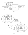
- the micro power grid system comprises an on/off-grid controller, a micro power grid control system, a battery, a bidirectional converter, a photovoltaic power generation system and loads.
- the bidirectional converter communicates with the micro power grid control system via LAN and it is controlled by the micro power grid control system, realizing the real-time control and monitor of the micro power grid control system.
- the on/off-grid controller communicates with the micro power grid control system, and the micro power grid control system sends the bidirectional converter signals to control the bidirectional converter's charging and discharging action.
- the bidirectional converter communicates with the BMS (battery management system) for the energy storage battery by way of CAN bus communication for real-time monitoring of the operation status of the battery.
- BMS battery management system
- the method for realizing on/off-grid dual-mode operation of a bidirectional converter in a micro power grid includes the following steps of: (1) the on/off-grid controller of the micro power grid detecting whether the large power grid loses power, if the large power grid loses power, the on/off-grid controller will send an instruction of preparing to go off-grid to the bidirectional converter, and meanwhile the on/off-grid controller will send an instruction of starting control strategy of going off-grid to the micro power grid control system; (2) the micro power grid control system making a comprehensive judgment on whether the micro power grid meets the off-grid conditions according to the power sources and the loads in the micro power grid, if the micro power grid meets the conditions, the on/off-grid controller will send an instruction of going off-grid to the bidirectional converter, and meanwhile the micro power grid control system will send an instruction of discharging power to the bidirectional converter to make the bidirectional converter to switch to an off-grid state and be in the operating mode of voltage
- the micro power grid control system making a judgment on whether the micro power grid meets the on-grid conditions according to the power sources and the loads in the micro power grid, if the micro power grid meets the conditions, the on/off-grid controller will send an instruction of going on-grid to the bidirectional converter, and meanwhile the micro power grid control system will send an instruction of charging/discharging to the bidirectional converter and recover all of the loads in the micro power grid, so as to make the bidirectional converter switch to an on-grid state and be in the operating mode of current source.
- the judgment made by the micro power grid control system on whether the micro power grid meets the off-grid conditions in the said step (2) is that if the on/off-grid controller has sent an off-grid signal, and other power sources in the micro power grid have stopped working, and the energy storage devices are in the normal state, and the bidirectional converter is in the operating mode of current source, the micro power grid will be considered to meet the off-grid conditions.
- the judgment made by the micro power grid control system on whether the micro power grid meets the on-grid conditions in the said step (4) is that if the on/off-grid controller has sent an on-grid signal, and the on-grid switch has been closed, and the energy storage devices are in the normal state, and the bidirectional converter is in the operating mode of voltage source, the micro power grid will be considered to meet the on-grid conditions.
- the said on/off-grid controller in the micro power grid sends instructions by the method of using two-bit binary codes and via two dry contacts which connect the on/off-grid controller and the bidirectional converter so as to realize a fast and seamless conversion between on-grid and off-grid.
- the signals for the dry contacts are expressed as two-bit binary codes, wherein 00 means "going on-grid", 01 means "preparing to go off-grid", 10 means "preparing to go on-grid” and 11 means "going off-grid”.
Landscapes
- Engineering & Computer Science (AREA)
- Power Engineering (AREA)
- Business, Economics & Management (AREA)
- Emergency Management (AREA)
- Supply And Distribution Of Alternating Current (AREA)
- Charge And Discharge Circuits For Batteries Or The Like (AREA)
Applications Claiming Priority (2)
| Application Number | Priority Date | Filing Date | Title |
|---|---|---|---|
| CN2011100973680A CN102185333B (zh) | 2011-04-19 | 2011-04-19 | 双向变流器在微电网中实现并离网双模式运行的方法 |
| PCT/CN2011/083905 WO2012142841A1 (zh) | 2011-04-19 | 2011-12-14 | 双向变流器在微电网中实现并离网双模式运行的方法 |
Publications (2)
| Publication Number | Publication Date |
|---|---|
| EP2632011A1 true EP2632011A1 (de) | 2013-08-28 |
| EP2632011A4 EP2632011A4 (de) | 2015-01-21 |
Family
ID=44571426
Family Applications (1)
| Application Number | Title | Priority Date | Filing Date |
|---|---|---|---|
| EP11863961.6A Withdrawn EP2632011A4 (de) | 2011-04-19 | 2011-12-14 | Verfahren zur implementierung eines ein/aus-gitter-doppelmodusbetriebs eines bidirektionalen wandlers in einem mikrostromgitter |
Country Status (3)
| Country | Link |
|---|---|
| EP (1) | EP2632011A4 (de) |
| CN (1) | CN102185333B (de) |
| WO (1) | WO2012142841A1 (de) |
Cited By (8)
| Publication number | Priority date | Publication date | Assignee | Title |
|---|---|---|---|---|
| CN104485689A (zh) * | 2014-12-12 | 2015-04-01 | 合肥工业大学 | 基于自适应模式切换的下垂控制方法 |
| CN105552914A (zh) * | 2016-01-27 | 2016-05-04 | 江苏大烨智能电气股份有限公司 | 一种基于电价的交直流混合微电网分层控制方法 |
| WO2019075879A1 (zh) * | 2017-10-16 | 2019-04-25 | 河海大学 | 一种交直流混合微电网运行模式转换方法 |
| US10965153B2 (en) | 2016-02-05 | 2021-03-30 | Duke Energy Corporation | Methods of microgrid communications and connection transitions |
| CN113644699A (zh) * | 2021-08-02 | 2021-11-12 | 许继集团有限公司 | 一种多变流器离网启动运行方法及装置 |
| CN113746139A (zh) * | 2021-11-01 | 2021-12-03 | 中国电力科学研究院有限公司 | 一种离网供电系统的控制方法和装置 |
| US12003105B2 (en) | 2020-04-30 | 2024-06-04 | Sungrow Power Supply Co., Ltd. | Multi-channel grid-connected power generation system and control method therefor |
| US12261447B2 (en) | 2020-12-31 | 2025-03-25 | Gree Electric Appliances, Inc. Of Zhuhai | On-grid/off-grid scheduling method and apparatus, and energy storage power supply system |
Families Citing this family (32)
| Publication number | Priority date | Publication date | Assignee | Title |
|---|---|---|---|---|
| CN102185333B (zh) * | 2011-04-19 | 2013-05-08 | 河南省电力公司电力科学研究院 | 双向变流器在微电网中实现并离网双模式运行的方法 |
| CN102420451A (zh) * | 2011-12-14 | 2012-04-18 | 北京普莱德新能源电池科技有限公司 | 移动能源系统 |
| CN102709946B (zh) * | 2012-06-05 | 2015-08-12 | 国电南瑞科技股份有限公司 | 一种微电网由并网向孤网无缝切换的方法 |
| CN102842915B (zh) * | 2012-08-23 | 2015-01-14 | 广西电网公司电力科学研究院 | 一种具备信息集成功能的并网逆变器 |
| CN103023132B (zh) * | 2012-11-19 | 2015-01-21 | 中国电力科学研究院 | 一种采用储能变流器实现被动离网无缝切换控制方法 |
| CN103490409B (zh) * | 2013-08-20 | 2015-09-30 | 国家电网公司 | 一种微网运行模式切换控制方法 |
| CN103606965B (zh) * | 2013-11-27 | 2015-10-07 | 国家电网公司 | 一种基于准实时同步信号的储能逆变器的联网控制方法 |
| CN103683283B (zh) * | 2013-12-24 | 2016-08-17 | 中国西电电气股份有限公司 | 一种微电网系统无缝切换的方法及系统 |
| CN104362665B (zh) * | 2014-09-28 | 2017-01-25 | 北京索英电气技术有限公司 | 一种微电网离网切换到并网的控制系统及控制方法 |
| CN106712074A (zh) * | 2015-11-18 | 2017-05-24 | 上海太阳能科技有限公司 | 基于电压智能跟踪技术的微电网并网控制装置 |
| CN106602719A (zh) * | 2016-09-18 | 2017-04-26 | 海南电力技术研究院 | 微电网控制系统 |
| CN106451513A (zh) * | 2016-12-08 | 2017-02-22 | 北京索英电气技术有限公司 | 一种混合式ups储能系统及其方法 |
| CN108512301A (zh) * | 2018-05-23 | 2018-09-07 | 广东电网有限责任公司 | 无缝切换移动供电装置及电力系统 |
| CN109256850A (zh) * | 2018-09-14 | 2019-01-22 | 浙江艾罗网络能源技术有限公司 | 储能变流器的并离网切换装置 |
| CN109245137B (zh) * | 2018-09-30 | 2021-11-16 | 中国科学院广州能源研究所 | 一种储能变流器的控制方法 |
| CN109524984A (zh) * | 2018-10-31 | 2019-03-26 | 北京科诺伟业科技股份有限公司 | 一种储能变流器功率调度控制方法 |
| CN109494776A (zh) * | 2018-11-30 | 2019-03-19 | 北京科诺伟业科技股份有限公司 | 储能系统并网双向变流器并离网双模式运行方法 |
| CN110401223B (zh) * | 2019-07-31 | 2021-04-27 | 珠海格力电器股份有限公司 | 光伏系统的控制方法、控制装置和光伏系统 |
| CN112636384B (zh) * | 2019-10-08 | 2023-07-18 | 维谛新能源有限公司 | 一种风力发电系统、并网控制方法及装置 |
| CN112994056B (zh) * | 2019-12-13 | 2024-04-12 | 阳光电源股份有限公司 | 离网型发电系统及其控制方法和应用系统 |
| CN112421676B (zh) * | 2020-11-09 | 2022-12-20 | 西安热工研究院有限公司 | 一种微网并网离网平滑切换电流电压相位补偿方法 |
| CN112787344B (zh) * | 2021-01-27 | 2024-11-08 | 广州智光储能科技有限公司 | 并联储能变流器离网转并网的控制方法及装置 |
| CN113890101B (zh) * | 2021-10-29 | 2024-07-09 | 阳光电源(上海)有限公司 | 一种储能改造系统及其控制方法 |
| CN114243789B (zh) * | 2021-12-30 | 2023-11-17 | 长园深瑞继保自动化有限公司 | 微电网控制方法、装置、微电网主控制器及存储介质 |
| CN114865689A (zh) * | 2022-03-31 | 2022-08-05 | 平高集团有限公司河北雄安综合能源科技分公司 | 一种储能变流器系统及其并网转离网控制方法 |
| CN115395542B (zh) * | 2022-08-04 | 2024-11-19 | 陕西华兴电能有限公司 | 一种储能变流器柜及储能系统 |
| CN115776130B (zh) * | 2022-12-29 | 2024-02-02 | 北京索英电气技术股份有限公司 | 并离网切换方法、储能变流器、储能系统和电力系统 |
| CN116418024B (zh) * | 2023-03-29 | 2024-05-10 | 江苏阿诗特能源科技股份有限公司 | 一种用于光伏逆变储能系统的离网能量管理方法 |
| US20250158415A1 (en) * | 2023-11-15 | 2025-05-15 | Delta Electronics, Inc. | Power grid systems and methods for managing the same |
| CN117639023B (zh) * | 2024-01-26 | 2024-04-05 | 深圳市健网科技有限公司 | 一种分布式储能系统自动并离网切换控制方法 |
| CN119212159B (zh) * | 2024-11-12 | 2025-06-20 | 中国电力工程顾问集团有限公司 | 一种台区级直流路灯系统 |
| CN119231603B (zh) * | 2024-11-28 | 2025-03-11 | 厦门市东港智能科技有限公司 | 一种并离网一体光伏储能系统 |
Family Cites Families (10)
| Publication number | Priority date | Publication date | Assignee | Title |
|---|---|---|---|---|
| US7116010B2 (en) * | 2002-09-17 | 2006-10-03 | Wisconsin Alumni Research Foundation | Control of small distributed energy resources |
| JP4680102B2 (ja) * | 2006-03-07 | 2011-05-11 | 川崎重工業株式会社 | 電力変換装置 |
| US7656059B2 (en) * | 2006-05-23 | 2010-02-02 | Continental Automotive Systems Us, Inc. | System and method for a power system micro grid |
| EP1965483B1 (de) * | 2007-02-27 | 2015-07-08 | SMA Solar Technology AG | Schaltung zur Verbindung einer Energieerzeugungsanlage mit dem Stromnetz |
| WO2008125697A2 (en) * | 2007-04-17 | 2008-10-23 | Timothy Patrick Cooper | A load management controller for a household electrical installation |
| CN101765959B (zh) * | 2007-05-08 | 2015-04-15 | 美国电力转换有限公司 | 交流电源能量管理 |
| CN201654170U (zh) * | 2010-04-29 | 2010-11-24 | 浙江省电力试验研究院 | 一种综合微网实验系统 |
| CN101931238A (zh) * | 2010-04-29 | 2010-12-29 | 浙江省电力试验研究院 | 基于主从策略的微网系统协调控制方法 |
| CN101873007B (zh) * | 2010-06-28 | 2012-06-27 | 北京四方继保自动化股份有限公司 | 微网继电保护、自动化一体化智能保护系统 |
| CN102185333B (zh) * | 2011-04-19 | 2013-05-08 | 河南省电力公司电力科学研究院 | 双向变流器在微电网中实现并离网双模式运行的方法 |
-
2011
- 2011-04-19 CN CN2011100973680A patent/CN102185333B/zh active Active
- 2011-12-14 EP EP11863961.6A patent/EP2632011A4/de not_active Withdrawn
- 2011-12-14 WO PCT/CN2011/083905 patent/WO2012142841A1/zh not_active Ceased
Cited By (12)
| Publication number | Priority date | Publication date | Assignee | Title |
|---|---|---|---|---|
| CN104485689A (zh) * | 2014-12-12 | 2015-04-01 | 合肥工业大学 | 基于自适应模式切换的下垂控制方法 |
| CN104485689B (zh) * | 2014-12-12 | 2016-08-24 | 合肥工业大学 | 基于自适应模式切换的下垂控制方法 |
| CN105552914A (zh) * | 2016-01-27 | 2016-05-04 | 江苏大烨智能电气股份有限公司 | 一种基于电价的交直流混合微电网分层控制方法 |
| CN105552914B (zh) * | 2016-01-27 | 2017-11-21 | 江苏大烨智能电气股份有限公司 | 一种基于电价的交直流混合微电网分层控制方法 |
| US10965153B2 (en) | 2016-02-05 | 2021-03-30 | Duke Energy Corporation | Methods of microgrid communications and connection transitions |
| WO2019075879A1 (zh) * | 2017-10-16 | 2019-04-25 | 河海大学 | 一种交直流混合微电网运行模式转换方法 |
| US12003105B2 (en) | 2020-04-30 | 2024-06-04 | Sungrow Power Supply Co., Ltd. | Multi-channel grid-connected power generation system and control method therefor |
| US12261447B2 (en) | 2020-12-31 | 2025-03-25 | Gree Electric Appliances, Inc. Of Zhuhai | On-grid/off-grid scheduling method and apparatus, and energy storage power supply system |
| CN113644699A (zh) * | 2021-08-02 | 2021-11-12 | 许继集团有限公司 | 一种多变流器离网启动运行方法及装置 |
| CN113644699B (zh) * | 2021-08-02 | 2024-04-05 | 许继集团有限公司 | 一种多变流器离网启动运行方法及装置 |
| CN113746139A (zh) * | 2021-11-01 | 2021-12-03 | 中国电力科学研究院有限公司 | 一种离网供电系统的控制方法和装置 |
| CN113746139B (zh) * | 2021-11-01 | 2022-03-08 | 中国电力科学研究院有限公司 | 一种离网供电系统的控制方法和装置 |
Also Published As
| Publication number | Publication date |
|---|---|
| CN102185333A (zh) | 2011-09-14 |
| WO2012142841A1 (zh) | 2012-10-26 |
| CN102185333B (zh) | 2013-05-08 |
| EP2632011A4 (de) | 2015-01-21 |
Similar Documents
| Publication | Publication Date | Title |
|---|---|---|
| EP2632011A1 (de) | Verfahren zur implementierung eines ein/aus-gitter-doppelmodusbetriebs eines bidirektionalen wandlers in einem mikrostromgitter | |
| CN113794216B (zh) | 一种光储充系统的参数配置方法及终端 | |
| EP3206276B1 (de) | Energiespeichersystem und verwaltungsverfahren davon | |
| CN103427430B (zh) | 一种混合储能系统在微网中的能量管理方法 | |
| CN104734322A (zh) | 一种离网新能源发电的储能充电站供电系统 | |
| CN207234421U (zh) | 分布式光伏离网供电系统 | |
| US20160218558A1 (en) | Power Supply Bus Circuit | |
| CN202712873U (zh) | 智能型家用太阳能控制逆变器 | |
| CN112046328B (zh) | 具有能量双向流动功能的电动自行车电池集中充换电系统 | |
| CN109301865B (zh) | 用于风电机组的储能系统的控制方法和通讯管理系统 | |
| US10284115B2 (en) | Inverter system | |
| US20200169089A1 (en) | Energy storage system | |
| CN111293777A (zh) | 一种用于多站融合的电力运行不间断供电系统及方法 | |
| KR102273778B1 (ko) | 배터리 팩 및 그의 구동방법 | |
| CN210297268U (zh) | 一种用于火电联合agc调频的混合储能系统 | |
| CN111406352B (zh) | 储能系统 | |
| CN202513848U (zh) | 太阳能发电阵列监控系统 | |
| CN102629777B (zh) | 直流电源备电系统 | |
| CN104009489B (zh) | 一种微电网管理系统及其管理方法 | |
| CN204119152U (zh) | 光伏供电系统用智能逆变器 | |
| CN201274412Y (zh) | 高频开关整流电源和太阳能混合配电柜中的功率控制模块 | |
| CN203387288U (zh) | 一种风力发电机的离网充电一体控制器 | |
| CN106026074A (zh) | 一种低压直流微电网实验平台 | |
| CN205945180U (zh) | 一种无线充电系统 | |
| KR20200145802A (ko) | 무순단 전원 공급이 가능한 에너지 저장 시스템 |
Legal Events
| Date | Code | Title | Description |
|---|---|---|---|
| PUAI | Public reference made under article 153(3) epc to a published international application that has entered the european phase |
Free format text: ORIGINAL CODE: 0009012 |
|
| 17P | Request for examination filed |
Effective date: 20130408 |
|
| AK | Designated contracting states |
Kind code of ref document: A1 Designated state(s): AL AT BE BG CH CY CZ DE DK EE ES FI FR GB GR HR HU IE IS IT LI LT LU LV MC MK MT NL NO PL PT RO RS SE SI SK SM TR |
|
| DAX | Request for extension of the european patent (deleted) | ||
| A4 | Supplementary search report drawn up and despatched |
Effective date: 20141218 |
|
| RIC1 | Information provided on ipc code assigned before grant |
Ipc: H02J 7/34 20060101ALI20141212BHEP Ipc: H02J 3/38 20060101AFI20141212BHEP Ipc: H02J 9/06 20060101ALI20141212BHEP |
|
| STAA | Information on the status of an ep patent application or granted ep patent |
Free format text: STATUS: THE APPLICATION IS DEEMED TO BE WITHDRAWN |
|
| 18D | Application deemed to be withdrawn |
Effective date: 20170701 |