EP2631808A1 - Network system, device server and network system control method - Google Patents
Network system, device server and network system control method Download PDFInfo
- Publication number
- EP2631808A1 EP2631808A1 EP12749006.8A EP12749006A EP2631808A1 EP 2631808 A1 EP2631808 A1 EP 2631808A1 EP 12749006 A EP12749006 A EP 12749006A EP 2631808 A1 EP2631808 A1 EP 2631808A1
- Authority
- EP
- European Patent Office
- Prior art keywords
- image
- image input
- client terminal
- input device
- web page
- Prior art date
- Legal status (The legal status is an assumption and is not a legal conclusion. Google has not performed a legal analysis and makes no representation as to the accuracy of the status listed.)
- Withdrawn
Links
Images


Classifications
-
- H—ELECTRICITY
- H04—ELECTRIC COMMUNICATION TECHNIQUE
- H04N—PICTORIAL COMMUNICATION, e.g. TELEVISION
- H04N1/00—Scanning, transmission or reproduction of documents or the like, e.g. facsimile transmission; Details thereof
- H04N1/00962—Input arrangements for operating instructions or parameters, e.g. updating internal software
- H04N1/00973—Input arrangements for operating instructions or parameters, e.g. updating internal software from a remote device, e.g. receiving via the internet instructions input to a computer terminal
-
- G—PHYSICS
- G06—COMPUTING OR CALCULATING; COUNTING
- G06F—ELECTRIC DIGITAL DATA PROCESSING
- G06F3/00—Input arrangements for transferring data to be processed into a form capable of being handled by the computer; Output arrangements for transferring data from processing unit to output unit, e.g. interface arrangements
- G06F3/12—Digital output to print unit, e.g. line printer, chain printer
- G06F3/1201—Dedicated interfaces to print systems
- G06F3/1202—Dedicated interfaces to print systems specifically adapted to achieve a particular effect
- G06F3/1203—Improving or facilitating administration, e.g. print management
- G06F3/1204—Improving or facilitating administration, e.g. print management resulting in reduced user or operator actions, e.g. presetting, automatic actions, using hardware token storing data
-
- G—PHYSICS
- G06—COMPUTING OR CALCULATING; COUNTING
- G06F—ELECTRIC DIGITAL DATA PROCESSING
- G06F3/00—Input arrangements for transferring data to be processed into a form capable of being handled by the computer; Output arrangements for transferring data from processing unit to output unit, e.g. interface arrangements
- G06F3/12—Digital output to print unit, e.g. line printer, chain printer
- G06F3/1201—Dedicated interfaces to print systems
- G06F3/1202—Dedicated interfaces to print systems specifically adapted to achieve a particular effect
- G06F3/1211—Improving printing performance
-
- G—PHYSICS
- G06—COMPUTING OR CALCULATING; COUNTING
- G06F—ELECTRIC DIGITAL DATA PROCESSING
- G06F3/00—Input arrangements for transferring data to be processed into a form capable of being handled by the computer; Output arrangements for transferring data from processing unit to output unit, e.g. interface arrangements
- G06F3/12—Digital output to print unit, e.g. line printer, chain printer
- G06F3/1201—Dedicated interfaces to print systems
- G06F3/1202—Dedicated interfaces to print systems specifically adapted to achieve a particular effect
- G06F3/1218—Reducing or saving of used resources, e.g. avoiding waste of consumables or improving usage of hardware resources
- G06F3/122—Reducing or saving of used resources, e.g. avoiding waste of consumables or improving usage of hardware resources with regard to computing resources, e.g. memory, CPU
-
- G—PHYSICS
- G06—COMPUTING OR CALCULATING; COUNTING
- G06F—ELECTRIC DIGITAL DATA PROCESSING
- G06F3/00—Input arrangements for transferring data to be processed into a form capable of being handled by the computer; Output arrangements for transferring data from processing unit to output unit, e.g. interface arrangements
- G06F3/12—Digital output to print unit, e.g. line printer, chain printer
- G06F3/1201—Dedicated interfaces to print systems
- G06F3/1223—Dedicated interfaces to print systems specifically adapted to use a particular technique
- G06F3/1224—Client or server resources management
- G06F3/1228—Printing driverless or using generic drivers
-
- G—PHYSICS
- G06—COMPUTING OR CALCULATING; COUNTING
- G06F—ELECTRIC DIGITAL DATA PROCESSING
- G06F3/00—Input arrangements for transferring data to be processed into a form capable of being handled by the computer; Output arrangements for transferring data from processing unit to output unit, e.g. interface arrangements
- G06F3/12—Digital output to print unit, e.g. line printer, chain printer
- G06F3/1201—Dedicated interfaces to print systems
- G06F3/1223—Dedicated interfaces to print systems specifically adapted to use a particular technique
- G06F3/1237—Print job management
- G06F3/1244—Job translation or job parsing, e.g. page banding
- G06F3/1247—Job translation or job parsing, e.g. page banding by conversion to printer ready format
-
- G—PHYSICS
- G06—COMPUTING OR CALCULATING; COUNTING
- G06F—ELECTRIC DIGITAL DATA PROCESSING
- G06F3/00—Input arrangements for transferring data to be processed into a form capable of being handled by the computer; Output arrangements for transferring data from processing unit to output unit, e.g. interface arrangements
- G06F3/12—Digital output to print unit, e.g. line printer, chain printer
- G06F3/1201—Dedicated interfaces to print systems
- G06F3/1223—Dedicated interfaces to print systems specifically adapted to use a particular technique
- G06F3/1237—Print job management
- G06F3/1268—Job submission, e.g. submitting print job order or request not the print data itself
-
- G—PHYSICS
- G06—COMPUTING OR CALCULATING; COUNTING
- G06F—ELECTRIC DIGITAL DATA PROCESSING
- G06F3/00—Input arrangements for transferring data to be processed into a form capable of being handled by the computer; Output arrangements for transferring data from processing unit to output unit, e.g. interface arrangements
- G06F3/12—Digital output to print unit, e.g. line printer, chain printer
- G06F3/1201—Dedicated interfaces to print systems
- G06F3/1278—Dedicated interfaces to print systems specifically adapted to adopt a particular infrastructure
- G06F3/1285—Remote printer device, e.g. being remote from client or server
- G06F3/1287—Remote printer device, e.g. being remote from client or server via internet
-
- G—PHYSICS
- G06—COMPUTING OR CALCULATING; COUNTING
- G06F—ELECTRIC DIGITAL DATA PROCESSING
- G06F3/00—Input arrangements for transferring data to be processed into a form capable of being handled by the computer; Output arrangements for transferring data from processing unit to output unit, e.g. interface arrangements
- G06F3/12—Digital output to print unit, e.g. line printer, chain printer
- G06F3/1201—Dedicated interfaces to print systems
- G06F3/1278—Dedicated interfaces to print systems specifically adapted to adopt a particular infrastructure
- G06F3/1285—Remote printer device, e.g. being remote from client or server
- G06F3/1289—Remote printer device, e.g. being remote from client or server in server-client-printer device configuration, e.g. the server does not see the printer
-
- G—PHYSICS
- G06—COMPUTING OR CALCULATING; COUNTING
- G06F—ELECTRIC DIGITAL DATA PROCESSING
- G06F3/00—Input arrangements for transferring data to be processed into a form capable of being handled by the computer; Output arrangements for transferring data from processing unit to output unit, e.g. interface arrangements
- G06F3/12—Digital output to print unit, e.g. line printer, chain printer
- G06F3/1293—Printer information exchange with computer
-
- H—ELECTRICITY
- H04—ELECTRIC COMMUNICATION TECHNIQUE
- H04L—TRANSMISSION OF DIGITAL INFORMATION, e.g. TELEGRAPHIC COMMUNICATION
- H04L67/00—Network arrangements or protocols for supporting network services or applications
- H04L67/01—Protocols
- H04L67/02—Protocols based on web technology, e.g. hypertext transfer protocol [HTTP]
- H04L67/025—Protocols based on web technology, e.g. hypertext transfer protocol [HTTP] for remote control or remote monitoring of applications
-
- H—ELECTRICITY
- H04—ELECTRIC COMMUNICATION TECHNIQUE
- H04L—TRANSMISSION OF DIGITAL INFORMATION, e.g. TELEGRAPHIC COMMUNICATION
- H04L67/00—Network arrangements or protocols for supporting network services or applications
- H04L67/01—Protocols
- H04L67/10—Protocols in which an application is distributed across nodes in the network
-
- H—ELECTRICITY
- H04—ELECTRIC COMMUNICATION TECHNIQUE
- H04N—PICTORIAL COMMUNICATION, e.g. TELEVISION
- H04N1/00—Scanning, transmission or reproduction of documents or the like, e.g. facsimile transmission; Details thereof
- H04N1/00127—Connection or combination of a still picture apparatus with another apparatus, e.g. for storage, processing or transmission of still picture signals or of information associated with a still picture
-
- H—ELECTRICITY
- H04—ELECTRIC COMMUNICATION TECHNIQUE
- H04N—PICTORIAL COMMUNICATION, e.g. TELEVISION
- H04N1/00—Scanning, transmission or reproduction of documents or the like, e.g. facsimile transmission; Details thereof
- H04N1/00127—Connection or combination of a still picture apparatus with another apparatus, e.g. for storage, processing or transmission of still picture signals or of information associated with a still picture
- H04N1/00204—Connection or combination of a still picture apparatus with another apparatus, e.g. for storage, processing or transmission of still picture signals or of information associated with a still picture with a digital computer or a digital computer system, e.g. an internet server
-
- H—ELECTRICITY
- H04—ELECTRIC COMMUNICATION TECHNIQUE
- H04N—PICTORIAL COMMUNICATION, e.g. TELEVISION
- H04N1/00—Scanning, transmission or reproduction of documents or the like, e.g. facsimile transmission; Details thereof
- H04N1/00127—Connection or combination of a still picture apparatus with another apparatus, e.g. for storage, processing or transmission of still picture signals or of information associated with a still picture
- H04N1/00204—Connection or combination of a still picture apparatus with another apparatus, e.g. for storage, processing or transmission of still picture signals or of information associated with a still picture with a digital computer or a digital computer system, e.g. an internet server
- H04N1/00209—Transmitting or receiving image data, e.g. facsimile data, via a computer, e.g. using e-mail, a computer network, the internet, I-fax
- H04N1/00222—Transmitting or receiving image data, e.g. facsimile data, via a computer, e.g. using e-mail, a computer network, the internet, I-fax details of image data generation or reproduction, e.g. scan-to-email or network printing
- H04N1/00225—Transmitting or receiving image data, e.g. facsimile data, via a computer, e.g. using e-mail, a computer network, the internet, I-fax details of image data generation or reproduction, e.g. scan-to-email or network printing details of image data generation, e.g. scan-to-email or network scanners
-
- H—ELECTRICITY
- H04—ELECTRIC COMMUNICATION TECHNIQUE
- H04N—PICTORIAL COMMUNICATION, e.g. TELEVISION
- H04N1/00—Scanning, transmission or reproduction of documents or the like, e.g. facsimile transmission; Details thereof
- H04N1/00127—Connection or combination of a still picture apparatus with another apparatus, e.g. for storage, processing or transmission of still picture signals or of information associated with a still picture
- H04N1/00204—Connection or combination of a still picture apparatus with another apparatus, e.g. for storage, processing or transmission of still picture signals or of information associated with a still picture with a digital computer or a digital computer system, e.g. an internet server
- H04N1/00236—Connection or combination of a still picture apparatus with another apparatus, e.g. for storage, processing or transmission of still picture signals or of information associated with a still picture with a digital computer or a digital computer system, e.g. an internet server using an image reading or reproducing device, e.g. a facsimile reader or printer, as a local input to or local output from a computer
- H04N1/00238—Connection or combination of a still picture apparatus with another apparatus, e.g. for storage, processing or transmission of still picture signals or of information associated with a still picture with a digital computer or a digital computer system, e.g. an internet server using an image reading or reproducing device, e.g. a facsimile reader or printer, as a local input to or local output from a computer using an image reproducing device as a local output from a computer
-
- H—ELECTRICITY
- H04—ELECTRIC COMMUNICATION TECHNIQUE
- H04N—PICTORIAL COMMUNICATION, e.g. TELEVISION
- H04N1/00—Scanning, transmission or reproduction of documents or the like, e.g. facsimile transmission; Details thereof
- H04N1/00127—Connection or combination of a still picture apparatus with another apparatus, e.g. for storage, processing or transmission of still picture signals or of information associated with a still picture
- H04N1/00204—Connection or combination of a still picture apparatus with another apparatus, e.g. for storage, processing or transmission of still picture signals or of information associated with a still picture with a digital computer or a digital computer system, e.g. an internet server
- H04N1/00244—Connection or combination of a still picture apparatus with another apparatus, e.g. for storage, processing or transmission of still picture signals or of information associated with a still picture with a digital computer or a digital computer system, e.g. an internet server with a server, e.g. an internet server
-
- H—ELECTRICITY
- H04—ELECTRIC COMMUNICATION TECHNIQUE
- H04N—PICTORIAL COMMUNICATION, e.g. TELEVISION
- H04N1/00—Scanning, transmission or reproduction of documents or the like, e.g. facsimile transmission; Details thereof
- H04N1/0035—User-machine interface; Control console
- H04N1/00405—Output means
- H04N1/00408—Display of information to the user, e.g. menus
- H04N1/00464—Display of information to the user, e.g. menus using browsers, i.e. interfaces based on mark-up languages
-
- H—ELECTRICITY
- H04—ELECTRIC COMMUNICATION TECHNIQUE
- H04N—PICTORIAL COMMUNICATION, e.g. TELEVISION
- H04N2201/00—Indexing scheme relating to scanning, transmission or reproduction of documents or the like, and to details thereof
- H04N2201/0008—Connection or combination of a still picture apparatus with another apparatus
- H04N2201/001—Sharing resources, e.g. processing power or memory, with a connected apparatus or enhancing the capability of the still picture apparatus
-
- H—ELECTRICITY
- H04—ELECTRIC COMMUNICATION TECHNIQUE
- H04N—PICTORIAL COMMUNICATION, e.g. TELEVISION
- H04N2201/00—Indexing scheme relating to scanning, transmission or reproduction of documents or the like, and to details thereof
- H04N2201/0077—Types of the still picture apparatus
- H04N2201/0081—Image reader
-
- H—ELECTRICITY
- H04—ELECTRIC COMMUNICATION TECHNIQUE
- H04N—PICTORIAL COMMUNICATION, e.g. TELEVISION
- H04N2201/00—Indexing scheme relating to scanning, transmission or reproduction of documents or the like, and to details thereof
- H04N2201/0077—Types of the still picture apparatus
- H04N2201/0082—Image hardcopy reproducer
Definitions
- a network system preferably also has a printer that connects over a network to the client terminal, wherein: a printing control script that operates on the web browser and controls printing related to the web page is also embedded in the web page acquired by the web page acquisition unit; the client terminal includes a drawing process unit that is controlled by the image input control script to draw an image acquired by the image acquisition unit in a specific drawing area, a print data generating unit that is controlled by the printing control script in conjunction with a print operation on the web page to generate print data that converts the image data drawn in the drawing area to a form that can be processed by the printer, and a print data transmission unit that is controlled by the printing control script to send the generated print data to the printer; and the printer includes a print data receiving unit that receives the print data sent by the print data transmission unit, and a print control unit that controls a printing process based on the received print data.
- a printing control script 23 for controlling printing related to the web page 21
- a scanner control script 24 JavaScript (R), an image control script that controls image input from the scanner 3 are included (embedded) in the web page 21, and the client terminal 2 executes a printing process and an image acquisition process (image input process) by running the printing control script 23 and scanner control script 24 through the web browser 56 (on the web page 21) .
- the printing control script 23 and scanner control script 24 can be contained on different web pages 21, or both may be contained on a single web page 21.
- the client terminal 2 has a web page acquisition means 71 (web page acquisition unit), image acquisition request transmission means 72 (image acquisition request transmission unit), image acquisition means 73 (image acquisition unit), drawing process means 74 (drawing process unit), print data generation means 75 (print data generation unit), print process request transmission means 76 (print process request transmission unit), and event processing means 77 (selection window display unit, stop operation request transmission unit).
Landscapes
- Engineering & Computer Science (AREA)
- General Engineering & Computer Science (AREA)
- Theoretical Computer Science (AREA)
- Human Computer Interaction (AREA)
- Physics & Mathematics (AREA)
- Signal Processing (AREA)
- General Physics & Mathematics (AREA)
- Multimedia (AREA)
- Computing Systems (AREA)
- Computer Networks & Wireless Communication (AREA)
- Mathematical Physics (AREA)
- Information Transfer Between Computers (AREA)
- Facsimiles In General (AREA)
- Accessory Devices And Overall Control Thereof (AREA)
Abstract
Description
- The present invention relates to a network system to which one or more image input devices are connected for use, a device server, and a network system control method.
- Devices such as scanners and printers are commonly used connected over a network to a computer, but device drivers for controlling the devices are required in order to use the devices. The device drivers are generally installed to the computer connected to the devices (see, for example, PTL1).
-
- [PTL1]
JP-A-2002-251347 - However, because device driver operation depends on the OS (operating system) of the computer to which the device driver is installed, the user must install the device driver corresponding to the OS installed on the user's computer. However, the task of determining the OS that is used and installing software (device drivers) can be difficult for users that are not computer-savvy, and can be a significant burden. Reinstalling device drivers is also necessarywhen the computer is replaced. Another problem is that the device manufacturer must develop a device driver for each different computer OS, thus increasing development costs.
- With consideration for the foregoing problem, an object of the present invention is to provide a network system enabling controlling an image input device without requiring a device driver that depends on the computer environment, to a device server, and to a network system control method.
- A network system according to the invention is a network system that includes a web application server on which a web application operates, one or more client terminals that use a web browser to access the web application server, and an image input device that operates in conjunction with operation of the client terminal, wherein at least the web application server and the client terminal, and the client terminal and the image input device, are respectively connected over a network, the network system characterized by: the client terminal including a web page acquisition unit that gets from the web application server a web page having an embedded image input control script that operates at least on the web browser and controls image input from the image input device, an image acquisition request transmission unit that is controlled by the image input control script to send an image acquisition request to the image input device when a specific operation is performed on the acquired web page, and an image acquisition unit that is controlled by the image input control script to acquire an image from the image input device as a response to the image acquisition request; and the image input device including an image acquisition request receiving unit that receives the image acquisition request, and an image transmission unit that sends an image to the client terminal based on the received image acquisition request.
- A network system control method according to the invention is a control method for a network system that includes a web application server on which a web application operates, one or more client terminals that use a web browser to access the web application server, and an image input device that operates in conjunction with operation of the client terminal, wherein at least the web application server and the client terminal, and the client terminal and the image input device, are respectively connected over a network, the control method of the network system characterized by: the client terminal executing a web page acquisition step of getting from the web application server a web page having an embedded image input control script that operates at least on the web browser and controls image input from the image input device, an image acquisition request transmission step that is controlledby the image input control script to send an image acquisition request to the image input device when a specific operation is performed on the acquiredwebpage, and an image acquisition step that is controlled by the image input control script to acquire an image from the image input device as a response to the image acquisition request; and the image input device executing an image acquisition request reception step to receive the image acquisition request, and an image transmission step to send an image to the client terminal based on the received image acquisition request.
- These configurations enable acquiring a specific image from an image input device by means of an image input control script that is embedded in a web page. More specifically, because the image input device can be controlled using a web browser (in a web page), an image input device can be controlled by simply installing a web browser to the client terminal, and there is no need to install a device driver (a driver for the image input device) on each client terminal as there is with the related art. The need to develop a plurality of device drivers for different operating systems is also eliminated for the manufacturer of the image input device, and related development costs can therefore be reduced.
Furthermore, because a web browser is typically already installed on most modern client terminals (computers including personal computers and smartphones), even users that are not computer-savvy can easily use the image input device without knowing the operating environment (the type of operating system) of the terminal being used by the user. Note that scanners and digital cameras are examples of image input devices. - In a network system according to another aspect of the invention, the client terminal preferably also has a selection window display unit that is controlled by the image input control script to display a selection window for selecting whether or not to stop operation of the image input device when a change event that changes the web page occurs while the image input device is operating, and a stop operation request transmission unit that is controlled by the image input control script to send a stop operation request to the image input device when stopping operation of the image input device is selected in the selection window.
- When the operator (user) performs an action to change the web page, this aspect of the invention informs the user that the image input device is operating and causes the user to select whether or not to stop operation of the image input device. Because the invention controls the image input device with a script (image input control script), the image input control script is lost if the web page changes while the image input device is operating (processing). By displaying a selection window when an event that changes the web page occurs, this aspect of the invention can prevent a process frombeing interrupted unintentionally as a result of the web page being accidentally changed by the operator (user).
- A network system according to another aspect of the invention preferably also has a printer that connects over a network to the client terminal, wherein: a printing control script that operates on the web browser and controls printing related to the web page is also embedded in the web page acquired by the web page acquisition unit; the client terminal includes a drawing process unit that is controlled by the image input control script to draw an image acquired by the image acquisition unit in a specific drawing area, a print data generating unit that is controlled by the printing control script in conjunction with a print operation on the web page to generate print data that converts the image data drawn in the drawing area to a form that can be processed by the printer, and a print data transmission unit that is controlled by the printing control script to send the generated print data to the printer; and the printer includes a print data receiving unit that receives the print data sent by the print data transmission unit, and a print control unit that controls a printing process based on the received print data.
- This aspect of the invention can print images acquired by the image input device from the printer (can control printing by the printer) by means of the printing control script embedded in the web page. More specifically, because printing by the printer can be controlled by a script that operates on the web browser (operates in a web page), installing a web browser on the client terminal is sufficient, and there is no need to install a device driver (printer driver) on each client terminal as there is with the related art.
- A device server according to the invention has the parts of the image input device in the network system described above, and is used connected to the image input device.
- Further preferably, the device server of the invention also has the parts of the printer in the network system described above, and is used connected to the printer.
- With these configurations the invention can be achieved by connecting the device server without changing the image input device or printer (without incorporating a special function). The device server can be achieved by an interface board (interface device) that can connect to the image input device or printer.
-
-
FIG. 1 shows the configuration of a network system according to an embodiment of the invention. -
FIG. 2 is a block diagram showing the functional configuration of the network system. -
FIG. 3 is a flow chart describing steps in an image acquisition process and printing process on the network system. -
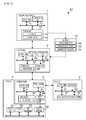
FIG. 4 is a flow chart of steps in a process for handling an event that changes the web page during the image acquisition process. - A network system, device driver, and method of controlling a network system according to this embodiment of the invention are describedbelowwith reference to the accompanying figures. The network system according to this embodiment is a system that can run an image input process using a web browser without installing a dedicated device driver on the client terminal. Note that a scanner is used as an example of an image input device in this embodiment.
-
FIG. 1 shows the configuration of the network system SY. As shown in the figure, the network system SY includes aweb application server 1, aclient terminal 2 that accesses theweb application server 1, a scanner 3 (image input device) that scans a specific document based on a request from theclient terminal 2, aprinter 4 that prints based on a request from theclient terminal 2, and a removable interface board 5 (device driver) that is installed to theprinter 4. Theweb application server 1 andclient terminal 2 are connected so that they can communicate over the Internet. Theclient terminal 2 andinterface board 5 are connected so that they can communicate over a LAN. Thescanner 3 is connected through an communication unit 33 disposed to theinterface board 5 installed in theprinter 4. Theclient terminal 2 can thus communicate through theinterface board 5 with thescanner 3 andprinter 4. - Note that the method of connecting to the network (Internet or LAN) may be by wire or wireless.
FIG. 1 also shows only oneclient terminal 2,scanner 3, andprinter 4, but the invention is not so limited and any number of these can be used. - The
web application server 1 has the hardware configuration of a general computer in addition to acontrol unit 11,storage unit 12, andcommunication unit 13. The main parts of thecontrol unit 11 include a CPU (central processing unit), ROM (read-only memory), and RAM (random access memory). The CPU runs a program stored in ROM, and controls operation of theweb application server 1. ROM stores control data and a control program enabling the CPU to execute various processes. RAM is used as working memory for the CPU to execute different processes. Thestorage unit 12 stores anHTTP server 14 andweb application 15. - The
communication unit 13 is an interface for communicating with the client terminal 2 (web browser 66) . Communication between theweb application server 1 andclient terminal 2 is controlled by theHTTP server 14 using Hypertext Transfer Protocol (HTTP) . More specifically, theweb application server 1 receives an HTTP request from the client terminal 2 (web browser 66), and based on the URL (Uniform Resource Locator) contained in the HTTP request, sends aweb page 21 provided by theweb application 15 to theclient terminal 2. - As described in detail below, in addition to a page control script 22 (JavaScript (R)) for controlling the
web page 21, a printing control script 23 (JavaScript (R)) for controlling printing related to theweb page 21, and a scanner control script 24 (JavaScript (R), an image control script) that controls image input from thescanner 3, are included (embedded) in theweb page 21, and theclient terminal 2 executes a printing process and an image acquisition process (image input process) by running theprinting control script 23 and scannercontrol script 24 through the web browser 56 (on the web page 21) . Theprinting control script 23 andscanner control script 24 can be contained ondifferent web pages 21, or both may be contained on asingle web page 21. - The
interface board 5 includes acontrol unit 31,storage unit 32, communication unit 33, andboard interface 34. Thecontrol unit 31 primarily includes a CPU and RAM. The CPU runs a program stored in thestorage unit 32 and controls theinterface board 5. RAM is used as working memory for the CPU to execute processes. Thestorage unit 32 is, for example, nonvolatile memory (such as flash ROM), and stores control data and control programs for the CPU to execute the processes. Thestorage unit 32 also anHTTP server 35. - The
board interface 34 is a port for installation to theprinter 4, and communication with the printer 3A passes through thisboard interface 34. The communication unit 33 is an interface for communicating with the client terminal 2 (web browser 66) andscanner 3, and comprises a group of interfaces compatible with different kinds of connections, such as a LAN interface and a USB interface. - The
HTTP server 35 handles communication between theinterface board 5 and the client terminal 2 (web browser 66) using HTTP. More specifically, when a process request for the scanner 3 (such as an image acquisition request or stop scanning request), or a process request for the printer 4 (such as a printing process request), is sent from theclient terminal 2 to the service endpoint address (URI) assigned to theinterface board 5, theinterface board 5 sends a process command to thescanner 3 orprinter 4 based on the received process request (as described in detail below). - The
scanner 3 primarily includes acontrol unit 41,storage unit 42,image reader 43, andcommunication unit 44. Thecontrol unit 41 primarily includes a CPU and RAM. The CPU runs a program stored in thestorage unit 42 and controls thescanner 3. RAM is used as working memory for the CPU to execute processes. Thestorage unit 42 is, for example, nonvolatile memory (such as flash ROM), and stores control data and control programs for the CPU to execute the processes. - The
image reader 43 optically reads (scans) documents, such as text or photographs, placed on the document table (not shown) as controlled by the CPU. Thecommunication unit 44 is an interface for communicating with theinterface board 5, and comprises a group of interfaces compatible with different kinds of connections, such as a LAN interface and a USB interface. Thescanner 3 receives an image acquisition command from theclient terminal 2 through theinterface board 5, scans the document, and then sends the result of scanning to theclient terminal 2. - The
printer 4 primarily includes acontrol unit 51,storage unit 52,print mechanism 53, andprinter interface 54. Thecontrol unit 51 primarily includes a CPU and RAM. The CPU runs a program stored in thestorage unit 52 and controls theprinter 4. RAM is used as working memory for the CPU to execute processes. Thestorage unit 52 is, for example, nonvolatile memory (such as flash ROM), and stores control data and control programs for the CPU to execute the processes. - The
print mechanism 53 includes a paper feedmechanism, printhead, and paper cutting mechanism, and performs a printing operation as controlled by the CPU. Any desired printing method may be used, including an inkjet or laser printing method. Theboard interface 54 is a port that connects to the interface board 5 (board interface 34), and communicates with theinterface board 5. Theprinter 4 receives print data sent from theclient terminal 2 through theinterface board 5, and controls theprint mechanism 53 to print based on the received print data. - The
client terminal 2 primarily includes acontrol unit 61,storage unit 62,display unit 63, operatingunit 64, andcommunication unit 65. Thecontrol unit 61 primarily includes a CPU and RAM. The CPU runs a program stored in thestorage unit 62 and controls theclient terminal 2. RAM is used as working memory for the CPU to run processes. Thestorage unit 62 is, for example, a HDD (hard disk drive) or nonvolatile memory (such as flash ROM), and stores control data and control programs used by the CPU to execute different processes. Thestorage unit 62 also stores aweb browser 66. - The
display unit 63 displays aweb page 21 acquired (downloaded) by theweb browser 66, and displays windows for reporting events accompanying operations performed in theweb browser 66, as well as windows for configuring settings and selections. These windows could be displayed in theweb page 21 displayed by theweb browser 66, or displayed in anew web page 21. The operatingunit 64 is an operating means for performing input operations (such as inputting text and drawing figures), and making selection/decision operations, image acquisition operations (scanning operations),and printing operations, in aweb page 21 displayed by theweb browser 66. Note that thedisplay unit 63 andoperating unit 64 may be rendered as separate elements, or rendered in unison by, for example, using a touch screen panel as thedisplay unit 63. - The
communication unit 65 is an interface for communication with theweb application server 1 andinterface board 5, and theclient terminal 2 uses theweb browser 66 to communicate with the devices. Theweb browser 66 is a simple browser (standard browser) with no plugin modules, and theclient terminal 2 uses thisweb browser 66 to access the network-connected (Internet-connected)web application server 1 and receiveweb pages 21 provided by theweb application 15. - 1 The
web page 21 includes apage control script 22,printing control script 23, andscanner control script 24 as described above, and when an image acquisition operation (such as pressing a scan button or clicking on a specific area) is performed by the user in the web browser 66 (on the web page 21), theweb browser 66 runs thescanner control script 24 embedded in theweb page 21, acquires (inputs) the image data from thescanner 3 through theinterface board 5, and draws the image data in a specific drawing area. This drawing area is a drawing canvas (HTML5 canvas element) defined (set) in thepage control script 22, for example. - When the user issues a print command (such as by pressing a print button) on the
web page 21, theweb browser 66 runs theprinting control script 23 embedded in theweb page 21, generates print data from the image data written in the drawing area, and sends the print data to theprinter 4 through theinterface board 5. - The
client terminal 2 may be any computer on which theweb browser 66 runs, and may be a mobile terminal (such as a cellular telephone or smartphone) or personal computer (PC), for example. - The functional configuration of the network system SY is described next with reference to
FIG. 2 . Theclient terminal 2 has a web page acquisition means 71 (web page acquisition unit), image acquisition request transmission means 72 (image acquisition request transmission unit), image acquisition means 73 (image acquisition unit), drawing process means 74 (drawing process unit), print data generation means 75 (print data generation unit), print process request transmission means 76 (print process request transmission unit), and event processing means 77 (selection window display unit, stop operation request transmission unit). - The web
page acquisition unit 71 primarily includes thecontrol unit 61 andweb browser 66, accesses the web application server 1 (web application 15) through theweb browser 66, and gets the desired web page 21 (theweb page 21 containing thepage control script 22,printing control script 23, and scanner control script 24). - The image acquisition request transmission means 72 primarily includes the
control unit 61 andscanner control script 24, and runs thescanner control script 24 and sends an image acquisition request (scan request) to thescanner 3 when the user performs an image acquisition operation in theweb page 21. More specifically, the image acquisition request transmission means 72 sends an image acquisition request containing scanner identification information (information such as a scanner ID or communication port) identifying ascanner 3 and scanning configuration information (such as the scanning area, resolution, color/grayscale/monochrome setting, the image processing method to use for scanning, and a time limit to complete processing) to the service endpoint address of theinterface board 5. The service endpoint address of theinterface board 5 and the scanner identification information are previously set in thescanner control script 24. The scanning configuration information is set by, for example, displaying a setup window on theweb page 21 and the user inputting the settings in the setup window when the user performs an image acquisition operation. - The image acquisition means 73 primarily includes the
control unit 61 andscanner control script 24, and acquires the image captured by thescanner 3 in response to the image acquisition request through theinterface board 5. Note that the image acquisition means 73 interrupts image acquisition when theweb page 21 is changed (when an unload event occurs) during scanning (while an image is being received). This is because thescanner control script 24, which is an element of the image acquisition means 73, is embedded in theweb page 21, and thescanner control script 24 is lost when theweb page 21 is changed. - The main parts of the drawing process means 74 are the
control unit 61,page control script 22, andscanner control script 24, and the drawing process means 74 draws the image acquired from the scanner 3 (the image scanned by the scanner 3) in the drawing area by running thescanner control script 24. When the user performs an input operation on theweb page 21 displayed by theweb browser 66, the drawing process means 74 edits (processes) the image acquired from thescanner 3 or merges the acquired image with another image (an image selected by the user) by drawing the result of the user input (the result of inputting text or selecting an image, for example) in the drawing area by running thepage control script 22. - The main parts of the print data generation means 75 are the
control unit 61 andprinting control script 23. When the user performs a print operation (such as pressing a print button) on theweb page 21, the print data generation means 75 runs theprinting control script 23 to convert the image data drawn in the drawing area to a form that can be processed by theprinter 4, generating print data (such as a raster image command, bitmap file, or XML print data). The print data generation means 75 also temporarily stores the generated print data in a specific storage area (storage unit 62) . Web storage, for example, can be used to temporarily store the print data. - The
control unit 61 andprinting control script 23 are the main parts of the print process request transmission means 76, which sends a printing process request to theprinter 4. More specifically, the print process request transmission means 76 sends a printing process request containing printer identification information (such as the printer ID or communication port) identifying theprinter 4, and the print data temporarily stored (generated) by the print data generation means 75, to the service endpoint address of theinterface board 5. Note that the service endpoint address of theinterface board 5 and the printer identification information are previously set in theprinting control script 23. If theweb page 21 is changed (if an unload event occurs) while the print data is being sent, the print process request transmission means 76 interrupts transmission. This is because theprinting control script 23, which is an element of the print process request transmission means 76, is embedded in theweb page 21, and theprinting control script 23 is lost when theweb page 21 is changed. - The event processing means 77 primarily includes the
control unit 61,display unit 63,page control script 22,printing control script 23, andscanner control script 24, and reports various events to the user. More specifically, when a user operation causes an event that changes the displayed web page 21 (a beforeunload event) while thescanner control script 24 is running and an image is being acquired from the scanner 3 (while the scanner is operating), the event processing means 77 presents a message indicating that thescanner 3 is operating and displays an operation selection window (selection window display unit) for selecting whether or not to stopscanner 3 operation (whether to stop or continue scanner operation) . If the user chooses to continue scanner operation in this operation selection window, changing theweb page 21 is stopped. However, if the user chooses to stop scanner operation in this operation selection window, the event processing means 77 sends a request to stopscanner 3 operation (including scanner identification information) to theinterface board 5, and displays a notice that the image acquisition process was interrupted (stop operation request transmission unit). - When a user operation causes an event that changes the displayed
web page 21 while theprinting control script 23 is running and the printing process is executing (while print data is being sent), the event processing means 77 presents a change confirmation window for selecting whether or not to change theweb page 21. If the option that cancels changing the web page is selected by the user in this change confirmation window, changing theweb page 21 is stopped. However, if the option that changes the web page is selected by the user in the change confirmation window, the event processing means 77 displays a notice indicating that print data transmission was interrupted. - The
interface board 5 has a process request receiving means 81 (image acquisition request receiving unit, print data receiving unit), process command means 82 (print control unit), and board-side image transmission means 83 (image transmission unit). The process request receiving means 81 primarily includes thecontrol unit 31 andHTTP server 35, and receives process requests (such as the printing process request, image acquisition request, and stop operation request) from the client terminal 2 (printing control script 23 and scanner control script 24). The process command means 82 primarily includes thecontrol unit 31, and sends commands to thescanner 3 orprinter 4 based on the process request received by the process request receiving means 81. More specifically, when the process request from theclient terminal 2 is a printing process request, the process command means 82 sends print data to theprinter 4 specified by the printer identification information. When the process request from theclient terminal 2 is an image acquisition request, the process command means 82 sends a command based on the image acquisition request to thescanner 3 specified by the scanner identification information. When the process request from theclient terminal 2 is a stop operation request, the process command means 82 sends a command based on the stop operation request to thescanner 3 specified by the scanner identification information. The board-side image transmission means 83 primarily includes thecontrol unit 31 andHTTP server 35, and receives and sends the image captured by thescanner 3 to theclient terminal 2. - The
scanner 3 primarily includes an image reading means 91, scanner-side image transmission means 92, and image reading interruption means 93. The image reading means 91 primarily includes acontrol unit 41 andimage reader 43, and based on an image acquisition command (image acquisition request) received from theinterface board 5, scans the document set on the document table with theimage reader 43. The scanner-side image transmission means 92 primarily includes thecontrol unit 41, and sends the image captured by the image reading means 91 to theinterface board 5. The image reading interruption means 93 primarily includes the thecontrol unit 41 andimage reader 43, and based on a stop operation command (stop operation request) received from theinterface board 5 stops (interrupts) scanning by theimage reader 43. - The
printer 4 has a printer-side print data receiving means 101 and printing means 102. The printer-side print data receiving means 101 primarily includes acontrol unit 51, and receives print data sent from theclient terminal 2 through theinterface board 5. The printing means 102 primarily includes thecontrol unit 51 andprint mechanism 53, and prints images based on the received print data. The printing means 102 prints in the printing process after all print data sent from theclient terminal 2 has been received. More specifically, the print data sent from theclient terminal 2 is temporarily stored to a specific storage area in thestorage unit 52, and the stored print data is then read and printed. - Steps in the image acquisition process (image input process) and printing process in this network system SY are described next with reference to the flow chart in
FIG. 3 . First, the client terminal 2 (control unit 61) accesses the web application server 1 (web application 15) based on user operations in theweb browser 66, gets the desired web page 21 (theweb page 21 containing thepage control script 22,printing control script 23, and scanner control script 24), and displays theweb page 21 in the web browser 66 (S01, web page acquisition step). - When the user then performs an image acquisition operation on the web page 21 (such as clicking a scan button displayed on the web page 21), the
client terminal 2 acquires an image acquisition command accompanying the image acquisition operation by means of the page control script 22 (S02). Triggered by acquiring this image acquisition command, thescanner control script 24 is called from thepage control script 22, and the image acquisition process starts. - More specifically, the
client terminal 2 sends an image acquisition request to the interface board 5 (the service endpoint address of the interface board 5) by executing the scanner control script 24 (S03, image acquisition request transmission step). Identification information (scanner identification information) for the desiredscanner 3, and the configuration information for scanning operation, are contained in this image acquisition request. - The interface board 5 (control unit 31) then receives the image acquisition request (S04, image acquisition request reception step), and issues a command (scan command) to the specified
scanner 3 based on the image acquisition request (S05). The scanner 3 (control unit 41) that received the scan command from theinterface board 5 controls theimage reader 43 to start the document scanning process (S06), and sends the scanned image through theinterface board 5 to the client terminal 2 (S07, S08, image transmission step). - Once the image that was captured by the
scanner 3 is received from the interface board 5 (S09, image acquisition step), theclient terminal 2 draws the image in the drawing area (S10). After the image is drawn and the user then performs a specific input operation on theweb page 21, theclient terminal 2 receives the input operation according to thepage control script 22 embedded in theweb page 21, and draws the result of the received input operation in the drawing area. More specifically, processes such as editing the image acquired from thescanner 3 or merging the image with another image selected by the user can be performed. Process control when an event that changes theweb page 21 occurs as a result of user operation of the browser during the image acquisition process (while scanning) is described below with reference toFIG. 4 . - If the user calls a printing operation from the
web page 21 after the image is drawn in S10 (such as by clicking a print button on the web page 21), theclient terminal 2 receives a print command resulting from the printing operation from the page control script 22 (S11). Triggered by getting this print command, theprinting control script 23 is called from thepage control script 22, and the printing process starts. - More specifically, the
client terminal 2 image processes (such as digitizing and gathering) the image drawn in the drawing area according to the printing control script 23 (S12), converts the image data to print data in a form that can be processed by the printer 4 (S1), and saves the resulting print data in the storage unit 62 (S14). Steps S13 and S14 repeat until print data generation is completed, that is, until all image data drawn in the drawing area is converted to print data (S15 returns No). - When print data generation is completed (S15 returns Yes), the
client terminal 2 sends a printing process request to the interface board 5 (the service endpoint address of the interface board 5) by running the printing control script 23 (S16). Identification information (printer identification information) for the desiredprinter 4, and the print data stored in thestorage unit 62, are included in this printing process request. - When the printing process request from the
client terminal 2 is received (S17), theinterface board 5 sends the print data to theprinter 4 specified by the printer identification information (S18). After the print data is received from the interface board 5 (S19), the printer 4 (control unit 51) saves the print data in the storage unit 52 (S20) . Steps S19 and S20 repeat until all print data is received (S21 returns No). After all print data is received (S21 returns Yes), theprinter 4 reads and prints based on the saved print data (prints an image) (S22). - The steps performed when an event that changes the
web page 21 is generated while theclient terminal 2 is receiving an image from the scanner 3 (during the scanning process) is described next with reference to the flow chart inFIG. 4 . Note that a special process is not performed when an event that changes theweb page 21 is not generated, and description thereof is omitted in the following description of the flow chart inFIG. 4 . - The client terminal 2 (control unit 61) first starts the image acquisition process of the
scanner 3 by means of the scanner control script 24 (S31). If an event that changes the displayed web page 21 (that is, theweb page 21 in which the currently executingscanner control script 24 is embedded) to another page is generated by the user using the web browser 66 (S32 returns Yes), theclient terminal 2 continues image acquisition by running thescanner control script 24 while simultaneously displaying a message indicating that thescanner 3 is operating and an operation selection window for selecting whether or not to stop the scanning operation of the scanner 3 (S33). - If continuing the scanning operation is selected by the user in this operation selection window (S34 returns No), the
client terminal 2 continues the image acquisition process by running thescanner control script 24, and when all image data has been received (S35 returns Yes), ends the image acquisition process (S36). However, if stopping the scanning operation is selected by the user in this operation selection window (S34 returns Yes), theclient terminal 2 sends a stop operation request to the scanner 3 (S37), interrupts the image acquisition process (S38) in conjunction with losing thescanner control script 24, and displays a message indicating that the image acquisition process was stopped (S39). By thus displaying an operation selection window when an event that changes theweb page 21 occurs, unintended interruption of the image acquisition process (image input from the scanner 3) resulting from the user accidentally changing the web page can be prevented. - As described above, this embodiment enables acquiring a specific image from a scanner 3 (image input device) using a scanner control script 24 (image input control script) embedded in a
web page 21. More specifically, because ascanner 3 can be controlled using a web browser 66 (from within a web page 21), thescanner 3 can be controlled by simply installing aweb browser 66 on theclient terminal 2, and, unlike with the related art, there is no need to install a device driver (a scanner driver) on eachclient terminal 2. There is also no need for the manufacturer supplying thescanner 3 to develop plural device drivers for different different operating systems, and the related development cost can be reduced. - Furthermore, because a
web browser 66 is typically already installed on most modern client terminals 2 (computers including personal computers and smartphones), even users that are not computer-savvy can easily use thescanner 3 without knowing the operating environment (the type of operating system) of the terminal being used by the user. - This embodiment is described using a
scanner 3 as an example of an image input device, but the invention is not so limited. For example, a digital camera (camera) could be used as an image input device. In this implementation, an image input control script that controls (requests a process) selecting files and acquiring images stored in the camera, and controls (requests a process) acquiring a directory of files stored in the camera, is embedded in theweb page 21 and used to control the camera. - The identification information that identifies (specifies) the
scanner 3 orprinter 4 is predefined in thescanner control script 24 andprinting control script 23 in this embodiment, but the invention is not so limited. For example, whenplural scanners 3 andprinters 4 are connected and can be used, the user could be made to select the desiredscanner 3 orprinter 4 from a device list (a list of scanners or a list of printers), and identification information for the selectedscanner 3 orprinter 4 sent to theinterface board 5 by the corresponding control script. - This embodiment describes a configuration in which the
interface board 5 is installed to theprinter 4, but the invention is not so limited and a configuration having theinterface board 5 installed to thescanner 3 is also conceivable. In this implementation an interface for connecting to theboard interface 34 of theinterface board 5 is disposed to thescanner 3, and an interface that communicates with the communication unit 33 of theinterface board 5 is disposed to theprinter 4. - The means (functions) of the
interface board 5 in this embodiment can alternatively be rendered by a common personal computer (device server). Further alternatively, a configuration in which the above means are disposed to thescanner 3 andprinter 4 is also conceivable. - Elements of the network system SY (
client terminal 2 and interface board 5) described above can also be provided as a program. This program can also be provided stored on a storage medium (not shown in the figure). Examples of such storage media include CD-ROM, flash ROM, memory cards (Compact Flash (R), smart media, memory sticks), Compact Discs, magneto-optical discs, Digital Versatile Discs, and floppy disks. - The hardware configuration of the network system SY and process steps are also not limited to the foregoing embodiment, and can be changed as desired without departing from the scope of the invention.
-
- 1
- web application server
- 2
- client terminal
- 3
- scanner
- 4
- printer
- 5
- interface board
- 15
- web application
- 21
- web page
- 22
- page control script
- 23
- printing control script
- 66
- web browser
- 71
- web page acquisition means
- 72
- image acquisition request transmission means
- 73
- image acquisition means
- 74
- drawing process means
- 75
- print data generation means
- 76
- print process request transmission means
- 77
- event processing means
- 81
- process request receiving means
- 82
- process command means
- 83
- board-side image transmission means
- SY
- network system
Claims (6)
- A network system that includes a web application server on which a web application operates, one or more client terminals that use a web browser to access the web application server, and an image input device that operates in conjunction with operation of the client terminal, wherein at least the web application server and the client terminal, and the client terminal and the image input device, are respectively connected over a network, the network system characterized by:the client terminal comprising
a web page acquisition unit that gets from the web application server a web page having an embedded image input control script that operates at least on the web browser and controls image input from the image input device,
an image acquisition request transmission unit that is controlledby the image input control script to send an image acquisition request to the image input device when a specific operation is performed on the acquired web page, and
an image acquisition unit that is controlled by the image input control script to acquire an image from the image input device as a response to the image acquisition request; andthe image input device comprising
an image acquisition request receiving unit that receives the image acquisition request, and
an image transmission unit that sends an image to the client terminal based on the received image acquisition request. - The network system described in claim 1, wherein:the client terminal further comprises
a selection window display unit that is controlled by the image input control script to display a selection window for selecting whether or not to stop operation of the image input device when a change event that changes the web page occurs while the image input device is operating, and
a stop operation request transmission unit that is controlled by the image input control script to send a stop operation request to the image input device when stopping operation of the image input device is selected in the selection window. - A network system characterized by further comprising a printer that connects over a network to the client terminal, wherein:a printing control script that operates on the web browser and controls printing related to the web page is also embedded in the web page acquired by the web page acquisition unit;the client terminal includes
a drawing process unit that is controlled by the image input control script to draw an image acquired by the image acquisition unit in a specific drawing area,
a print data generating unit that is controlled by the printing control script in conjunction with a print operation on the web page to generate print data that converts the image data drawn in the drawing area to a form that can be processed by the printer, and
a print data transmission unit that is controlled by the printing control script to send the generated print data to the printer; andthe printer includes
a print data receiving unit that receives the print data sent by the print data transmission unit, and
a print control unit that controls a printing process based on the received print data. - A device server that is characterized by comprising the parts of the image input device in the network system described in any of claims 1 to 3, and is used connected to the image input device.
- The device server described in claim 4 that is characterized by further comprising the parts of the printer in the network system described in claim 3, and is used connected to the printer.
- Control method for a network system that includes a web application server on which a web application operates, one or more client terminals that use a web browser to access the web application server, and an image input device that operates in conjunction with operation of the client terminal, wherein at least the web application server and the client terminal, and the client terminal and the image input device, are respectively connected over a network, the control method of the network system characterized by:the client terminal executing
a web page acquisition step of getting from the web application server a web page having an embedded image input control script that operates at least on the web browser and controls image input from the image input device,
an image acquisition request transmission step that is controlledby the image input control script to send an image acquisition request to the image input device when a specific operation is performed on the acquired web page, and
an image acquisition step that is controlled by the image input control script to acquire an image from the image input device as a response to the image acquisition request; andthe image input device executing
an image acquisition request reception step to receive the image acquisition request, and
an image transmission step to send an image to the client terminal based on the received image acquisition request.
Applications Claiming Priority (2)
| Application Number | Priority Date | Filing Date | Title |
|---|---|---|---|
| JP2011034278A JP5732896B2 (en) | 2011-02-21 | 2011-02-21 | Network system and network system control method |
| PCT/JP2012/000701 WO2012114660A1 (en) | 2011-02-21 | 2012-02-02 | Network system, device server and network system control method |
Publications (2)
| Publication Number | Publication Date |
|---|---|
| EP2631808A1 true EP2631808A1 (en) | 2013-08-28 |
| EP2631808A4 EP2631808A4 (en) | 2014-12-24 |
Family
ID=46720456
Family Applications (1)
| Application Number | Title | Priority Date | Filing Date |
|---|---|---|---|
| EP12749006.8A Withdrawn EP2631808A4 (en) | 2011-02-21 | 2012-02-02 | NETWORK SYSTEM, DEVICE SERVER, AND NETWORK SYSTEM CONTROL PROCEDURE |
Country Status (5)
| Country | Link |
|---|---|
| US (3) | US9398074B2 (en) |
| EP (1) | EP2631808A4 (en) |
| JP (1) | JP5732896B2 (en) |
| CN (2) | CN103380419B (en) |
| WO (1) | WO2012114660A1 (en) |
Cited By (1)
| Publication number | Priority date | Publication date | Assignee | Title |
|---|---|---|---|---|
| EP2799999A4 (en) * | 2013-01-02 | 2015-12-09 | Seiko Epson Corp | DEVICE CONTROL SYSTEM, PRINTER AND METHOD FOR CONTROLLING A DEVICE CONTROL SYSTEM |
Families Citing this family (8)
| Publication number | Priority date | Publication date | Assignee | Title |
|---|---|---|---|---|
| JP6136911B2 (en) * | 2013-12-17 | 2017-05-31 | ブラザー工業株式会社 | Information processing program and terminal device |
| CN105743961A (en) * | 2014-12-30 | 2016-07-06 | 深圳中兴网信科技有限公司 | Scanning method, terminal and Web server |
| CN105335304A (en) * | 2015-10-10 | 2016-02-17 | 远光软件股份有限公司 | Scanner drive control system and control method thereof |
| CN107733947A (en) * | 2016-08-11 | 2018-02-23 | 中国移动通信集团江苏有限公司 | Image acquiring method, apparatus and system |
| US20180131822A1 (en) * | 2016-11-04 | 2018-05-10 | Api, Llc | System and method for digital scanning and importing of documents |
| JP2020088593A (en) * | 2018-11-26 | 2020-06-04 | セイコーエプソン株式会社 | Electronic device, image reading method, and print processing method |
| JP6953582B1 (en) * | 2020-05-22 | 2021-10-27 | 株式会社Cygames | Content playback program and content playback device |
| CN115037844A (en) * | 2021-03-04 | 2022-09-09 | 株式会社理光 | Scanning processing apparatus, method, scanning system, and computer-readable medium |
Family Cites Families (38)
| Publication number | Priority date | Publication date | Assignee | Title |
|---|---|---|---|---|
| US5220674A (en) * | 1987-07-17 | 1993-06-15 | Digital Equipment Corporation | Local area print server for requesting and storing required resource data and forwarding printer status message to selected destination |
| US6289371B1 (en) * | 1998-09-30 | 2001-09-11 | Hewlett-Packard Company | Network scan server support method using a web browser |
| WO2000078001A2 (en) * | 1999-06-11 | 2000-12-21 | Microsoft Corporation | General api for remote control of devices |
| SE9904131L (en) | 1999-11-15 | 2001-05-16 | Intermec Ptc Ab | Printer |
| US20020082919A1 (en) | 2000-05-01 | 2002-06-27 | Michael Landau | System method and article of manufacture for affiliate tracking for the dissemination of promotional and marketing material via e-mail |
| US20020062259A1 (en) * | 2000-09-26 | 2002-05-23 | Katz James S. | Server-side system responsive to peripherals |
| US20020065950A1 (en) * | 2000-09-26 | 2002-05-30 | Katz James S. | Device event handler |
| US20020062287A1 (en) * | 2000-09-26 | 2002-05-23 | Katz James S. | Peripheral device detection and notification |
| US6566697B1 (en) | 2000-11-28 | 2003-05-20 | Dalsa, Inc. | Pinned photodiode five transistor pixel |
| US7065564B2 (en) | 2000-12-22 | 2006-06-20 | Canon Kabushiki Kaisha | Network system, method and apparatus for processing information, and control program |
| JP2002176675A (en) * | 2000-12-06 | 2002-06-21 | Seiko Epson Corp | Data transmission system and method |
| US20040039934A1 (en) * | 2000-12-19 | 2004-02-26 | Land Michael Z. | System and method for multimedia authoring and playback |
| US20060129933A1 (en) * | 2000-12-19 | 2006-06-15 | Sparkpoint Software, Inc. | System and method for multimedia authoring and playback |
| JP4617038B2 (en) | 2000-12-22 | 2011-01-19 | キヤノン株式会社 | Information processing apparatus, method, and control program |
| US7117504B2 (en) | 2001-07-10 | 2006-10-03 | Microsoft Corporation | Application program interface that enables communication for a network software platform |
| US20030078965A1 (en) | 2001-08-22 | 2003-04-24 | Cocotis Thomas A. | Output management system and method for enabling printing via wireless devices |
| US20030079030A1 (en) | 2001-08-22 | 2003-04-24 | Cocotis Thomas A. | Output management system and method for enabling access to private network resources |
| US7055169B2 (en) * | 2002-04-19 | 2006-05-30 | Opentv, Inc. | Supporting common interactive television functionality through presentation engine syntax |
| US20080177994A1 (en) * | 2003-01-12 | 2008-07-24 | Yaron Mayer | System and method for improving the efficiency, comfort, and/or reliability in Operating Systems, such as for example Windows |
| CN100382073C (en) * | 2003-03-27 | 2008-04-16 | 佳能株式会社 | Image forming system, control method of image forming system, and storage medium |
| JP4311738B2 (en) * | 2004-09-15 | 2009-08-12 | キヤノン株式会社 | Image forming apparatus, control method therefor, and computer program |
| JP2007311915A (en) | 2006-05-16 | 2007-11-29 | Ricoh Co Ltd | Image reading system, image reading method, and program for causing computer to execute the method |
| US8555288B2 (en) * | 2006-05-17 | 2013-10-08 | Teradata Us, Inc. | Managing database utilities to improve throughput and concurrency |
| JP4868955B2 (en) | 2006-06-22 | 2012-02-01 | 株式会社リコー | Image processing apparatus, information processing apparatus, server apparatus, display control system, and display control method |
| JP4909044B2 (en) * | 2006-12-14 | 2012-04-04 | キヤノン株式会社 | License management system and control method thereof, image forming apparatus and control method thereof |
| JP2008152545A (en) * | 2006-12-18 | 2008-07-03 | Seiko Epson Corp | Print processing system and print method |
| JP4555926B2 (en) * | 2007-02-01 | 2010-10-06 | サイレックス・テクノロジー株式会社 | Scanner automatic connection program |
| US20090013044A1 (en) * | 2007-07-05 | 2009-01-08 | Microsoft Corporation | Techniques for managing annotation transformations for context changes |
| JP5040486B2 (en) * | 2007-07-09 | 2012-10-03 | セイコーエプソン株式会社 | Network system and program |
| JP4989350B2 (en) * | 2007-08-06 | 2012-08-01 | キヤノン株式会社 | Adapter and control method thereof |
| JP5284023B2 (en) * | 2007-10-05 | 2013-09-11 | キヤノン株式会社 | Information processing apparatus, control method, and control program |
| US8639214B1 (en) | 2007-10-26 | 2014-01-28 | Iwao Fujisaki | Communication device |
| US20090268229A1 (en) | 2008-04-23 | 2009-10-29 | Tanna Marie Richardson | Multifunction Peripheral Browser Control for Application Integration |
| US20100057586A1 (en) * | 2008-09-04 | 2010-03-04 | China Software Venture | Offer Reporting Apparatus and Method |
| JP5344575B2 (en) * | 2009-02-17 | 2013-11-20 | キヤノン株式会社 | Image forming apparatus |
| JP5335470B2 (en) * | 2009-02-18 | 2013-11-06 | キヤノン株式会社 | Image processing apparatus, server apparatus, control method thereof, and program |
| JP5582721B2 (en) * | 2009-05-13 | 2014-09-03 | キヤノン株式会社 | System operating in Web environment and control method thereof |
| JP5591040B2 (en) * | 2009-12-11 | 2014-09-17 | キヤノン株式会社 | Image processing apparatus, image processing apparatus control method, and program |
-
2011
- 2011-02-21 JP JP2011034278A patent/JP5732896B2/en active Active
-
2012
- 2012-02-02 EP EP12749006.8A patent/EP2631808A4/en not_active Withdrawn
- 2012-02-02 WO PCT/JP2012/000701 patent/WO2012114660A1/en not_active Ceased
- 2012-02-02 CN CN201280009629.1A patent/CN103380419B/en active Active
- 2012-02-02 US US14/000,380 patent/US9398074B2/en active Active
- 2012-02-02 CN CN201510530808.5A patent/CN105120125B/en active Active
-
2016
- 2016-05-27 US US15/166,778 patent/US9977639B2/en active Active
-
2017
- 2017-01-24 US US15/413,826 patent/US10063731B2/en active Active
Cited By (7)
| Publication number | Priority date | Publication date | Assignee | Title |
|---|---|---|---|---|
| EP2799999A4 (en) * | 2013-01-02 | 2015-12-09 | Seiko Epson Corp | DEVICE CONTROL SYSTEM, PRINTER AND METHOD FOR CONTROLLING A DEVICE CONTROL SYSTEM |
| US9274730B2 (en) | 2013-01-02 | 2016-03-01 | Seiko Epson Corporation | Client device using a web browser to control a periphery device via a printer |
| US9280305B2 (en) | 2013-01-02 | 2016-03-08 | Seiko Epson Corporation | Client device using a markup language to control a periphery device via a printer |
| US9495121B2 (en) | 2013-01-02 | 2016-11-15 | Seiko Epson Corporation | Client device using a markup language to control a periphery device via a point-of-sale printer |
| US10043169B2 (en) | 2013-01-02 | 2018-08-07 | Seiko Epson Corporation | Point-of-sale printer interpreting a markup language from a client device to control a scanner using scanner-control commands |
| US10108949B2 (en) | 2013-01-02 | 2018-10-23 | Seiko Epson Corporation | Printer communicating with a computing device that has access to a target-device script that initiates a control object to control a target device |
| US10402809B2 (en) | 2013-01-02 | 2019-09-03 | Seiko Epson Corporation | Point-of-sale printer interpreting a markup language from a client device to control a scanner using scanner-control commands |
Also Published As
| Publication number | Publication date |
|---|---|
| CN105120125B (en) | 2018-05-04 |
| CN103380419A (en) | 2013-10-30 |
| US9398074B2 (en) | 2016-07-19 |
| US10063731B2 (en) | 2018-08-28 |
| US20160342371A1 (en) | 2016-11-24 |
| JP2012173910A (en) | 2012-09-10 |
| CN105120125A (en) | 2015-12-02 |
| JP5732896B2 (en) | 2015-06-10 |
| EP2631808A4 (en) | 2014-12-24 |
| CN103380419B (en) | 2015-09-16 |
| US9977639B2 (en) | 2018-05-22 |
| US20170134602A1 (en) | 2017-05-11 |
| US20130332520A1 (en) | 2013-12-12 |
| WO2012114660A1 (en) | 2012-08-30 |
Similar Documents
| Publication | Publication Date | Title |
|---|---|---|
| US9977639B2 (en) | Network system, device server, and network system control method | |
| US10015356B2 (en) | Information processing system and information processing method | |
| US8964217B2 (en) | Information processing system and method for acquiring workflow from management apparatus using user terminal address | |
| CN108628934B (en) | Image processing apparatus, image processing system, image processing method, and recording medium | |
| US8526021B2 (en) | Server, control method thereof and storage medium for assisting image processing apparatus in error recovery | |
| US20160344881A1 (en) | Information processing system, information processing method and computer program product | |
| US20120314245A1 (en) | Image processing apparatus, image processing system, method for controlling the same, and storage medium therefor | |
| US12028490B2 (en) | Server for providing a setting screen with previously used settings to a client apparatus for image transmission | |
| CN103946853A (en) | Image forming apparatus, server apparatus, and information processing apparatus | |
| JP5673177B2 (en) | Network system, network system printing control method, and client terminal | |
| US9116640B2 (en) | Image processing apparatus, display method, and storage medium | |
| US11991331B2 (en) | Server, method of controlling the server, and storage medium | |
| US20040239956A1 (en) | Image forming apparatus, image forming method, and information processing apparatus for conducting print instruction thereto | |
| JP2015143974A (en) | Processing device, processing method and program | |
| JP5728994B2 (en) | Network system, interface board, network system print processing method, and client terminal | |
| JP2020166466A (en) | Program combinations and programs | |
| JP6152913B2 (en) | Image input control script and client terminal control method | |
| JP5935921B2 (en) | Client terminal, client terminal control method, and image input control program | |
| JP5900593B2 (en) | Network system control method, print control script control method, and print control script | |
| US20250039318A1 (en) | Image processing system, image processing method, and non-transitory computer readable medium | |
| JP2020096340A (en) | Image processing apparatus, image processing system, image processing method, and Web browser program | |
| JP2018086841A (en) | Printer, control method for the same, and interface board | |
| JP6260682B2 (en) | Printer and printer control method | |
| JP5900592B2 (en) | Network system, client terminal, and client terminal control method | |
| JP6065132B2 (en) | Print control script and client terminal control method |
Legal Events
| Date | Code | Title | Description |
|---|---|---|---|
| PUAI | Public reference made under article 153(3) epc to a published international application that has entered the european phase |
Free format text: ORIGINAL CODE: 0009012 |
|
| 17P | Request for examination filed |
Effective date: 20130524 |
|
| AK | Designated contracting states |
Kind code of ref document: A1 Designated state(s): AL AT BE BG CH CY CZ DE DK EE ES FI FR GB GR HR HU IE IS IT LI LT LU LV MC MK MT NL NO PL PT RO RS SE SI SK SM TR |
|
| DAX | Request for extension of the european patent (deleted) | ||
| A4 | Supplementary search report drawn up and despatched |
Effective date: 20141120 |
|
| RIC1 | Information provided on ipc code assigned before grant |
Ipc: G06F 3/12 20060101ALI20141114BHEP Ipc: H04L 29/08 20060101ALI20141114BHEP Ipc: G06F 13/00 20060101AFI20141114BHEP Ipc: B41J 29/38 20060101ALI20141114BHEP Ipc: H04N 1/00 20060101ALI20141114BHEP |
|
| STAA | Information on the status of an ep patent application or granted ep patent |
Free format text: STATUS: EXAMINATION IS IN PROGRESS |
|
| 17Q | First examination report despatched |
Effective date: 20180618 |
|
| STAA | Information on the status of an ep patent application or granted ep patent |
Free format text: STATUS: THE APPLICATION HAS BEEN WITHDRAWN |
|
| 18W | Application withdrawn |
Effective date: 20190410 |