EP2631691A1 - Optical fiber terminal, optical fiber cable with terminal, optical connector, optical fiber cable with connector, and connection structure - Google Patents
Optical fiber terminal, optical fiber cable with terminal, optical connector, optical fiber cable with connector, and connection structure Download PDFInfo
- Publication number
- EP2631691A1 EP2631691A1 EP11834402.7A EP11834402A EP2631691A1 EP 2631691 A1 EP2631691 A1 EP 2631691A1 EP 11834402 A EP11834402 A EP 11834402A EP 2631691 A1 EP2631691 A1 EP 2631691A1
- Authority
- EP
- European Patent Office
- Prior art keywords
- optical fiber
- element wire
- optical
- ferrule
- terminal
- Prior art date
- Legal status (The legal status is an assumption and is not a legal conclusion. Google has not performed a legal analysis and makes no representation as to the accuracy of the status listed.)
- Withdrawn
Links
- 239000013307 optical fiber Substances 0.000 title claims abstract description 320
- 230000003287 optical effect Effects 0.000 title claims abstract description 104
- 239000011248 coating agent Substances 0.000 claims abstract description 27
- 238000000576 coating method Methods 0.000 claims abstract description 27
- 238000003780 insertion Methods 0.000 claims abstract description 26
- 230000037431 insertion Effects 0.000 claims abstract description 26
- 239000000835 fiber Substances 0.000 claims description 6
- 239000011347 resin Substances 0.000 claims description 6
- 229920005989 resin Polymers 0.000 claims description 6
- 238000004891 communication Methods 0.000 description 14
- 238000000034 method Methods 0.000 description 7
- 239000004734 Polyphenylene sulfide Substances 0.000 description 5
- 229920000069 polyphenylene sulfide Polymers 0.000 description 5
- VYPSYNLAJGMNEJ-UHFFFAOYSA-N Silicium dioxide Chemical compound O=[Si]=O VYPSYNLAJGMNEJ-UHFFFAOYSA-N 0.000 description 4
- 238000005452 bending Methods 0.000 description 4
- 229920001707 polybutylene terephthalate Polymers 0.000 description 4
- 230000005540 biological transmission Effects 0.000 description 3
- 238000005253 cladding Methods 0.000 description 3
- 239000002184 metal Substances 0.000 description 3
- 239000000853 adhesive Substances 0.000 description 2
- 230000001070 adhesive effect Effects 0.000 description 2
- 230000000694 effects Effects 0.000 description 2
- 238000012423 maintenance Methods 0.000 description 2
- 238000004519 manufacturing process Methods 0.000 description 2
- 239000004033 plastic Substances 0.000 description 2
- -1 polybutylene terephthalate Polymers 0.000 description 2
- 230000008054 signal transmission Effects 0.000 description 2
- 239000000377 silicon dioxide Substances 0.000 description 2
- 229920000271 Kevlar® Polymers 0.000 description 1
- 239000004760 aramid Substances 0.000 description 1
- 229920003235 aromatic polyamide Polymers 0.000 description 1
- 125000004122 cyclic group Chemical group 0.000 description 1
- 239000000428 dust Substances 0.000 description 1
- 239000011521 glass Substances 0.000 description 1
- 238000007689 inspection Methods 0.000 description 1
- 239000004761 kevlar Substances 0.000 description 1
- SQEHCNOBYLQFTG-UHFFFAOYSA-M lithium;thiophene-2-carboxylate Chemical compound [Li+].[O-]C(=O)C1=CC=CS1 SQEHCNOBYLQFTG-UHFFFAOYSA-M 0.000 description 1
- 238000012986 modification Methods 0.000 description 1
- 230000004048 modification Effects 0.000 description 1
- 229920006122 polyamide resin Polymers 0.000 description 1
- 230000005236 sound signal Effects 0.000 description 1
- XLYOFNOQVPJJNP-UHFFFAOYSA-N water Substances O XLYOFNOQVPJJNP-UHFFFAOYSA-N 0.000 description 1
Images






Classifications
-
- G—PHYSICS
- G02—OPTICS
- G02B—OPTICAL ELEMENTS, SYSTEMS OR APPARATUS
- G02B6/00—Light guides; Structural details of arrangements comprising light guides and other optical elements, e.g. couplings
- G02B6/24—Coupling light guides
- G02B6/36—Mechanical coupling means
- G02B6/38—Mechanical coupling means having fibre to fibre mating means
- G02B6/3807—Dismountable connectors, i.e. comprising plugs
- G02B6/3833—Details of mounting fibres in ferrules; Assembly methods; Manufacture
- G02B6/3855—Details of mounting fibres in ferrules; Assembly methods; Manufacture characterised by the method of anchoring or fixing the fibre within the ferrule
- G02B6/3858—Clamping, i.e. with only elastic deformation
-
- G—PHYSICS
- G02—OPTICS
- G02B—OPTICAL ELEMENTS, SYSTEMS OR APPARATUS
- G02B6/00—Light guides; Structural details of arrangements comprising light guides and other optical elements, e.g. couplings
- G02B6/24—Coupling light guides
- G02B6/241—Light guide terminations
-
- G—PHYSICS
- G02—OPTICS
- G02B—OPTICAL ELEMENTS, SYSTEMS OR APPARATUS
- G02B6/00—Light guides; Structural details of arrangements comprising light guides and other optical elements, e.g. couplings
- G02B6/24—Coupling light guides
- G02B6/36—Mechanical coupling means
- G02B6/38—Mechanical coupling means having fibre to fibre mating means
- G02B6/3807—Dismountable connectors, i.e. comprising plugs
- G02B6/3869—Mounting ferrules to connector body, i.e. plugs
-
- G—PHYSICS
- G02—OPTICS
- G02B—OPTICAL ELEMENTS, SYSTEMS OR APPARATUS
- G02B6/00—Light guides; Structural details of arrangements comprising light guides and other optical elements, e.g. couplings
- G02B6/24—Coupling light guides
- G02B6/36—Mechanical coupling means
- G02B6/38—Mechanical coupling means having fibre to fibre mating means
- G02B6/3807—Dismountable connectors, i.e. comprising plugs
- G02B6/3887—Anchoring optical cables to connector housings, e.g. strain relief features
- G02B6/38875—Protection from bending or twisting
-
- G—PHYSICS
- G02—OPTICS
- G02B—OPTICAL ELEMENTS, SYSTEMS OR APPARATUS
- G02B6/00—Light guides; Structural details of arrangements comprising light guides and other optical elements, e.g. couplings
- G02B6/24—Coupling light guides
- G02B6/36—Mechanical coupling means
- G02B6/38—Mechanical coupling means having fibre to fibre mating means
- G02B6/3807—Dismountable connectors, i.e. comprising plugs
- G02B6/3887—Anchoring optical cables to connector housings, e.g. strain relief features
- G02B6/3888—Protection from over-extension or over-compression
-
- G—PHYSICS
- G02—OPTICS
- G02B—OPTICAL ELEMENTS, SYSTEMS OR APPARATUS
- G02B6/00—Light guides; Structural details of arrangements comprising light guides and other optical elements, e.g. couplings
- G02B6/24—Coupling light guides
- G02B6/36—Mechanical coupling means
- G02B6/38—Mechanical coupling means having fibre to fibre mating means
- G02B6/3807—Dismountable connectors, i.e. comprising plugs
- G02B6/3873—Connectors using guide surfaces for aligning ferrule ends, e.g. tubes, sleeves, V-grooves, rods, pins, balls
- G02B6/3874—Connectors using guide surfaces for aligning ferrule ends, e.g. tubes, sleeves, V-grooves, rods, pins, balls using tubes, sleeves to align ferrules
- G02B6/3878—Connectors using guide surfaces for aligning ferrule ends, e.g. tubes, sleeves, V-grooves, rods, pins, balls using tubes, sleeves to align ferrules comprising a plurality of ferrules, branching and break-out means
- G02B6/3879—Linking of individual connector plugs to an overconnector, e.g. using clamps, clips, common housings comprising several individual connector plugs
Definitions
- the present invention relates to an optical fiber terminal, an optical fiber cable with a terminal, an optical connector, an optical fiber cable with a connector, and a connection structure.
- optical fiber cables instead of conventional metal cables (refer to Patent Literatures 1 and 2).
- the optical fiber cable is free from a problem of emitting noise therearound due to increase in the communication speed, and thus is a signal transmission path suitable for high-speed and large-capacity information communication.
- the optical fiber cable is provided at an end thereof with an optical connector.
- the optical connector includes a terminal (optical fiber terminal) including a ferrule and the like to be attached to the end of the optical fiber cable, and a housing having a structure for being connected to another optical connector or the like.
- an optical connector is also provided on a device performing communication, and the optical fiber cable can be connected with the device performing communication by connecting the optical connectors to each other.
- the optical connectors also achieve a connection between optical fiber cables.
- the connection between optical fiber cables is called wire-to-wire connection.
- a device performing communication through the wire harnesses is disposed at each component unit of the vehicle, such as a roof portion, a floor portion, an engine and surroundings thereof, and an instrument panel and surroundings thereof. Therefore, among components in the wire harnesses connecting between the communication devices disposed at the respective component units, particularly the optical connector used for the wire-to-wire connection can be repeatedly mounted and dismounted many times, for example, in the assembly process and the mounting process during the vehicle production, and in the inspection and maintenance, and thus can be subjected to strong impacts such as tensions at those occasions.
- the optical connector is also subjected to vibration, impacts, and the like while the vehicle is running. Accordingly, particularly the optical connectors used in a vehicle are particularly required to be strong against vibration and impact.
- the present invention has been made in view of the description above, and it is an object of the present invention to provide an optical fiber terminal which can achieve an optical connector that is strong against vibration and impact, an optical fiber cable with the terminal, the optical connector, an optical fiber cable with the connector, and a connection structure.
- an optical fiber terminal configured to be attached to an end of an optical fiber cable.
- the optical fiber cable includes: an optical fiber element wire having an optical fiber covered by an element wire coating; a tensile member disposed along a longitudinal direction of the optical fiber element wire; and a coating portion that covers the optical fiber element wire and the tensile member.
- the optical fiber terminal includes: a ferrule that has an insertion hole for inserting and fixing the optical fiber element wire, and a front end face on which a front end face of the optical fiber inserted in the insertion hole is configured to be exposed; and a tensile member fixing member for fixing the tensile member to the ferrule.
- the tensile member is made of resin fibers;
- the ferrule includes a base portion for placing thereon the tensile member at an opposite end to the front end face of the ferrule; and
- the tensile member fixing member is a clinching member configured to be fitted into the base portion of the ferrule to clinch the base portion of the ferrule together with the tensile member placed on the base portion.
- the ferrule includes an optical fiber fixing member having a groove for holding the optical fiber element wire, and an open hole formed on a side face of the ferrule, the open hole having a depth at which the inserted optical fiber element wire is at least exposed.
- the optical fiber fixing member is configured to be inserted into the open hole of the ferrule, and the inserted optical fiber element wire is configured to be held by the groove to fix the inserted optical fiber element wire.
- An optical fiber cable with a terminal includes: an optical fiber cable including an optical fiber element wire having an optical fiber covered by an element wire coating, a tensile member disposed along a longitudinal direction of the optical fiber element wire, and a coating portion that covers the optical fiber element wire and the tensile member; and the optical fiber terminal according to any one of the above inventions that is attached to an end of the optical fiber cable.
- An optical connector according to the present invention includes: the optical fiber terminal according to any one of the above inventions; and a housing that holds the optical fiber terminal.
- the housing includes a fixing structure for fixing the optical connector to another optical connector in a removable manner.
- the fixing structure is a latch structure for engaging the optical connector with another optical connector.
- the optical connector of the present invention further includes an optical fiber terminal fixing member for fixing the optical fiber terminal to the housing.
- the ferrule includes a groove on an outer circumference of the ferrule, and the optical fiber terminal fixing member is configured to be fitted into the groove.
- the housing includes a restricting surface for restricting the optical fiber terminal from moving toward the front end face of the ferrule.
- the ferrule includes a flange portion that abuts against the restricting surface of the housing to restrict the optical fiber terminal from moving toward the front end face of the ferrule.
- An optical fiber cable with a connector includes: an optical fiber cable including an optical fiber element wire having an optical fiber covered by an element wire coating, a tensile member disposed along a longitudinal direction of the optical fiber element wire, and a coating portion that covers the optical fiber element wire and the tensile member; and the optical connector according to any one of the above inventions that is attached to an end of the optical fiber cable.
- a connection structure of an optical connector according to the present invention includes at least two ferrules, into each of which an optical fiber is incorporated, the ferrules being arranged in a longitudinal direction in a manner opposed to each other.
- the connection structure restricts the ferrules from moving in directions coming close to each other and maintains a shortest distance between connection end faces of the at least two ferrules at 30 ⁇ m to 300 ⁇ m.
- a tensile member is directly fixed to a ferrule so as to be integrated therewith, an optical connector that is strong against vibration and impact can be achieved.
- FIG. 1 is a view schematically illustrating an optical fiber cable with terminals in which the optical fiber terminals according to the first embodiment are attached to an end of the optical fiber cable.
- optical fiber terminals 10 are attached to respective pieces of the end of an optical fiber cable 1 to be attached to a duplex optical connector, and provided each with a ferrule 2, a clinching ring 3 serving as a fixing member for a tensile member, and a protection boot 4.
- the ferrule 2 includes an optical fiber fixing member 2e.
- the two optical fiber terminals 10 have the same structure as each other, and therefore, one of the optical fiber terminals 10 will be described below.
- FIG. 2 is a schematic exploded view of the optical fiber cable with terminals illustrated in FIG. 1 .
- the optical fiber cable 1 includes an optical fiber element wire 1a composed of an optical fiber 1aa and an element wire coating portion 1ab that is formed along the longitudinal direction of the outer circumference of the optical fiber 1aa to clad the optical fiber 1aa.
- the optical fiber cable 1 also includes a tensile member 1b disposed along the longitudinal direction of the outer circumference of the optical fiber element wire 1a, and further includes an outer coating portion 1c covering the outer circumference of the tensile member 1b along the longitudinal direction.
- the tensile member 1b is made of aramid resin fibers such as Kevlar (registered trademark), and are disposed so as to surround the outer circumference of the optical fiber element wire 1a.
- the element wire coating portion 1ab is made of, for example, polyamide resin.
- the element wire coating portion 1ab and the outer coating portion 1c are partially removed at the end of the optical fiber cable 1, and thus, the optical fiber 1aa, the element wire coating portion 1ab, and the tensile member 1b are externally exposed by respective predetermined lengths.
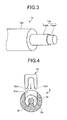
- FIG. 3 is a view schematically illustrating a structure of the optical fiber element wire 1a.
- the optical fiber 1aa is a so-called hard clad silica (HCS) optical fiber that is composed of a core portion 1aaa made of silica based glass and a cladding portion 1aab made of hard plastic having a lower refractive index than that of the core portion 1aaa and formed on the outer circumference of the core portion 1aaa.
- the core portion 1aaa has a core diameter of, for example, 200 ⁇ m
- the cladding portion 1aab has a clad diameter of, for example, 230 ⁇ m.
- the optical fiber 1aa is designed so as to transmit an optical signal of 850 nm at a low loss and over a wide bandwidth, to have a low bending loss, and to be strong against cyclic bending and pulling operations.
- the ferrule 2 has a cylindrical shape on the whole, and includes a front end portion 2a, a flange portion 2b provided along the outer circumference, a main body 2c, a base portion 2d, and the optical fiber fixing member 2e.
- the ferrule 2 is made of, for example, polyphenylene sulfide (PPS) resin excelling in thermal resistance, mechanical strength, and moldability.
- PPS polyphenylene sulfide
- the front end portion 2a has a front end face 2aa.
- the base portion 2d is located at an end on the opposite side of the front end face 2aa, and provided along the outer circumference thereof with projecting portions 2da, thus having a corrugated surface.
- a groove portion 2g is formed along the outer circumference between the main body 2c and the flange portion 2b.
- the ferrule 2 is also formed with an insertion hole 2h for inserting the end of the optical fiber cable 1 therein so that the insertion hole penetrates from the front end face 2aa to the base portion 2d.
- the diameter of the insertion hole 2h is set to substantially equal to or slightly larger than the outside diameter of the optical fiber 1aa at the front end portion 2a, and set to substantially equal to or slightly larger than the outside diameter of the optical fiber element wire 1a at other portions (except at an open hole 2ca to be described later).
- the optical fiber fixing member 2e has a gutter-like shape, and includes a groove 2ea for holding the optical fiber element wire 1a.
- the main body 2c of the ferrule 2 is formed on a side face thereof with the open hole 2ca for inserting the optical fiber fixing member 2e therein.
- the open hole 2ca has a shape that allows inner walls of the open hole 2ca to come contact with outer walls of the optical fiber fixing member 2e substantially without a space therebetween when the optical fiber fixing member 2e is inserted.
- the open hole 2ca is communicated with the insertion hole 2h, and is formed to a depth allowing a portion of the element wire coating portion 1ab of the optical fiber cable 1 inserted in the ferrule 2 to be exposed.
- a structure of the open hole 2ca of the ferrule 2 will be described later in detail.
- the optical fiber cable 1 is sequentially inserted through the protection boot 4 and the clinching ring 3.
- the outer coating portion 1c and the element wire coating portion 1ab at the end of the optical fiber cable 1 are partially removed to externally expose the optical fiber 1aa, the element wire coating portion 1ab, and the tensile member 1b by the respective predetermined lengths.
- the end of the optical fiber cable 1 is inserted from the side of the base portion 2d into the insertion hole 2h of the ferrule 2.
- the optical fiber cable 1 is inserted so that a front end face 1aac (refer to FIG. 1 ) of the optical fiber 1aa inserted in the insertion hole 2h is exposed to and is almost coplanar with the front end face 2aa of the ferrule 2.
- the element wire coating portion 1ab of the optical fiber element wire 1a results to be located in the position of the open hole 2ca.
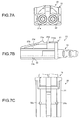
- FIG. 4 is a cross-sectional view in a plane perpendicular to the longitudinal direction of the ferrule 2 for explaining the state of inserting the optical fiber fixing member 2e into the ferrule 2.
- a support base 2i is provided on a bottom surface of the open hole 2ca of the ferrule 2 along the insertion direction of the optical fiber element wire 1a, and the optical fiber element wire 1a, when inserted, is supported by the support base 2i.
- the top of the support base 2i may be a plane surface, or a V-shaped or U-shaped groove for positioning the fiber element wire 1a.
- the optical fiber fixing member 2e is inserted into the open hole 2ca, and thus, the optical fiber element wire 1a is held by the groove 2ea.
- the groove 2ea is formed inside thereof with a corrugated portion 2eb. Therefore, when the optical fiber fixing member 2e holds the optical fiber element wire 1a with the groove 2ea, the frictional force increases between the groove 2ea and the optical fiber element wire 1a.
- the optical fiber fixing member 2e when inserted in the open hole 2ca, is pressed to be in contact with the ferrule 2 because the inner walls of the open hole 2ca are in contact with the outer walls of the optical fiber fixing member 2e substantially without a space therebetween, as described above.
- the optical fiber fixing member 2e fixes the optical fiber element wire 1a to the ferrule 2 with the frictional force and the pressure described above. As illustrated in FIG. 2 , a recess of the fixing member 2e and a projection provided in the open hole 2ca are fitted with each other, and thus, the fixing member 2e is prevented from coming off from the open hole 2ca.
- the attaching operation can be continued, for example, without waiting for adhesive to be solidified in the case of fixing the optical fiber element wire 1a with the adhesive.
- the time for the working process can be shortened.
- the fixing member 2e can be removed, and therefore, the relative positional relation between the ferrule 2 and the optical fiber element wire 1a can be easily adjusted.
- the inside diameter ⁇ 2h of the insertion hole 2h is 1.2 to 1.5 times as large as the outside diameter ⁇ 1a of the optical fiber element wire 1a, the optical fiber element wire 1a allowed to deflect in the fixing portion 2d (5 mm to 1.5 mm), and thus, in many cases, the optical fiber 1aa can be prevented from suffering damage by being pushed.
- the tensile member 1b is placed on the base portion 2d of the ferrule 2. At this time, it is preferable to place the tensile member 1b uniformly over the outer circumference of the base portion 2d. Then, the clinching ring 3 is fitted onto the base portion 2d, and the base portion 2d is clinched by the clinching ring 3 together with the tensile member 1b placed on the base portion 2d. Thereafter, the protection boot 4 is mounted on the clinching ring 3. Thus, the optical fiber terminals 10 are attached to the optical fiber cable 1 to produce the optical fiber cable with terminals.
- the protection boot 4 is made of, for example, rubber or elastic plastic, and prevents a joint portion between the optical fiber terminal 10 and the optical fiber cable 1 from bending to a smaller bending radius than an allowable radius, thereby preventing the optical fiber element wire 1a from breaking.
- the clinching ring 3 fixes the tensile member 1b to the ferrule 2, and thus, the tensile member 1b is fixed to the ferrule 2 to be integrated therewith. Therefore, a strong structure against vibration and impact is obtained.
- FIG. 5 is a partial cross-sectional view for explaining the state in which the tensile member 1b is fixed.
- the tensile member 1b is directly fixed to the base portion 2d of the ferrule 2 by the clinching ring 3.
- the optical fiber cable 1 and the optical fiber terminal 10 are integrated with each other at the joint portion therebetween, and thus are prevented from easily separating from each other even when the optical fiber cable 1 is pulled due to vibration or impact. Therefore, the optical fiber terminal 10 is strengthened against vibration and impact.
- the base portion 2d includes the projecting portions 2da along the outer circumference, and thus, the surface of the base portion 2d includes projections and recesses.
- a convex portion that is engaged with the groove of the base portion 2d may be provided on the inner circumference of the clinching ring 3.
- the optical fiber element wire 1a is fixed to the ferrule 2 using the optical fiber fixing member 2e. Accordingly, the optical fiber terminal 10 is further firmly connected with the optical fiber cable 1, and thus is further strengthened against vibration and impact. Moreover, this structure makes an external force applied to the optical fiber cable 1 act on the fixing portion, and thus, the end face side is hardly affected.
- the fixing portion is advantageous to have a length of 3 mm to 1.6 mm.
- the optical fiber terminal 10 according to the first embodiment hardly separates from the optical fiber cable 1 even when the optical fiber cable 1 is pulled due to vibration or impact.
- the optical fiber terminal 10 is strong against vibration and impact, and can endure a tensile force of, for example, as large as 100 N.
- Optical connectors according to the second and the third embodiments each includes the optical fiber terminal according to the first embodiment.
- FIG. 6 is a view schematically illustrating a state in which the optical connectors according to the second and the third embodiments are used.
- FIG. 6 illustrates an in-vehicle communication system 100.
- a control board 101 and a control board 102 provided in devices performing communication are connected to each other through optical fiber cables 103 and 104 with connectors, and perform mutual transmission of control signals.
- the control boards 101 and 102 are respectively equipped with fiber optical transceivers (FOTs) 101a and 102a, each of which includes a female connector structure.
- the optical fiber cable 103 with connectors is a cable in which male optical connectors 20 according to the second embodiment are attached to both ends of the optical fiber cable 1 illustrated in FIG. 2 .
- the optical fiber cable 104 with connectors is a cable in which the optical connector 20 and a female optical connector 30 according to the third embodiment are attached to the respective ends of the optical fiber cable 1.
- optical connectors 20 of the optical fiber cables 103 and 104 with connectors are connected to the FOTs 101a and 102a, respectively, while the other optical connector 20 of the optical fiber cable 103 with connectors is connected (that is, connected wire-to-wire) to the optical connector 30 of the optical fiber cable 104 with connectors. Accordingly, a signal transmission path is formed by the optical fiber cables 103 and 104 with connectors between the control boards 101 and 102, and thus, high-speed and large-capacity communication is enabled.
- FIGS. 7A, 7B, and 7C are front, side, and plan views, respectively, schematically illustrating the optical fiber cable with connectors in which the optical connector according to the second embodiment is attached to the end of the optical fiber cable.
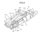
- FIG. 8 is a partial cross-sectional view of the optical connector illustrated in FIGS. 7A to 7C .
- the optical connector 20 includes the optical fiber terminals 10 according to the first embodiment, a housing 21 for holding the optical fiber terminals 10, and an optical fiber terminal fixing member 22 for fixing the optical fiber terminals 10 to the housing 21.
- the housing 21 includes two insertion holes 21a formed in parallel with each other in the longitudinal direction for inserting therein the two optical fiber terminals 10 attached to the respective ends of the duplex optical fiber cable 1; a slit 21b formed so as to penetrate from a top surface to a bottom surface of the housing 21 and so as to communicate with the insertion holes 21a in order to insert therein the optical fiber terminal fixing member 22; an elastic arm portion 21c formed so as to slant obliquely upward from the front end to the rear end in the longitudinal direction in the substantially middle in the width direction; a hook portion 21d for hooking and stopping a front end portion 21ca of the arm portion 21c; and a latch projection 21e formed on an upper portion of the arm portion 21c.
- the housing 21 is made of, for example, PPS or polybutylene terephthalate (PBT). Considering the use in a car, a resin that is thermally resistant and has low thermal expansion rate is suitable.
- FIGS. 9A and 9B are front and side views, respectively, schematically illustrating a structure of the optical fiber terminal fixing member illustrated in FIGS. 7A to 7C .
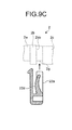
- FIG. 9C is a view illustrating a cross section taken along line A-A in FIG. 9A and a state in which the optical fiber terminal fixing member fixes the optical fiber terminal.
- the optical fiber terminal fixing member 22 includes a main body 22a, fitting portions 22b formed so as to project from both ends in the width direction of the main body 22a, a latch portion 22c formed so as to project from the substantially middle in the width direction of the main body 22a, and a spring portion 22d. Two gaps 22e are formed between the fitting portions 22b and both the latch portion 22c and the spring portion 22d.
- the optical fiber terminal fixing member 22 is made of, for example, PPS or PBT.
- the thickness of the fitting portions 22b is set to substantially equal to or slightly smaller than the width of the groove portion 2g of the ferrule 2.
- the latch portion 22c is provided slightly on the front side of the fitting portions 22b, and provided at a front end thereof with a latching pawl 22ca. As illustrated in FIGS. 9B and 9C , when viewed from the side, the spring portion 22d is curved in a circular arc shape so as to project toward the latch portion 22c, and formed so that the arc-shaped portion projects higher than the surface of the fitting portion 22b on the side of the latch portion 22c.
- the two optical fiber terminals 10 are inserted into the insertion holes 21a of the housing 21 so that the front end faces 2ba of the flange portions 2b of the ferrules 2 abut against the restricting surfaces 21f in the insertion holes 21a.
- the groove portions 2g of the ferrules 2 are located so as to overlap with the slit 21b formed in the housing 21.
- the optical fiber terminal fixing member 22 is inserted from the bottom side of the housing 21 into the slit 21b.
- the two fitting portions 22b of the optical fiber terminal fixing member 22 are inserted into the two respective outside groove portions 2g of the two ferrules 2.
- the front ends of the fitting portions 22b reach the slit 21b in the top surface and are inserted therein. Accordingly, the optical fiber terminal fixing member 22 is restricted from moving in the longitudinal direction by the slit 21b in the top and bottom surfaces.
- the spring portion 22d is inserted into each of the two groove portions 2g of the ferrules 2 in the state in which the curved portion is pressed backward by the flange portion 2b.
- the spring portion 22d presses a rear end face 2bb of the flange portion 2b, and thus, the front end face 2ba of the flange portion 2b is pressed by the restricting surface 21f of the housing 21 toward the front end face 2aa of the ferrule 2.
- the ferrule 2 is pressed and stopped by the restricting surface 21f of the housing 21.
- the latch portion 22c passes between the two ferrules 2, and the latching pawl 22ca is engaged into the slit 21b in the top surface of the housing 21. Accordingly, the optical fiber terminal fixing member 22 is fixed to the housing 21.
- the two ferrules 2 are disposed in the two gaps 22e.
- the fitting portions 22b of the optical fiber terminal fixing member 22 fit in the groove portions 2g of the ferrules 2, and the optical fiber terminal fixing member 22 also fits in the slit 21b. Accordingly, the optical fiber terminals 10 are firmly fixed to the housing 21, and thus, the optical connector 20 is further strengthened against vibration and impact. Therefore, the optical connector 20 can endure a tensile force of, for example, as large as 100 N, and has high connection reliability.
- the optical fiber terminal fixing member 22 uses the spring portion 22d to press the optical fiber terminal 10 to be stopped against the restricting surface 21f of the housing 21, and thus, the optical fiber terminal 10 is further restricted from moving toward the front end face thereof. Accordingly, the front end face 2aa of the optical fiber terminal 10 can be set in a desired position.
- FIGS. 10A, 10B, and 10C are front, side, and plan views, respectively, schematically illustrating the optical fiber cable with connectors in which the optical connector according to the third embodiment is attached to the end of the optical fiber cable.
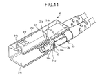
- FIG. 11 is a partial cross-sectional view of the optical connector illustrated in FIGS. 10A to 10C .
- the optical connector 30 includes the optical fiber terminals 10 according to the first embodiment, a housing 31 for holding the optical fiber terminals 10, and the optical fiber terminal fixing member 22 similar to those in FIGS. 9A to 9C for fixing the optical fiber terminals 10 to the housing 31.
- the housing 31 includes two insertion holes 31a formed in parallel with each other in the longitudinal direction for inserting therein the two optical fiber terminals 10 attached to the respective ends of the duplex optical fiber cable 1; a slit 31b formed so as to penetrate from a bottom surface to a top surface of the housing 31 and so as to communicate with the insertion holes 31a in order to insert therein the optical fiber terminal fixing member 22; and a receptacle 31c that communicates toward the front end thereof from the insertion holes 31a to house the optical connector 20 according to the second embodiment inserted therein.
- the top surface of the housing 31 is formed with a projection 31d.
- the projection 31d is formed inside thereof with a guide groove 31e, in a continuous manner with the receptacle 31c, through which the arm portion 21c is guided when the optical connector 20 is inserted.
- the projection 31d is formed with a latch hole 31f serving as a fixing structure for receiving the latch projection 21e fitted therein.
- An inner wall of the insertion hole 31a is provided with a restricting surface 31g that abuts against the front end face 2ba of the flange portion 2b of the optical fiber terminal 10 to restrict the optical fiber terminal 10 from moving forward.
- the housing 31 is made of, for example, PPS or PBT.
- the two optical fiber terminals 10 are inserted into the insertion holes 31a of the housing 31 so that the front end faces 2ba of the flange portions 2b of the ferrules 2 abut against the restricting surfaces 31g in the insertion holes 31a.
- the groove portions 2g of the ferrules 2 are located so as to overlap with the slit 31b formed in the housing 31.
- the optical fiber terminal fixing member 22 is inserted from the top of the housing 31 into the slit 31b.
- the two fitting portions 22b of the optical fiber terminal fixing member 22 are inserted into the two respective outside groove portions 2g of the two ferrules 2.
- the front ends of the fitting portions 22b reach the slit 21b on the bottom surface side and are inserted therein. Accordingly, the optical fiber terminal fixing member 22 is restricted from moving in the longitudinal direction by the slit 31b in the top and bottom surfaces.
- the spring portion 22d is inserted into each of the two groove portions 2g of the ferrules 2 in the state in which the curved portion is pressed backward by the flange portion 2b.
- the spring portion 22d presses the rear end face 2bb of the flange portion 2b, and thus, the front end face 2ba of the flange portion 2b is pressed by the restricting surface 31g of the housing 31 toward the front end face 2aa of the ferrule 2.
- the ferrule 2 is pressed and stopped by the restricting surface 31g of the housing 31.
- the latch portion 22c passes between the two ferrules 2, and the latching pawl 22ca is engaged into the slit 31b in the bottom surface of the housing 31. Accordingly, the optical fiber terminal fixing member 22 is fixed to the housing 31.
- the two ferrules 2 are disposed in the two respective gaps 22e.
- the fitting portions 22b of the optical fiber terminal fixing member 22 fit in the groove portions 2g of the ferrules 2, and the optical fiber terminal fixing member 22 also fits in the slit 31b. Accordingly, the optical fiber terminals 10 are firmly fixed to the housing 31, and thus, the optical connector 30 is further strengthened against vibration and impact. Therefore, the optical connector 30 can endure a tensile force of, for example, as large as 100 N, and has high connection reliability.
- the optical fiber terminal fixing member 22 uses the spring portion 22d to press the optical fiber terminal 10 to be stopped against the restricting surface 31g of the housing 31, and thus, the optical fiber terminal 10 is further restricted from moving toward the front end face thereof. Accordingly, the front end face 2aa of the optical fiber terminal 10 can be set in a desired position.
- FIG. 12 is a partial cross-sectional view illustrating a state in which the optical connector 20 according to the second embodiment illustrated in FIGS. 7A to 7C is connected with the optical connector 30 according to the third embodiment illustrated in FIGS. 10A to 10C .
- the optical connector 20 is inserted into the receptacle 31c of the optical connector 30.
- the arm portion 21c of the optical connector 20 is guided by the guide groove 31e, and the latch projection 21e fits into the latch hole 31f and is engaged therein.
- the optical connector 20 is connected with the optical connector 30.
- the connection is to be released, the front end portion 21ca of the arm portion 21c of the optical connector 20 is pressed down, and the latch projection 21e and the latch hole 31f are disengaged from each other.
- the connection can be released.
- a gap G having a predetermined width is formed between the front end faces 2aa of the optical fiber terminals 10 opposed to each other. Because the gap G is formed in this manner, the front end faces 1aac of the optical fibers 1aa lying in the same planes as the corresponding front end faces 2aa of the optical fiber terminals 10 do not rub each other even if, for example, the optical fiber terminals 10 are shaken due to vibration or impact, or the optical connector 20 and the optical connector 30 are repeatedly mounted and dismounted in the production and maintenance processes or the like. Therefore, the front end face 1aac is prevented from being broken or flawed.
- the width of the gap G is set to, for example, 500 ⁇ m or less, and preferably 30 ⁇ m to 300 ⁇ m, and is set so that the optical fiber cables 1 are connected to each other at a low optical loss depending on the core diameter and the numerical aperture of the optical fiber 1aa, pistoning of the optical fiber 1aa, and the like.
- the optical fiber terminal 10 is ensured to be restricted from moving toward the front end thereof by the optical fiber terminal fixing member 22 and by the flange portion 2b and the restricting surface 21f or 31g of the optical fiber terminal 10, and moreover, the optical fiber terminal 10 is formed in an integral manner so that the ferrule 2 and the optical fiber 1aa are not displaced relative to each other.
- the gap G is maintained even when vibration or impact is applied to the optical connectors 20 and 30 connected to each other. Therefore, the front end faces 2aa of the optical fiber terminals 10 do not come in contact with each other, and thus, the front end face 1aac of the optical fiber 1aa is prevented from being broken or flawed.
- the optical fiber cable can use wire-like tensile member made of, for example, metal or FRP.
- the optical fiber fixing member to fix the optical fiber to the ferrule
- the optical fiber can be bonded to be fixed to the ferrule.
- the present invention is not limited thereto but can also be applied to a simplex optical fiber cable or a multiplex optical fiber cable including three or more cables.
- the present invention is not limited by the above-described embodiments.
- the present invention also includes structures obtained by appropriately combining the component parts described above. Further effects and variations can be easily derived by those skilled in the art. Therefore, wider aspects of the present invention are not limited to the above described embodiments, and various modifications are possible.
- the optical fiber terminal, the optical fiber cable with the terminal, the optical connector, the optical fiber cable with the connector, and the connecting structure according to the present invention are preferably used mainly for applications in information communication in a vehicle.
Landscapes
- Physics & Mathematics (AREA)
- General Physics & Mathematics (AREA)
- Optics & Photonics (AREA)
- Mechanical Coupling Of Light Guides (AREA)
Abstract
An optical fiber terminal is configured to be attached to an end of an optical fiber cable. The optical fiber cable includes an optical fiber element wire having an optical fiber covered by an element wire coating, a tensile member disposed along a longitudinal direction of the optical fiber element wire, and a coating portion that covers the optical fiber element wire and the tensile member. The optical fiber terminal includes a ferrule and a tensile member fixing member for fixing the tensile member to the ferrule. The ferrule has an insertion hole for inserting and fixing the optical fiber element wire, and a front end face on which a front end face of the optical fiber inserted in the insertion hole is configured to be exposed. There is thus provided an optical fiber terminal which can achieve an optical connector that is strong against vibration and impact, an optical fiber cable with the terminal, the optical connector, an optical fiber cable with the connector, and a connection structure.
Description
- The present invention relates to an optical fiber terminal, an optical fiber cable with a terminal, an optical connector, an optical fiber cable with a connector, and a connection structure.
- Along with an increase in the amount of communication of information in a vehicle, such as control signals, image signals, and audio signals, in recent years, transmission paths used for transmission of the information signals have begun using optical fiber cables instead of conventional metal cables (refer to
Patent Literatures 1 and 2). Unlike the metal cable, the optical fiber cable is free from a problem of emitting noise therearound due to increase in the communication speed, and thus is a signal transmission path suitable for high-speed and large-capacity information communication. - The optical fiber cable is provided at an end thereof with an optical connector. The optical connector includes a terminal (optical fiber terminal) including a ferrule and the like to be attached to the end of the optical fiber cable, and a housing having a structure for being connected to another optical connector or the like. On the other hand, an optical connector is also provided on a device performing communication, and the optical fiber cable can be connected with the device performing communication by connecting the optical connectors to each other. The optical connectors also achieve a connection between optical fiber cables. The connection between optical fiber cables is called wire-to-wire connection.
-
- Patent Literature 1: Japanese Patent Application Laid-open No.
2002-107573 - Patent Literature 2: Japanese Patent No.
3813496 - When optical fiber cables are applied to wire harnesses in a vehicle, a device performing communication through the wire harnesses is disposed at each component unit of the vehicle, such as a roof portion, a floor portion, an engine and surroundings thereof, and an instrument panel and surroundings thereof. Therefore, among components in the wire harnesses connecting between the communication devices disposed at the respective component units, particularly the optical connector used for the wire-to-wire connection can be repeatedly mounted and dismounted many times, for example, in the assembly process and the mounting process during the vehicle production, and in the inspection and maintenance, and thus can be subjected to strong impacts such as tensions at those occasions. The optical connector is also subjected to vibration, impacts, and the like while the vehicle is running. Accordingly, particularly the optical connectors used in a vehicle are particularly required to be strong against vibration and impact.
- The present invention has been made in view of the description above, and it is an object of the present invention to provide an optical fiber terminal which can achieve an optical connector that is strong against vibration and impact, an optical fiber cable with the terminal, the optical connector, an optical fiber cable with the connector, and a connection structure.
- In order to solve the problems and to attain the object, an optical fiber terminal according to the present invention is configured to be attached to an end of an optical fiber cable. The optical fiber cable includes: an optical fiber element wire having an optical fiber covered by an element wire coating; a tensile member disposed along a longitudinal direction of the optical fiber element wire; and a coating portion that covers the optical fiber element wire and the tensile member. The optical fiber terminal includes: a ferrule that has an insertion hole for inserting and fixing the optical fiber element wire, and a front end face on which a front end face of the optical fiber inserted in the insertion hole is configured to be exposed; and a tensile member fixing member for fixing the tensile member to the ferrule.
- In the above invention, according to the optical fiber terminal of the present invention, the tensile member is made of resin fibers; the ferrule includes a base portion for placing thereon the tensile member at an opposite end to the front end face of the ferrule; and the tensile member fixing member is a clinching member configured to be fitted into the base portion of the ferrule to clinch the base portion of the ferrule together with the tensile member placed on the base portion.
- In the above invention, according to the optical fiber terminal of the present invention, the ferrule includes an optical fiber fixing member having a groove for holding the optical fiber element wire, and an open hole formed on a side face of the ferrule, the open hole having a depth at which the inserted optical fiber element wire is at least exposed. The optical fiber fixing member is configured to be inserted into the open hole of the ferrule, and the inserted optical fiber element wire is configured to be held by the groove to fix the inserted optical fiber element wire.
- An optical fiber cable with a terminal according to the present invention includes: an optical fiber cable including an optical fiber element wire having an optical fiber covered by an element wire coating, a tensile member disposed along a longitudinal direction of the optical fiber element wire, and a coating portion that covers the optical fiber element wire and the tensile member; and the optical fiber terminal according to any one of the above inventions that is attached to an end of the optical fiber cable.
- An optical connector according to the present invention includes: the optical fiber terminal according to any one of the above inventions; and a housing that holds the optical fiber terminal. The housing includes a fixing structure for fixing the optical connector to another optical connector in a removable manner.
- In the above invention, according to the optical connector of the present invention, the fixing structure is a latch structure for engaging the optical connector with another optical connector.
- In the above invention, the optical connector of the present invention further includes an optical fiber terminal fixing member for fixing the optical fiber terminal to the housing. The ferrule includes a groove on an outer circumference of the ferrule, and the optical fiber terminal fixing member is configured to be fitted into the groove.
- In the above invention, according to the optical connector of the present invention, the housing includes a restricting surface for restricting the optical fiber terminal from moving toward the front end face of the ferrule.
- In the above invention, according to the optical connector of the present invention, the ferrule includes a flange portion that abuts against the restricting surface of the housing to restrict the optical fiber terminal from moving toward the front end face of the ferrule.
- An optical fiber cable with a connector according to the present invention includes: an optical fiber cable including an optical fiber element wire having an optical fiber covered by an element wire coating, a tensile member disposed along a longitudinal direction of the optical fiber element wire, and a coating portion that covers the optical fiber element wire and the tensile member; and the optical connector according to any one of the above inventions that is attached to an end of the optical fiber cable.
- A connection structure of an optical connector according to the present invention includes at least two ferrules, into each of which an optical fiber is incorporated, the ferrules being arranged in a longitudinal direction in a manner opposed to each other. The connection structure restricts the ferrules from moving in directions coming close to each other and maintains a shortest distance between connection end faces of the at least two ferrules at 30 µm to 300 µm.
- According to the present invention, because a tensile member is directly fixed to a ferrule so as to be integrated therewith, an optical connector that is strong against vibration and impact can be achieved.
-
-
FIG. 1 is a view schematically illustrating an optical fiber cable with terminals in which optical fiber terminals according to a first embodiment are attached to an end of the optical fiber cable. -
FIG. 2 is a schematic exploded view of the optical fiber cable with terminals illustrated inFIG. 1 . -
FIG. 3 is a view schematically illustrating a structure of an optical fiber element wire. -
FIG. 4 is a cross-sectional view for explaining a state of inserting an optical fiber fixing member into a ferrule. -
FIG. 5 is a partial cross-sectional view for explaining a state in which a tensile member is fixed. -
FIG. 6 is a view schematically illustrating a state in which optical connectors according to a second embodiment and a third embodiment are used. -
FIG. 7A is a front view schematically illustrating an optical fiber cable with connectors in which the optical connector according to the second embodiment is attached to an end of the optical fiber cable. -
FIG. 7B is a side view schematically illustrating the optical fiber cable with connectors in which the optical connector according to the second embodiment is attached to the end of the optical fiber cable. -
FIG. 7C is a plan view schematically illustrating the optical fiber cable with connectors in which the optical connector according to the second embodiment is attached to the end of the optical fiber cable. -
FIG. 8 is a partial cross-sectional view of the optical connector illustrated inFIGS. 7A to 7C . -
FIG. 9A is a front view schematically illustrating a structure of an optical fiber terminal fixing member illustrated inFIGS. 7A to 7C . -
FIG. 9B is a side view schematically illustrating the structure of the optical fiber terminal fixing member illustrated inFIGS. 7A to 7C . -
FIG. 9C is a view illustrating a cross section taken along line A-A inFIG. 9A and a state in which the optical fiber terminal fixing member fixes the optical fiber terminal. -
FIG. 10A is a front view schematically illustrating an optical fiber cable with connectors in which the optical connector according to the third embodiment is attached to an end of the optical fiber cable. -
FIG. 10B is a side view schematically illustrating the optical fiber cable with connectors in which the optical connector according to the third embodiment is attached to the end of the optical fiber cable. -
FIG. 10C is a plan view schematically illustrating the optical fiber cable with connectors in which the optical connector according to the third embodiment is attached to the end of the optical fiber cable. -
FIG. 11 is a partial cross-sectional view of the optical connector illustrated inFIGS. 10A to 10C . -
FIG. 12 is a partial cross-sectional view illustrating a state in which the optical connector illustrated inFIGS. 7A to 7C is connected with the optical connector illustrated inFIGS. 10A to 10C . - A description will be made below in detail of embodiments of an optical fiber terminal, an optical fiber cable with terminals, optical connectors, an optical fiber cable with connectors, and a connection structure according to the present invention with reference to the accompanying drawings. Note that the present invention is not limited by the embodiments.
- First, an optical fiber terminal according to a first embodiment of the present invention will be described.
FIG. 1 is a view schematically illustrating an optical fiber cable with terminals in which the optical fiber terminals according to the first embodiment are attached to an end of the optical fiber cable. As illustrated inFIG. 1 ,optical fiber terminals 10 are attached to respective pieces of the end of anoptical fiber cable 1 to be attached to a duplex optical connector, and provided each with aferrule 2, a clinchingring 3 serving as a fixing member for a tensile member, and aprotection boot 4. Theferrule 2 includes an opticalfiber fixing member 2e. The twooptical fiber terminals 10 have the same structure as each other, and therefore, one of theoptical fiber terminals 10 will be described below. -
FIG. 2 is a schematic exploded view of the optical fiber cable with terminals illustrated inFIG. 1 . As illustrated inFIG. 2 , theoptical fiber cable 1 includes an opticalfiber element wire 1a composed of an optical fiber 1aa and an element wire coating portion 1ab that is formed along the longitudinal direction of the outer circumference of the optical fiber 1aa to clad the optical fiber 1aa. Theoptical fiber cable 1 also includes atensile member 1b disposed along the longitudinal direction of the outer circumference of the opticalfiber element wire 1a, and further includes anouter coating portion 1c covering the outer circumference of thetensile member 1b along the longitudinal direction. Thetensile member 1b is made of aramid resin fibers such as Kevlar (registered trademark), and are disposed so as to surround the outer circumference of the opticalfiber element wire 1a. The element wire coating portion 1ab is made of, for example, polyamide resin. The element wire coating portion 1ab and theouter coating portion 1c are partially removed at the end of theoptical fiber cable 1, and thus, the optical fiber 1aa, the element wire coating portion 1ab, and thetensile member 1b are externally exposed by respective predetermined lengths. -
FIG. 3 is a view schematically illustrating a structure of the opticalfiber element wire 1a. As illustrated inFIG. 3 , the optical fiber 1aa is a so-called hard clad silica (HCS) optical fiber that is composed of a core portion 1aaa made of silica based glass and a cladding portion 1aab made of hard plastic having a lower refractive index than that of the core portion 1aaa and formed on the outer circumference of the core portion 1aaa. The core portion 1aaa has a core diameter of, for example, 200 µm, and the cladding portion 1aab has a clad diameter of, for example, 230 µm. The optical fiber 1aa is designed so as to transmit an optical signal of 850 nm at a low loss and over a wide bandwidth, to have a low bending loss, and to be strong against cyclic bending and pulling operations. - Referring back to
FIG. 2 , theferrule 2 has a cylindrical shape on the whole, and includes afront end portion 2a, aflange portion 2b provided along the outer circumference, amain body 2c, abase portion 2d, and the opticalfiber fixing member 2e. Theferrule 2 is made of, for example, polyphenylene sulfide (PPS) resin excelling in thermal resistance, mechanical strength, and moldability. Thefront end portion 2a has a front end face 2aa. Thebase portion 2d is located at an end on the opposite side of the front end face 2aa, and provided along the outer circumference thereof with projecting portions 2da, thus having a corrugated surface. Agroove portion 2g is formed along the outer circumference between themain body 2c and theflange portion 2b. Theferrule 2 is also formed with aninsertion hole 2h for inserting the end of theoptical fiber cable 1 therein so that the insertion hole penetrates from the front end face 2aa to thebase portion 2d. The diameter of theinsertion hole 2h is set to substantially equal to or slightly larger than the outside diameter of the optical fiber 1aa at thefront end portion 2a, and set to substantially equal to or slightly larger than the outside diameter of the opticalfiber element wire 1a at other portions (except at an open hole 2ca to be described later). - The optical
fiber fixing member 2e has a gutter-like shape, and includes a groove 2ea for holding the opticalfiber element wire 1a. Themain body 2c of theferrule 2 is formed on a side face thereof with the open hole 2ca for inserting the opticalfiber fixing member 2e therein. The open hole 2ca has a shape that allows inner walls of the open hole 2ca to come contact with outer walls of the opticalfiber fixing member 2e substantially without a space therebetween when the opticalfiber fixing member 2e is inserted. In addition, the open hole 2ca is communicated with theinsertion hole 2h, and is formed to a depth allowing a portion of the element wire coating portion 1ab of theoptical fiber cable 1 inserted in theferrule 2 to be exposed. A structure of the open hole 2ca of theferrule 2 will be described later in detail. - A description will be made next of a method for attaching the
optical fiber terminal 10 to the end of theoptical fiber cable 1. First, theoptical fiber cable 1 is sequentially inserted through theprotection boot 4 and the clinchingring 3. Next, theouter coating portion 1c and the element wire coating portion 1ab at the end of theoptical fiber cable 1 are partially removed to externally expose the optical fiber 1aa, the element wire coating portion 1ab, and thetensile member 1b by the respective predetermined lengths. - Then, the end of the
optical fiber cable 1 is inserted from the side of thebase portion 2d into theinsertion hole 2h of theferrule 2. At this time, theoptical fiber cable 1 is inserted so that a front end face 1aac (refer toFIG. 1 ) of the optical fiber 1aa inserted in theinsertion hole 2h is exposed to and is almost coplanar with the front end face 2aa of theferrule 2. Then, the element wire coating portion 1ab of the opticalfiber element wire 1a results to be located in the position of the open hole 2ca. - Next, the optical
fiber fixing member 2e is inserted into the open hole 2ca so as to hold the opticalfiber element wire 1a and thus to fix the opticalfiber element wire 1a to theferrule 2.FIG. 4 is a cross-sectional view in a plane perpendicular to the longitudinal direction of theferrule 2 for explaining the state of inserting the opticalfiber fixing member 2e into theferrule 2. As illustrated inFIG. 4 , asupport base 2i is provided on a bottom surface of the open hole 2ca of theferrule 2 along the insertion direction of the opticalfiber element wire 1a, and the opticalfiber element wire 1a, when inserted, is supported by thesupport base 2i. The top of thesupport base 2i may be a plane surface, or a V-shaped or U-shaped groove for positioning thefiber element wire 1a. - The optical
fiber fixing member 2e is inserted into the open hole 2ca, and thus, the opticalfiber element wire 1a is held by the groove 2ea. The groove 2ea is formed inside thereof with a corrugated portion 2eb. Therefore, when the opticalfiber fixing member 2e holds the opticalfiber element wire 1a with the groove 2ea, the frictional force increases between the groove 2ea and the opticalfiber element wire 1a. In addition, the opticalfiber fixing member 2e, when inserted in the open hole 2ca, is pressed to be in contact with theferrule 2 because the inner walls of the open hole 2ca are in contact with the outer walls of the opticalfiber fixing member 2e substantially without a space therebetween, as described above. The opticalfiber fixing member 2e fixes the opticalfiber element wire 1a to theferrule 2 with the frictional force and the pressure described above. As illustrated inFIG. 2 , a recess of the fixingmember 2e and a projection provided in the open hole 2ca are fitted with each other, and thus, the fixingmember 2e is prevented from coming off from the open hole 2ca. By fixing the opticalfiber element wire 1a to theferrule 2 using the opticalfiber fixing member 2e such as described above, the attaching operation can be continued, for example, without waiting for adhesive to be solidified in the case of fixing the opticalfiber element wire 1a with the adhesive. Thus, the time for the working process can be shortened. The fixingmember 2e can be removed, and therefore, the relative positional relation between theferrule 2 and the opticalfiber element wire 1a can be easily adjusted. By setting the inside diameter ϕ2h of theinsertion hole 2h to be 1.2 to 1.5 times as large as the outside diameter ϕ1a of the opticalfiber element wire 1a, the opticalfiber element wire 1a allowed to deflect in the fixingportion 2d (5 mm to 1.5 mm), and thus, in many cases, the optical fiber 1aa can be prevented from suffering damage by being pushed. - Next, the
tensile member 1b is placed on thebase portion 2d of theferrule 2. At this time, it is preferable to place thetensile member 1b uniformly over the outer circumference of thebase portion 2d. Then, the clinchingring 3 is fitted onto thebase portion 2d, and thebase portion 2d is clinched by the clinchingring 3 together with thetensile member 1b placed on thebase portion 2d. Thereafter, theprotection boot 4 is mounted on the clinchingring 3. Thus, theoptical fiber terminals 10 are attached to theoptical fiber cable 1 to produce the optical fiber cable with terminals. Theprotection boot 4 is made of, for example, rubber or elastic plastic, and prevents a joint portion between theoptical fiber terminal 10 and theoptical fiber cable 1 from bending to a smaller bending radius than an allowable radius, thereby preventing the opticalfiber element wire 1a from breaking. - Here, in the
optical fiber terminal 10, the clinchingring 3 fixes thetensile member 1b to theferrule 2, and thus, thetensile member 1b is fixed to theferrule 2 to be integrated therewith. Therefore, a strong structure against vibration and impact is obtained. -
FIG. 5 is a partial cross-sectional view for explaining the state in which thetensile member 1b is fixed. As illustrated inFIG. 5 , thetensile member 1b is directly fixed to thebase portion 2d of theferrule 2 by the clinchingring 3. For this reason, theoptical fiber cable 1 and theoptical fiber terminal 10 are integrated with each other at the joint portion therebetween, and thus are prevented from easily separating from each other even when theoptical fiber cable 1 is pulled due to vibration or impact. Therefore, theoptical fiber terminal 10 is strengthened against vibration and impact. Thebase portion 2d includes the projecting portions 2da along the outer circumference, and thus, the surface of thebase portion 2d includes projections and recesses. Consequently, after being clinched by the clinchingring 3, thetensile member 1b, when pulled, is caught on the projecting portions 2da to be prevented from being easily pulled out, and thus is further strengthened against tension. A convex portion that is engaged with the groove of thebase portion 2d may be provided on the inner circumference of the clinchingring 3. - In addition, in the
optical fiber terminal 10, the opticalfiber element wire 1a is fixed to theferrule 2 using the opticalfiber fixing member 2e. Accordingly, theoptical fiber terminal 10 is further firmly connected with theoptical fiber cable 1, and thus is further strengthened against vibration and impact. Moreover, this structure makes an external force applied to theoptical fiber cable 1 act on the fixing portion, and thus, the end face side is hardly affected. For this purpose, the fixing portion is advantageous to have a length of 3 mm to 1.6 mm. - As has been described above, the
optical fiber terminal 10 according to the first embodiment hardly separates from theoptical fiber cable 1 even when theoptical fiber cable 1 is pulled due to vibration or impact. Thus, theoptical fiber terminal 10 is strong against vibration and impact, and can endure a tensile force of, for example, as large as 100 N. - Next, a second embodiment and a third embodiment will be described. Optical connectors according to the second and the third embodiments each includes the optical fiber terminal according to the first embodiment.
-
FIG. 6 is a view schematically illustrating a state in which the optical connectors according to the second and the third embodiments are used.FIG. 6 illustrates an in-vehicle communication system 100. In this in-vehicle communication system 100, acontrol board 101 and acontrol board 102 provided in devices performing communication are connected to each other throughoptical fiber cables - The
control boards optical fiber cable 103 with connectors is a cable in which maleoptical connectors 20 according to the second embodiment are attached to both ends of theoptical fiber cable 1 illustrated inFIG. 2 . Theoptical fiber cable 104 with connectors is a cable in which theoptical connector 20 and a femaleoptical connector 30 according to the third embodiment are attached to the respective ends of theoptical fiber cable 1. Theoptical connectors 20 of theoptical fiber cables FOTs optical connector 20 of theoptical fiber cable 103 with connectors is connected (that is, connected wire-to-wire) to theoptical connector 30 of theoptical fiber cable 104 with connectors. Accordingly, a signal transmission path is formed by theoptical fiber cables control boards - Next, the optical connector according to the second embodiment will be specifically described.
FIGS. 7A, 7B, and 7C are front, side, and plan views, respectively, schematically illustrating the optical fiber cable with connectors in which the optical connector according to the second embodiment is attached to the end of the optical fiber cable.FIG. 8 is a partial cross-sectional view of the optical connector illustrated inFIGS. 7A to 7C . - As illustrated in
FIGS. 7A to 7c and8 , theoptical connector 20 includes theoptical fiber terminals 10 according to the first embodiment, ahousing 21 for holding theoptical fiber terminals 10, and an optical fiberterminal fixing member 22 for fixing theoptical fiber terminals 10 to thehousing 21. - The
housing 21 includes twoinsertion holes 21a formed in parallel with each other in the longitudinal direction for inserting therein the twooptical fiber terminals 10 attached to the respective ends of the duplexoptical fiber cable 1; aslit 21b formed so as to penetrate from a top surface to a bottom surface of thehousing 21 and so as to communicate with theinsertion holes 21a in order to insert therein the optical fiberterminal fixing member 22; anelastic arm portion 21c formed so as to slant obliquely upward from the front end to the rear end in the longitudinal direction in the substantially middle in the width direction; ahook portion 21d for hooking and stopping a front end portion 21ca of thearm portion 21c; and alatch projection 21e formed on an upper portion of thearm portion 21c. An inner wall of theinsertion hole 21a is provided with a restrictingsurface 21f that abuts against a front end face 2ba of theflange portion 2b of theoptical fiber terminal 10 to restrict theoptical fiber terminal 10 from moving toward the side of the front end face thereof. Thehousing 21 is made of, for example, PPS or polybutylene terephthalate (PBT). Considering the use in a car, a resin that is thermally resistant and has low thermal expansion rate is suitable. -
FIGS. 9A and 9B are front and side views, respectively, schematically illustrating a structure of the optical fiber terminal fixing member illustrated inFIGS. 7A to 7C .FIG. 9C is a view illustrating a cross section taken along line A-A inFIG. 9A and a state in which the optical fiber terminal fixing member fixes the optical fiber terminal. As illustrated inFIGS. 9A to 9C , the optical fiberterminal fixing member 22 includes amain body 22a,fitting portions 22b formed so as to project from both ends in the width direction of themain body 22a, alatch portion 22c formed so as to project from the substantially middle in the width direction of themain body 22a, and aspring portion 22d. Twogaps 22e are formed between thefitting portions 22b and both thelatch portion 22c and thespring portion 22d. The optical fiberterminal fixing member 22 is made of, for example, PPS or PBT. - The thickness of the
fitting portions 22b is set to substantially equal to or slightly smaller than the width of thegroove portion 2g of theferrule 2. Thelatch portion 22c is provided slightly on the front side of thefitting portions 22b, and provided at a front end thereof with a latching pawl 22ca. As illustrated inFIGS. 9B and9C , when viewed from the side, thespring portion 22d is curved in a circular arc shape so as to project toward thelatch portion 22c, and formed so that the arc-shaped portion projects higher than the surface of thefitting portion 22b on the side of thelatch portion 22c. - Next, a method for assembling the
optical connector 20 will be described. First, as illustrated inFIG. 8 , the twooptical fiber terminals 10 are inserted into theinsertion holes 21a of thehousing 21 so that the front end faces 2ba of theflange portions 2b of theferrules 2 abut against the restrictingsurfaces 21f in theinsertion holes 21a. At this time, thegroove portions 2g of theferrules 2 are located so as to overlap with theslit 21b formed in thehousing 21. - Then, the optical fiber
terminal fixing member 22 is inserted from the bottom side of thehousing 21 into theslit 21b. As a result, as illustrated inFIG. 9C , the twofitting portions 22b of the optical fiberterminal fixing member 22 are inserted into the two respectiveoutside groove portions 2g of the twoferrules 2. The front ends of thefitting portions 22b reach theslit 21b in the top surface and are inserted therein. Accordingly, the optical fiberterminal fixing member 22 is restricted from moving in the longitudinal direction by theslit 21b in the top and bottom surfaces. - The
spring portion 22d is inserted into each of the twogroove portions 2g of theferrules 2 in the state in which the curved portion is pressed backward by theflange portion 2b. As a result, thespring portion 22d presses a rear end face 2bb of theflange portion 2b, and thus, the front end face 2ba of theflange portion 2b is pressed by the restrictingsurface 21f of thehousing 21 toward the front end face 2aa of theferrule 2. Accordingly, theferrule 2 is pressed and stopped by the restrictingsurface 21f of thehousing 21. Thelatch portion 22c passes between the twoferrules 2, and the latching pawl 22ca is engaged into theslit 21b in the top surface of thehousing 21. Accordingly, the optical fiberterminal fixing member 22 is fixed to thehousing 21. The twoferrules 2 are disposed in the twogaps 22e. - As described above, the
fitting portions 22b of the optical fiberterminal fixing member 22 fit in thegroove portions 2g of theferrules 2, and the optical fiberterminal fixing member 22 also fits in theslit 21b. Accordingly, theoptical fiber terminals 10 are firmly fixed to thehousing 21, and thus, theoptical connector 20 is further strengthened against vibration and impact. Therefore, theoptical connector 20 can endure a tensile force of, for example, as large as 100 N, and has high connection reliability. In addition, in the second embodiment, the optical fiberterminal fixing member 22 uses thespring portion 22d to press theoptical fiber terminal 10 to be stopped against the restrictingsurface 21f of thehousing 21, and thus, theoptical fiber terminal 10 is further restricted from moving toward the front end face thereof. Accordingly, the front end face 2aa of theoptical fiber terminal 10 can be set in a desired position. - Next, the optical connector according to the third embodiment will be specifically described.
FIGS. 10A, 10B, and 10C are front, side, and plan views, respectively, schematically illustrating the optical fiber cable with connectors in which the optical connector according to the third embodiment is attached to the end of the optical fiber cable.FIG. 11 is a partial cross-sectional view of the optical connector illustrated inFIGS. 10A to 10C . - As illustrated in
FIGS. 10A to 10C and11 , theoptical connector 30 includes theoptical fiber terminals 10 according to the first embodiment, ahousing 31 for holding theoptical fiber terminals 10, and the optical fiberterminal fixing member 22 similar to those inFIGS. 9A to 9C for fixing theoptical fiber terminals 10 to thehousing 31. - The
housing 31 includes twoinsertion holes 31a formed in parallel with each other in the longitudinal direction for inserting therein the twooptical fiber terminals 10 attached to the respective ends of the duplexoptical fiber cable 1; aslit 31b formed so as to penetrate from a bottom surface to a top surface of thehousing 31 and so as to communicate with theinsertion holes 31a in order to insert therein the optical fiberterminal fixing member 22; and areceptacle 31c that communicates toward the front end thereof from theinsertion holes 31a to house theoptical connector 20 according to the second embodiment inserted therein. The top surface of thehousing 31 is formed with aprojection 31d. Theprojection 31d is formed inside thereof with aguide groove 31e, in a continuous manner with thereceptacle 31c, through which thearm portion 21c is guided when theoptical connector 20 is inserted. Theprojection 31d is formed with alatch hole 31f serving as a fixing structure for receiving thelatch projection 21e fitted therein. An inner wall of theinsertion hole 31a is provided with a restrictingsurface 31g that abuts against the front end face 2ba of theflange portion 2b of theoptical fiber terminal 10 to restrict theoptical fiber terminal 10 from moving forward. Thehousing 31 is made of, for example, PPS or PBT. - Next, a method for assembling the
optical connector 30 will be described. First, as illustrated inFIG. 11 , the twooptical fiber terminals 10 are inserted into theinsertion holes 31a of thehousing 31 so that the front end faces 2ba of theflange portions 2b of theferrules 2 abut against the restrictingsurfaces 31g in theinsertion holes 31a. At this time, thegroove portions 2g of theferrules 2 are located so as to overlap with theslit 31b formed in thehousing 31. - Then, the optical fiber
terminal fixing member 22 is inserted from the top of thehousing 31 into theslit 31b. As a result, in the same manner as in the case of theoptical connector 20, the twofitting portions 22b of the optical fiberterminal fixing member 22 are inserted into the two respectiveoutside groove portions 2g of the twoferrules 2. The front ends of thefitting portions 22b reach theslit 21b on the bottom surface side and are inserted therein. Accordingly, the optical fiberterminal fixing member 22 is restricted from moving in the longitudinal direction by theslit 31b in the top and bottom surfaces. - The
spring portion 22d is inserted into each of the twogroove portions 2g of theferrules 2 in the state in which the curved portion is pressed backward by theflange portion 2b. As a result, thespring portion 22d presses the rear end face 2bb of theflange portion 2b, and thus, the front end face 2ba of theflange portion 2b is pressed by the restrictingsurface 31g of thehousing 31 toward the front end face 2aa of theferrule 2. Accordingly, theferrule 2 is pressed and stopped by the restrictingsurface 31g of thehousing 31. Thelatch portion 22c passes between the twoferrules 2, and the latching pawl 22ca is engaged into theslit 31b in the bottom surface of thehousing 31. Accordingly, the optical fiberterminal fixing member 22 is fixed to thehousing 31. The twoferrules 2 are disposed in the tworespective gaps 22e. - As described above, the
fitting portions 22b of the optical fiberterminal fixing member 22 fit in thegroove portions 2g of theferrules 2, and the optical fiberterminal fixing member 22 also fits in theslit 31b. Accordingly, theoptical fiber terminals 10 are firmly fixed to thehousing 31, and thus, theoptical connector 30 is further strengthened against vibration and impact. Therefore, theoptical connector 30 can endure a tensile force of, for example, as large as 100 N, and has high connection reliability. In addition, in the third embodiment, the optical fiberterminal fixing member 22 uses thespring portion 22d to press theoptical fiber terminal 10 to be stopped against the restrictingsurface 31g of thehousing 31, and thus, theoptical fiber terminal 10 is further restricted from moving toward the front end face thereof. Accordingly, the front end face 2aa of theoptical fiber terminal 10 can be set in a desired position. -
FIG. 12 is a partial cross-sectional view illustrating a state in which theoptical connector 20 according to the second embodiment illustrated inFIGS. 7A to 7C is connected with theoptical connector 30 according to the third embodiment illustrated inFIGS. 10A to 10C . When theoptical connector 20 is to be connected with theoptical connector 30, theoptical connector 20 is inserted into thereceptacle 31c of theoptical connector 30. As a result, thearm portion 21c of theoptical connector 20 is guided by theguide groove 31e, and thelatch projection 21e fits into thelatch hole 31f and is engaged therein. Accordingly, theoptical connector 20 is connected with theoptical connector 30. When the connection is to be released, the front end portion 21ca of thearm portion 21c of theoptical connector 20 is pressed down, and thelatch projection 21e and thelatch hole 31f are disengaged from each other. Thus, the connection can be released. - When the
optical connector 20 is connected with theoptical connector 30, a gap G having a predetermined width is formed between the front end faces 2aa of theoptical fiber terminals 10 opposed to each other. Because the gap G is formed in this manner, the front end faces 1aac of the optical fibers 1aa lying in the same planes as the corresponding front end faces 2aa of theoptical fiber terminals 10 do not rub each other even if, for example, theoptical fiber terminals 10 are shaken due to vibration or impact, or theoptical connector 20 and theoptical connector 30 are repeatedly mounted and dismounted in the production and maintenance processes or the like. Therefore, the front end face 1aac is prevented from being broken or flawed. - The width of the gap G is set to, for example, 500 µm or less, and preferably 30 µm to 300 µm, and is set so that the
optical fiber cables 1 are connected to each other at a low optical loss depending on the core diameter and the numerical aperture of the optical fiber 1aa, pistoning of the optical fiber 1aa, and the like. In each of theoptical connectors optical fiber terminal 10 is ensured to be restricted from moving toward the front end thereof by the optical fiberterminal fixing member 22 and by theflange portion 2b and the restrictingsurface optical fiber terminal 10, and moreover, theoptical fiber terminal 10 is formed in an integral manner so that theferrule 2 and the optical fiber 1aa are not displaced relative to each other. Thus, the gap G is maintained even when vibration or impact is applied to theoptical connectors optical fiber terminals 10 do not come in contact with each other, and thus, the front end face 1aac of the optical fiber 1aa is prevented from being broken or flawed. To prevent an optical loss caused by the gap G in the present embodiments, it is advantageous to use the optical fiber 1aa having a core diameter of 50 µm to 250 µm, particularly, 160 µm to 220 µm, and to use the optical fiber 1aa in a multi-mode communication system operating at a wavelength of 800 µm to 1300 µm. - While the above-described embodiments use the optical fiber cable that includes resin fibers as the tensile member, the optical fiber cable can use wire-like tensile member made of, for example, metal or FRP.
- While the above-described embodiments use the optical fiber fixing member to fix the optical fiber to the ferrule, the optical fiber can be bonded to be fixed to the ferrule.
- If dust, dirt, or water enters the optical connector according to any of the above-described embodiments when the optical connector is mounted or dismounted, an optical connection loss of the optical connector could increase. Therefore, it is preferable to provide a dust-proof or water-proof structure such as a cover made of rubber in the optical connector.
- While the above-described embodiments apply the optical fiber terminal and the optical connector of the present invention to the duplex optical fiber cable, the present invention is not limited thereto but can also be applied to a simplex optical fiber cable or a multiplex optical fiber cable including three or more cables.
- The present invention is not limited by the above-described embodiments. The present invention also includes structures obtained by appropriately combining the component parts described above. Further effects and variations can be easily derived by those skilled in the art. Therefore, wider aspects of the present invention are not limited to the above described embodiments, and various modifications are possible.
- As described above, the optical fiber terminal, the optical fiber cable with the terminal, the optical connector, the optical fiber cable with the connector, and the connecting structure according to the present invention are preferably used mainly for applications in information communication in a vehicle.
-
- 1 OPTICAL FIBER CABLE
- 1a OPTICAL FIBER ELEMENT WIRE
- 1aa OPTICAL FIBER
- 1aaa CORE PORTION
- 1aab CLADDING PORTION
- 1aac FRONT END FACE
- 1ab ELEMENT WIRE COATING PORTION
- 1b TENSILE MEMBER
- 1c OUTER COATING PORTION
- 2 FERRULE
- 2a FRONT END PORTION
- 2aa FRONT END FACE
- 2b FLANGE PORTION
- 2ba FRONT END FACE
- 2bb REAR END FACE
- 2c MAIN BODY
- 2eb CORRUGATED PORTION
- 2ca OPEN HOLE
- 2d BASE PORTION
- 2da PROJECTING PORTION
- 2e OPTICAL FIBER FIXING MEMBER
- 2ea GROOVE
- 2g GROOVE PORTION
- 2h, 21a, 31a INSERTION HOLE
- 2i SUPPORT BASE
- 3 CLINCHING RING
- 4 PROTECTION BOOT
- 10 OPTICAL FIBER TERMINAL
- 20, 30 OPTICAL CONNECTOR
- 21, 31 HOUSING
- 21b, 31b SLIT
- 21c ARM PORTION
- 21ca FRONT END PORTION
- 21d HOOK PORTION
- 21e LATCH PROJECTION
- 21f, 31g RESTRICTING SURFACE
- 22 OPTICAL FIBER TERMINAL FIXING MEMBER
- 22a MAIN BODY
- 22b FITTING PORTION
- 22c LATCH PORTION
- 22ca LATCHING PAWL
- 22d SPRING PORTION
- 22e GAP
- 31c RECEPTACLE
- 31d PROJECTION
- 31e GUIDE GROOVE
- 31f LATCH HOLE
- 100 IN-VEHICLE COMMUNICATION SYSTEM
- 101, 102 CONTROL BOARD
- 103, 104 OPTICAL FIBER CABLE WITH CONNECTORS
- G GAP
Claims (11)
- An optical fiber terminal configured to be attached to an end of an optical fiber cable,
the optical fiber cable comprising:an optical fiber element wire having an optical fiber covered by an element wire coating;a tensile member disposed along a longitudinal direction of the optical fiber element wire; anda coating portion that covers the optical fiber element wire and the tensile member,the optical fiber terminal comprising:a ferrule that has an insertion hole for inserting and fixing the optical fiber element wire, and a front end face on which a front end face of the optical fiber inserted in the insertion hole is configured to be exposed; and
a tensile member fixing member for fixing the tensile member to the ferrule. - The optical fiber terminal according to claim 1, wherein
the tensile member is made of resin fibers;
the ferrule includes a base portion for placing thereon the tensile member at an opposite end to the front end face of the ferrule; and
the tensile member fixing member is a clinching member configured to be fitted into the base portion of the ferrule to clinch the base portion of the ferrule together with the tensile member placed on the base portion. - The optical fiber terminal according to claim 1 or 2, wherein
the ferrule includes an optical fiber fixing member having a groove for holding the optical fiber element wire, and an open hole formed on a side face of the ferrule, the open hole having a depth at which the inserted optical fiber element wire is at least exposed, and
the optical fiber fixing member is configured to be inserted into the open hole of the ferrule, and the inserted optical fiber element wire is configured to be held by the groove to fix the inserted optical fiber element wire. - An optical fiber cable with a terminal, comprising:an optical fiber cable including an optical fiber element wire having an optical fiber covered by an element wire coating, a tensile member disposed along a longitudinal direction of the optical fiber element wire, and a coating portion that covers the optical fiber element wire and the tensile member; andthe optical fiber terminal according to any one of claims 1 to 3 that is attached to an end of the optical fiber cable.
- An optical connector comprising:the optical fiber terminal according to any one of claims 1 to 3; anda housing that holds the optical fiber terminal,
whereinthe housing includes a fixing structure for fixing the optical connector to another optical connector in a removable manner. - The optical connector according to claim 5, wherein the fixing structure is a latch structure for engaging the optical connector with another optical connector.
- The optical connector according to claim 5 or 6, further comprising an optical fiber terminal fixing member for fixing the optical fiber terminal to the housing, wherein
the ferrule includes a groove on an outer circumference of the ferrule, and the optical fiber terminal fixing member is configured to be fitted into the groove. - The optical connector according to claim 6 or 7, wherein the housing includes a restricting surface for restricting the optical fiber terminal from moving toward the front end face of the ferrule.
- The optical connector according to any one of claims 6 to 8, wherein the ferrule includes a flange portion that abuts against the restricting surface of the housing to restrict the optical fiber terminal from moving toward the front end face of the ferrule.
- An optical fiber cable with a connector, comprising:an optical fiber cable including an optical fiber element wire having an optical fiber covered by an element wire coating, a tensile member disposed along a longitudinal direction of the optical fiber element wire, and a coating portion that covers the optical fiber element wire and the tensile member; andthe optical connector according to any one of claims 6 to 9 that is attached to an end of the optical fiber cable.
- A connection structure of an optical connector, comprising:at least two ferrules, into each of which an optical fiber is incorporated, the ferrules being arranged in a longitudinal direction in a manner opposed to each other, whereinthe connection structure restricts the ferrules from moving in directions coming close to each other and maintains a shortest distance between connection end faces of the at least two ferrules at 30 µm to 300 µm.
Applications Claiming Priority (2)
| Application Number | Priority Date | Filing Date | Title |
|---|---|---|---|
| JP2010234902A JP5400744B2 (en) | 2010-10-19 | 2010-10-19 | Optical fiber terminal, optical fiber cable with terminal, optical connector, optical fiber cable with connector |
| PCT/JP2011/074071 WO2012053563A1 (en) | 2010-10-19 | 2011-10-19 | Optical fiber terminal, optical fiber cable with terminal, optical connector, optical fiber cable with connector, and connection structure |
Publications (1)
| Publication Number | Publication Date |
|---|---|
| EP2631691A1 true EP2631691A1 (en) | 2013-08-28 |
Family
ID=45975274
Family Applications (1)
| Application Number | Title | Priority Date | Filing Date |
|---|---|---|---|
| EP11834402.7A Withdrawn EP2631691A1 (en) | 2010-10-19 | 2011-10-19 | Optical fiber terminal, optical fiber cable with terminal, optical connector, optical fiber cable with connector, and connection structure |
Country Status (5)
| Country | Link |
|---|---|
| US (1) | US20130170798A1 (en) |
| EP (1) | EP2631691A1 (en) |
| JP (1) | JP5400744B2 (en) |
| CN (1) | CN103119491A (en) |
| WO (1) | WO2012053563A1 (en) |
Families Citing this family (6)
| Publication number | Priority date | Publication date | Assignee | Title |
|---|---|---|---|---|
| JP5697047B2 (en) * | 2012-06-11 | 2015-04-08 | 古河電気工業株式会社 | Optical connector and connector structure |
| JP5705791B2 (en) * | 2012-06-11 | 2015-04-22 | 古河電気工業株式会社 | Optical connector and connector structure |
| JP6122291B2 (en) * | 2012-08-10 | 2017-04-26 | 矢崎総業株式会社 | Optical connector and optical connector assembling method |
| JP2014098823A (en) * | 2012-11-15 | 2014-05-29 | Sumitomo Wiring Syst Ltd | Connector terminal structure of optical cable, and optical connector |
| CN104932070B (en) * | 2013-10-25 | 2017-12-12 | 国家电网公司 | A kind of installation method of optical cable lockset |
| CN119105141B (en) * | 2024-10-29 | 2025-04-15 | 广东信通通信有限公司 | Optical fiber wiring control method |
Family Cites Families (12)
| Publication number | Priority date | Publication date | Assignee | Title |
|---|---|---|---|---|
| US5142601A (en) * | 1990-06-21 | 1992-08-25 | The Furukawa Electric Co., Ltd. | Optical connector and a method for assembling the same |
| US5222169A (en) * | 1992-02-18 | 1993-06-22 | Foxconn International, Inc. | Optical fiber connector assembly |
| JP3620121B2 (en) * | 1995-10-31 | 2005-02-16 | 住友電気工業株式会社 | Optical connector and assembly method |
| JPH09178975A (en) * | 1995-12-27 | 1997-07-11 | Sumitomo Electric Ind Ltd | Optical connector and method of manufacturing the same |
| US5940561A (en) * | 1997-04-23 | 1999-08-17 | Siecor Corporation | Adapter assembly for precise alignment of fiber optic connectors |
| JPH1138271A (en) * | 1997-07-24 | 1999-02-12 | Sumitomo Wiring Syst Ltd | Connecting structure of optical fiber cord body and ferrule |
| US20010033730A1 (en) * | 2000-02-17 | 2001-10-25 | Vernon Fentress | Adapter retaining method and pull-protector for fiber optic cable |
| JP4443750B2 (en) * | 2000-09-29 | 2010-03-31 | 古河電気工業株式会社 | Fixed structure of optical fiber |
| JP3813496B2 (en) | 2000-12-20 | 2006-08-23 | 古河電気工業株式会社 | Optical connector |
| JP4008421B2 (en) * | 2004-02-24 | 2007-11-14 | 株式会社デンソー | Optical fiber connection structure |
| EP2003477B1 (en) * | 2007-06-15 | 2012-05-23 | Trumpf Laser Marking Systems AG | Electro-optical hybrid connector for transmitting high optical ratings and electrical signals |
| JP5427445B2 (en) * | 2009-03-23 | 2014-02-26 | 株式会社フジクラ | Optical transmission body with connector, optical connector, and optical connector assembly method |
-
2010
- 2010-10-19 JP JP2010234902A patent/JP5400744B2/en active Active
-
2011
- 2011-10-19 WO PCT/JP2011/074071 patent/WO2012053563A1/en not_active Ceased
- 2011-10-19 EP EP11834402.7A patent/EP2631691A1/en not_active Withdrawn
- 2011-10-19 US US13/822,395 patent/US20130170798A1/en not_active Abandoned
- 2011-10-19 CN CN2011800433002A patent/CN103119491A/en active Pending
Non-Patent Citations (1)
| Title |
|---|
| See references of WO2012053563A1 * |
Also Published As
| Publication number | Publication date |
|---|---|
| JP5400744B2 (en) | 2014-01-29 |
| US20130170798A1 (en) | 2013-07-04 |
| WO2012053563A1 (en) | 2012-04-26 |
| CN103119491A (en) | 2013-05-22 |
| JP2012088509A (en) | 2012-05-10 |
Similar Documents
| Publication | Publication Date | Title |
|---|---|---|
| EP2631690A1 (en) | Optical fiber terminal affixing member, optical connector, and optical fiber cable with connector | |
| JP4942327B2 (en) | Optical connector | |
| JP4818666B2 (en) | Optical connector receptacle, PCB with optical connector receptacle | |
| JP2003215401A (en) | Optical connector | |
| US20130170798A1 (en) | Optical fiber terminal, optical fiber cable with terminal, optical connector, optical fiber cable with connector, and connection structure | |
| JP4800136B2 (en) | Optical receptacle housing, optical connector receptacle and optical device | |
| JP2012220797A (en) | Connecting structure of optical connector | |
| JP2012220799A (en) | Optical fiber terminal, optical fiber cable with terminal, optical connector, and optical fiber cable with connector | |
| JP2012220798A (en) | Optical fiber terminal, optical fiber cable with terminal, optical connector, and optical fiber cable with connector | |
| JP3926764B2 (en) | Optical junction block and method for manufacturing optical waveguide member | |
| JPH1138278A (en) | Multi-core optical connector | |
| JP2010054681A (en) | Optical cable connector | |
| JP2010048925A (en) | Optical cable connector | |
| JP5705790B2 (en) | Optical connector and connector structure | |
| JP2010054679A (en) | Optical cable connector and multi-core ferrule used therefor | |
| JP5562155B2 (en) | Optical connector | |
| JP4261455B2 (en) | Optical junction connector | |
| JP5830271B2 (en) | Optical fiber terminal, optical fiber cable with terminal, optical connector, and optical fiber cable with connector | |
| JP2005134549A (en) | Optical connector | |
| JP2010054680A (en) | Optical cable connector | |
| JP2002182075A (en) | Structure for fitting optical connector | |
| JP2000314824A (en) | Optical connector | |
| JP2010072172A (en) | Optical cable connector, and coupling mass of optical fiber cable and optical cable connector | |
| JP2005107027A (en) | Optical fiber with optical connector | |
| JP5653966B2 (en) | Optical connector and connector structure |
Legal Events
| Date | Code | Title | Description |
|---|---|---|---|
| PUAI | Public reference made under article 153(3) epc to a published international application that has entered the european phase |
Free format text: ORIGINAL CODE: 0009012 |
|
| 17P | Request for examination filed |
Effective date: 20130311 |
|
| AK | Designated contracting states |
Kind code of ref document: A1 Designated state(s): AL AT BE BG CH CY CZ DE DK EE ES FI FR GB GR HR HU IE IS IT LI LT LU LV MC MK MT NL NO PL PT RO RS SE SI SK SM TR |
|
| DAX | Request for extension of the european patent (deleted) | ||
| STAA | Information on the status of an ep patent application or granted ep patent |
Free format text: STATUS: THE APPLICATION HAS BEEN WITHDRAWN |
|
| 18W | Application withdrawn |
Effective date: 20150825 |