EP2631494A1 - Hydraulic servo-control of a servo-controlled gearbox - Google Patents
Hydraulic servo-control of a servo-controlled gearbox Download PDFInfo
- Publication number
- EP2631494A1 EP2631494A1 EP13156466.8A EP13156466A EP2631494A1 EP 2631494 A1 EP2631494 A1 EP 2631494A1 EP 13156466 A EP13156466 A EP 13156466A EP 2631494 A1 EP2631494 A1 EP 2631494A1
- Authority
- EP
- European Patent Office
- Prior art keywords
- servo
- outer housing
- control
- hydraulic
- circlip
- Prior art date
- Legal status (The legal status is an assumption and is not a legal conclusion. Google has not performed a legal analysis and makes no representation as to the accuracy of the status listed.)
- Granted
Links
Images


Classifications
-
- F—MECHANICAL ENGINEERING; LIGHTING; HEATING; WEAPONS; BLASTING
- F15—FLUID-PRESSURE ACTUATORS; HYDRAULICS OR PNEUMATICS IN GENERAL
- F15B—SYSTEMS ACTING BY MEANS OF FLUIDS IN GENERAL; FLUID-PRESSURE ACTUATORS, e.g. SERVOMOTORS; DETAILS OF FLUID-PRESSURE SYSTEMS, NOT OTHERWISE PROVIDED FOR
- F15B1/00—Installations or systems with accumulators; Supply reservoir or sump assemblies
- F15B1/02—Installations or systems with accumulators
-
- F—MECHANICAL ENGINEERING; LIGHTING; HEATING; WEAPONS; BLASTING
- F16—ENGINEERING ELEMENTS AND UNITS; GENERAL MEASURES FOR PRODUCING AND MAINTAINING EFFECTIVE FUNCTIONING OF MACHINES OR INSTALLATIONS; THERMAL INSULATION IN GENERAL
- F16H—GEARING
- F16H61/00—Control functions within control units of change-speed- or reversing-gearings for conveying rotary motion ; Control of exclusively fluid gearing, friction gearing, gearings with endless flexible members or other particular types of gearing
- F16H61/26—Generation or transmission of movements for final actuating mechanisms
- F16H61/28—Generation or transmission of movements for final actuating mechanisms with at least one movement of the final actuating mechanism being caused by a non-mechanical force, e.g. power-assisted
- F16H61/30—Hydraulic or pneumatic motors or related fluid control means therefor
-
- F—MECHANICAL ENGINEERING; LIGHTING; HEATING; WEAPONS; BLASTING
- F15—FLUID-PRESSURE ACTUATORS; HYDRAULICS OR PNEUMATICS IN GENERAL
- F15B—SYSTEMS ACTING BY MEANS OF FLUIDS IN GENERAL; FLUID-PRESSURE ACTUATORS, e.g. SERVOMOTORS; DETAILS OF FLUID-PRESSURE SYSTEMS, NOT OTHERWISE PROVIDED FOR
- F15B1/00—Installations or systems with accumulators; Supply reservoir or sump assemblies
- F15B1/02—Installations or systems with accumulators
- F15B1/04—Accumulators
- F15B1/08—Accumulators using a gas cushion; Gas charging devices; Indicators or floats therefor
- F15B1/24—Accumulators using a gas cushion; Gas charging devices; Indicators or floats therefor with rigid separating means, e.g. pistons
-
- F—MECHANICAL ENGINEERING; LIGHTING; HEATING; WEAPONS; BLASTING
- F15—FLUID-PRESSURE ACTUATORS; HYDRAULICS OR PNEUMATICS IN GENERAL
- F15B—SYSTEMS ACTING BY MEANS OF FLUIDS IN GENERAL; FLUID-PRESSURE ACTUATORS, e.g. SERVOMOTORS; DETAILS OF FLUID-PRESSURE SYSTEMS, NOT OTHERWISE PROVIDED FOR
- F15B2201/00—Accumulators
- F15B2201/20—Accumulator cushioning means
- F15B2201/205—Accumulator cushioning means using gas
-
- F—MECHANICAL ENGINEERING; LIGHTING; HEATING; WEAPONS; BLASTING
- F15—FLUID-PRESSURE ACTUATORS; HYDRAULICS OR PNEUMATICS IN GENERAL
- F15B—SYSTEMS ACTING BY MEANS OF FLUIDS IN GENERAL; FLUID-PRESSURE ACTUATORS, e.g. SERVOMOTORS; DETAILS OF FLUID-PRESSURE SYSTEMS, NOT OTHERWISE PROVIDED FOR
- F15B2201/00—Accumulators
- F15B2201/30—Accumulator separating means
- F15B2201/31—Accumulator separating means having rigid separating means, e.g. pistons
- F15B2201/312—Sealings therefor, e.g. piston rings
-
- F—MECHANICAL ENGINEERING; LIGHTING; HEATING; WEAPONS; BLASTING
- F15—FLUID-PRESSURE ACTUATORS; HYDRAULICS OR PNEUMATICS IN GENERAL
- F15B—SYSTEMS ACTING BY MEANS OF FLUIDS IN GENERAL; FLUID-PRESSURE ACTUATORS, e.g. SERVOMOTORS; DETAILS OF FLUID-PRESSURE SYSTEMS, NOT OTHERWISE PROVIDED FOR
- F15B2201/00—Accumulators
- F15B2201/60—Assembling or methods for making accumulators
-
- F—MECHANICAL ENGINEERING; LIGHTING; HEATING; WEAPONS; BLASTING
- F16—ENGINEERING ELEMENTS AND UNITS; GENERAL MEASURES FOR PRODUCING AND MAINTAINING EFFECTIVE FUNCTIONING OF MACHINES OR INSTALLATIONS; THERMAL INSULATION IN GENERAL
- F16H—GEARING
- F16H61/00—Control functions within control units of change-speed- or reversing-gearings for conveying rotary motion ; Control of exclusively fluid gearing, friction gearing, gearings with endless flexible members or other particular types of gearing
- F16H61/0021—Generation or control of line pressure
- F16H61/0025—Supply of control fluid; Pumps therefor
- F16H2061/0034—Accumulators for fluid pressure supply; Control thereof
-
- F—MECHANICAL ENGINEERING; LIGHTING; HEATING; WEAPONS; BLASTING
- F16—ENGINEERING ELEMENTS AND UNITS; GENERAL MEASURES FOR PRODUCING AND MAINTAINING EFFECTIVE FUNCTIONING OF MACHINES OR INSTALLATIONS; THERMAL INSULATION IN GENERAL
- F16H—GEARING
- F16H61/00—Control functions within control units of change-speed- or reversing-gearings for conveying rotary motion ; Control of exclusively fluid gearing, friction gearing, gearings with endless flexible members or other particular types of gearing
- F16H61/26—Generation or transmission of movements for final actuating mechanisms
- F16H61/28—Generation or transmission of movements for final actuating mechanisms with at least one movement of the final actuating mechanism being caused by a non-mechanical force, e.g. power-assisted
- F16H61/30—Hydraulic or pneumatic motors or related fluid control means therefor
- F16H2061/305—Accumulators for fluid supply to the servo motors, or control thereof
Definitions
- the gearbox servo-control is of the hydraulic type and acts on a gearbox control shaft for transmitting both an axial displacement (i.e. along a central axis) for selecting the gear range, and a rotation about the central axis for engaging and disengaging the single gears, to the control shaft itself.
- the gearbox servo-control comprises a linear hydraulic actuator mechanically coupled to the control shaft for axially displacing the control shaft, and a rotary hydraulic actuator mechanically coupled to the control shaft for rotating the control shaft.
- reference numeral 1 indicates as a whole a servo-control for a gearbox, which is provided with a control shaft (not shown).
- Servo-control 1 comprises a storing tank 2 containing the control fluid (typically oil) at room pressure used by a number of hydraulic actuators (not shown) coupled to said control shaft and suited to axially displace the control shaft and to rotate the control shaft about a central axis.
- control fluid typically oil
Landscapes
- Engineering & Computer Science (AREA)
- General Engineering & Computer Science (AREA)
- Mechanical Engineering (AREA)
- Physics & Mathematics (AREA)
- Fluid Mechanics (AREA)
- Supply Devices, Intensifiers, Converters, And Telemotors (AREA)
- Servomotors (AREA)
- Gear-Shifting Mechanisms (AREA)
- Fluid-Pressure Circuits (AREA)
Abstract
Description
- The present invention relates to a hydraulic servo-control of a servo-controlled gearbox.
- Servo-controlled gearboxes have become increasingly widespread, which gearboxes are structurally similar to a traditional manual gearbox except in that the clutch pedal and the gear changing stick operated by the driver are replaced by corresponding electric or hydraulic servo-controls.
- Using a servo-controlled manual gearbox, the driver only needs to send the order to shift to a higher gear or to a lower gear to a gearbox control unit, and the gearbox control unit autonomously changes gear acting on both the engine and the servo-controls associated with clutch and gearbox.
- Generally, the gearbox servo-control is of the hydraulic type and acts on a gearbox control shaft for transmitting both an axial displacement (i.e. along a central axis) for selecting the gear range, and a rotation about the central axis for engaging and disengaging the single gears, to the control shaft itself. Accordingly, the gearbox servo-control comprises a linear hydraulic actuator mechanically coupled to the control shaft for axially displacing the control shaft, and a rotary hydraulic actuator mechanically coupled to the control shaft for rotating the control shaft.
- The gearbox servo-control further comprises a storing tank containing the control fluid used by the hydraulic actuators (typically oil) at room pressure, a hydraulic accumulator containing control fluid under pressure, a motor pump which draws the control fluid from the storing tank and feeds the control fluid under pressure to the hydraulic accumulator, and a number of solenoid valves, which are adapted to selectively connect the chambers of the hydraulic actuators to the storing tank and to the hydraulic accumulator.
- Hydraulic accumulators of the known type comprise an outer housing which is internally divided into a first variable-volume chamber, adapted to accommodate the control fluid, and a second variable-volume chamber adapted to receive a gas under pressure (typically N2).
- The division between the first and second chambers is typically carried out by partition means arranged inside the outer housing, axially mobile inside the outer housing itself between an upper limit stop position and a lower limit stop position so as to vary the volumes of the first and second chambers, respectively, defined inside the outer housing. In particular, the partition means may comprise, for example, a bellows element made of a metal material, or a flexible partition membrane or even a piston.
- In particular, hydraulic accumulators have become increasingly applied, which are provided with an outer housing shaped as a cup-shaped body, and with a piston arranged inside the outer housing, made axially sliding and mobile inside the outer housing itself.
- While the above-described hydraulic accumulators are simple and inexpensive to be implemented, they have however the drawback that, if a traumatic and large damage occurs downstream of the hydraulic accumulator itself (e.g. a damage of about 10 mm in a piping, resulting in a considerable leakage of control fluid), a depression is generated such as to remove the partition means from the dedicated seat obtained into the outer housing and cause damage to the whole hydraulic servo-control.
- The object of the present invention is to provide a hydraulic servo-control of a servo-controlled gearbox, which hydraulic servo-control allows the drawbacks of the prior art to be overcome while being simple and cost-effective to be implemented.
- A hydraulic servo-control of a servo-controlled gearbox is provided as claimed in the appended claims.
- The present invention will now be described with reference to the accompanying drawings, which illustrate a non-limiting example thereof, in which:
-
figure 1 shows a functional electric and hydraulic diagram of a hydraulic servo-control of a servo-controlled gearbox according to the present invention; -
figure 2 shows a side elevation perspective view of a hydraulic accumulator of the servo-control infigure 1 ; -
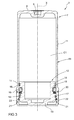
figure 3 shows a sectional view of a first embodiment of the hydraulic accumulator of the servo-control infigure 2 ; -
figure 4 shows a plan view of a detail of the hydraulic accumulator of the servo-control infigure 2 ; -
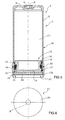
figure 5 shows a sectional view of a second embodiment of a hydraulic accumulator of the servo-control infigure 1 ; and -
figure 6 shows a plan view of a detail of the hydraulic accumulator of the servo-control infigure 5 . - In
figure 1 , reference numeral 1 indicates as a whole a servo-control for a gearbox, which is provided with a control shaft (not shown). Servo-control 1 comprises astoring tank 2 containing the control fluid (typically oil) at room pressure used by a number of hydraulic actuators (not shown) coupled to said control shaft and suited to axially displace the control shaft and to rotate the control shaft about a central axis. - Servo-control 1 comprises an electronic control unit ECU, which is suited to feedback-pilot the hydraulic actuators and transmit a linear and/or rotary motion to the control shaft as a function of the signals related to the axial and angular position of the control shaft, which are transmitted by a number of sensors facing the control shaft itself.
- Servo-control 1 comprises a
hydraulic accumulator 3 containing control fluid under pressure and a motor pump 4 which draws the control fluid from the storingtank 2 and feeds the control fluid under pressure to thehydraulic accumulator 3. - Finally, servo-control 1 comprises a number of
solenoid valves 5, which are adapted to selectively connect said hydraulic actuators to the storingtank 2 and to thehydraulic accumulator 3. - In particular, the hydraulic actuators are provided with a chamber (not shown) with which a respective three-
way solenoid valve 5 is associated. Each three-way solenoid valve 5 is suited to selectively serve a number of functions. In particular, saidsolenoid valve 5 is made for keeping the respective chamber insulated in order to keep the control fluid present inside the chamber itself constant; it is made for connecting the chamber to thestoring tank 2 for discharging the control fluid present inside the chamber; finally, it is made for connecting the chamber to thehydraulic accumulator 3 for feeding control fluid into the chamber. - In order to ensure a correct operation of the hydraulic actuators, i.e. to ensure that the hydraulic actuators provide their nominal performance, the pressure value of the control fluid inside the
hydraulic accumulator 3 is required to always be between a minimum value and a maximum value. Accordingly, the electronic control unit ECU is suited to actuate the motor pump 4 when the pressure value of the control fluid inside thestoring tank 2 is lower than the minimum value and to deactivate the motor pump 4 when the pressure value of the control fluid insidetank 2 is higher than the maximum value. - The electronic control unit ECU comprises an
assessment device 6 which is adapted to assess the pressure value of the control fluid inside thehydraulic accumulator 3 without resorting to a direct measurement of the pressure value itself (i.e. without using a dedicated pressure sensor). In particular, theassessment device 6 assesses the pressure value of the control fluid inside thehydraulic accumulator 3 as a function of a number of operating parameters of the motor pump 4 and of the hydraulic actuators. -
Figures 2 and3 show a first embodiment of thehydraulic accumulator 3 in detail. Thehydraulic accumulator 3 comprises anouter housing 7 made of a metal material having the shape of a cup-shaped body with cylindrical symmetry and provided with an axis X. Theouter housing 7 comprises anupper wall 8 provided with acentral recess 9. Moreover, theouter housing 7 comprises a lateralcylindrical wall 11 coaxial to axis X. - A
piston 12 is arranged, in use, inside theouter housing 7, which piston is made of a metal material, is axially sliding along axis X and mobile inside theouter housing 7. Piston 12 defines a variable-volume chamber C1 inside theouter housing 7 which, in a preliminary step of assembling thehydraulic accumulator 3, is filled with a gaseous material (preferably N2). Piston 12 further defines a variable-volume chamber C2 which is suited to be filled with the control fluid, where said two chambers C1 and C2 are separated bypiston 12. - Piston 12 is defined by a cylindrical symmetry body, coaxial to axis X and comprising a
base wall 13 and a lateralcylindrical wall 14. The lateralcylindrical wall 14 is provided with an outercylindrical surface 15 coaxial to axis X, the diameter of which approximates by defect the diameter of an innercylindrical surface 16 coaxial to axis X of theouter housing 7. - A number of
seats 17 are obtained on saidouter surface 15 of the piston, which are adapted to accommodate a plurality of annular-shaped gasket elements 18, coaxial to axis X, made of a plastic material and suited to allow the sliding ofpiston 12 inside theouter housing 7 to be improved and the control fluid leaks to be prevented. - According to a preferred variant, a pilot cut is obtained on an outer
cylindrical surface 19 of theouter housing 7 for accommodating asealing ring 20, and is coaxial to axis X and made of a plastic material. The sealingring 20 is arranged close to the open end of theouter housing 7. - As mentioned above,
piston 12 is made axially sliding along axis X and mobile inside theouter housing 7 between an upper limit stop position determined by theupper wall 8 of theouter housing 7 and a lower limit stop position. - The lower limit stop position is defined by the presence of the limit stop means 21. The limit stop means 21 in turn comprise a circlip 22 (also known as C-clip) having a substantially annular shape, coaxial to axis X and preferably made of elastic steel. The
circlip 22 is arranged in use inside a dedicated seat obtained in the innercylindrical surface 16 of theouter housing 7. The circlip 22 projects towards the inside of theouter housing 7 so as to act as striker element for thepiston 12 which slides therein. - As better shown in
figure 4 , it is worth noting thatcirclip 22 does not define a complete circumference but has anopening 23 which is made for optimizing the process of assembling thehydraulic accumulator 3. - According to the variant shown in
figure 4 , when in use (i.e., once thecirclip 22 has been inserted into the seat obtained in the outer housing 7), the opening 23 ofcirclip 22 has a size D smaller than or equal to 10 mm. According to a preferred embodiment, the opening 23 ofcirclip 22 inserted into its seat has a size smaller than 1 mm and preferably ranging from 0.6 mm to 1 mm. - The step of assembling the
hydraulic accumulator 3 takes place in an environment at a pressure of about 30 bar, in which chamber C1 is filled with a gaseous material (preferably N2) andpiston 12 is inserted intoouter housing 7. Oncepiston 12 has been inserted, thecirclip 22 is also fitted into the its dedicated seat. Since theopening 23 ofcirclip 22, when in use (i.e., once thecirclip 22 has been inserted into the seat obtained in the outer housing 7), is small in size, i.e. smaller than 10 mm, the two ends of thecirclip 22 itself must be diverted by slightly deforming it in order to allow the assembly operation. - The
hydraulic accumulator 3 shown infigure 3 is similar to that shown infigures 5 and 6 and the corresponding parts thereof are indicated, where possible, with the same reference numerals. - In particular, according to the embodiment shown in
figure 5 , the limit stop means 21 also comprise aperforated plate 24, which is interposed in use between theannular circlip 22 andpiston 12. As better shown infigure 6 , theperforated plate 24 has a discoid shape with a reduced thickness, is coaxial to axis X and has a diameter substantially approximating by defect the diameter of the innercylindrical surface 16 of theouter housing 7.Plate 24 has a number of through holes or openings which are such as to define a hydraulic narrowing for the control fluid in case of possible and undesired damage to the conduits downstream of thehydraulic accumulator 3. It is also worth noting that theperforated plate 24 is not provided with sealing elements and/or gaskets. - According to a preferred embodiment, the
perforated plate 24 has a single through opening, coaxial to axis X, which has such a size as to define a hydraulic narrowing for the control fluid in case of possible and undesired damage to the conduits downstream of thehydraulic accumulator 3. - It is also worth noting that, according to this variant, the
opening 23 ofcirclip 22 made for optimizing the process of assembling thehydraulic accumulator 3 may have a size smaller than or equal to 20 mm, preferably ranging from 14 mm to 20 mm. - Also in this case, the step of assembling the
hydraulic accumulator 3 takes place in an environment at a pressure of about 30 bar, in which chamber C1 is filled with a gaseous material (preferably N2) andpiston 12 is inserted into theouter housing 7. Oncepiston 17 has been inserted, theperforated plate 24 and then thecirclip 22 are also fitted into the dedicated seat thereof. According to this embodiment, since theopening 23 ofcirclip 22 has a size smaller than or equal to 20 mm, preferably ranging from 16 mm to 20 mm, diverting thecirclip 22 itself (by slightly deforming it before its insertion into the seat) is not required. - According to a further variant (not shown), the limit stop means 21 comprise the
perforated plate 24, which is interposed in use betweencirclip 22 andpiston 12. It is worth noting that according to this variant, in order to further improve the reliability ofhydraulic accumulator 3, theopening 23 ofcirclip 22 made for optimizing the process of assembling thehydraulic accumulator 3 when in use (i.e., once thecirclip 22 has been inserted into the seat obtained within the outer housing 7) has a size smaller than or equal to 10 mm. - Also in this case, the step of assembling the
hydraulic accumulator 3 takes place in an environment at a pressure of about 30 bar, in which the chamber is filled with a gaseous material (preferably N2) andpiston 12 is inserted into theouter housing 7. Oncepiston 12 has been inserted, theperforated plate 24 and then thecirclip 22 are also fitted. According to this embodiment, since theopening 23 ofcirclip 22, when in use (i.e., once thecirclip 22 has been inserted into the seat obtained in the outer housing 7), has a size smaller than or equal to 10 mm, the two ends of thecirclip 22 itself need to be diverted by slightly deforming it in order to insert it into its respective seat. - Due to the presence of the
perforated plate 24 and/or of the size of theopening 23 incirclip 22, if a traumatic and large damage occurs in the conduits downstream of thehydraulic accumulator 3 itself (e.g. a damage of about 10 mm in a piping that results in a considerable leakage of control fluid) and a considerable depression is thus generated, the travel ofpiston 12 is however stopped by the presence of the limit stop means 21. - It has been seen indeed that with an
opening 23 in thecirclip 22 which, when in use (i.e., once thecirclip 22 has been inserted into the seat obtained in the outer housing 7), has a size smaller than or equal to 10 mm, and/or with the presence of theperforated plate 24, the limit stop means 21 cannot be removed from the respective seat. - Thereby, damage to the whole hydraulic servo-control 1 can be avoided, and the above-described servo-control 1 is simultaneously cost-effective, easy to be implemented and reliable.
Claims (9)
- A hydraulic servo-control (1) of a servo-controlled gearbox comprising:a number of hydraulic actuators provided with respective chambers;a storing tank (2) containing control fluid used by the hydraulic actuators at room pressure;a hydraulic accumulator (3) containing control fluid under pressure;a motor pump (4), which draws the control fluid from the storing tank (2) and feeds the control fluid under pressure to the hydraulic accumulator (3); anda number of solenoid valves (5), which are suited to selectively connect the chambers of the hydraulic actuators to the storing tank (2) and to the hydraulic accumulator (3) ;the servo-control (1) is characterized in that the hydraulic accumulator (3) comprises an outer housing (7); and a piston (12), which is arranged inside the outer housing (7), manufactured so as to be axially sliding and mobile inside the outer housing (7) itself, and suited to define, inside the outer housing (7), a first variable-volume chamber (C1) for a gaseous material and a second variable-volume chamber (C2) for the control fluid under pressure; and limit stop means (21), which are arranged at an open end of the outer housing (7), act as a striker element for the piston (12), and comprise a circlip (22) with a substantially annular shape and a perforated plate (24) which, in use, is interposed between the circlip (22) and the piston (12).
- A servo-control according to claim 1, wherein the perforated plate (24) has a discoid shape with a reduced thickness and has a diameter substantially approximating by defect the size of an inner surface (16) of the outer housing (7), and has a number of through holes, which are such as to define a hydraulic narrowing for the control fluid.
- A servo-control according to claim 1 or 2, wherein the circlip (22) with a substantially annular shape has an opening (23).
- A servo-control according to claim 3, wherein the opening (23) has a size that is smaller than or equal to 10 mm, preferably smaller than or equal to 1 mm.
- A servo-control according to claim 3, wherein the opening (23) has a size that is smaller than or equal to 20 mm, preferably ranging from 14 mm to 20 mm.
- A servo-control according to any one of the preceding claims, wherein the circlip (22) with a substantially annular shape is housed in a seat obtained in an inner surface (16) of the outer housing (7), so as to project towards the inside of the outer housing (7).
- A servo-control according to any one of claims from 2 to 6, wherein the perforated plate (24) has an axis (X), and is provided with a single through opening, which is coaxial to the axis (X) and has such a size as to define a hydraulic narrowing for the control fluid.
- A servo-control according to any one of the preceding claims, wherein the perforated plate (24) is not provided with sealing elements and/or gaskets.
- A servo-control according to any one of the preceding claims, wherein the outer housing (7) has the shape of a cup-shaped body with cylindrical symmetry, is provided with an axis (X), and is provided with an upper wall (8) and with a lateral cylindrical wall (11), which is coaxial to the axis (X); and wherein an outer overall diameter of the piston (12) substantially approximates by defect the diameter of an inner cylindrical surface (16) of the outer housing (7), which surface is coaxial to the axis (X).
Applications Claiming Priority (1)
| Application Number | Priority Date | Filing Date | Title |
|---|---|---|---|
| IT000085A ITBO20120085A1 (en) | 2012-02-22 | 2012-02-22 | HYDRAULIC SERVO OF A SERVO-CHANGE |
Publications (2)
| Publication Number | Publication Date |
|---|---|
| EP2631494A1 true EP2631494A1 (en) | 2013-08-28 |
| EP2631494B1 EP2631494B1 (en) | 2015-01-14 |
Family
ID=45992668
Family Applications (1)
| Application Number | Title | Priority Date | Filing Date |
|---|---|---|---|
| EP13156466.8A Active EP2631494B1 (en) | 2012-02-22 | 2013-02-22 | Hydraulic servo-control of a servo-controlled gearbox |
Country Status (5)
| Country | Link |
|---|---|
| US (1) | US20140053542A1 (en) |
| EP (1) | EP2631494B1 (en) |
| CN (1) | CN103291907B (en) |
| BR (1) | BR102013004205B1 (en) |
| IT (1) | ITBO20120085A1 (en) |
Cited By (2)
| Publication number | Priority date | Publication date | Assignee | Title |
|---|---|---|---|---|
| US9574583B2 (en) | 2012-04-27 | 2017-02-21 | MAGNETI MARELLI S.p.A. | Hydraulic servo-control of a servo-controlled gearbox |
| IT201800010458A1 (en) * | 2018-11-20 | 2020-05-20 | Magneti Marelli Spa | HYDRAULIC ACCUMULATOR FOR A HYDRAULIC SERVO CONTROL OF A POWER OPERATED GEARBOX, HYDRAULIC ACTUATOR EQUIPPED WITH SAID ACCUMULATOR AND ASSEMBLY METHOD OF SAID ACCUMULATOR |
Families Citing this family (4)
| Publication number | Priority date | Publication date | Assignee | Title |
|---|---|---|---|---|
| JP6803271B2 (en) * | 2017-03-13 | 2020-12-23 | 日本発條株式会社 | accumulator |
| CN107013510A (en) * | 2017-04-27 | 2017-08-04 | 江苏创精锻有限公司 | A kind of vapour Vehicle Accumulator |
| CN115163583A (en) * | 2022-06-28 | 2022-10-11 | 杰锋汽车动力系统股份有限公司 | Energy accumulator structure for improving sealing performance |
| CN116423200B (en) * | 2023-04-11 | 2025-11-25 | 杰锋汽车动力系统股份有限公司 | An accumulator assembly device without an air valve and its usage method |
Citations (5)
| Publication number | Priority date | Publication date | Assignee | Title |
|---|---|---|---|---|
| US2884955A (en) * | 1956-06-27 | 1959-05-05 | Oscar A Yost | Liquid pipe line pressure compensator |
| US3198213A (en) * | 1962-12-21 | 1965-08-03 | Gen Precision Inc | Unit area ratio accumulator with fail-safe means |
| WO1997005410A1 (en) * | 1995-07-26 | 1997-02-13 | Ap Kongsberg Holdings Limited | Ratio selector mechanisms |
| US20040238054A1 (en) * | 2001-08-16 | 2004-12-02 | Norbert Weber | Piston-type accumulator |
| US20060204389A1 (en) * | 2003-03-25 | 2006-09-14 | Norbert Weber | Piston-type accumulator |
Family Cites Families (12)
| Publication number | Priority date | Publication date | Assignee | Title |
|---|---|---|---|---|
| GB810142A (en) * | 1955-08-10 | 1959-03-11 | Gratzmuller Jean Louis | Improvements relating to hydropneumatic accumulators |
| GB1183477A (en) * | 1967-09-15 | 1970-03-04 | Hydrotrole Ltd | Hydropneumatic Accumulator |
| US3875748A (en) * | 1973-11-26 | 1975-04-08 | Gen Motors Corp | Accumulator piston stop |
| US4041990A (en) * | 1976-04-05 | 1977-08-16 | The Bendix Corporation | Accumulator for use in a hydraulic system |
| JP2614236B2 (en) * | 1987-07-28 | 1997-05-28 | アイシン・エィ・ダブリュ株式会社 | Akyumulator |
| DE4202905A1 (en) * | 1992-02-01 | 1993-08-05 | Bosch Gmbh Robert | CYLINDERS, ESPECIALLY PRESSURE MEDIA FOR HYDRAULIC BRAKE SYSTEMS |
| DE19621021A1 (en) * | 1996-05-24 | 1997-10-02 | Daimler Benz Ag | Flow rate limiter for fuel injection system |
| JP3513096B2 (en) * | 2000-09-25 | 2004-03-31 | トヨタ自動車株式会社 | Accumulator and abnormality detection device for accumulator |
| DE10143830A1 (en) * | 2001-09-07 | 2003-03-27 | Zf Sachs Ag | Device for providing hydraulic medium under pressure, especially for operating motor vehicle clutch and/or gearbox, has controler for detecting and/or setting up tank empty state |
| DE102004018456A1 (en) * | 2004-04-16 | 2005-11-10 | Hydac Technology Gmbh | hydraulic accumulator |
| CN102114833B (en) * | 2009-12-31 | 2015-10-21 | 中国神华能源股份有限公司 | Drg is carried out to the system of fluid control |
| CN102221085B (en) * | 2010-04-15 | 2014-10-01 | 通用汽车环球科技运作公司 | Control system and method for shift fork position in dual clutch transmissions |
-
2012
- 2012-02-22 IT IT000085A patent/ITBO20120085A1/en unknown
-
2013
- 2013-02-21 US US13/773,115 patent/US20140053542A1/en not_active Abandoned
- 2013-02-22 EP EP13156466.8A patent/EP2631494B1/en active Active
- 2013-02-22 BR BR102013004205-6A patent/BR102013004205B1/en active IP Right Grant
- 2013-02-22 CN CN201310057466.0A patent/CN103291907B/en active Active
Patent Citations (5)
| Publication number | Priority date | Publication date | Assignee | Title |
|---|---|---|---|---|
| US2884955A (en) * | 1956-06-27 | 1959-05-05 | Oscar A Yost | Liquid pipe line pressure compensator |
| US3198213A (en) * | 1962-12-21 | 1965-08-03 | Gen Precision Inc | Unit area ratio accumulator with fail-safe means |
| WO1997005410A1 (en) * | 1995-07-26 | 1997-02-13 | Ap Kongsberg Holdings Limited | Ratio selector mechanisms |
| US20040238054A1 (en) * | 2001-08-16 | 2004-12-02 | Norbert Weber | Piston-type accumulator |
| US20060204389A1 (en) * | 2003-03-25 | 2006-09-14 | Norbert Weber | Piston-type accumulator |
Cited By (3)
| Publication number | Priority date | Publication date | Assignee | Title |
|---|---|---|---|---|
| US9574583B2 (en) | 2012-04-27 | 2017-02-21 | MAGNETI MARELLI S.p.A. | Hydraulic servo-control of a servo-controlled gearbox |
| EP2657533B1 (en) * | 2012-04-27 | 2019-09-18 | Magneti Marelli S.p.A. | Hydraulic servo-control of a servo-controlled gearbox |
| IT201800010458A1 (en) * | 2018-11-20 | 2020-05-20 | Magneti Marelli Spa | HYDRAULIC ACCUMULATOR FOR A HYDRAULIC SERVO CONTROL OF A POWER OPERATED GEARBOX, HYDRAULIC ACTUATOR EQUIPPED WITH SAID ACCUMULATOR AND ASSEMBLY METHOD OF SAID ACCUMULATOR |
Also Published As
| Publication number | Publication date |
|---|---|
| BR102013004205A2 (en) | 2014-04-29 |
| ITBO20120085A1 (en) | 2013-08-23 |
| BR102013004205B1 (en) | 2021-07-20 |
| CN103291907A (en) | 2013-09-11 |
| EP2631494B1 (en) | 2015-01-14 |
| US20140053542A1 (en) | 2014-02-27 |
| CN103291907B (en) | 2017-03-01 |
Similar Documents
| Publication | Publication Date | Title |
|---|---|---|
| EP2631494B1 (en) | Hydraulic servo-control of a servo-controlled gearbox | |
| EP2740977B1 (en) | Switching valve | |
| US20160230880A1 (en) | Hydraulic Control Device for an Automatic Transmission | |
| EP2631493A1 (en) | Hydraulic servo-control of a servo-controlled gearbox | |
| CN112789412A (en) | Hydraulic system with hydraulic servo drive for underwater use | |
| US20180287450A1 (en) | Electro-mechanical rotary actuator | |
| EP2698546A1 (en) | Four-state fluid cylinder, method of operating the same, and motor vehicle transmission | |
| EP2657533B1 (en) | Hydraulic servo-control of a servo-controlled gearbox | |
| US8122713B2 (en) | Hydraulic circuit of a servo-assisted mechanical transmission | |
| US7516691B2 (en) | Hydraulic linear drive, particularly a hydraulic transmission actuator | |
| EP2999907B1 (en) | Spring controlled valve | |
| US20160102754A1 (en) | Modular Control Device for a Transmission of a Commercial Vehicle | |
| CN109322939A (en) | Sensor integration for clutch release | |
| JP2008144817A (en) | Air operated valve | |
| EP1821005A1 (en) | Hydraulic servo for a gear change | |
| IT201800010458A1 (en) | HYDRAULIC ACCUMULATOR FOR A HYDRAULIC SERVO CONTROL OF A POWER OPERATED GEARBOX, HYDRAULIC ACTUATOR EQUIPPED WITH SAID ACCUMULATOR AND ASSEMBLY METHOD OF SAID ACCUMULATOR | |
| KR101712360B1 (en) | Double clutch actuator with hermeticity | |
| JP2019095033A (en) | Fluid cylinder and actuator having fluid cylinder | |
| KR20150129714A (en) | Piston with sealing pressed by pressure of an internal piston chamber | |
| JP2008544167A (en) | Torque transmission device | |
| JP2015140864A (en) | Centrifugal canceling structure of power transmission clutch for automatic transmission |
Legal Events
| Date | Code | Title | Description |
|---|---|---|---|
| PUAI | Public reference made under article 153(3) epc to a published international application that has entered the european phase |
Free format text: ORIGINAL CODE: 0009012 |
|
| 17P | Request for examination filed |
Effective date: 20130723 |
|
| AK | Designated contracting states |
Kind code of ref document: A1 Designated state(s): AL AT BE BG CH CY CZ DE DK EE ES FI FR GB GR HR HU IE IS IT LI LT LU LV MC MK MT NL NO PL PT RO RS SE SI SK SM TR |
|
| AX | Request for extension of the european patent |
Extension state: BA ME |
|
| REG | Reference to a national code |
Ref country code: DE Ref legal event code: R079 Ref document number: 602013000821 Country of ref document: DE Free format text: PREVIOUS MAIN CLASS: F15B0001240000 Ipc: F15B0001020000 |
|
| GRAP | Despatch of communication of intention to grant a patent |
Free format text: ORIGINAL CODE: EPIDOSNIGR1 |
|
| RIC1 | Information provided on ipc code assigned before grant |
Ipc: F15B 1/24 20060101ALI20140717BHEP Ipc: F16H 61/30 20060101ALI20140717BHEP Ipc: F15B 1/02 20060101AFI20140717BHEP Ipc: F16H 61/00 20060101ALI20140717BHEP |
|
| INTG | Intention to grant announced |
Effective date: 20140801 |
|
| GRAS | Grant fee paid |
Free format text: ORIGINAL CODE: EPIDOSNIGR3 |
|
| GRAA | (expected) grant |
Free format text: ORIGINAL CODE: 0009210 |
|
| AK | Designated contracting states |
Kind code of ref document: B1 Designated state(s): AL AT BE BG CH CY CZ DE DK EE ES FI FR GB GR HR HU IE IS IT LI LT LU LV MC MK MT NL NO PL PT RO RS SE SI SK SM TR |
|
| REG | Reference to a national code |
Ref country code: GB Ref legal event code: FG4D |
|
| REG | Reference to a national code |
Ref country code: CH Ref legal event code: EP |
|
| REG | Reference to a national code |
Ref country code: IE Ref legal event code: FG4D |
|
| REG | Reference to a national code |
Ref country code: AT Ref legal event code: REF Ref document number: 707217 Country of ref document: AT Kind code of ref document: T Effective date: 20150215 |
|
| REG | Reference to a national code |
Ref country code: DE Ref legal event code: R096 Ref document number: 602013000821 Country of ref document: DE Effective date: 20150226 |
|
| REG | Reference to a national code |
Ref country code: NL Ref legal event code: VDEP Effective date: 20150114 |
|
| REG | Reference to a national code |
Ref country code: AT Ref legal event code: MK05 Ref document number: 707217 Country of ref document: AT Kind code of ref document: T Effective date: 20150114 |
|
| REG | Reference to a national code |
Ref country code: LT Ref legal event code: MG4D |
|
| PG25 | Lapsed in a contracting state [announced via postgrant information from national office to epo] |
Ref country code: BE Free format text: LAPSE BECAUSE OF NON-PAYMENT OF DUE FEES Effective date: 20150228 |
|
| PG25 | Lapsed in a contracting state [announced via postgrant information from national office to epo] |
Ref country code: FI Free format text: LAPSE BECAUSE OF FAILURE TO SUBMIT A TRANSLATION OF THE DESCRIPTION OR TO PAY THE FEE WITHIN THE PRESCRIBED TIME-LIMIT Effective date: 20150114 Ref country code: HR Free format text: LAPSE BECAUSE OF FAILURE TO SUBMIT A TRANSLATION OF THE DESCRIPTION OR TO PAY THE FEE WITHIN THE PRESCRIBED TIME-LIMIT Effective date: 20150114 Ref country code: SE Free format text: LAPSE BECAUSE OF FAILURE TO SUBMIT A TRANSLATION OF THE DESCRIPTION OR TO PAY THE FEE WITHIN THE PRESCRIBED TIME-LIMIT Effective date: 20150114 Ref country code: NO Free format text: LAPSE BECAUSE OF FAILURE TO SUBMIT A TRANSLATION OF THE DESCRIPTION OR TO PAY THE FEE WITHIN THE PRESCRIBED TIME-LIMIT Effective date: 20150414 Ref country code: BG Free format text: LAPSE BECAUSE OF FAILURE TO SUBMIT A TRANSLATION OF THE DESCRIPTION OR TO PAY THE FEE WITHIN THE PRESCRIBED TIME-LIMIT Effective date: 20150414 Ref country code: ES Free format text: LAPSE BECAUSE OF FAILURE TO SUBMIT A TRANSLATION OF THE DESCRIPTION OR TO PAY THE FEE WITHIN THE PRESCRIBED TIME-LIMIT Effective date: 20150114 Ref country code: LT Free format text: LAPSE BECAUSE OF FAILURE TO SUBMIT A TRANSLATION OF THE DESCRIPTION OR TO PAY THE FEE WITHIN THE PRESCRIBED TIME-LIMIT Effective date: 20150114 |
|
| PG25 | Lapsed in a contracting state [announced via postgrant information from national office to epo] |
Ref country code: PL Free format text: LAPSE BECAUSE OF FAILURE TO SUBMIT A TRANSLATION OF THE DESCRIPTION OR TO PAY THE FEE WITHIN THE PRESCRIBED TIME-LIMIT Effective date: 20150114 Ref country code: NL Free format text: LAPSE BECAUSE OF FAILURE TO SUBMIT A TRANSLATION OF THE DESCRIPTION OR TO PAY THE FEE WITHIN THE PRESCRIBED TIME-LIMIT Effective date: 20150114 Ref country code: AT Free format text: LAPSE BECAUSE OF FAILURE TO SUBMIT A TRANSLATION OF THE DESCRIPTION OR TO PAY THE FEE WITHIN THE PRESCRIBED TIME-LIMIT Effective date: 20150114 Ref country code: RS Free format text: LAPSE BECAUSE OF FAILURE TO SUBMIT A TRANSLATION OF THE DESCRIPTION OR TO PAY THE FEE WITHIN THE PRESCRIBED TIME-LIMIT Effective date: 20150114 Ref country code: LV Free format text: LAPSE BECAUSE OF FAILURE TO SUBMIT A TRANSLATION OF THE DESCRIPTION OR TO PAY THE FEE WITHIN THE PRESCRIBED TIME-LIMIT Effective date: 20150114 Ref country code: GR Free format text: LAPSE BECAUSE OF FAILURE TO SUBMIT A TRANSLATION OF THE DESCRIPTION OR TO PAY THE FEE WITHIN THE PRESCRIBED TIME-LIMIT Effective date: 20150415 Ref country code: IS Free format text: LAPSE BECAUSE OF FAILURE TO SUBMIT A TRANSLATION OF THE DESCRIPTION OR TO PAY THE FEE WITHIN THE PRESCRIBED TIME-LIMIT Effective date: 20150514 |
|
| REG | Reference to a national code |
Ref country code: DE Ref legal event code: R097 Ref document number: 602013000821 Country of ref document: DE |
|
| PG25 | Lapsed in a contracting state [announced via postgrant information from national office to epo] |
Ref country code: CZ Free format text: LAPSE BECAUSE OF FAILURE TO SUBMIT A TRANSLATION OF THE DESCRIPTION OR TO PAY THE FEE WITHIN THE PRESCRIBED TIME-LIMIT Effective date: 20150114 Ref country code: EE Free format text: LAPSE BECAUSE OF FAILURE TO SUBMIT A TRANSLATION OF THE DESCRIPTION OR TO PAY THE FEE WITHIN THE PRESCRIBED TIME-LIMIT Effective date: 20150114 Ref country code: DK Free format text: LAPSE BECAUSE OF FAILURE TO SUBMIT A TRANSLATION OF THE DESCRIPTION OR TO PAY THE FEE WITHIN THE PRESCRIBED TIME-LIMIT Effective date: 20150114 Ref country code: RO Free format text: LAPSE BECAUSE OF FAILURE TO SUBMIT A TRANSLATION OF THE DESCRIPTION OR TO PAY THE FEE WITHIN THE PRESCRIBED TIME-LIMIT Effective date: 20150114 Ref country code: SK Free format text: LAPSE BECAUSE OF FAILURE TO SUBMIT A TRANSLATION OF THE DESCRIPTION OR TO PAY THE FEE WITHIN THE PRESCRIBED TIME-LIMIT Effective date: 20150114 Ref country code: MC Free format text: LAPSE BECAUSE OF FAILURE TO SUBMIT A TRANSLATION OF THE DESCRIPTION OR TO PAY THE FEE WITHIN THE PRESCRIBED TIME-LIMIT Effective date: 20150114 |
|
| REG | Reference to a national code |
Ref country code: IE Ref legal event code: MM4A |
|
| PLBE | No opposition filed within time limit |
Free format text: ORIGINAL CODE: 0009261 |
|
| STAA | Information on the status of an ep patent application or granted ep patent |
Free format text: STATUS: NO OPPOSITION FILED WITHIN TIME LIMIT |
|
| 26N | No opposition filed |
Effective date: 20151015 |
|
| REG | Reference to a national code |
Ref country code: FR Ref legal event code: PLFP Year of fee payment: 4 |
|
| PG25 | Lapsed in a contracting state [announced via postgrant information from national office to epo] |
Ref country code: IE Free format text: LAPSE BECAUSE OF NON-PAYMENT OF DUE FEES Effective date: 20150222 |
|
| PG25 | Lapsed in a contracting state [announced via postgrant information from national office to epo] |
Ref country code: SI Free format text: LAPSE BECAUSE OF FAILURE TO SUBMIT A TRANSLATION OF THE DESCRIPTION OR TO PAY THE FEE WITHIN THE PRESCRIBED TIME-LIMIT Effective date: 20150114 |
|
| PG25 | Lapsed in a contracting state [announced via postgrant information from national office to epo] |
Ref country code: BE Free format text: LAPSE BECAUSE OF FAILURE TO SUBMIT A TRANSLATION OF THE DESCRIPTION OR TO PAY THE FEE WITHIN THE PRESCRIBED TIME-LIMIT Effective date: 20150114 |
|
| REG | Reference to a national code |
Ref country code: CH Ref legal event code: PL |
|
| PG25 | Lapsed in a contracting state [announced via postgrant information from national office to epo] |
Ref country code: LI Free format text: LAPSE BECAUSE OF NON-PAYMENT OF DUE FEES Effective date: 20160229 Ref country code: CH Free format text: LAPSE BECAUSE OF NON-PAYMENT OF DUE FEES Effective date: 20160229 |
|
| PG25 | Lapsed in a contracting state [announced via postgrant information from national office to epo] |
Ref country code: MT Free format text: LAPSE BECAUSE OF FAILURE TO SUBMIT A TRANSLATION OF THE DESCRIPTION OR TO PAY THE FEE WITHIN THE PRESCRIBED TIME-LIMIT Effective date: 20150114 |
|
| REG | Reference to a national code |
Ref country code: FR Ref legal event code: PLFP Year of fee payment: 5 |
|
| PG25 | Lapsed in a contracting state [announced via postgrant information from national office to epo] |
Ref country code: HU Free format text: LAPSE BECAUSE OF FAILURE TO SUBMIT A TRANSLATION OF THE DESCRIPTION OR TO PAY THE FEE WITHIN THE PRESCRIBED TIME-LIMIT; INVALID AB INITIO Effective date: 20130222 |
|
| PG25 | Lapsed in a contracting state [announced via postgrant information from national office to epo] |
Ref country code: CY Free format text: LAPSE BECAUSE OF FAILURE TO SUBMIT A TRANSLATION OF THE DESCRIPTION OR TO PAY THE FEE WITHIN THE PRESCRIBED TIME-LIMIT Effective date: 20150114 |
|
| GBPC | Gb: european patent ceased through non-payment of renewal fee |
Effective date: 20170222 |
|
| PG25 | Lapsed in a contracting state [announced via postgrant information from national office to epo] |
Ref country code: LU Free format text: LAPSE BECAUSE OF NON-PAYMENT OF DUE FEES Effective date: 20150222 |
|
| REG | Reference to a national code |
Ref country code: FR Ref legal event code: PLFP Year of fee payment: 6 |
|
| PG25 | Lapsed in a contracting state [announced via postgrant information from national office to epo] |
Ref country code: GB Free format text: LAPSE BECAUSE OF NON-PAYMENT OF DUE FEES Effective date: 20170222 |
|
| PG25 | Lapsed in a contracting state [announced via postgrant information from national office to epo] |
Ref country code: SM Free format text: LAPSE BECAUSE OF FAILURE TO SUBMIT A TRANSLATION OF THE DESCRIPTION OR TO PAY THE FEE WITHIN THE PRESCRIBED TIME-LIMIT Effective date: 20150114 |
|
| PGFP | Annual fee paid to national office [announced via postgrant information from national office to epo] |
Ref country code: TR Payment date: 20180201 Year of fee payment: 6 |
|
| PG25 | Lapsed in a contracting state [announced via postgrant information from national office to epo] |
Ref country code: PT Free format text: LAPSE BECAUSE OF FAILURE TO SUBMIT A TRANSLATION OF THE DESCRIPTION OR TO PAY THE FEE WITHIN THE PRESCRIBED TIME-LIMIT Effective date: 20150114 Ref country code: MK Free format text: LAPSE BECAUSE OF FAILURE TO SUBMIT A TRANSLATION OF THE DESCRIPTION OR TO PAY THE FEE WITHIN THE PRESCRIBED TIME-LIMIT Effective date: 20150114 |
|
| PG25 | Lapsed in a contracting state [announced via postgrant information from national office to epo] |
Ref country code: AL Free format text: LAPSE BECAUSE OF FAILURE TO SUBMIT A TRANSLATION OF THE DESCRIPTION OR TO PAY THE FEE WITHIN THE PRESCRIBED TIME-LIMIT Effective date: 20150114 |
|
| PG25 | Lapsed in a contracting state [announced via postgrant information from national office to epo] |
Ref country code: TR Free format text: LAPSE BECAUSE OF NON-PAYMENT OF DUE FEES Effective date: 20190222 |
|
| PGFP | Annual fee paid to national office [announced via postgrant information from national office to epo] |
Ref country code: DE Payment date: 20260121 Year of fee payment: 14 |
|
| PGFP | Annual fee paid to national office [announced via postgrant information from national office to epo] |
Ref country code: IT Payment date: 20260121 Year of fee payment: 14 |
|
| PGFP | Annual fee paid to national office [announced via postgrant information from national office to epo] |
Ref country code: FR Payment date: 20260121 Year of fee payment: 14 |