EP2631483A1 - Hermetically sealed electric motor compressor - Google Patents
Hermetically sealed electric motor compressor Download PDFInfo
- Publication number
- EP2631483A1 EP2631483A1 EP11834187.4A EP11834187A EP2631483A1 EP 2631483 A1 EP2631483 A1 EP 2631483A1 EP 11834187 A EP11834187 A EP 11834187A EP 2631483 A1 EP2631483 A1 EP 2631483A1
- Authority
- EP
- European Patent Office
- Prior art keywords
- internal protector
- electric motor
- plastic insulating
- compressor
- insulating bobbins
- Prior art date
- Legal status (The legal status is an assumption and is not a legal conclusion. Google has not performed a legal analysis and makes no representation as to the accuracy of the status listed.)
- Granted
Links
Images


Classifications
-
- F—MECHANICAL ENGINEERING; LIGHTING; HEATING; WEAPONS; BLASTING
- F04—POSITIVE - DISPLACEMENT MACHINES FOR LIQUIDS; PUMPS FOR LIQUIDS OR ELASTIC FLUIDS
- F04B—POSITIVE-DISPLACEMENT MACHINES FOR LIQUIDS; PUMPS
- F04B39/00—Component parts, details, or accessories, of pumps or pumping systems specially adapted for elastic fluids, not otherwise provided for in, or of interest apart from, groups F04B25/00 - F04B37/00
- F04B39/12—Casings; Cylinders; Cylinder heads; Fluid connections
- F04B39/121—Casings
-
- F—MECHANICAL ENGINEERING; LIGHTING; HEATING; WEAPONS; BLASTING
- F04—POSITIVE - DISPLACEMENT MACHINES FOR LIQUIDS; PUMPS FOR LIQUIDS OR ELASTIC FLUIDS
- F04B—POSITIVE-DISPLACEMENT MACHINES FOR LIQUIDS; PUMPS
- F04B35/00—Piston pumps specially adapted for elastic fluids and characterised by the driving means to their working members, or by combination with, or adaptation to, specific driving engines or motors, not otherwise provided for
- F04B35/04—Piston pumps specially adapted for elastic fluids and characterised by the driving means to their working members, or by combination with, or adaptation to, specific driving engines or motors, not otherwise provided for the means being electric
-
- F—MECHANICAL ENGINEERING; LIGHTING; HEATING; WEAPONS; BLASTING
- F04—POSITIVE - DISPLACEMENT MACHINES FOR LIQUIDS; PUMPS FOR LIQUIDS OR ELASTIC FLUIDS
- F04C—ROTARY-PISTON, OR OSCILLATING-PISTON, POSITIVE-DISPLACEMENT MACHINES FOR LIQUIDS; ROTARY-PISTON, OR OSCILLATING-PISTON, POSITIVE-DISPLACEMENT PUMPS
- F04C23/00—Combinations of two or more pumps, each being of rotary-piston or oscillating-piston type, specially adapted for elastic fluids; Pumping installations specially adapted for elastic fluids; Multi-stage pumps specially adapted for elastic fluids
- F04C23/008—Hermetic pumps
-
- F—MECHANICAL ENGINEERING; LIGHTING; HEATING; WEAPONS; BLASTING
- F04—POSITIVE - DISPLACEMENT MACHINES FOR LIQUIDS; PUMPS FOR LIQUIDS OR ELASTIC FLUIDS
- F04C—ROTARY-PISTON, OR OSCILLATING-PISTON, POSITIVE-DISPLACEMENT MACHINES FOR LIQUIDS; ROTARY-PISTON, OR OSCILLATING-PISTON, POSITIVE-DISPLACEMENT PUMPS
- F04C28/00—Control of, monitoring of, or safety arrangements for, pumps or pumping installations specially adapted for elastic fluids
- F04C28/28—Safety arrangements; Monitoring
-
- F—MECHANICAL ENGINEERING; LIGHTING; HEATING; WEAPONS; BLASTING
- F04—POSITIVE - DISPLACEMENT MACHINES FOR LIQUIDS; PUMPS FOR LIQUIDS OR ELASTIC FLUIDS
- F04C—ROTARY-PISTON, OR OSCILLATING-PISTON, POSITIVE-DISPLACEMENT MACHINES FOR LIQUIDS; ROTARY-PISTON, OR OSCILLATING-PISTON, POSITIVE-DISPLACEMENT PUMPS
- F04C29/00—Component parts, details or accessories of pumps or pumping installations, not provided for in groups F04C18/00 - F04C28/00
- F04C29/0042—Driving elements, brakes, couplings, transmissions specially adapted for pumps
- F04C29/0085—Prime movers
-
- H—ELECTRICITY
- H02—GENERATION; CONVERSION OR DISTRIBUTION OF ELECTRIC POWER
- H02K—DYNAMO-ELECTRIC MACHINES
- H02K11/00—Structural association of dynamo-electric machines with electric components or with devices for shielding, monitoring or protection
- H02K11/20—Structural association of dynamo-electric machines with electric components or with devices for shielding, monitoring or protection for measuring, monitoring, testing, protecting or switching
- H02K11/25—Devices for sensing temperature, or actuated thereby
-
- H—ELECTRICITY
- H02—GENERATION; CONVERSION OR DISTRIBUTION OF ELECTRIC POWER
- H02K—DYNAMO-ELECTRIC MACHINES
- H02K11/00—Structural association of dynamo-electric machines with electric components or with devices for shielding, monitoring or protection
- H02K11/20—Structural association of dynamo-electric machines with electric components or with devices for shielding, monitoring or protection for measuring, monitoring, testing, protecting or switching
- H02K11/27—Devices for sensing current, or actuated thereby
-
- F—MECHANICAL ENGINEERING; LIGHTING; HEATING; WEAPONS; BLASTING
- F04—POSITIVE - DISPLACEMENT MACHINES FOR LIQUIDS; PUMPS FOR LIQUIDS OR ELASTIC FLUIDS
- F04C—ROTARY-PISTON, OR OSCILLATING-PISTON, POSITIVE-DISPLACEMENT MACHINES FOR LIQUIDS; ROTARY-PISTON, OR OSCILLATING-PISTON, POSITIVE-DISPLACEMENT PUMPS
- F04C18/00—Rotary-piston pumps specially adapted for elastic fluids
- F04C18/02—Rotary-piston pumps specially adapted for elastic fluids of arcuate-engagement type, i.e. with circular translatory movement of co-operating members, each member having the same number of teeth or tooth-equivalents
- F04C18/0207—Rotary-piston pumps specially adapted for elastic fluids of arcuate-engagement type, i.e. with circular translatory movement of co-operating members, each member having the same number of teeth or tooth-equivalents both members having co-operating elements in spiral form
- F04C18/0215—Rotary-piston pumps specially adapted for elastic fluids of arcuate-engagement type, i.e. with circular translatory movement of co-operating members, each member having the same number of teeth or tooth-equivalents both members having co-operating elements in spiral form where only one member is moving
-
- F—MECHANICAL ENGINEERING; LIGHTING; HEATING; WEAPONS; BLASTING
- F04—POSITIVE - DISPLACEMENT MACHINES FOR LIQUIDS; PUMPS FOR LIQUIDS OR ELASTIC FLUIDS
- F04C—ROTARY-PISTON, OR OSCILLATING-PISTON, POSITIVE-DISPLACEMENT MACHINES FOR LIQUIDS; ROTARY-PISTON, OR OSCILLATING-PISTON, POSITIVE-DISPLACEMENT PUMPS
- F04C2240/00—Components
- F04C2240/40—Electric motor
-
- H—ELECTRICITY
- H01—ELECTRIC ELEMENTS
- H01H—ELECTRIC SWITCHES; RELAYS; SELECTORS; EMERGENCY PROTECTIVE DEVICES
- H01H37/00—Thermally-actuated switches
- H01H37/02—Details
- H01H37/04—Bases; Housings; Mountings
- H01H37/043—Mountings on controlled apparatus
-
- H—ELECTRICITY
- H02—GENERATION; CONVERSION OR DISTRIBUTION OF ELECTRIC POWER
- H02K—DYNAMO-ELECTRIC MACHINES
- H02K3/00—Details of windings
- H02K3/32—Windings characterised by the shape, form or construction of the insulation
- H02K3/34—Windings characterised by the shape, form or construction of the insulation between conductors or between conductor and core, e.g. slot insulation
Definitions
- hooks for latching the internal protector are disposed, and the internal protector is fitted between the hooks and latched thereto.
- the above-described scroll compressor 7 takes in refrigerant gas taken into the sealed housing 2 (low-pressure housing) through an intake pipe 24 from an intake port 25 formed in the sealed housing 2 into the compression chamber 20 and compresses it to high-temperature, high-pressure gas.
- the compressed gas is discharged into the discharge chamber 5 through a discharge port 26 disposed at the center portion of the fixed scroll member 18 and a discharge valve 27 disposed in the discharge cover 3 and is then sent outside the compressor through a discharge pipe 28 connected to the discharge chamber 5.
- the internal protector 29 is fixedly installed using insulating bobbins 30 constituting the stator 8 of the electric motor 10.
- the insulating bobbins 30, which are used for forming the windings (coil formation) of the stator 8, as known in the art, are fitted onto a plurality of tooth parts (pole teeth) radially disposed on the stator core side, a stator winding wire 8A is wound around the insulating bobbins 30 using concentrated winding, and the insulating bobbins 30 are each configured to include a wound part 30A around which the stator winding wire 8A is wound, an inner circumferential flange 30B in contact with a pole core of the stator core, and an outer circumferential flange 30C in contact with a yoke core.
- the paired hooks 31 and 32 are provided, and the internal protector 29 is latched thereto by fitting it between the hooks 31 and 32. Consequently, by simply fitting the internal protector 29 between the hooks 31 and 32 disposed on the inner and outer circumferential flanges 30B and 30C of the plastic insulating bobbins 30, the internal protector 29 can be fixedly installed easily, thus improving the ease-of-assembly of the internal protector 29 and reducing the workload, thereby reducing costs.
- the internal protector 29 may have any configuration so long as it operates in response to at least the current and temperature to protect the electric motor 10.
- the plastic insulating bobbins 30 are not limited to plastic insulating bobbins having the shapes and materials exemplified in the above-described embodiments, and obviously, various modifications are possible.
Landscapes
- Engineering & Computer Science (AREA)
- Mechanical Engineering (AREA)
- General Engineering & Computer Science (AREA)
- Microelectronics & Electronic Packaging (AREA)
- Power Engineering (AREA)
- Compressor (AREA)
- Applications Or Details Of Rotary Compressors (AREA)
Abstract
Description
- The present invention relates to a hermetic electric compressor having a compressor and an electric motor configured to drive the compressor built into a sealed housing.
- With DC motors used for hermetic electric compressors, protection against overcurrent and abnormal temperature has been provided on the control side (inverter or software). However, recently, it has been pointed out that protection by software only is insufficient, and there is a tendency for mandatorily installing mechanical protection devices. Therefore, hermetic electric compressors are provided together with mechanical protection devices known as internal protectors. Such an internal protector, as described in, for example,
Patent Literature 1, opens a contact of a bi-metal switch by detecting an overcurrent or abnormal temperature when a current or temperature exceeds a reference value and protects the electric motor from fire damage, etc. by interrupting the electric circuit. - In addition, the above-described internal protector, as described in, for example,
Patent Literatures -
- {PTL 1} Japanese Unexamined Patent Application, Publication No.
2005-146951 - {PTL 2} Japanese Unexamined Patent Application, Publication No.
2003-83258 - {PTL 3} Japanese Unexamined Patent Application, Publication No.
2004-301039 - However, as described above, with a structure in which the internal protector is tied and fixed with a tying cord or the like, the internal protector must be tied onto the stator winding wire during assembly. Thus, there has been a problem of, for example, high production cost due to insufficient ease-of-assembly, as well as the extra workload required.
- The present invention has been conceived in light of such circumstances, and it is an object thereof to provide a hermetic electric compressor that can simplify the installation structure of the internal protector and improve the ease-of-assembly.
- To solve the above-mentioned problem, the hermetic electric compressor according to the present invention employs the following solutions.
Specifically, a hermetic electric compressor according to an aspect of the present invention is a hermetic electric compressor having a compressor and an electric motor configured to drive the compressor built into a sealed housing, wherein the electric motor includes a stator to which plastic insulating bobbins having flanges on an inner and outer circumferences of a plurality of tooth parts of a stator core are fitted and around which a stator winding wire is wound in concentrated winding around the plastic insulating bobbins, and wherein an internal protector for electric-motor protection is latched between the inner and outer circumferential flanges of the plastic insulating bobbins by being urged against the stator winding wire. - According to an aspect of the present invention, in the hermetic electric compressor, the electric motor includes a stator to which plastic insulating bobbins having flanges on the inner and outer circumferences of a plurality of tooth parts of a stator core are fitted and around which a stator winding wire is wound in concentrated winding around the plastic insulating bobbins, and an internal protector for electric-motor protection is latched between the inner and outer circumferential flanges of the plastic insulating bobbins by being urged against the stator winding wire. Thus, the internal protector, which operates in response to an overcurrent or abnormal temperature imposed on the electric motor to interrupt the electric circuit and thereby protect the electric motor, can be urged against the stator winding wire and fixedly installed between the flanges disposed on the inner and outer circumferences using the plastic insulating bobbins used for concentrated winding of the stator winding wire of the electric motor. Consequently, the installation structure of the internal protector can be simplified, improving the ease-of-assembly, and costs can be reduced by reducing the assembly workload.
- Moreover, in the hermetic electric compressor according to an aspect of the present invention, on the inner and outer circumferential flanges of the plastic insulating bobbins, hooks for latching the internal protector are disposed, and the internal protector is fitted between the hooks and latched thereto.
- According to an aspect of the present invention, on the inner and outer circumferential flanges of the plastic insulating bobbins, hooks for latching the internal protector are disposed, and the internal protector is fitted between the hooks and latched thereto. Thus, by fitting the internal protector between hooks disposed on the inner and outer circumferential flanges of the plastic insulating bobbins and latching it thereto with the hooks, the internal protector can be fixedly installed easily. Consequently, the ease-of-assembly of the internal protector can be improved, and the workload can be reduced, thereby reducing costs.
- Furthermore, in the hermetic electric compressor according to an aspect of the present invention, on the inner and outer circumferential flanges of the plastic insulating bobbins, latching holes are provided, and the internal protector is latched between the inner and outer circumferential flanges by means of retainer plates latched to the latching holes.
- According to an aspect of the present invention, on the inner and outer circumferential flanges of the plastic insulating bobbins, latching holes are formed, and the internal protector is latched between the inner and outer circumferential flanges by means of retainer plates latched to the latching holes.
Thus, by installing the internal protector between the inner and outer circumferential flanges of the plastic insulating bobbins and urging, from above, the internal protector by latching the retainer plates to the latching holes formed in the inner and outer circumferential flanges, the internal protector can be fixedly installed easily. Consequently, the ease-of-assembly of the internal protector can be improved, and the workload can be reduced, thereby reducing costs. - According to the present invention, the internal protector, which operates in response to an overcurrent or abnormal temperature imposed on the electric motor to interrupt the circuit and thereby protect the electric motor, can be urged against the stator winding wire and fixedly installed between the flanges disposed on the inner and outer circumferences using the plastic insulating bobbins used for concentrated-winding of the stator winding wire of the electric motor. Consequently, the installation structure of the internal protector can be simplified, improving the ease-of-assembly, and costs can be reduced by reducing the assembly workload.
-
- {
Fig. 1 }
Fig. 1 is a longitudinal sectional view of a hermetic electric compressor according to a first embodiment of the present invention. - {
Fig. 2 }
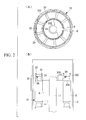
Fig. 2 is a plan view (A) and a longitudinal sectional view (B) of an electric motor built into the hermetic electric compressor shown inFig. 1 . - {
Fig. 3 }
Fig. 3 is a plan view (A) and a longitudinal sectional view (B) of an electric motor built into a hermetic electric compressor according to a second embodiment of the present invention. - Embodiments of the present invention will be described below with reference to the drawings.
- A first embodiment of the present invention will be described below using
Figs. 1 and2 .
Fig. 1 shows a longitudinal sectional view of a hermetic electric compressor according to the first embodiment of the present invention, andFig. 2 shows a plan view (A) and a longitudinal sectional view (B) of an electric motor thereof.
As a hermeticelectric compressor 1, here, an example of a hermeticelectric scroll compressor 1 is described, but the present invention is not limited thereto.
The hermeticelectric scroll compressor 1 includes a vertically-elongated, closed-bottom, cylindrical sealedhousing 2 composed of a steel plate. The upper portion of the sealedhousing 2 is sealed by adischarge cover 3 and anupper cover 4, and adischarge chamber 5 is formed between thedischarge cover 3 and theupper cover 4. - Inside the sealed
housing 2, an upper bearing member (frame member) 6 is fixedly installed to an upper region, and ascroll compressor 7 is installed on the upper bearingmember 6, while anelectric motor 10 constituted of astator 8 and arotor 9 is installed in a lower region by fixing thestator 8 to the sealedhousing 2. Acrank shaft 11 is fixed to therotor 9 of theelectric motor 10; acrank pin 12 whose shaft center is eccentrically shifted by a predetermined amount is disposed at an upper end of thecrank shaft 11; and by connecting thecrank pin 12 to thescroll compressor 7, it is possible to drive thescroll compressor 7. - As for the
crank shaft 11, the upper portion is supported by ajournal bearing part 6A of the upper bearingmember 6 in a freely rotating manner, and a lower end is supported in a freely rotating manner by a journallower bearing 13, which is disposed in the lower region of the sealedhousing 2. Adisplacement lubrication pump 14 is disposed between the journallower bearing 13 and the lower end of thecrank shaft 11 and is configured such that alubricant 15 filling the bottom portion of the sealedhousing 2 is taken in through anintake pipe 16 and discharged through alubrication hole 17 formed through thecrank shaft 11 along the axial direction. Thelubricant 15 is supplied to required sections, such as the upper bearingmember 6, thescroll compressor 7, and the journal lower bearing 13, through thelubrication hole 17. - The
scroll compressor 7 has the upper bearingmember 6 as one of the structural parts and includes a fixedscroll member 18 that is fixedly installed on the upper bearingmember 6; a turningscroll member 19 that is supported by athrust bearing part 6B of the upper bearingmember 6 in a freely sliding manner and constitutes acompression chamber 20 by being engaged with thefixed scroll member 18; ananti-rotation mechanism 21, such as an Oldham ring, that is interposed between the upper bearingmember 6 and the turningscroll member 19 to prevent rotation of the turningscroll member 19 while allowing revolving/turning motion; and adrive bush 22 and a turning bearing (needle bearing) 23 that are disposed between thecrank pin 12 of thecrank shaft 11 and a backside boss of the turningscroll member 19 and transmit the rotating force of thecrank shaft 11 to theturning scroll member 19. The end-plate center portion of the fixedscroll member 18 is installed on the upper bearingmember 6 while being connected to thedischarge cover 3. - The above-described
scroll compressor 7 takes in refrigerant gas taken into the sealed housing 2 (low-pressure housing) through anintake pipe 24 from anintake port 25 formed in the sealedhousing 2 into thecompression chamber 20 and compresses it to high-temperature, high-pressure gas. The compressed gas is discharged into thedischarge chamber 5 through adischarge port 26 disposed at the center portion of thefixed scroll member 18 and adischarge valve 27 disposed in thedischarge cover 3 and is then sent outside the compressor through adischarge pipe 28 connected to thedischarge chamber 5. - To prevent fire damage, etc. of the
electric motor 10 during overload operation of the hermeticelectric compressor 1, aninternal protector 29 for electric-motor protection is installed in thestator 8 of theelectric motor 10, as illustrated inFig. 2 . Theinternal protector 29 is a known protection device that is installed in a conductive circuit of theelectric motor 10 and interrupts the circuit in an emergency by operating in response to the current and temperature, and, for example, a known internal protector can be used, having a configuration including a bi-metal switch that detects the current value and ambient temperature and, when these exceed reference values (thresholds), opens a contact to interrupt the circuit. - The
internal protector 29 is fixedly installed usinginsulating bobbins 30 constituting thestator 8 of theelectric motor 10. Theinsulating bobbins 30, which are used for forming the windings (coil formation) of thestator 8, as known in the art, are fitted onto a plurality of tooth parts (pole teeth) radially disposed on the stator core side, astator winding wire 8A is wound around the insulatingbobbins 30 using concentrated winding, and the insulatingbobbins 30 are each configured to include awound part 30A around which thestator winding wire 8A is wound, an innercircumferential flange 30B in contact with a pole core of the stator core, and an outercircumferential flange 30C in contact with a yoke core. - The
insulating bobbins 30 are composed of plastic, and a plastic material such as fiberglass-reinforced composite PBT plastic (polybutylene terephthalate), PPS plastic (polyphenylene sulfide), or LCP plastic (liquid crystal polymer) can be used. On the innercircumferential flange 30B and the outercircumferential flange 30C of each plastic insulatingbobbin 30, pairedhooks internal protector 29 is fixedly installed are disposed and are configured such that, by fitting theinternal protector 29 between thehooks internal protector 29 is urged against thestator winding wire 8A and is latched thereto. - Accordingly, the following advantageous effects are achieved by this embodiment.
While the hermeticelectric compressor 1 is operating, for example, in an overload operation state, if an overcurrent flows through theelectric motor 10 and/or the ambient temperature reaches an abnormally high temperature, causing these to exceed reference values (thresholds), theelectric motor 10 can be protected from fire damage, etc. by operating theinternal protector 29 and interrupting the circuit by opening the contact of the bi-metal switch. By doing so, not only can theelectric motor 10 be protected by the control system through software but also a highly reliable protection mechanism can be constituted when combined with theinternal protector 29, which is a mechanical protection device. - Furthermore, for installing the
internal protector 29 in thestator 8 of theelectric motor 10, the plastic insulatingbobbins 30 used for concentrated winding of thestator winding wire 8A of theelectric motor 10 are used, and theinternal protector 29 is latched between theflanges stator winding wire 8A.
Thus, the installation structure of theinternal protector 29 can be simplified, and the ease-of-assembly can be significantly improved compared with known methods using tying cords or the like, and also, a significant cost reduction due to the decreased assembly workload can be expected. - In addition, to latch the
internal protector 29 between the inner and outercircumferential flanges bobbins 30, the paired hooks 31 and 32 are provided, and theinternal protector 29 is latched thereto by fitting it between thehooks internal protector 29 between thehooks circumferential flanges bobbins 30, theinternal protector 29 can be fixedly installed easily, thus improving the ease-of-assembly of theinternal protector 29 and reducing the workload, thereby reducing costs. - Next, a second embodiment of the present invention will be described using
Fig. 3 .
In this embodiment, compared with the above-described first embodiment, the latching structure of theinternal protector 29 differs. Since other points are similar to the first embodiment, descriptions thereof are omitted.
In this embodiment, instead of disposing the paired hooks 31 and 32 on the inner and outercircumferential flanges bobbins 30, paired latchingholes internal protector 29 is latched by being urged against thestator winding wire 8A between the inner and outercircumferential flanges bobbins 30 by means ofretainer plates 35 latched to the latching holes 33 and 34. - Through a configuration like that described above, by installing the
internal protector 29 between the inner and outercircumferential flanges bobbins 30 and urging, from above, theinternal protector 29 by latching theretainer plates 35 to the paired latchingholes circumferential flanges internal protector 29 can be fixedly installed easily. Consequently, in this embodiment too, similar to the first embodiment, the ease-of-assembly of theinternal protector 29 can be improved, and the workload can be reduced, thereby reducing costs. - The present invention is not limited to the invention associated with the above-described embodiments, and appropriate modifications are possible without departing from the spirit thereof. For example, in the above-described embodiment, an example in which the hermetic
electric scroll compressor 1 is applied has been described; however, the type of compressor is not limited to a scroll compressor, and it is obvious that it can be similarly applied to various types of compressors, such as a rotary compressor. - In addition, the
internal protector 29 may have any configuration so long as it operates in response to at least the current and temperature to protect theelectric motor 10. Similarly, the plastic insulatingbobbins 30 are not limited to plastic insulating bobbins having the shapes and materials exemplified in the above-described embodiments, and obviously, various modifications are possible. Reference Signs List -
- 1
- hermetic electric compressor (hermetic electric scroll compressor)
- 2
- sealed housing
- 7
- scroll compressor
- 8
- stator
- 8A
- stator winding wire
- 9
- rotor
- 10
- electric motor
- 29
- internal protector
- 30
- insulating bobbin (plastic insulating bobbin)
- 30B
- inner circumferential flange
- 30C
- outer circumferential flange
- 31, 32
- hook
- 33, 34
- latching hole
- 35
- retainer plate
Claims (3)
- A hermetic electric compressor having a compressor and an electric motor configured to drive the compressor built into a sealed housing, wherein the electric motor includes a stator to which plastic insulating bobbins having flanges on an inner and outer circumferences of a plurality of tooth parts of a stator core are fitted and around which a stator winding wire is wound in concentrated winding around the plastic insulating bobbins, wherein an internal protector for electric-motor protection is latched between the inner and outer circumferential flanges of the plastic insulating bobbins by being urged against the stator winding wire.
- The hermetic electric compressor according to Claim 1, wherein, on the inner and outer circumferential flanges of the plastic insulating bobbins, hooks for latching the internal protector are disposed, and the internal protector is fitted between the hooks and latched thereto.
- The hermetic electric compressor according to Claim 1, wherein, on the inner and outer circumferential flanges of the plastic insulating bobbins, latching holes are provided, and the internal protector is latched between the inner and outer circumferential flanges with retainer plates latched to the latching holes.
Applications Claiming Priority (2)
| Application Number | Priority Date | Filing Date | Title |
|---|---|---|---|
| JP2010234864A JP5693138B2 (en) | 2010-10-19 | 2010-10-19 | Hermetic electric compressor |
| PCT/JP2011/072821 WO2012053347A1 (en) | 2010-10-19 | 2011-10-04 | Hermetically sealed electric motor compressor |
Publications (3)
| Publication Number | Publication Date |
|---|---|
| EP2631483A1 true EP2631483A1 (en) | 2013-08-28 |
| EP2631483A4 EP2631483A4 (en) | 2018-01-10 |
| EP2631483B1 EP2631483B1 (en) | 2020-04-15 |
Family
ID=45975066
Family Applications (1)
| Application Number | Title | Priority Date | Filing Date |
|---|---|---|---|
| EP11834187.4A Active EP2631483B1 (en) | 2010-10-19 | 2011-10-04 | Hermetically sealed electric motor compressor |
Country Status (6)
| Country | Link |
|---|---|
| US (1) | US9273684B2 (en) |
| EP (1) | EP2631483B1 (en) |
| JP (1) | JP5693138B2 (en) |
| CN (1) | CN102918270B (en) |
| BR (1) | BR112012029486A2 (en) |
| WO (1) | WO2012053347A1 (en) |
Families Citing this family (9)
| Publication number | Priority date | Publication date | Assignee | Title |
|---|---|---|---|---|
| CN104113164B (en) * | 2013-07-17 | 2016-09-07 | 广东威灵电机制造有限公司 | The fixed structure of motor temperature controller and the motor of application thereof |
| JP6248704B2 (en) * | 2014-03-03 | 2017-12-20 | 株式会社豊田自動織機 | In-vehicle electric compressor |
| JP6282506B2 (en) * | 2014-03-26 | 2018-02-21 | サンデンホールディングス株式会社 | Electric compressor |
| JP6105511B2 (en) * | 2014-04-10 | 2017-03-29 | 三菱電機株式会社 | Heat pump equipment |
| TWI551010B (en) * | 2014-10-09 | 2016-09-21 | 建準電機工業股份有限公司 | Internal rotor motor |
| JP6426020B2 (en) * | 2015-02-09 | 2018-11-21 | 三菱重工サーマルシステムズ株式会社 | Sealed type electric compressor |
| JP2019011737A (en) * | 2017-06-30 | 2019-01-24 | 三菱重工サーマルシステムズ株式会社 | Compressor |
| CN112739911B (en) * | 2018-10-30 | 2023-07-25 | 法雷奥日本株式会社 | Reinforcing structure of electric compressor |
| US11382484B2 (en) | 2020-01-23 | 2022-07-12 | Haier Us Appliance Solutions, Inc. | Dishwashing appliance and electric motor for a fluid pump with a thermal-protection assembly |
Family Cites Families (25)
| Publication number | Priority date | Publication date | Assignee | Title |
|---|---|---|---|---|
| US3319096A (en) * | 1964-11-16 | 1967-05-09 | Westinghouse Electric Corp | Thermally protected dynamoelectric machine |
| US3959675A (en) * | 1974-06-19 | 1976-05-25 | Gould Inc. | Bobbin-flange mounted thermal protector for electric motors |
| US4112405A (en) * | 1976-08-16 | 1978-09-05 | Mark Joseph | Coil with protection against overheating |
| US4503347A (en) * | 1979-08-27 | 1985-03-05 | Copeland Corporation | Thermally protected dynamoelectric machine and method of assembly |
| JPH0749796B2 (en) | 1988-09-26 | 1995-05-31 | 三菱電機株式会社 | Hermetic electric compressor protector |
| JP2727686B2 (en) * | 1989-09-19 | 1998-03-11 | 松下電器産業株式会社 | Fixed structure of motor temperature protection device |
| JPH04168954A (en) | 1990-10-30 | 1992-06-17 | Matsushita Electric Ind Co Ltd | Stator of commutatorless motor |
| JP3627313B2 (en) * | 1995-03-29 | 2005-03-09 | 株式会社デンソー | Electromagnetic clutch |
| JPH0921385A (en) * | 1995-07-07 | 1997-01-21 | Mitsubishi Heavy Ind Ltd | Enclosed electric compressor |
| JP2921752B2 (en) * | 1996-09-18 | 1999-07-19 | ファナック株式会社 | Mounting method and mounting device for winding temperature detecting element of motor |
| JP4005169B2 (en) * | 1997-04-11 | 2007-11-07 | 東芝キヤリア株式会社 | Compressor |
| JPH1167558A (en) * | 1997-08-22 | 1999-03-09 | Tec Corp | Electromagnetic device |
| JPH11332155A (en) | 1998-05-08 | 1999-11-30 | Toshiba Corp | Motor stator and hermetic electric compressor |
| DE19852929C1 (en) * | 1998-11-17 | 2000-03-30 | Hanning Elektro Werke | Thermal switch for protecting electromagnetic coils in electric motor has connection lugs which enter receptacles of flat pinned plugs from inner surface of end flange of coil |
| JP3749389B2 (en) * | 1999-02-02 | 2006-02-22 | 東芝キヤリア株式会社 | Magnetizing method of motor for compressor |
| DE10002485A1 (en) * | 2000-01-21 | 2001-08-02 | Mannesmann Sachs Ag | Winding body for receiving a winding for an electro-magneto-mechanical converter and electro-magneto-mechanical converter |
| JP2003083258A (en) | 2001-09-05 | 2003-03-19 | Mitsubishi Electric Corp | Hermetic compressor |
| BRPI0307775B1 (en) * | 2002-02-19 | 2018-05-15 | Ubukata Industries Co., Ltd. | THERMALLY ACTIVATED KEY |
| ITPD20020094A1 (en) * | 2002-04-15 | 2003-10-15 | Inarca Spa | DEVICE FOR THE CONNECTION AND INSULATION OF A THERMAL PROTECTOR AND / OR A FUSE FOR ELECTRIC WINDINGS OF MOTORS. |
| JP2004301039A (en) | 2003-03-31 | 2004-10-28 | Mitsubishi Electric Corp | Protector for compressor and compressor using the same |
| JP3853779B2 (en) | 2003-11-13 | 2006-12-06 | 株式会社センサータ・テクノロジーズジャパン | Internal protector for hermetic electric compressor |
| KR101141964B1 (en) * | 2007-08-21 | 2012-05-04 | 우리산업 주식회사 | Field Coil Assembly of Electronic Clutch |
| EP2066008B1 (en) * | 2007-11-29 | 2011-08-03 | Siemens Aktiengesellschaft | Stator for a dynamo-electric machine with temperature gauging instruments |
| JP4790748B2 (en) * | 2008-04-09 | 2011-10-12 | 本田技研工業株式会社 | Stator and stator manufacturing apparatus |
| JP2010213527A (en) * | 2009-03-12 | 2010-09-24 | Daikin Ind Ltd | Stator, motor, and compressor |
-
2010
- 2010-10-19 JP JP2010234864A patent/JP5693138B2/en active Active
-
2011
- 2011-10-04 WO PCT/JP2011/072821 patent/WO2012053347A1/en not_active Ceased
- 2011-10-04 BR BR112012029486A patent/BR112012029486A2/en not_active Application Discontinuation
- 2011-10-04 EP EP11834187.4A patent/EP2631483B1/en active Active
- 2011-10-04 US US13/698,158 patent/US9273684B2/en active Active
- 2011-10-04 CN CN201180026682.8A patent/CN102918270B/en active Active
Non-Patent Citations (1)
| Title |
|---|
| See references of WO2012053347A1 * |
Also Published As
| Publication number | Publication date |
|---|---|
| US20130057120A1 (en) | 2013-03-07 |
| BR112012029486A2 (en) | 2017-02-21 |
| EP2631483A4 (en) | 2018-01-10 |
| JP2012087675A (en) | 2012-05-10 |
| WO2012053347A1 (en) | 2012-04-26 |
| JP5693138B2 (en) | 2015-04-01 |
| CN102918270B (en) | 2015-10-21 |
| CN102918270A (en) | 2013-02-06 |
| US9273684B2 (en) | 2016-03-01 |
| EP2631483B1 (en) | 2020-04-15 |
Similar Documents
| Publication | Publication Date | Title |
|---|---|---|
| US9273684B2 (en) | Hermetic electric compressor | |
| KR101319054B1 (en) | Electric compressor | |
| JP6377128B2 (en) | Manufacturing method of rotor | |
| CN103328823B (en) | Electric motor for compressor and use the motor compressor of this motor | |
| CN101617458B (en) | Motors and Compressors | |
| US9118234B2 (en) | Stator, motor, and compressor | |
| JP6257290B2 (en) | Hermetic electric compressor | |
| CN103122854A (en) | Compressor for vehicle | |
| US9853514B2 (en) | Interphase insulating sheets with voids at annular portions for rotating electric machine, rotating electric machine, and electric compressor for vehicle | |
| EP3109474A1 (en) | Electric scroll compressor | |
| US20120082573A1 (en) | Aluminum wound line-start brushless permanent magnet motor | |
| CN101517237A (en) | Rotation preventing member and scroll compressor | |
| EP4365449B1 (en) | Electric compressor | |
| JP2016217291A (en) | Electric compressor and its manufacturing method | |
| RU2472035C1 (en) | Scroll compressor | |
| JP2014077402A (en) | Vane type compressor | |
| CN101344082B (en) | Sealed compressor and freezing circulating device having the sealed compressor | |
| US7722334B2 (en) | Compressor and overload protecting apparatus | |
| EP4067660B1 (en) | Scroll compressor | |
| JP2009299524A (en) | Hermetically-sealed compressor | |
| JP2015195691A (en) | Motor and compressor | |
| US12571395B2 (en) | Compressor | |
| CN221448189U (en) | Electric compressor | |
| JP7038249B1 (en) | Compressor | |
| WO2025191302A1 (en) | Method for inspecting performance of internal protector for inverter compressor |
Legal Events
| Date | Code | Title | Description |
|---|---|---|---|
| PUAI | Public reference made under article 153(3) epc to a published international application that has entered the european phase |
Free format text: ORIGINAL CODE: 0009012 |
|
| 17P | Request for examination filed |
Effective date: 20121128 |
|
| AK | Designated contracting states |
Kind code of ref document: A1 Designated state(s): AL AT BE BG CH CY CZ DE DK EE ES FI FR GB GR HR HU IE IS IT LI LT LU LV MC MK MT NL NO PL PT RO RS SE SI SK SM TR |
|
| DAX | Request for extension of the european patent (deleted) | ||
| RAP1 | Party data changed (applicant data changed or rights of an application transferred) |
Owner name: MITSUBISHI HEAVY INDUSTRIES THERMAL SYSTEMS, LTD. |
|
| RA4 | Supplementary search report drawn up and despatched (corrected) |
Effective date: 20171207 |
|
| RIC1 | Information provided on ipc code assigned before grant |
Ipc: F04B 39/00 20060101AFI20171201BHEP Ipc: F04C 23/00 20060101ALI20171201BHEP Ipc: F04C 28/28 20060101ALI20171201BHEP Ipc: H01H 37/04 20060101ALI20171201BHEP Ipc: H02K 11/25 20160101ALI20171201BHEP Ipc: F04C 18/02 20060101ALI20171201BHEP Ipc: H02K 11/27 20160101ALI20171201BHEP Ipc: F04C 29/00 20060101ALI20171201BHEP |
|
| STAA | Information on the status of an ep patent application or granted ep patent |
Free format text: STATUS: EXAMINATION IS IN PROGRESS |
|
| 17Q | First examination report despatched |
Effective date: 20181012 |
|
| RIC1 | Information provided on ipc code assigned before grant |
Ipc: H02K 11/27 20160101ALI20171201BHEP Ipc: H02K 11/25 20160101ALI20171201BHEP Ipc: F04C 28/28 20060101ALI20171201BHEP Ipc: F04B 39/00 20060101AFI20171201BHEP Ipc: F04C 23/00 20060101ALI20171201BHEP Ipc: H01H 37/04 20060101ALI20171201BHEP Ipc: F04C 29/00 20060101ALI20171201BHEP Ipc: F04C 18/02 20060101ALI20171201BHEP |
|
| GRAP | Despatch of communication of intention to grant a patent |
Free format text: ORIGINAL CODE: EPIDOSNIGR1 |
|
| STAA | Information on the status of an ep patent application or granted ep patent |
Free format text: STATUS: GRANT OF PATENT IS INTENDED |
|
| INTG | Intention to grant announced |
Effective date: 20190410 |
|
| GRAJ | Information related to disapproval of communication of intention to grant by the applicant or resumption of examination proceedings by the epo deleted |
Free format text: ORIGINAL CODE: EPIDOSDIGR1 |
|
| STAA | Information on the status of an ep patent application or granted ep patent |
Free format text: STATUS: EXAMINATION IS IN PROGRESS |
|
| INTC | Intention to grant announced (deleted) | ||
| GRAR | Information related to intention to grant a patent recorded |
Free format text: ORIGINAL CODE: EPIDOSNIGR71 |
|
| GRAS | Grant fee paid |
Free format text: ORIGINAL CODE: EPIDOSNIGR3 |
|
| STAA | Information on the status of an ep patent application or granted ep patent |
Free format text: STATUS: GRANT OF PATENT IS INTENDED |
|
| INTG | Intention to grant announced |
Effective date: 20191015 |
|
| GRAA | (expected) grant |
Free format text: ORIGINAL CODE: 0009210 |
|
| STAA | Information on the status of an ep patent application or granted ep patent |
Free format text: STATUS: THE PATENT HAS BEEN GRANTED |
|
| AK | Designated contracting states |
Kind code of ref document: B1 Designated state(s): AL AT BE BG CH CY CZ DE DK EE ES FI FR GB GR HR HU IE IS IT LI LT LU LV MC MK MT NL NO PL PT RO RS SE SI SK SM TR |
|
| REG | Reference to a national code |
Ref country code: CH Ref legal event code: EP Ref country code: GB Ref legal event code: FG4D |
|
| REG | Reference to a national code |
Ref country code: DE Ref legal event code: R096 Ref document number: 602011066311 Country of ref document: DE |
|
| REG | Reference to a national code |
Ref country code: IE Ref legal event code: FG4D |
|
| REG | Reference to a national code |
Ref country code: AT Ref legal event code: REF Ref document number: 1257606 Country of ref document: AT Kind code of ref document: T Effective date: 20200515 |
|
| REG | Reference to a national code |
Ref country code: SE Ref legal event code: TRGR |
|
| REG | Reference to a national code |
Ref country code: NL Ref legal event code: MP Effective date: 20200415 |
|
| REG | Reference to a national code |
Ref country code: LT Ref legal event code: MG4D |
|
| PG25 | Lapsed in a contracting state [announced via postgrant information from national office to epo] |
Ref country code: NL Free format text: LAPSE BECAUSE OF FAILURE TO SUBMIT A TRANSLATION OF THE DESCRIPTION OR TO PAY THE FEE WITHIN THE PRESCRIBED TIME-LIMIT Effective date: 20200415 Ref country code: LT Free format text: LAPSE BECAUSE OF FAILURE TO SUBMIT A TRANSLATION OF THE DESCRIPTION OR TO PAY THE FEE WITHIN THE PRESCRIBED TIME-LIMIT Effective date: 20200415 Ref country code: NO Free format text: LAPSE BECAUSE OF FAILURE TO SUBMIT A TRANSLATION OF THE DESCRIPTION OR TO PAY THE FEE WITHIN THE PRESCRIBED TIME-LIMIT Effective date: 20200715 Ref country code: GR Free format text: LAPSE BECAUSE OF FAILURE TO SUBMIT A TRANSLATION OF THE DESCRIPTION OR TO PAY THE FEE WITHIN THE PRESCRIBED TIME-LIMIT Effective date: 20200716 Ref country code: IS Free format text: LAPSE BECAUSE OF FAILURE TO SUBMIT A TRANSLATION OF THE DESCRIPTION OR TO PAY THE FEE WITHIN THE PRESCRIBED TIME-LIMIT Effective date: 20200815 Ref country code: FI Free format text: LAPSE BECAUSE OF FAILURE TO SUBMIT A TRANSLATION OF THE DESCRIPTION OR TO PAY THE FEE WITHIN THE PRESCRIBED TIME-LIMIT Effective date: 20200415 Ref country code: PT Free format text: LAPSE BECAUSE OF FAILURE TO SUBMIT A TRANSLATION OF THE DESCRIPTION OR TO PAY THE FEE WITHIN THE PRESCRIBED TIME-LIMIT Effective date: 20200817 |
|
| REG | Reference to a national code |
Ref country code: AT Ref legal event code: MK05 Ref document number: 1257606 Country of ref document: AT Kind code of ref document: T Effective date: 20200415 |
|
| PG25 | Lapsed in a contracting state [announced via postgrant information from national office to epo] |
Ref country code: RS Free format text: LAPSE BECAUSE OF FAILURE TO SUBMIT A TRANSLATION OF THE DESCRIPTION OR TO PAY THE FEE WITHIN THE PRESCRIBED TIME-LIMIT Effective date: 20200415 Ref country code: HR Free format text: LAPSE BECAUSE OF FAILURE TO SUBMIT A TRANSLATION OF THE DESCRIPTION OR TO PAY THE FEE WITHIN THE PRESCRIBED TIME-LIMIT Effective date: 20200415 Ref country code: LV Free format text: LAPSE BECAUSE OF FAILURE TO SUBMIT A TRANSLATION OF THE DESCRIPTION OR TO PAY THE FEE WITHIN THE PRESCRIBED TIME-LIMIT Effective date: 20200415 Ref country code: BG Free format text: LAPSE BECAUSE OF FAILURE TO SUBMIT A TRANSLATION OF THE DESCRIPTION OR TO PAY THE FEE WITHIN THE PRESCRIBED TIME-LIMIT Effective date: 20200715 |
|
| PG25 | Lapsed in a contracting state [announced via postgrant information from national office to epo] |
Ref country code: AL Free format text: LAPSE BECAUSE OF FAILURE TO SUBMIT A TRANSLATION OF THE DESCRIPTION OR TO PAY THE FEE WITHIN THE PRESCRIBED TIME-LIMIT Effective date: 20200415 |
|
| REG | Reference to a national code |
Ref country code: DE Ref legal event code: R097 Ref document number: 602011066311 Country of ref document: DE |
|
| PG25 | Lapsed in a contracting state [announced via postgrant information from national office to epo] |
Ref country code: RO Free format text: LAPSE BECAUSE OF FAILURE TO SUBMIT A TRANSLATION OF THE DESCRIPTION OR TO PAY THE FEE WITHIN THE PRESCRIBED TIME-LIMIT Effective date: 20200415 Ref country code: IT Free format text: LAPSE BECAUSE OF FAILURE TO SUBMIT A TRANSLATION OF THE DESCRIPTION OR TO PAY THE FEE WITHIN THE PRESCRIBED TIME-LIMIT Effective date: 20200415 Ref country code: AT Free format text: LAPSE BECAUSE OF FAILURE TO SUBMIT A TRANSLATION OF THE DESCRIPTION OR TO PAY THE FEE WITHIN THE PRESCRIBED TIME-LIMIT Effective date: 20200415 Ref country code: ES Free format text: LAPSE BECAUSE OF FAILURE TO SUBMIT A TRANSLATION OF THE DESCRIPTION OR TO PAY THE FEE WITHIN THE PRESCRIBED TIME-LIMIT Effective date: 20200415 Ref country code: DK Free format text: LAPSE BECAUSE OF FAILURE TO SUBMIT A TRANSLATION OF THE DESCRIPTION OR TO PAY THE FEE WITHIN THE PRESCRIBED TIME-LIMIT Effective date: 20200415 Ref country code: SM Free format text: LAPSE BECAUSE OF FAILURE TO SUBMIT A TRANSLATION OF THE DESCRIPTION OR TO PAY THE FEE WITHIN THE PRESCRIBED TIME-LIMIT Effective date: 20200415 Ref country code: EE Free format text: LAPSE BECAUSE OF FAILURE TO SUBMIT A TRANSLATION OF THE DESCRIPTION OR TO PAY THE FEE WITHIN THE PRESCRIBED TIME-LIMIT Effective date: 20200415 Ref country code: CZ Free format text: LAPSE BECAUSE OF FAILURE TO SUBMIT A TRANSLATION OF THE DESCRIPTION OR TO PAY THE FEE WITHIN THE PRESCRIBED TIME-LIMIT Effective date: 20200415 |
|
| PLBE | No opposition filed within time limit |
Free format text: ORIGINAL CODE: 0009261 |
|
| STAA | Information on the status of an ep patent application or granted ep patent |
Free format text: STATUS: NO OPPOSITION FILED WITHIN TIME LIMIT |
|
| PG25 | Lapsed in a contracting state [announced via postgrant information from national office to epo] |
Ref country code: SK Free format text: LAPSE BECAUSE OF FAILURE TO SUBMIT A TRANSLATION OF THE DESCRIPTION OR TO PAY THE FEE WITHIN THE PRESCRIBED TIME-LIMIT Effective date: 20200415 Ref country code: PL Free format text: LAPSE BECAUSE OF FAILURE TO SUBMIT A TRANSLATION OF THE DESCRIPTION OR TO PAY THE FEE WITHIN THE PRESCRIBED TIME-LIMIT Effective date: 20200415 |
|
| 26N | No opposition filed |
Effective date: 20210118 |
|
| PG25 | Lapsed in a contracting state [announced via postgrant information from national office to epo] |
Ref country code: SI Free format text: LAPSE BECAUSE OF FAILURE TO SUBMIT A TRANSLATION OF THE DESCRIPTION OR TO PAY THE FEE WITHIN THE PRESCRIBED TIME-LIMIT Effective date: 20200415 |
|
| REG | Reference to a national code |
Ref country code: CH Ref legal event code: PL |
|
| PG25 | Lapsed in a contracting state [announced via postgrant information from national office to epo] |
Ref country code: LU Free format text: LAPSE BECAUSE OF NON-PAYMENT OF DUE FEES Effective date: 20201004 Ref country code: MC Free format text: LAPSE BECAUSE OF FAILURE TO SUBMIT A TRANSLATION OF THE DESCRIPTION OR TO PAY THE FEE WITHIN THE PRESCRIBED TIME-LIMIT Effective date: 20200415 |
|
| REG | Reference to a national code |
Ref country code: BE Ref legal event code: MM Effective date: 20201031 |
|
| PG25 | Lapsed in a contracting state [announced via postgrant information from national office to epo] |
Ref country code: BE Free format text: LAPSE BECAUSE OF NON-PAYMENT OF DUE FEES Effective date: 20201031 Ref country code: CH Free format text: LAPSE BECAUSE OF NON-PAYMENT OF DUE FEES Effective date: 20201031 Ref country code: LI Free format text: LAPSE BECAUSE OF NON-PAYMENT OF DUE FEES Effective date: 20201031 |
|
| PG25 | Lapsed in a contracting state [announced via postgrant information from national office to epo] |
Ref country code: IE Free format text: LAPSE BECAUSE OF NON-PAYMENT OF DUE FEES Effective date: 20201004 |
|
| PG25 | Lapsed in a contracting state [announced via postgrant information from national office to epo] |
Ref country code: TR Free format text: LAPSE BECAUSE OF FAILURE TO SUBMIT A TRANSLATION OF THE DESCRIPTION OR TO PAY THE FEE WITHIN THE PRESCRIBED TIME-LIMIT Effective date: 20200415 Ref country code: MT Free format text: LAPSE BECAUSE OF FAILURE TO SUBMIT A TRANSLATION OF THE DESCRIPTION OR TO PAY THE FEE WITHIN THE PRESCRIBED TIME-LIMIT Effective date: 20200415 Ref country code: CY Free format text: LAPSE BECAUSE OF FAILURE TO SUBMIT A TRANSLATION OF THE DESCRIPTION OR TO PAY THE FEE WITHIN THE PRESCRIBED TIME-LIMIT Effective date: 20200415 |
|
| PG25 | Lapsed in a contracting state [announced via postgrant information from national office to epo] |
Ref country code: MK Free format text: LAPSE BECAUSE OF FAILURE TO SUBMIT A TRANSLATION OF THE DESCRIPTION OR TO PAY THE FEE WITHIN THE PRESCRIBED TIME-LIMIT Effective date: 20200415 |
|
| REG | Reference to a national code |
Ref country code: DE Ref legal event code: R082 Ref document number: 602011066311 Country of ref document: DE Representative=s name: CBDL PATENTANWAELTE GBR, DE Ref country code: DE Ref legal event code: R082 Ref document number: 602011066311 Country of ref document: DE Representative=s name: CBDL PATENTANWAELTE EGBR, DE |
|
| PGFP | Annual fee paid to national office [announced via postgrant information from national office to epo] |
Ref country code: GB Payment date: 20250828 Year of fee payment: 15 |
|
| PGFP | Annual fee paid to national office [announced via postgrant information from national office to epo] |
Ref country code: FR Payment date: 20250908 Year of fee payment: 15 |
|
| PGFP | Annual fee paid to national office [announced via postgrant information from national office to epo] |
Ref country code: SE Payment date: 20250910 Year of fee payment: 15 |
|
| PGFP | Annual fee paid to national office [announced via postgrant information from national office to epo] |
Ref country code: DE Payment date: 20250902 Year of fee payment: 15 |