EP2631464A1 - Fuel injection pump including a variable pressure compartment - Google Patents
Fuel injection pump including a variable pressure compartment Download PDFInfo
- Publication number
- EP2631464A1 EP2631464A1 EP11834506.5A EP11834506A EP2631464A1 EP 2631464 A1 EP2631464 A1 EP 2631464A1 EP 11834506 A EP11834506 A EP 11834506A EP 2631464 A1 EP2631464 A1 EP 2631464A1
- Authority
- EP
- European Patent Office
- Prior art keywords
- pressure adjustment
- piston
- cylinder
- pressure
- fuel injection
- Prior art date
- Legal status (The legal status is an assumption and is not a legal conclusion. Google has not performed a legal analysis and makes no representation as to the accuracy of the status listed.)
- Granted
Links
- 239000000446 fuel Substances 0.000 title claims abstract description 76
- 238000002347 injection Methods 0.000 title claims abstract description 51
- 239000007924 injection Substances 0.000 title claims abstract description 51
- 238000003780 insertion Methods 0.000 claims abstract description 7
- 230000037431 insertion Effects 0.000 claims abstract description 7
- 238000003825 pressing Methods 0.000 claims abstract description 7
- 230000011664 signaling Effects 0.000 claims description 6
- 238000004519 manufacturing process Methods 0.000 abstract description 4
- 238000002485 combustion reaction Methods 0.000 description 8
- 230000000694 effects Effects 0.000 description 6
- 238000000034 method Methods 0.000 description 5
- 230000003247 decreasing effect Effects 0.000 description 3
- 238000003912 environmental pollution Methods 0.000 description 2
- 238000007789 sealing Methods 0.000 description 2
- 230000003111 delayed effect Effects 0.000 description 1
- 239000000295 fuel oil Substances 0.000 description 1
- 239000010763 heavy fuel oil Substances 0.000 description 1
- 239000000463 material Substances 0.000 description 1
- 238000012986 modification Methods 0.000 description 1
- 230000004048 modification Effects 0.000 description 1
- 239000010747 number 6 fuel oil Substances 0.000 description 1
- 230000010349 pulsation Effects 0.000 description 1
- 239000000243 solution Substances 0.000 description 1
- 239000000126 substance Substances 0.000 description 1
Images


Classifications
-
- F—MECHANICAL ENGINEERING; LIGHTING; HEATING; WEAPONS; BLASTING
- F04—POSITIVE - DISPLACEMENT MACHINES FOR LIQUIDS; PUMPS FOR LIQUIDS OR ELASTIC FLUIDS
- F04B—POSITIVE-DISPLACEMENT MACHINES FOR LIQUIDS; PUMPS
- F04B49/00—Control, e.g. of pump delivery, or pump pressure of, or safety measures for, machines, pumps, or pumping installations, not otherwise provided for, or of interest apart from, groups F04B1/00 - F04B47/00
- F04B49/12—Control, e.g. of pump delivery, or pump pressure of, or safety measures for, machines, pumps, or pumping installations, not otherwise provided for, or of interest apart from, groups F04B1/00 - F04B47/00 by varying the length of stroke of the working members
-
- F—MECHANICAL ENGINEERING; LIGHTING; HEATING; WEAPONS; BLASTING
- F02—COMBUSTION ENGINES; HOT-GAS OR COMBUSTION-PRODUCT ENGINE PLANTS
- F02M—SUPPLYING COMBUSTION ENGINES IN GENERAL WITH COMBUSTIBLE MIXTURES OR CONSTITUENTS THEREOF
- F02M59/00—Pumps specially adapted for fuel-injection and not provided for in groups F02M39/00 -F02M57/00, e.g. rotary cylinder-block type of pumps
- F02M59/02—Pumps specially adapted for fuel-injection and not provided for in groups F02M39/00 -F02M57/00, e.g. rotary cylinder-block type of pumps of reciprocating-piston or reciprocating-cylinder type
- F02M59/022—Pumps specially adapted for fuel-injection and not provided for in groups F02M39/00 -F02M57/00, e.g. rotary cylinder-block type of pumps of reciprocating-piston or reciprocating-cylinder type having an accumulator storing pressurised fuel during pumping stroke of the piston for subsequent delivery to the injector
-
- F—MECHANICAL ENGINEERING; LIGHTING; HEATING; WEAPONS; BLASTING
- F02—COMBUSTION ENGINES; HOT-GAS OR COMBUSTION-PRODUCT ENGINE PLANTS
- F02M—SUPPLYING COMBUSTION ENGINES IN GENERAL WITH COMBUSTIBLE MIXTURES OR CONSTITUENTS THEREOF
- F02M59/00—Pumps specially adapted for fuel-injection and not provided for in groups F02M39/00 -F02M57/00, e.g. rotary cylinder-block type of pumps
- F02M59/20—Varying fuel delivery in quantity or timing
- F02M59/205—Quantity of fuel admitted to pumping elements being metered by an auxiliary metering device
-
- F—MECHANICAL ENGINEERING; LIGHTING; HEATING; WEAPONS; BLASTING
- F02—COMBUSTION ENGINES; HOT-GAS OR COMBUSTION-PRODUCT ENGINE PLANTS
- F02M—SUPPLYING COMBUSTION ENGINES IN GENERAL WITH COMBUSTIBLE MIXTURES OR CONSTITUENTS THEREOF
- F02M59/00—Pumps specially adapted for fuel-injection and not provided for in groups F02M39/00 -F02M57/00, e.g. rotary cylinder-block type of pumps
- F02M59/20—Varying fuel delivery in quantity or timing
- F02M59/22—Varying quantity or timing by adjusting cylinder-head space
-
- F—MECHANICAL ENGINEERING; LIGHTING; HEATING; WEAPONS; BLASTING
- F02—COMBUSTION ENGINES; HOT-GAS OR COMBUSTION-PRODUCT ENGINE PLANTS
- F02M—SUPPLYING COMBUSTION ENGINES IN GENERAL WITH COMBUSTIBLE MIXTURES OR CONSTITUENTS THEREOF
- F02M59/00—Pumps specially adapted for fuel-injection and not provided for in groups F02M39/00 -F02M57/00, e.g. rotary cylinder-block type of pumps
- F02M59/44—Details, components parts, or accessories not provided for in, or of interest apart from, the apparatus of groups F02M59/02 - F02M59/42; Pumps having transducers, e.g. to measure displacement of pump rack or piston
- F02M59/46—Valves
- F02M59/462—Delivery valves
-
- F—MECHANICAL ENGINEERING; LIGHTING; HEATING; WEAPONS; BLASTING
- F04—POSITIVE - DISPLACEMENT MACHINES FOR LIQUIDS; PUMPS FOR LIQUIDS OR ELASTIC FLUIDS
- F04B—POSITIVE-DISPLACEMENT MACHINES FOR LIQUIDS; PUMPS
- F04B1/00—Multi-cylinder machines or pumps characterised by number or arrangement of cylinders
- F04B1/04—Multi-cylinder machines or pumps characterised by number or arrangement of cylinders having cylinders in star- or fan-arrangement
- F04B1/053—Multi-cylinder machines or pumps characterised by number or arrangement of cylinders having cylinders in star- or fan-arrangement with actuating or actuated elements at the inner ends of the cylinders
-
- F—MECHANICAL ENGINEERING; LIGHTING; HEATING; WEAPONS; BLASTING
- F04—POSITIVE - DISPLACEMENT MACHINES FOR LIQUIDS; PUMPS FOR LIQUIDS OR ELASTIC FLUIDS
- F04B—POSITIVE-DISPLACEMENT MACHINES FOR LIQUIDS; PUMPS
- F04B11/00—Equalisation of pulses, e.g. by use of air vessels; Counteracting cavitation
- F04B11/0008—Equalisation of pulses, e.g. by use of air vessels; Counteracting cavitation using accumulators
- F04B11/0016—Equalisation of pulses, e.g. by use of air vessels; Counteracting cavitation using accumulators with a fluid spring
-
- F—MECHANICAL ENGINEERING; LIGHTING; HEATING; WEAPONS; BLASTING
- F04—POSITIVE - DISPLACEMENT MACHINES FOR LIQUIDS; PUMPS FOR LIQUIDS OR ELASTIC FLUIDS
- F04B—POSITIVE-DISPLACEMENT MACHINES FOR LIQUIDS; PUMPS
- F04B11/00—Equalisation of pulses, e.g. by use of air vessels; Counteracting cavitation
- F04B11/0008—Equalisation of pulses, e.g. by use of air vessels; Counteracting cavitation using accumulators
- F04B11/0033—Equalisation of pulses, e.g. by use of air vessels; Counteracting cavitation using accumulators with a mechanical spring
-
- F—MECHANICAL ENGINEERING; LIGHTING; HEATING; WEAPONS; BLASTING
- F04—POSITIVE - DISPLACEMENT MACHINES FOR LIQUIDS; PUMPS FOR LIQUIDS OR ELASTIC FLUIDS
- F04B—POSITIVE-DISPLACEMENT MACHINES FOR LIQUIDS; PUMPS
- F04B49/00—Control, e.g. of pump delivery, or pump pressure of, or safety measures for, machines, pumps, or pumping installations, not otherwise provided for, or of interest apart from, groups F04B1/00 - F04B47/00
- F04B49/16—Control, e.g. of pump delivery, or pump pressure of, or safety measures for, machines, pumps, or pumping installations, not otherwise provided for, or of interest apart from, groups F04B1/00 - F04B47/00 by adjusting the capacity of dead spaces of working chambers
-
- F—MECHANICAL ENGINEERING; LIGHTING; HEATING; WEAPONS; BLASTING
- F04—POSITIVE - DISPLACEMENT MACHINES FOR LIQUIDS; PUMPS FOR LIQUIDS OR ELASTIC FLUIDS
- F04B—POSITIVE-DISPLACEMENT MACHINES FOR LIQUIDS; PUMPS
- F04B7/00—Piston machines or pumps characterised by having positively-driven valving
Definitions
- the present invention relates to a fuel injection pump having a variable pressure chamber and, more particularly, to a fuel injection pump having a variable pressure chamber in which a pressure of the variable pressure chamber, which can adjust a distance of an upward and downward reciprocating motion of a piston, is adjusted through a manual pressure adjustment unit or an automatic pressure adjustment unit to adjust a volume of the variable pressure chamber such that a fuel injection timing is delayed or advanced to improve fuel efficiency as well as generation of NOx is reduced while smog which is a harmful gas is reduced at the same time.
- an ignition delay phenomenon may occur due to a use of bunker-C (HFO) having a different viscosity for each fuel such that compensation is needed for a combustion loss, and a technique for compensating the combustion loss is, in a large sense, collectively called as a variable injection timing (VIT) technique and, in substance, refers to a technique which achieves optimized combustion by performing compensation using fuel quality setting (FQS).
- HFO bunker-C
- FQS fuel quality setting
- VIT or the FQS described above is used for purpose of reducing a fuel cost while improving combustion efficiency by increasing a maximum combustion pressure within a combustion cylinder.
- the VIT may automatically adjust an injection timing during an operation of an engine and allows optimal fuel consumption at a low load.
- a plunger blocks a spill port of a barrel such that a pressure of fuel begins to rise and fuel of a high pressure is injected, and in this case, in order to control a fuel injection start timing, a location of the spill port formed on the barrel is adjusted vertically or a shape of the plunger is modified according to a load.
- an objective of the present invention is to provide a fuel injection pump having a variable pressure chamber which can adjust a fuel injection timing according to each engine load with a simple structure and a lower manufacture cost compared to the conventional injection pump without modifying a shape of a plunger as well as obviating a separate apparatus for moving a barrel.
- the present invention directed to achieve the above objective includes a barrel inserted and installed within a pump housing; a plunger slidably coupled to an inside of the barrel; and an upper cover coupled to an upper surface of the pump housing, wherein the plunger closes a discharge hole of the barrel to begin a pressure increase of fuel to inject high pressure fuel, the fuel injection pump further including: a pressure adjustment means comprising: a contact plug of which lower portion is inserted and installed in the upper cover; a cylinder of which lower portion is inserted and installed in the contact plug and having the variable pressure chamber formed inside thereof; a main fuel pressing hole formed in the upper cover and the barrel to connect the variable pressure chamber of the cylinder and a plunger insertion hole of the barrel; a piston installed in the variable pressure chamber of the cylinder to enable an upward and downward sliding motion thereof; and a manual pressure adjustment unit installed on an upper portion of the cylinder to enable a vertical height adjustment to elastically support an upper portion of the piston.
- a pressure adjustment means comprising: a contact plug of which lower portion is
- the pressure adjustment means may further include an automatic pressure adjustment unit connected to an air inflow groove which penetrates the cylinder and the contact plug to be positioned above the piston and to automatically adjust a location of the piston.
- the automatic pressure adjustment unit may include an air pressure supplier connected to the air inflow groove, which penetrates the cylinder and the contact plug, through an air pressure supplier connection line to be located above the piston; a variable pressure valve installed on the air pressure supplier connection line; and an engine load signaling device connected to the variable pressure valve and an engine.
- the manual pressure adjustment means may include a pressure adjustment screw which is screw coupled to the upper portion of the cylinder to be located above the piston, a vertical height of the pressure adjustment screw being adjustable; an elastic member interposed between the piston and the pressure adjustment screw to elastically support the piston with respect to the pressure adjustment screw; and a fixing nut which closely contacts an upper surface of the cylinder and is screw coupled to an upper portion of the pressure adjustment screw to fix the pressure adjustment screw.
- a vertical height of a pressure adjustment screw of a manual pressure adjustment unit or adjusting an air pressure supplied by an air pressure supplier of an automatic pressure adjustment unit a distance of a reciprocating motion of a piston and a bush is adjusted so that a volume of the variable pressure chamber is adjusted to achieve an effect of delaying a fuel cam, thereby delaying or advancing a fuel injection timing of a fuel injection pump.
- a fuel injection pump having a variable pressure chamber is highly useful since the present invention does not have a separate apparatus for moving a barrel and, without modifying a shape of a plunger, may perform complete combustion to achieve an effect of lowering a fuel cost with a simple structure and a lower manufacture cost compared to the conventional injection pump and may reduce generation of NOx while reducing smog which is a harmful gas by adjusting a fuel injection timing according to each engine load, thereby achieving an effect of reducing environmental pollution.
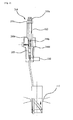
- FIG. 1 is a view for explaining a fuel injection pump according to the present invention.
- FIG. 2 is a view for explaining a manual pressure adjustment unit of a fuel injection pump according to the present invention.
- FIG. 3 is a view for explaining an automatic pressure adjustment unit of a fuel injection pump according to the present invention.
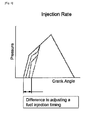
- FIG. 4 is a fuel injection rate variable graph according to a location of a variable pressure chamber according to the present invention.
- variable pressure chamber 142 main fuel pressing hole
- sealing ring 145 automatic pressure adjustment unit
- variable pressure valve 145d engine load signaling device
- FIG. 1 is a view for explaining a fuel injection pump according to the present invention
- FIG. 2 is a view for explaining a manual pressure adjustment unit of a fuel injection pump according to the present invention
- FIG. 3 is a view for explaining an automatic pressure adjustment unit of a fuel injection pump according to the present invention.
- a fuel injection pump includes a barrel 11 which is inserted and installed within a pump housing 10, wherein a plunger insertion hole 110 is formed inside thereof, a plunger 12 which is slidably coupled to an inside of the barrel 11, i.e., the plunger insertion hole 110, an upper cover 13 which is coupled to an upper surface of the pump housing 10, and a pressure adjustment means 14 which is installed on the upper cover 13 to connect to the plunger insertion hole 110 of the barrel 11.
- the pressure adjustment means 14 includes a contact plug 140, a cylinder 141, a main fuel pressing hole 142, a piston 143, a manual pressure adjustment unit 144, and a lower portion of the contact plug 140 of the pressure adjustment means 14 is inserted and installed in the upper cover 13, and a lower portion of the cylinder 141 is inserted and installed in the contact plug 140, wherein a variable pressure chamber 141a is formed inside thereof, and the main fuel pressing hole 142 is formed in the upper cover 13 and the barrel 11 to connect to the variable pressure chamber 141a and the plunger insertion hole 110 of the barrel 11, and the piston 143 is installed in the variable pressure chamber 141a of the cylinder 141 to enable an upward and downward sliding motion thereof, and the manual pressure adjustment unit 144 is installed on an upper portion of the cylinder 141 to enable a vertical height adjustment so as to elastically support an upper portion of the piston 143.
- the pressure adjustment means 14 of the fuel injection pump according to the present invention may further include an automatic pressure adjustment unit 145 connected to an air inlet groove 145a, which penetrates the cylinder 141 and the contact plug 140, so as to be positioned above the piston 143 and to automatically adjust a location of the piston.
- an automatic pressure adjustment unit 145 connected to an air inlet groove 145a, which penetrates the cylinder 141 and the contact plug 140, so as to be positioned above the piston 143 and to automatically adjust a location of the piston.
- the automatic pressure adjustment unit 145 may include an air pressure supplier 145b, a variable pressure valve 145c, and an engine load signaling device 145d, and the air pressure supplier 145b of the automatic pressure adjustment unit 145 configured as above is connected to the air inlet groove 145a, which penetrates the cylinder 141 and the contact plug 140, through an air pressure supplier connection line 145e so as to be located above the piston 143, and the variable pressure valve 145c is installed on the air pressure supplier connection line 145e, and the engine load signaling device 145d is connected to the variable pressure valve 145c and an engine (not shown).
- the manual pressure adjustment unit 144 may include a pressure adjustment screw 144a, an elastic member 144b, and a fixing nut 144c, and the pressure adjustment screw 144a of the manual pressure adjustment unit 144 configured as above is screw coupled to the upper portion of the cylinder 141, and the elastic member 144b is interposed between the piston 143 and the pressure adjustment screw 144a to elastically support the piston 143 with respect to the pressure adjustment screw 144a, wherein a bush 144d may be further interposed between the piston 143 and the elastic member 144b, and the fixing nut 144c closely contacts an upper surface of the cylinder 141 and is screw coupled to an upper portion of the pressure adjustment screw 144a so as to fix the pressure adjustment screw 144a.
- a sealing ring 144e may be further installed at a lower portion of an outer circumference of the pressure adjustment screw 144a.
- FIG. 4 is a fuel injection rate variable graph according to a location of a variable pressure chamber according to the present invention.
- a pressure adjustment means of a fuel injection pump having a variable pressure chamber As shown in FIG. 1 through FIG. 3 , in a pressure adjustment means of a fuel injection pump having a variable pressure chamber according to the present invention, when an operation of the fuel pump begins, the plunger 12 is raised to pass through a free stroke spill hole 111, and when the free stroke spill hole 111 is closed by the plunger 12 installed within the barrel 11, fuel introduced to the inside of the barrel 11 is pressed by the plunger 12.
- the pressed fuel is directed to a fuel injection valve (not shown) through a delivery valve 16 and a fuel outlet 15 and an excessive pressure by a pulsation of the fuel injection valve is filtered in a constant valve 17.
- the pressed fuel within the barrel 11 is introduced to an inside of the pressure adjustment means 14 according to the present invention through the main fuel pressing hole 142 to press the piston 143 of the pressure adjustment means 14.
- a pressure of the fuel transmitted to the piston 143 as above is transmitted to the bush 144d such that the piston 143 is raised by the pressure of the fuel and the bush 144d is raised with the piston 143 in association therewith, and thus, the elastic member is compressed by the bush 144d.
- a distance of a reciprocating motion (stroke) of the piston 143 and the bush 144d is adjusted by the pressure adjustment screw 144a of the manual pressure adjustment unit 144.
- the pressure adjustment screw 144a of the manual pressure adjustment unit 144 is rotated to further descend to an inside of the cylinder 141, the elastic member 144b is pressed and compressed by the pressure adjustment screw 144a such that the distance of the reciprocating motion of the piston 143 and the bush 144d is reduced, and when the pressure adjustment screw 144a of the manual pressure adjustment unit 144 is rotated to ascend outwardly from the cylinder 141, a distance between the pressure adjustment screw 144a and the bush 144d is increased as much as a distance by which the pressure adjustment screw 144a is raised such that the elastic member 144b expands to increase the distance of the reciprocating motion of the piston 143 and the bush 144d.
- the distance of the reciprocating motion (stroke) of the piston 143 and the bush 144d may be adjusted by the automatic pressure adjustment unit 145.
- the variable pressure valve 145c upon receiving a signal of the engine load signaling device 145d of the automatic pressure adjustment unit 145, an air pressure generated by the air pressure supplier 145b is provided between the pressure adjustment screw 144a and the bush 144d through the air pressure supply line 145c to adjust the distance of the reciprocating motion of the piston 143 and the bush 144d.
- a vertical height of the pressure adjustment screw 144a of the manual pressure adjustment unit 144 or by adjusting the air pressure supplied by the air pressure supplier 145b of the automatic pressure adjustment unit 145 the distance of the reciprocating motion of the piston 143 and the bush 144d is adjusted to adjust a volume of the variable pressure chamber 141a such that an effect of delaying a fuel cam is achieved, as shown in FIG. 4 , thereby delaying or advancing a fuel injection timing of the fuel injection pump.
- a fuel injection pump having a variable pressure chamber does not have a separate apparatus for moving a barrel and, without modifying a shape of a plunger, may perform complete combustion to achieve an effect of lowering a fuel cost with a simple structure and a lower manufacture cost compared to the conventional injection pump as well as the present invention may reduce generation of NOx while reducing smog which is a harmful gas by adjusting a fuel injection timing according to each engine load, thereby achieving an advantage of reducing environmental pollution.
Landscapes
- Engineering & Computer Science (AREA)
- Mechanical Engineering (AREA)
- General Engineering & Computer Science (AREA)
- Chemical & Material Sciences (AREA)
- Combustion & Propulsion (AREA)
- Fuel-Injection Apparatus (AREA)
Abstract
Description
- The present invention relates to a fuel injection pump having a variable pressure chamber and, more particularly, to a fuel injection pump having a variable pressure chamber in which a pressure of the variable pressure chamber, which can adjust a distance of an upward and downward reciprocating motion of a piston, is adjusted through a manual pressure adjustment unit or an automatic pressure adjustment unit to adjust a volume of the variable pressure chamber such that a fuel injection timing is delayed or advanced to improve fuel efficiency as well as generation of NOx is reduced while smog which is a harmful gas is reduced at the same time.
- Hereinafter, the background art and its problem will be described.
- Generally, in a fuel injection pump used in a marine engine, an ignition delay phenomenon may occur due to a use of bunker-C (HFO) having a different viscosity for each fuel such that compensation is needed for a combustion loss, and a technique for compensating the combustion loss is, in a large sense, collectively called as a variable injection timing (VIT) technique and, in substance, refers to a technique which achieves optimized combustion by performing compensation using fuel quality setting (FQS).
- The VIT or the FQS described above is used for purpose of reducing a fuel cost while improving combustion efficiency by increasing a maximum combustion pressure within a combustion cylinder.
- Generally, the VIT may automatically adjust an injection timing during an operation of an engine and allows optimal fuel consumption at a low load.
- Generally, in a fuel injection pump of a bosch type, a plunger blocks a spill port of a barrel such that a pressure of fuel begins to rise and fuel of a high pressure is injected, and in this case, in order to control a fuel injection start timing, a location of the spill port formed on the barrel is adjusted vertically or a shape of the plunger is modified according to a load.
- However, in the general conventional VIT technique which adjusts a fuel injection timing, a separate apparatus having a complex structure which changes the location of the spill port of the barrel needs to be installed or the shape of the plunger is modified in complexity such that, when the plunger is worn out or a material property of the fuel, a problem exists in that the fuel injection timing is changed and the fuel injection timing is difficult to be controlled externally.
- Therefore, an objective of the present invention is to provide a fuel injection pump having a variable pressure chamber which can adjust a fuel injection timing according to each engine load with a simple structure and a lower manufacture cost compared to the conventional injection pump without modifying a shape of a plunger as well as obviating a separate apparatus for moving a barrel.
- The present invention directed to achieve the above objective includes a barrel inserted and installed within a pump housing; a plunger slidably coupled to an inside of the barrel; and an upper cover coupled to an upper surface of the pump housing, wherein the plunger closes a discharge hole of the barrel to begin a pressure increase of fuel to inject high pressure fuel, the fuel injection pump further including: a pressure adjustment means comprising: a contact plug of which lower portion is inserted and installed in the upper cover; a cylinder of which lower portion is inserted and installed in the contact plug and having the variable pressure chamber formed inside thereof; a main fuel pressing hole formed in the upper cover and the barrel to connect the variable pressure chamber of the cylinder and a plunger insertion hole of the barrel; a piston installed in the variable pressure chamber of the cylinder to enable an upward and downward sliding motion thereof; and a manual pressure adjustment unit installed on an upper portion of the cylinder to enable a vertical height adjustment to elastically support an upper portion of the piston.
- Here, the pressure adjustment means may further include an automatic pressure adjustment unit connected to an air inflow groove which penetrates the cylinder and the contact plug to be positioned above the piston and to automatically adjust a location of the piston.
- Also, the automatic pressure adjustment unit may include an air pressure supplier connected to the air inflow groove, which penetrates the cylinder and the contact plug, through an air pressure supplier connection line to be located above the piston; a variable pressure valve installed on the air pressure supplier connection line; and an engine load signaling device connected to the variable pressure valve and an engine.
- Further, the manual pressure adjustment means may include a pressure adjustment screw which is screw coupled to the upper portion of the cylinder to be located above the piston, a vertical height of the pressure adjustment screw being adjustable; an elastic member interposed between the piston and the pressure adjustment screw to elastically support the piston with respect to the pressure adjustment screw; and a fixing nut which closely contacts an upper surface of the cylinder and is screw coupled to an upper portion of the pressure adjustment screw to fix the pressure adjustment screw.
- As described above, in a fuel injection pump having a variable pressure chamber according to the present invention, by adjusting a vertical height of a pressure adjustment screw of a manual pressure adjustment unit or adjusting an air pressure supplied by an air pressure supplier of an automatic pressure adjustment unit, a distance of a reciprocating motion of a piston and a bush is adjusted so that a volume of the variable pressure chamber is adjusted to achieve an effect of delaying a fuel cam, thereby delaying or advancing a fuel injection timing of a fuel injection pump.
- Therefore, a fuel injection pump having a variable pressure chamber according to the present invention is highly useful since the present invention does not have a separate apparatus for moving a barrel and, without modifying a shape of a plunger, may perform complete combustion to achieve an effect of lowering a fuel cost with a simple structure and a lower manufacture cost compared to the conventional injection pump and may reduce generation of NOx while reducing smog which is a harmful gas by adjusting a fuel injection timing according to each engine load, thereby achieving an effect of reducing environmental pollution.
-
FIG. 1 is a view for explaining a fuel injection pump according to the present invention. -
FIG. 2 is a view for explaining a manual pressure adjustment unit of a fuel injection pump according to the present invention. -
FIG. 3 is a view for explaining an automatic pressure adjustment unit of a fuel injection pump according to the present invention. -
FIG. 4 is a fuel injection rate variable graph according to a location of a variable pressure chamber according to the present invention. - Description of Symbols
- 10: pump housing 11: barrel
- 12: plunger 13: upper cover
- 14: pressure adjustment means 15: fuel oil outlet
- 16: delivery valve 17: constant valve
- 140: contact plug 141: cylinder
- 141a: variable pressure chamber 142: main fuel pressing hole
- 143: piston 144: manual pressure adjustment unit
- 144a:
pressure adjustment screw 144b: elastic member - 144c:
fixing nut 144d: bush - 144e: sealing ring 145: automatic pressure adjustment unit
- 145a:
air inlet hole 145b: air pressure supplier - 145c:
variable pressure valve 145d: engine load signaling device - 145e: air pressure supply line
- Hereinafter, the present invention will be described herein below with reference to the accompanying drawings. Further, in the following description of the present invention, a detailed description of associated known functions or elements will be omitted when it may make the subject matter of the present invention rather unclear.
-
FIG. 1 is a view for explaining a fuel injection pump according to the present invention,FIG. 2 is a view for explaining a manual pressure adjustment unit of a fuel injection pump according to the present invention, andFIG. 3 is a view for explaining an automatic pressure adjustment unit of a fuel injection pump according to the present invention. - Referring to
FIGS. 1 through 3 , a fuel injection pump according to the present invention includes abarrel 11 which is inserted and installed within apump housing 10, wherein aplunger insertion hole 110 is formed inside thereof, aplunger 12 which is slidably coupled to an inside of thebarrel 11, i.e., theplunger insertion hole 110, anupper cover 13 which is coupled to an upper surface of thepump housing 10, and a pressure adjustment means 14 which is installed on theupper cover 13 to connect to theplunger insertion hole 110 of thebarrel 11. - Here, the pressure adjustment means 14 includes a
contact plug 140, acylinder 141, a mainfuel pressing hole 142, apiston 143, a manualpressure adjustment unit 144, and a lower portion of thecontact plug 140 of the pressure adjustment means 14 is inserted and installed in theupper cover 13, and a lower portion of thecylinder 141 is inserted and installed in thecontact plug 140, wherein avariable pressure chamber 141a is formed inside thereof, and the mainfuel pressing hole 142 is formed in theupper cover 13 and thebarrel 11 to connect to thevariable pressure chamber 141a and theplunger insertion hole 110 of thebarrel 11, and thepiston 143 is installed in thevariable pressure chamber 141a of thecylinder 141 to enable an upward and downward sliding motion thereof, and the manualpressure adjustment unit 144 is installed on an upper portion of thecylinder 141 to enable a vertical height adjustment so as to elastically support an upper portion of thepiston 143. - Also, the pressure adjustment means 14 of the fuel injection pump according to the present invention may further include an automatic
pressure adjustment unit 145 connected to an air inlet groove 145a, which penetrates thecylinder 141 and thecontact plug 140, so as to be positioned above thepiston 143 and to automatically adjust a location of the piston. - Here, the automatic
pressure adjustment unit 145 may include anair pressure supplier 145b, avariable pressure valve 145c, and an engineload signaling device 145d, and theair pressure supplier 145b of the automaticpressure adjustment unit 145 configured as above is connected to the air inlet groove 145a, which penetrates thecylinder 141 and thecontact plug 140, through an air pressuresupplier connection line 145e so as to be located above thepiston 143, and thevariable pressure valve 145c is installed on the air pressuresupplier connection line 145e, and the engineload signaling device 145d is connected to thevariable pressure valve 145c and an engine (not shown). - Also, the manual
pressure adjustment unit 144 may include apressure adjustment screw 144a, anelastic member 144b, and afixing nut 144c, and thepressure adjustment screw 144a of the manualpressure adjustment unit 144 configured as above is screw coupled to the upper portion of thecylinder 141, and theelastic member 144b is interposed between thepiston 143 and thepressure adjustment screw 144a to elastically support thepiston 143 with respect to thepressure adjustment screw 144a, wherein abush 144d may be further interposed between thepiston 143 and theelastic member 144b, and thefixing nut 144c closely contacts an upper surface of thecylinder 141 and is screw coupled to an upper portion of thepressure adjustment screw 144a so as to fix thepressure adjustment screw 144a. Also, asealing ring 144e may be further installed at a lower portion of an outer circumference of thepressure adjustment screw 144a. - Referring again to
FIG. 1 through FIG. 4 , an operation process and an operation effect of a pressure adjustment means of a fuel injection pump having a variable pressure chamber according to the present invention are described below. -
FIG. 4 is a fuel injection rate variable graph according to a location of a variable pressure chamber according to the present invention. - As shown in
FIG. 1 through FIG. 3 , in a pressure adjustment means of a fuel injection pump having a variable pressure chamber according to the present invention, when an operation of the fuel pump begins, theplunger 12 is raised to pass through a freestroke spill hole 111, and when the freestroke spill hole 111 is closed by theplunger 12 installed within thebarrel 11, fuel introduced to the inside of thebarrel 11 is pressed by theplunger 12. - As described above, when the fuel within the
barrel 11 is pressed by theplunger 12, the pressed fuel is directed to a fuel injection valve (not shown) through adelivery valve 16 and afuel outlet 15 and an excessive pressure by a pulsation of the fuel injection valve is filtered in aconstant valve 17. - At the same time, the pressed fuel within the
barrel 11 is introduced to an inside of the pressure adjustment means 14 according to the present invention through the mainfuel pressing hole 142 to press thepiston 143 of the pressure adjustment means 14. - A pressure of the fuel transmitted to the
piston 143 as above is transmitted to thebush 144d such that thepiston 143 is raised by the pressure of the fuel and thebush 144d is raised with thepiston 143 in association therewith, and thus, the elastic member is compressed by thebush 144d. - Here, a distance of a reciprocating motion (stroke) of the
piston 143 and thebush 144d is adjusted by thepressure adjustment screw 144a of the manualpressure adjustment unit 144. Namely, thepressure adjustment screw 144a of the manualpressure adjustment unit 144 is rotated to further descend to an inside of thecylinder 141, theelastic member 144b is pressed and compressed by thepressure adjustment screw 144a such that the distance of the reciprocating motion of thepiston 143 and thebush 144d is reduced, and when thepressure adjustment screw 144a of the manualpressure adjustment unit 144 is rotated to ascend outwardly from thecylinder 141, a distance between thepressure adjustment screw 144a and thebush 144d is increased as much as a distance by which thepressure adjustment screw 144a is raised such that theelastic member 144b expands to increase the distance of the reciprocating motion of thepiston 143 and thebush 144d. - Also, the distance of the reciprocating motion (stroke) of the
piston 143 and thebush 144d may be adjusted by the automaticpressure adjustment unit 145. In other words, by opening and closing thevariable pressure valve 145c upon receiving a signal of the engineload signaling device 145d of the automaticpressure adjustment unit 145, an air pressure generated by theair pressure supplier 145b is provided between thepressure adjustment screw 144a and thebush 144d through the airpressure supply line 145c to adjust the distance of the reciprocating motion of thepiston 143 and thebush 144d. In other words, when the air pressure supplied between thepressure adjustment screw 144a and thebush 144d by theair pressure supplier 145b is increased, a force which presses thepiston 143 is increased, thereby decreasing the distance of the reciprocating motion of thepiston 143 and thebush 144d, and when the air pressure supplied between thepressure adjustment screw 144a and thebush 144d by theair pressure supplier 145b is decreased, the force which presses thepiston 143 is decreased, thereby increasing the distance of the reciprocating motion of thepiston 143 and thebush 144d. - As described above, in a fuel injection pump having a variable pressure chamber according to the present invention, by adjusting a vertical height of the
pressure adjustment screw 144a of the manualpressure adjustment unit 144 or by adjusting the air pressure supplied by theair pressure supplier 145b of the automaticpressure adjustment unit 145, the distance of the reciprocating motion of thepiston 143 and thebush 144d is adjusted to adjust a volume of thevariable pressure chamber 141a such that an effect of delaying a fuel cam is achieved, as shown inFIG. 4 , thereby delaying or advancing a fuel injection timing of the fuel injection pump. - Therefore, a fuel injection pump having a variable pressure chamber according to the present invention does not have a separate apparatus for moving a barrel and, without modifying a shape of a plunger, may perform complete combustion to achieve an effect of lowering a fuel cost with a simple structure and a lower manufacture cost compared to the conventional injection pump as well as the present invention may reduce generation of NOx while reducing smog which is a harmful gas by adjusting a fuel injection timing according to each engine load, thereby achieving an advantage of reducing environmental pollution.
- The present invention is not limited to particular preferable exemplary embodiments described above and it will be understood by those of ordinary skill in the art that various modifications may be made without departing from the spirit and scope of the present invention as defined by the following claims.
Claims (4)
- A fuel injection pump having a variable pressure chamber, comprising:a barrel inserted and installed within a pump housing;a plunger slidably coupled to an inside of the barrel; andan upper cover coupled to an upper surface of the pump housing, wherein the plunger closes a discharge hole of the barrel to begin a pressure increase of fuel to inject high pressure fuel, the fuel injection pump further comprising:a pressure adjustment means comprising:a contact plug of which lower portion is inserted and installed in the upper cover;a cylinder of which lower portion is inserted and installed in the contact plug and having the variable pressure chamber formed inside thereof;a main fuel pressing hole formed in the upper cover and the barrel to connect the variable pressure chamber of the cylinder and a plunger insertion hole of the barrel;a piston installed in the variable pressure chamber of the cylinder to enable an upward and downward sliding motion thereof; anda manual pressure adjustment unit installed on an upper portion of the cylinder to enable a vertical height adjustment to elastically support an upper portion of the piston.
- The fuel injection pump of claim 1, wherein the pressure adjustment means further comprises:an automatic pressure adjustment unit connected to an air inflow groove which penetrates the cylinder and the contact plug to be positioned above the piston and to automatically adjust a location of the piston.
- The fuel injection pump of claim 2, wherein the automatic pressure adjustment unit comprises:an air pressure supplier connected to the air inflow groove, which penetrates the cylinder and the contact plug, through an air pressure supplier connection line to be located above the piston;a variable pressure valve installed on the air pressure supplier connection line; andan engine load signaling device connected to the variable pressure valve and an engine.
- The fuel injection pump of claim 2, wherein the manual pressure adjustment means comprises:a pressure adjustment screw which is screw coupled to the upper portion of the cylinder to be located above the piston, a vertical height of the pressure adjustment screw being adjustable;an elastic member interposed between the piston and the pressure adjustment screw to elastically support the piston with respect to the pressure adjustment screw; anda fixing nut which closely contacts an upper surface of the cylinder and is screw coupled to an upper portion of the pressure adjustment screw to fix the pressure adjustment screw.
Applications Claiming Priority (2)
| Application Number | Priority Date | Filing Date | Title |
|---|---|---|---|
| KR20100102372A KR101144504B1 (en) | 2010-10-20 | 2010-10-20 | Fuel injection pump with variable injection pressure chamber |
| PCT/KR2011/001917 WO2012053706A1 (en) | 2010-10-20 | 2011-03-21 | Fuel injection pump including a variable pressure compartment |
Publications (3)
| Publication Number | Publication Date |
|---|---|
| EP2631464A1 true EP2631464A1 (en) | 2013-08-28 |
| EP2631464A4 EP2631464A4 (en) | 2018-01-10 |
| EP2631464B1 EP2631464B1 (en) | 2019-01-16 |
Family
ID=45975399
Family Applications (1)
| Application Number | Title | Priority Date | Filing Date |
|---|---|---|---|
| EP11834506.5A Not-in-force EP2631464B1 (en) | 2010-10-20 | 2011-03-21 | Fuel injection pump including a variable pressure compartment |
Country Status (6)
| Country | Link |
|---|---|
| US (1) | US9051925B2 (en) |
| EP (1) | EP2631464B1 (en) |
| JP (1) | JP5627778B2 (en) |
| KR (1) | KR101144504B1 (en) |
| CN (1) | CN202914217U (en) |
| WO (1) | WO2012053706A1 (en) |
Families Citing this family (5)
| Publication number | Priority date | Publication date | Assignee | Title |
|---|---|---|---|---|
| KR101365770B1 (en) | 2012-11-13 | 2014-02-21 | 현대중공업 주식회사 | Fuel injection timing control device of mechanical diesel fuel injection device |
| KR101881872B1 (en) * | 2014-10-24 | 2018-07-26 | 현대중공업 주식회사 | Fuel injection pump with delivery valve of variable injection pressure |
| KR101881867B1 (en) * | 2014-10-29 | 2018-07-26 | 현대중공업 주식회사 | Fuel injection pump with variable injection pressure chamber |
| US11459863B2 (en) | 2019-10-03 | 2022-10-04 | U.S. Well Services, LLC | Electric powered hydraulic fracturing pump system with single electric powered multi-plunger fracturing pump |
| CN111197573B (en) * | 2019-12-31 | 2022-08-26 | 无锡市东亚泵业有限公司 | Reciprocating pump regulating valve |
Family Cites Families (15)
| Publication number | Priority date | Publication date | Assignee | Title |
|---|---|---|---|---|
| US2055578A (en) * | 1930-05-29 | 1936-09-29 | Bosch Robert | Fuel supply and regulating system for internal combustion engines |
| US2071237A (en) * | 1934-08-16 | 1937-02-16 | Rupprecht Tom | Fuel injector for diesel engines |
| JPS51120321A (en) * | 1975-04-14 | 1976-10-21 | Yanmar Diesel Engine Co Ltd | Fuel injection pump for diesel engine |
| DE3300876A1 (en) * | 1983-01-13 | 1984-07-19 | Robert Bosch Gmbh, 7000 Stuttgart | FUEL INJECTION PUMP |
| DE3711744A1 (en) * | 1987-04-07 | 1988-10-27 | Bosch Gmbh Robert | METHOD AND DEVICE FOR CONTROLLING THE FUEL INJECTION AMOUNT |
| JPS63309782A (en) * | 1987-06-11 | 1988-12-16 | Maruyama Seisakusho:Kk | Air supplying device for pressure vibration shock absorber |
| JPH0674776B2 (en) * | 1988-09-02 | 1994-09-21 | 株式会社クボタ | Injection amount adjustment device for fuel injection pump of diesel engine |
| US5197437A (en) * | 1988-09-02 | 1993-03-30 | Volkswagen Ag | Fuel injection apparatus for an internal combustion engine with an injection pump having several high-pressure outlets |
| DE4217940A1 (en) | 1992-05-30 | 1993-12-02 | Bosch Gmbh Robert | Fuel injection pump for internal combustion engines |
| KR19980038352U (en) * | 1996-12-19 | 1998-09-15 | 박병재 | Fuel supply shutoff device |
| DE19831077A1 (en) * | 1998-07-10 | 2000-01-13 | Orange Gmbh | Fuel injection pump for an internal combustion engine |
| JP2000130281A (en) | 1998-10-23 | 2000-05-09 | Denso Corp | Distribution type fuel injection pump |
| JP4174199B2 (en) * | 2001-08-28 | 2008-10-29 | ヤンマー株式会社 | Fuel injection device |
| JP4495667B2 (en) * | 2005-11-01 | 2010-07-07 | ヤンマー株式会社 | Fuel injection device |
| JP5320079B2 (en) | 2009-01-06 | 2013-10-23 | ヤンマー株式会社 | Fuel injection pump |
-
2010
- 2010-10-20 KR KR20100102372A patent/KR101144504B1/en active Active
-
2011
- 2011-03-21 EP EP11834506.5A patent/EP2631464B1/en not_active Not-in-force
- 2011-03-21 CN CN2011900004604U patent/CN202914217U/en not_active Expired - Lifetime
- 2011-03-21 WO PCT/KR2011/001917 patent/WO2012053706A1/en not_active Ceased
- 2011-03-21 JP JP2013520631A patent/JP5627778B2/en not_active Expired - Fee Related
- 2011-03-21 US US13/819,005 patent/US9051925B2/en active Active
Non-Patent Citations (1)
| Title |
|---|
| See references of WO2012053706A1 * |
Also Published As
| Publication number | Publication date |
|---|---|
| JP5627778B2 (en) | 2014-11-19 |
| US20130156620A1 (en) | 2013-06-20 |
| KR20120040879A (en) | 2012-04-30 |
| CN202914217U (en) | 2013-05-01 |
| US9051925B2 (en) | 2015-06-09 |
| WO2012053706A1 (en) | 2012-04-26 |
| KR101144504B1 (en) | 2012-05-11 |
| JP2013531184A (en) | 2013-08-01 |
| EP2631464B1 (en) | 2019-01-16 |
| EP2631464A4 (en) | 2018-01-10 |
Similar Documents
| Publication | Publication Date | Title |
|---|---|---|
| EP2631464B1 (en) | Fuel injection pump including a variable pressure compartment | |
| KR101644813B1 (en) | High-pressure fuel pump for an internal combustion engine | |
| KR100482907B1 (en) | Fuel injection system | |
| US5605289A (en) | Fuel injector with spring-biased control valve | |
| KR101986018B1 (en) | High pressure fuel pump | |
| KR101219977B1 (en) | Fuel injection pump with Variable Injection Pressure chamber controled by Two phase of oil cylinder | |
| KR101986017B1 (en) | High pressure fuel pump | |
| CN109268175B (en) | Fuel supply system of high-pressure common-rail electronic-injection outboard engine | |
| KR102859076B1 (en) | How to optimize lubrication in large, low-speed, two-stroke engines. | |
| JP2003097387A (en) | High pressure fuel supply | |
| CN204152740U (en) | A kind of plunger pump deciding grade and level stroking mechanism | |
| CN208966463U (en) | Diesel electric-controlled monoblock pump fuel oil circulator | |
| CN212774566U (en) | Automatically controlled monoblock pump control structure | |
| CN208950718U (en) | A kind of timing and duration adjustable forced oil device | |
| CN109296466B (en) | Starting acceleration adjusting device | |
| CN203783784U (en) | Oil outlet valve with variable oil injection rate | |
| CN120608807B (en) | A high-pressure pump for automobile and its pressure adaptive regulation method | |
| CN109026418A (en) | A kind of timing and duration adjustable forced oil device and adjusting method | |
| CN222542556U (en) | An electronically controlled pump nozzle control valve | |
| KR101881867B1 (en) | Fuel injection pump with variable injection pressure chamber | |
| KR101178630B1 (en) | Fuel injection pump with variable injection pressure chamber controled by cam | |
| KR20150010877A (en) | Injection device for fuel injection pump | |
| JP2000130281A (en) | Distribution type fuel injection pump | |
| EP4394219A1 (en) | Electromagnetic suction valve and fuel supply pump | |
| KR100739939B1 (en) | Fuel supply |
Legal Events
| Date | Code | Title | Description |
|---|---|---|---|
| PUAI | Public reference made under article 153(3) epc to a published international application that has entered the european phase |
Free format text: ORIGINAL CODE: 0009012 |
|
| 17P | Request for examination filed |
Effective date: 20130315 |
|
| AK | Designated contracting states |
Kind code of ref document: A1 Designated state(s): AL AT BE BG CH CY CZ DE DK EE ES FI FR GB GR HR HU IE IS IT LI LT LU LV MC MK MT NL NO PL PT RO RS SE SI SK SM TR |
|
| DAX | Request for extension of the european patent (deleted) | ||
| RA4 | Supplementary search report drawn up and despatched (corrected) |
Effective date: 20171212 |
|
| RIC1 | Information provided on ipc code assigned before grant |
Ipc: F04B 1/053 20060101ALI20171206BHEP Ipc: F02M 59/20 20060101ALI20171206BHEP Ipc: F02M 59/44 20060101AFI20171206BHEP Ipc: F04B 49/12 20060101ALI20171206BHEP Ipc: F04B 11/00 20060101ALI20171206BHEP Ipc: F04B 49/16 20060101ALI20171206BHEP Ipc: F02M 59/46 20060101ALI20171206BHEP Ipc: F02M 59/10 20060101ALI20171206BHEP Ipc: F02M 59/22 20060101ALI20171206BHEP Ipc: F02M 59/02 20060101ALI20171206BHEP |
|
| GRAP | Despatch of communication of intention to grant a patent |
Free format text: ORIGINAL CODE: EPIDOSNIGR1 |
|
| STAA | Information on the status of an ep patent application or granted ep patent |
Free format text: STATUS: GRANT OF PATENT IS INTENDED |
|
| INTG | Intention to grant announced |
Effective date: 20180817 |
|
| GRAS | Grant fee paid |
Free format text: ORIGINAL CODE: EPIDOSNIGR3 |
|
| GRAA | (expected) grant |
Free format text: ORIGINAL CODE: 0009210 |
|
| STAA | Information on the status of an ep patent application or granted ep patent |
Free format text: STATUS: THE PATENT HAS BEEN GRANTED |
|
| AK | Designated contracting states |
Kind code of ref document: B1 Designated state(s): AL AT BE BG CH CY CZ DE DK EE ES FI FR GB GR HR HU IE IS IT LI LT LU LV MC MK MT NL NO PL PT RO RS SE SI SK SM TR |
|
| REG | Reference to a national code |
Ref country code: GB Ref legal event code: FG4D |
|
| REG | Reference to a national code |
Ref country code: CH Ref legal event code: EP |
|
| REG | Reference to a national code |
Ref country code: IE Ref legal event code: FG4D |
|
| REG | Reference to a national code |
Ref country code: DE Ref legal event code: R096 Ref document number: 602011055807 Country of ref document: DE |
|
| REG | Reference to a national code |
Ref country code: AT Ref legal event code: REF Ref document number: 1089881 Country of ref document: AT Kind code of ref document: T Effective date: 20190215 |
|
| REG | Reference to a national code |
Ref country code: NL Ref legal event code: MP Effective date: 20190116 |
|
| REG | Reference to a national code |
Ref country code: LT Ref legal event code: MG4D |
|
| PG25 | Lapsed in a contracting state [announced via postgrant information from national office to epo] |
Ref country code: NL Free format text: LAPSE BECAUSE OF FAILURE TO SUBMIT A TRANSLATION OF THE DESCRIPTION OR TO PAY THE FEE WITHIN THE PRESCRIBED TIME-LIMIT Effective date: 20190116 |
|
| REG | Reference to a national code |
Ref country code: AT Ref legal event code: MK05 Ref document number: 1089881 Country of ref document: AT Kind code of ref document: T Effective date: 20190116 Ref country code: CH Ref legal event code: NV Representative=s name: BOVARD AG PATENT- UND MARKENANWAELTE, CH |
|
| PG25 | Lapsed in a contracting state [announced via postgrant information from national office to epo] |
Ref country code: FI Free format text: LAPSE BECAUSE OF FAILURE TO SUBMIT A TRANSLATION OF THE DESCRIPTION OR TO PAY THE FEE WITHIN THE PRESCRIBED TIME-LIMIT Effective date: 20190116 Ref country code: SE Free format text: LAPSE BECAUSE OF FAILURE TO SUBMIT A TRANSLATION OF THE DESCRIPTION OR TO PAY THE FEE WITHIN THE PRESCRIBED TIME-LIMIT Effective date: 20190116 Ref country code: PT Free format text: LAPSE BECAUSE OF FAILURE TO SUBMIT A TRANSLATION OF THE DESCRIPTION OR TO PAY THE FEE WITHIN THE PRESCRIBED TIME-LIMIT Effective date: 20190516 Ref country code: NO Free format text: LAPSE BECAUSE OF FAILURE TO SUBMIT A TRANSLATION OF THE DESCRIPTION OR TO PAY THE FEE WITHIN THE PRESCRIBED TIME-LIMIT Effective date: 20190416 Ref country code: ES Free format text: LAPSE BECAUSE OF FAILURE TO SUBMIT A TRANSLATION OF THE DESCRIPTION OR TO PAY THE FEE WITHIN THE PRESCRIBED TIME-LIMIT Effective date: 20190116 Ref country code: LT Free format text: LAPSE BECAUSE OF FAILURE TO SUBMIT A TRANSLATION OF THE DESCRIPTION OR TO PAY THE FEE WITHIN THE PRESCRIBED TIME-LIMIT Effective date: 20190116 Ref country code: PL Free format text: LAPSE BECAUSE OF FAILURE TO SUBMIT A TRANSLATION OF THE DESCRIPTION OR TO PAY THE FEE WITHIN THE PRESCRIBED TIME-LIMIT Effective date: 20190116 |
|
| PG25 | Lapsed in a contracting state [announced via postgrant information from national office to epo] |
Ref country code: HR Free format text: LAPSE BECAUSE OF FAILURE TO SUBMIT A TRANSLATION OF THE DESCRIPTION OR TO PAY THE FEE WITHIN THE PRESCRIBED TIME-LIMIT Effective date: 20190116 Ref country code: RS Free format text: LAPSE BECAUSE OF FAILURE TO SUBMIT A TRANSLATION OF THE DESCRIPTION OR TO PAY THE FEE WITHIN THE PRESCRIBED TIME-LIMIT Effective date: 20190116 Ref country code: LV Free format text: LAPSE BECAUSE OF FAILURE TO SUBMIT A TRANSLATION OF THE DESCRIPTION OR TO PAY THE FEE WITHIN THE PRESCRIBED TIME-LIMIT Effective date: 20190116 Ref country code: GR Free format text: LAPSE BECAUSE OF FAILURE TO SUBMIT A TRANSLATION OF THE DESCRIPTION OR TO PAY THE FEE WITHIN THE PRESCRIBED TIME-LIMIT Effective date: 20190417 Ref country code: IS Free format text: LAPSE BECAUSE OF FAILURE TO SUBMIT A TRANSLATION OF THE DESCRIPTION OR TO PAY THE FEE WITHIN THE PRESCRIBED TIME-LIMIT Effective date: 20190516 Ref country code: BG Free format text: LAPSE BECAUSE OF FAILURE TO SUBMIT A TRANSLATION OF THE DESCRIPTION OR TO PAY THE FEE WITHIN THE PRESCRIBED TIME-LIMIT Effective date: 20190416 |
|
| REG | Reference to a national code |
Ref country code: DE Ref legal event code: R097 Ref document number: 602011055807 Country of ref document: DE |
|
| PG25 | Lapsed in a contracting state [announced via postgrant information from national office to epo] |
Ref country code: EE Free format text: LAPSE BECAUSE OF FAILURE TO SUBMIT A TRANSLATION OF THE DESCRIPTION OR TO PAY THE FEE WITHIN THE PRESCRIBED TIME-LIMIT Effective date: 20190116 Ref country code: DK Free format text: LAPSE BECAUSE OF FAILURE TO SUBMIT A TRANSLATION OF THE DESCRIPTION OR TO PAY THE FEE WITHIN THE PRESCRIBED TIME-LIMIT Effective date: 20190116 Ref country code: RO Free format text: LAPSE BECAUSE OF FAILURE TO SUBMIT A TRANSLATION OF THE DESCRIPTION OR TO PAY THE FEE WITHIN THE PRESCRIBED TIME-LIMIT Effective date: 20190116 Ref country code: IT Free format text: LAPSE BECAUSE OF FAILURE TO SUBMIT A TRANSLATION OF THE DESCRIPTION OR TO PAY THE FEE WITHIN THE PRESCRIBED TIME-LIMIT Effective date: 20190116 Ref country code: AT Free format text: LAPSE BECAUSE OF FAILURE TO SUBMIT A TRANSLATION OF THE DESCRIPTION OR TO PAY THE FEE WITHIN THE PRESCRIBED TIME-LIMIT Effective date: 20190116 Ref country code: CZ Free format text: LAPSE BECAUSE OF FAILURE TO SUBMIT A TRANSLATION OF THE DESCRIPTION OR TO PAY THE FEE WITHIN THE PRESCRIBED TIME-LIMIT Effective date: 20190116 Ref country code: MC Free format text: LAPSE BECAUSE OF FAILURE TO SUBMIT A TRANSLATION OF THE DESCRIPTION OR TO PAY THE FEE WITHIN THE PRESCRIBED TIME-LIMIT Effective date: 20190116 Ref country code: SK Free format text: LAPSE BECAUSE OF FAILURE TO SUBMIT A TRANSLATION OF THE DESCRIPTION OR TO PAY THE FEE WITHIN THE PRESCRIBED TIME-LIMIT Effective date: 20190116 Ref country code: AL Free format text: LAPSE BECAUSE OF FAILURE TO SUBMIT A TRANSLATION OF THE DESCRIPTION OR TO PAY THE FEE WITHIN THE PRESCRIBED TIME-LIMIT Effective date: 20190116 |
|
| PLBE | No opposition filed within time limit |
Free format text: ORIGINAL CODE: 0009261 |
|
| STAA | Information on the status of an ep patent application or granted ep patent |
Free format text: STATUS: NO OPPOSITION FILED WITHIN TIME LIMIT |
|
| PG25 | Lapsed in a contracting state [announced via postgrant information from national office to epo] |
Ref country code: LU Free format text: LAPSE BECAUSE OF NON-PAYMENT OF DUE FEES Effective date: 20190321 Ref country code: SM Free format text: LAPSE BECAUSE OF FAILURE TO SUBMIT A TRANSLATION OF THE DESCRIPTION OR TO PAY THE FEE WITHIN THE PRESCRIBED TIME-LIMIT Effective date: 20190116 |
|
| REG | Reference to a national code |
Ref country code: BE Ref legal event code: MM Effective date: 20190331 |
|
| 26N | No opposition filed |
Effective date: 20191017 |
|
| GBPC | Gb: european patent ceased through non-payment of renewal fee |
Effective date: 20190416 |
|
| PG25 | Lapsed in a contracting state [announced via postgrant information from national office to epo] |
Ref country code: IE Free format text: LAPSE BECAUSE OF NON-PAYMENT OF DUE FEES Effective date: 20190321 Ref country code: GB Free format text: LAPSE BECAUSE OF NON-PAYMENT OF DUE FEES Effective date: 20190416 |
|
| PG25 | Lapsed in a contracting state [announced via postgrant information from national office to epo] |
Ref country code: BE Free format text: LAPSE BECAUSE OF NON-PAYMENT OF DUE FEES Effective date: 20190331 Ref country code: SI Free format text: LAPSE BECAUSE OF FAILURE TO SUBMIT A TRANSLATION OF THE DESCRIPTION OR TO PAY THE FEE WITHIN THE PRESCRIBED TIME-LIMIT Effective date: 20190116 Ref country code: FR Free format text: LAPSE BECAUSE OF NON-PAYMENT OF DUE FEES Effective date: 20190331 |
|
| PG25 | Lapsed in a contracting state [announced via postgrant information from national office to epo] |
Ref country code: TR Free format text: LAPSE BECAUSE OF FAILURE TO SUBMIT A TRANSLATION OF THE DESCRIPTION OR TO PAY THE FEE WITHIN THE PRESCRIBED TIME-LIMIT Effective date: 20190116 |
|
| PGFP | Annual fee paid to national office [announced via postgrant information from national office to epo] |
Ref country code: DE Payment date: 20200220 Year of fee payment: 10 |
|
| PGFP | Annual fee paid to national office [announced via postgrant information from national office to epo] |
Ref country code: CH Payment date: 20200220 Year of fee payment: 10 |
|
| PG25 | Lapsed in a contracting state [announced via postgrant information from national office to epo] |
Ref country code: MT Free format text: LAPSE BECAUSE OF NON-PAYMENT OF DUE FEES Effective date: 20190321 |
|
| PG25 | Lapsed in a contracting state [announced via postgrant information from national office to epo] |
Ref country code: CY Free format text: LAPSE BECAUSE OF FAILURE TO SUBMIT A TRANSLATION OF THE DESCRIPTION OR TO PAY THE FEE WITHIN THE PRESCRIBED TIME-LIMIT Effective date: 20190116 |
|
| PG25 | Lapsed in a contracting state [announced via postgrant information from national office to epo] |
Ref country code: HU Free format text: LAPSE BECAUSE OF FAILURE TO SUBMIT A TRANSLATION OF THE DESCRIPTION OR TO PAY THE FEE WITHIN THE PRESCRIBED TIME-LIMIT; INVALID AB INITIO Effective date: 20110321 |
|
| REG | Reference to a national code |
Ref country code: DE Ref legal event code: R119 Ref document number: 602011055807 Country of ref document: DE |
|
| REG | Reference to a national code |
Ref country code: CH Ref legal event code: PL |
|
| PG25 | Lapsed in a contracting state [announced via postgrant information from national office to epo] |
Ref country code: DE Free format text: LAPSE BECAUSE OF NON-PAYMENT OF DUE FEES Effective date: 20211001 Ref country code: LI Free format text: LAPSE BECAUSE OF NON-PAYMENT OF DUE FEES Effective date: 20210331 Ref country code: CH Free format text: LAPSE BECAUSE OF NON-PAYMENT OF DUE FEES Effective date: 20210331 |
|
| PG25 | Lapsed in a contracting state [announced via postgrant information from national office to epo] |
Ref country code: MK Free format text: LAPSE BECAUSE OF FAILURE TO SUBMIT A TRANSLATION OF THE DESCRIPTION OR TO PAY THE FEE WITHIN THE PRESCRIBED TIME-LIMIT Effective date: 20190116 |