EP2631052B1 - System and method of manufacturing a composite structure in a closed cavity mold - Google Patents
System and method of manufacturing a composite structure in a closed cavity mold Download PDFInfo
- Publication number
- EP2631052B1 EP2631052B1 EP12161919.1A EP12161919A EP2631052B1 EP 2631052 B1 EP2631052 B1 EP 2631052B1 EP 12161919 A EP12161919 A EP 12161919A EP 2631052 B1 EP2631052 B1 EP 2631052B1
- Authority
- EP
- European Patent Office
- Prior art keywords
- preform
- mold
- tooling system
- curing
- composite structure
- Prior art date
- Legal status (The legal status is an assumption and is not a legal conclusion. Google has not performed a legal analysis and makes no representation as to the accuracy of the status listed.)
- Not-in-force
Links
Images

Classifications
-
- B—PERFORMING OPERATIONS; TRANSPORTING
- B29—WORKING OF PLASTICS; WORKING OF SUBSTANCES IN A PLASTIC STATE IN GENERAL
- B29C—SHAPING OR JOINING OF PLASTICS; SHAPING OF MATERIAL IN A PLASTIC STATE, NOT OTHERWISE PROVIDED FOR; AFTER-TREATMENT OF THE SHAPED PRODUCTS, e.g. REPAIRING
- B29C70/00—Shaping composites, i.e. plastics material comprising reinforcements, fillers or preformed parts, e.g. inserts
- B29C70/04—Shaping composites, i.e. plastics material comprising reinforcements, fillers or preformed parts, e.g. inserts comprising reinforcements only, e.g. self-reinforcing plastics
- B29C70/28—Shaping operations therefor
- B29C70/40—Shaping or impregnating by compression not applied
- B29C70/42—Shaping or impregnating by compression not applied for producing articles of definite length, i.e. discrete articles
- B29C70/46—Shaping or impregnating by compression not applied for producing articles of definite length, i.e. discrete articles using matched moulds, e.g. for deforming sheet moulding compounds [SMC] or prepregs
-
- B—PERFORMING OPERATIONS; TRANSPORTING
- B29—WORKING OF PLASTICS; WORKING OF SUBSTANCES IN A PLASTIC STATE IN GENERAL
- B29C—SHAPING OR JOINING OF PLASTICS; SHAPING OF MATERIAL IN A PLASTIC STATE, NOT OTHERWISE PROVIDED FOR; AFTER-TREATMENT OF THE SHAPED PRODUCTS, e.g. REPAIRING
- B29C33/00—Moulds or cores; Details thereof or accessories therefor
- B29C33/20—Opening, closing or clamping
-
- B—PERFORMING OPERATIONS; TRANSPORTING
- B29—WORKING OF PLASTICS; WORKING OF SUBSTANCES IN A PLASTIC STATE IN GENERAL
- B29C—SHAPING OR JOINING OF PLASTICS; SHAPING OF MATERIAL IN A PLASTIC STATE, NOT OTHERWISE PROVIDED FOR; AFTER-TREATMENT OF THE SHAPED PRODUCTS, e.g. REPAIRING
- B29C33/00—Moulds or cores; Details thereof or accessories therefor
- B29C33/20—Opening, closing or clamping
- B29C33/202—Clamping means operating on closed or nearly closed mould parts, the clamping means being independently movable of the opening or closing means
-
- B—PERFORMING OPERATIONS; TRANSPORTING
- B29—WORKING OF PLASTICS; WORKING OF SUBSTANCES IN A PLASTIC STATE IN GENERAL
- B29C—SHAPING OR JOINING OF PLASTICS; SHAPING OF MATERIAL IN A PLASTIC STATE, NOT OTHERWISE PROVIDED FOR; AFTER-TREATMENT OF THE SHAPED PRODUCTS, e.g. REPAIRING
- B29C35/00—Heating, cooling or curing, e.g. crosslinking or vulcanising; Apparatus therefor
- B29C35/02—Heating or curing, e.g. crosslinking or vulcanizing during moulding, e.g. in a mould
-
- B—PERFORMING OPERATIONS; TRANSPORTING
- B29—WORKING OF PLASTICS; WORKING OF SUBSTANCES IN A PLASTIC STATE IN GENERAL
- B29C—SHAPING OR JOINING OF PLASTICS; SHAPING OF MATERIAL IN A PLASTIC STATE, NOT OTHERWISE PROVIDED FOR; AFTER-TREATMENT OF THE SHAPED PRODUCTS, e.g. REPAIRING
- B29C35/00—Heating, cooling or curing, e.g. crosslinking or vulcanising; Apparatus therefor
- B29C35/02—Heating or curing, e.g. crosslinking or vulcanizing during moulding, e.g. in a mould
- B29C35/08—Heating or curing, e.g. crosslinking or vulcanizing during moulding, e.g. in a mould by wave energy or particle radiation
- B29C35/0805—Heating or curing, e.g. crosslinking or vulcanizing during moulding, e.g. in a mould by wave energy or particle radiation using electromagnetic radiation
- B29C2035/0822—Heating or curing, e.g. crosslinking or vulcanizing during moulding, e.g. in a mould by wave energy or particle radiation using electromagnetic radiation using IR radiation
-
- B—PERFORMING OPERATIONS; TRANSPORTING
- B29—WORKING OF PLASTICS; WORKING OF SUBSTANCES IN A PLASTIC STATE IN GENERAL
- B29K—INDEXING SCHEME ASSOCIATED WITH SUBCLASSES B29B, B29C OR B29D, RELATING TO MOULDING MATERIALS OR TO MATERIALS FOR MOULDS, REINFORCEMENTS, FILLERS OR PREFORMED PARTS, e.g. INSERTS
- B29K2105/00—Condition, form or state of moulded material or of the material to be shaped
- B29K2105/06—Condition, form or state of moulded material or of the material to be shaped containing reinforcements, fillers or inserts
- B29K2105/08—Condition, form or state of moulded material or of the material to be shaped containing reinforcements, fillers or inserts of continuous length, e.g. cords, rovings, mats, fabrics, strands or yarns
- B29K2105/0872—Prepregs
-
- B—PERFORMING OPERATIONS; TRANSPORTING
- B29—WORKING OF PLASTICS; WORKING OF SUBSTANCES IN A PLASTIC STATE IN GENERAL
- B29L—INDEXING SCHEME ASSOCIATED WITH SUBCLASS B29C, RELATING TO PARTICULAR ARTICLES
- B29L2031/00—Other particular articles
- B29L2031/08—Blades for rotors, stators, fans, turbines or the like, e.g. screw propellers
- B29L2031/082—Blades, e.g. for helicopters
Definitions
- the present application relates in general to composite systems. More specifically, the present application relates to a method and system of manufacturing a composite structure in a closed cavity mold.
- the system and method of the present application are well suited for manufacturing composite parts for use in an aircraft; however, the system and method of the present application can be used to manufacture composite parts for use in a wide variety of industries.
- the structural integrity of composite structures is partly dependent upon a consistency of the matrix of load bearing fibers in the risen binder.
- a void, contour variation, or other defect in the cured composite structure is highly undesirable as the defect can cause the composite structure to fail and/or suffer a reduction in performance.
- the likelihood of defects can cause extensive examination of each cured composite structure to verify that a defect does not exist.
- French patent publication FR1090006 describes a molding method where a rod is passed within two halves of a mold. The rod is threaded on one end and a butterfly nut is used to press the upper mold to the lower mold.
- German patent publication DE824677 describes a press device using a press spindle and press plate wherein springs are internally located within an upper housing.
- French patent publication FR939646 describes a fixture where a plurality of rods pass between two plates. Between the plates, the rods have a spring. The lower plate serves as a stop for the springs.
- British patent publication GB 1323470 and French patent publication FR926596 both describe systems in which a single spring within a frame is used to apply pressure to a mold.
- European patent publication EP0482486 describes a method for production of leaf springs and axle steering devices of fibre-reinforced plastic, in which the compressing and curing of the moulding are carried out separately from each other.
- the molding apparatus includes a plurality of springs located within a frame.
- Rotorcraft 101 has a rotor system 103 with a plurality of rotor blades 111. The pitch of each rotor blade 111 can be selectively controlled in order to selectively control direction, thrust, and lift of rotorcraft 101.
- Rotorcraft 101 further includes a fuselage 105, landing gear 107, and an empennage 109.
- Tiltrotor aircraft 201 includes a fuselage 207, a landing gear 209, a wing 209, and rotatable nacelles 203a and 203b.
- Each nacelle 203a and 203b includes a plurality of rotor blades 211.
- the position of nacelles 203a and 203b, as well as the pitch of rotor blades 211, can be selectively controlled in order to selectively control direction, thrust, and lift of tiltrotor aircraft 201.
- components of rotorcraft 101 and tiltrotor aircraft 201 are typically very weight efficient.
- Illustrative composite components can include: wings, blades, spars, rotor grips, compartments, flooring, to name a few.
- the system and method of the present application may be utilized to manufacture composite components for rotorcraft 101 and tiltrotor aircraft 201, as well as other aircraft.
- the system and method of the present application can be utilized to manufacturing composite structures in a closed cavity mold.
- Conventional closed cavity mold manufacturing methods have significant limitations and shortcomings. For example, curing a composite structure in a closed cavity mold with ambient temperature and pressure typically results in poor cross-link density, high porosity, and substantial part variation. Further, relying upon an autoclave for both temperature and pressure is limiting, expensive, resource-consuming. Further, curing a composite structure in a closed cavity mold with a hydraulic press to create pressure has temperature constraints, lacks portability, and is undesirably expensive. Further, conventional clamping of a closed cavity mold can promote the formation of voids and porosity, and further lack the ability to accurately generate extreme contours in the composite structure.
- system and method of the present application is configured to provide a substantially constant pressure to a composite structure during the curing cycle, thereby substantially preventing the formation of voids, while also more accurately generating contour profiles of the composite structure. Further, the system and method of the present application is particularly well suited for heating of the composite structure during the curing cycle by a wide variety of heating configurations.
- system and method of the present application may be utilized to manufacture composite components on other types of aircraft, as well as non-aircraft applications.
- the system and method of the present application may be utilized to manufacture composite components on a wind turbine, space vehicle, ground vehicle, surface marine vehicle, amphibious marine vehicle, and submersible marine vehicle, to name a few examples.
- Tooling system 301 includes an upper mold 303 and a lower mold 305.
- the interior surfaces of upper mold 303 and lower mold 305 collectively form a void having the desired an outer mold line geometry of a composite structure 311 being molded by the tooling system 301.
- the composite structure 311 is a rotor blade, such as rotor blade 211 depicted in Figure 2 .
- the illustrated composite structure 311 includes an upper skin 313, a lower skin 315, a spar 317, and a core 319 that are bonded together during a curing process. It should be appreciated that the illustrated rotor blade is merely exemplary of a wide range of composite structures that can be formed by tooling system 301.
- Tooling system 301 further includes a plurality of upper adapters 307 and lower adapters 309. Each upper adapter 307 and lower adapter 309 is a rigid member configured to transfer compressive forces generated by a plurality of springs 323 to upper mold 303 and lower mold 305. Tooling system 301 further includes a plurality of rods 321, each rod 321 being coupled to lower adapter 309 with nuts 327a and 327b. Each spring 323 is located between an upper surface of upper mold 303 and a nut 325. Rod 321 is preferably threaded such that nut 325 can be threaded onto rod 321 to an implementation specific torque and depth.
- One or more washers can be used to provide bearing surfaces between nut 325 and spring 323, as well as between spring 323 and upper adapter 307. Furthermore, one or more washers can be used between lower adapter 309 and nuts 327a, 327b.
- Compression derived from springs 323 provides substantially constant pressure to composite structure 311 during resin shrinkage and mold settling that can occur during the curing cycle, thereby preventing the development of voids and porosity in composite structure 311.
- Components of tooling system 301 can be installed exterior to upper mold 303 and lower mold 305, thereby making tooling system 301 conveniently retrofitable onto existing closed cavity tooling.
- each spring 323 is a die-spring having the capability to produce approximately 8007 Newtons (1800 pounds-force); however, it should be fully appreciated that the exact size and force producing capability of springs 323 is implementation specific.
- each nut 325 can be selectively torqued to provide the desired amount of compression of upper mold 303 and lower mold 305.
- tooling system 301 with springs 323 to provide compression of upper mold 303 and lower mold 305 is capable of withstanding and tolerating a variety of heating environments.
- an oven 501 with a heating element 503 is illustrated.
- Oven 501 is one exemplary heating environment for which tooling system 301 is particularly well suited for.
- conventional methods of compressing a closed cavity tool such as a hydraulic system, are highly susceptible to leakage when subjected to heat within oven 501. Heat generated within oven 501 promotes viscous flow and subsequent curing of resin and/or adhesive within composite structure 311. It should be fully appreciated that it is contemplated that other heating system and methods maybe used during the curing cycle.
- composite structure 311 can employ a resin system that uses a catalyst, such as heat, ultraviolet rays (UV), to kick-off a reaction that results in the viscous changes and subsequent curing of the resin.
- a catalyst such as heat, ultraviolet rays (UV)
- composite structure 311 can employ a thermal decomposition resin system that similarly uses a catalyst to kick-off a chemical reaction during the curing cycle.
- Method 601 includes a step 603 for assembling components of composite structure 311 into the void formed by upper mold 303 and lower mold 305.
- the components can include non-composite components, such as a metal component, as well as composite components.
- the composite components of composite structure 311 can include any variety of uncured and cured components formed with any variety of composite fiber/resin systems.
- an uncured composite component can be a preform of "pre-preg" composite strips which include one or more layers of fibers pre-impregnated with an uncured resin system.
- an adhesive or other resinous material can be used as a bonding agent between components within the void formed by upper mold 303 and lower mold 305.
- Method 601 further includes a step 605, which involves compressing the components within the void formed by upper mold 303 and lower mold 305.
- springs 323 perform the function of compressing upper mold 303 and lower mold 305 together.
- Each spring 323 is compressed by a nut 325.
- the compressive force of each spring is selectively controlled by selectively torque each nut to a desired torque level.
- each nut 325 is torqued to approximately 176 Newton metres (130 foot-pounds); however, it should be appreciated that the exact torque level of each nut 325 is implementation specific.
- Method 601 further includes a step 607, which involves applying continuous compression to the components within the upper mold 303 and lower mold 305 during a curing cycle.
- the curing cycle involves subjecting the components to heat and pressure for a designated amount of time.
- the curing cycle does not include actively applying heat, rather the curing cycle involves curing at ambient temperature.
- the pressure is created by springs 323, while the heat is generated by an oven.
- the heat can be generated by any variety of sources.
- the resinous material such as an adhesive, impregnated resin, or the like, becomes viscous allowing the pressure created by springs 323 to compress and compact the components.
- springs 323 provide the critical function of continually applying pressure throughout the curing process to prevent the formation of voids, or other defect that may result from lack of pressure. More specifically, as upper mold 303 and lower mold 305 settle and move together, springs 323 extend to take-up distance so that pressure is maintained. Further, not only does springs 323 provide and maintain pressure to the components to prevent formation of voids, but also ensure proper pressurized contact with the inner surfaces of the molds, so that the resultant composite structure 311 has the desired outer mold line geometry and contour.
- Method 601 further includes a step 609, which involves allowing the mold to cool and removing the resulting composite structure from the mold. After the curing of the components in step 607, a resulting composite structure is formed. However, the mold and composite structure are allowed to return to ambient temperature prior to disassembly.
- the system and method of the present application provide significant advantages over conventional composite manufacturing practices.
- the system and method of the present application provide for springs to apply substantially constant clamping pressure to the composite assembly during the curing cycle, without having to rely upon a hydraulic press, autoclave, or the like.
- the system and method can reduce the capital expense that may otherwise be required for a conventional tooling and process.
- the system and method compensate for mold settling and resin shrinkage that may otherwise result in a pressure loss during the curing cycle, thereby preventing development of voids and porosity in the cured composite structure.
- the system and method produce composite structures that more closely match the desired shape, such as rotor blade twist and contour.
- system and method are particularly well suited for curing in an ambient pressure environment, thereby avoiding the expense and location restrictions associated with relying on an autoclave for application of pressure. Further, the system and method permit the transport of the tooling system to alternative facilities since presses and autoclaves, which are cumbersome to transport, are not required. Further, the system and method allow for pressure to be supplied by springs in an ambient pressure environment, as such, ambient pressure changes due to weather and location are dominated by the pressure generated by the springs, thereby producing parts that do not vary with changes in ambient pressure.
Landscapes
- Engineering & Computer Science (AREA)
- Mechanical Engineering (AREA)
- Physics & Mathematics (AREA)
- Health & Medical Sciences (AREA)
- Oral & Maxillofacial Surgery (AREA)
- Thermal Sciences (AREA)
- Chemical & Material Sciences (AREA)
- Composite Materials (AREA)
- Casting Or Compression Moulding Of Plastics Or The Like (AREA)
- Moulding By Coating Moulds (AREA)
Description
- The present application relates in general to composite systems. More specifically, the present application relates to a method and system of manufacturing a composite structure in a closed cavity mold. The system and method of the present application are well suited for manufacturing composite parts for use in an aircraft; however, the system and method of the present application can be used to manufacture composite parts for use in a wide variety of industries.
- The structural integrity of composite structures is partly dependent upon a consistency of the matrix of load bearing fibers in the risen binder. For example, a void, contour variation, or other defect in the cured composite structure is highly undesirable as the defect can cause the composite structure to fail and/or suffer a reduction in performance. Further, the likelihood of defects can cause extensive examination of each cured composite structure to verify that a defect does not exist. Although, there have been significant developments in composite systems and manufacturing techniques, defects in composite structures routinely occur. Furthermore, there is a need for a system and method for reducing voids and other defects when manufacturing a composite structure in a closed cavity mold.
- French patent publication
FR1090006 - German patent publication
DE824677 describes a press device using a press spindle and press plate wherein springs are internally located within an upper housing. - French patent publication
FR939646 - British patent publication
GB 1323470 FR926596 - US patent publication
US3611506 describes spring mounting means for mold halves. - European patent publication
EP0482486 describes a method for production of leaf springs and axle steering devices of fibre-reinforced plastic, in which the compressing and curing of the moulding are carried out separately from each other. The molding apparatus includes a plurality of springs located within a frame. - International patent publication
WO87/01649 - The novel features believed characteristic of the embodiments of the present application are set forth in the appended claims. However, the embodiments themselves, as well as a preferred mode of use, and further objectives and advantages thereof, will best be understood by reference to the following detailed description when read in conjunction with the accompanying drawings, wherein:
-
Figure 1 is a side view of a rotorcraft, according to an embodiment of the present application; -
Figure 2 is a perspective view of a tilt rotor aircraft, according to an embodiment of the present application; -
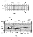
Figure 3 is a top view of a tooling system, according to the preferred embodiment of the present application; -
Figure 4 is a cross-sectional view of the tooling system, taken at section lines IV-IV, according to the preferred embodiment of the present application; -
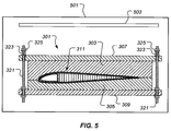
Figure 5 is schematic view of a the tooling system in an oven, according to the preferred embodiment of the present application; and -
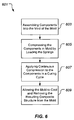
Figure 6 is a diagram of a method of manufacturing a composite structure, according to the preferred embodiment of the present application. - Illustrative embodiments of the system and method of the present application are described below. In the interest of clarity, not all features of an actual implementation are described in this specification. It will of course be appreciated that in the development of any such actual embodiment, numerous implementation-specific decisions must be made to achieve the developer's specific goals, such as compliance with system-related and business-related constraints, which will vary from one implementation to another. Moreover, it will be appreciated that such a development effort might be complex and time-consuming but would nevertheless be a routine undertaking for those of ordinary skill in the art having the benefit of this disclosure.
- In the specification, reference may be made to the spatial relationships between various components and to the spatial orientation of various aspects of components as the devices are depicted in the attached drawings. However, as will be recognized by those skilled in the art after a complete reading of the present application, the devices, members, apparatuses, etc. described herein may be positioned in any desired orientation. Thus, the use of terms such as "above," "bellow," "upper," "lower," or other like terms to describe a spatial relationship between various components or to describe the spatial orientation of aspects of such components should be understood to describe a relative relationship between the components or a spatial orientation of aspects of such components, respectively, as the device described herein may be oriented in any desired direction.
- Referring to
Figure 1 in the drawings, arotorcraft 101 is illustrated. Rotorcraft 101 has arotor system 103 with a plurality ofrotor blades 111. The pitch of eachrotor blade 111 can be selectively controlled in order to selectively control direction, thrust, and lift ofrotorcraft 101. Rotorcraft 101 further includes afuselage 105,landing gear 107, and anempennage 109. - Referring to
Figure 2 in the drawings, atiltrotor aircraft 201 is illustrated. Tiltrotoraircraft 201 includes afuselage 207, alanding gear 209, awing 209, androtatable nacelles nacelle rotor blades 211. The position ofnacelles rotor blades 211, can be selectively controlled in order to selectively control direction, thrust, and lift oftiltrotor aircraft 201. - It is especially desirable for components of rotorcraft 101 and
tiltrotor aircraft 201 to be manufactured with composite systems since composite components are typically very weight efficient. Illustrative composite components can include: wings, blades, spars, rotor grips, compartments, flooring, to name a few. As such, the system and method of the present application may be utilized to manufacture composite components for rotorcraft 101 andtiltrotor aircraft 201, as well as other aircraft. - The system and method of the present application can be utilized to manufacturing composite structures in a closed cavity mold. Conventional closed cavity mold manufacturing methods have significant limitations and shortcomings. For example, curing a composite structure in a closed cavity mold with ambient temperature and pressure typically results in poor cross-link density, high porosity, and substantial part variation. Further, relying upon an autoclave for both temperature and pressure is limiting, expensive, resource-consuming. Further, curing a composite structure in a closed cavity mold with a hydraulic press to create pressure has temperature constraints, lacks portability, and is undesirably expensive. Further, conventional clamping of a closed cavity mold can promote the formation of voids and porosity, and further lack the ability to accurately generate extreme contours in the composite structure. However, the system and method of the present application is configured to provide a substantially constant pressure to a composite structure during the curing cycle, thereby substantially preventing the formation of voids, while also more accurately generating contour profiles of the composite structure. Further, the system and method of the present application is particularly well suited for heating of the composite structure during the curing cycle by a wide variety of heating configurations. These and other advantages of the system and method of the present application are discussed further herein.
- It should be appreciated that the system and method of the present application may be utilized to manufacture composite components on other types of aircraft, as well as non-aircraft applications. For example, the system and method of the present application may be utilized to manufacture composite components on a wind turbine, space vehicle, ground vehicle, surface marine vehicle, amphibious marine vehicle, and submersible marine vehicle, to name a few examples.
- Referring to
Figures 3 and 4 , a springbiased tooling system 301, according to the preferred embodiment is illustrated.Tooling system 301 includes anupper mold 303 and alower mold 305. The interior surfaces ofupper mold 303 andlower mold 305 collectively form a void having the desired an outer mold line geometry of acomposite structure 311 being molded by thetooling system 301. In the illustrated embodiment, thecomposite structure 311 is a rotor blade, such asrotor blade 211 depicted inFigure 2 . The illustratedcomposite structure 311 includes anupper skin 313, alower skin 315, aspar 317, and acore 319 that are bonded together during a curing process. It should be appreciated that the illustrated rotor blade is merely exemplary of a wide range of composite structures that can be formed bytooling system 301. -
Tooling system 301 further includes a plurality ofupper adapters 307 andlower adapters 309. Eachupper adapter 307 andlower adapter 309 is a rigid member configured to transfer compressive forces generated by a plurality ofsprings 323 toupper mold 303 andlower mold 305.Tooling system 301 further includes a plurality ofrods 321, eachrod 321 being coupled tolower adapter 309 with nuts 327a and 327b. Eachspring 323 is located between an upper surface ofupper mold 303 and anut 325.Rod 321 is preferably threaded such thatnut 325 can be threaded ontorod 321 to an implementation specific torque and depth. One or more washers can be used to provide bearing surfaces betweennut 325 andspring 323, as well as betweenspring 323 andupper adapter 307. Furthermore, one or more washers can be used betweenlower adapter 309 and nuts 327a, 327b. - Compression derived from
springs 323 provides substantially constant pressure tocomposite structure 311 during resin shrinkage and mold settling that can occur during the curing cycle, thereby preventing the development of voids and porosity incomposite structure 311. Components oftooling system 301 can be installed exterior toupper mold 303 andlower mold 305, thereby makingtooling system 301 conveniently retrofitable onto existing closed cavity tooling. In the preferred embodiment, eachspring 323 is a die-spring having the capability to produce approximately 8007 Newtons (1800 pounds-force); however, it should be fully appreciated that the exact size and force producing capability ofsprings 323 is implementation specific. Further, eachnut 325 can be selectively torqued to provide the desired amount of compression ofupper mold 303 andlower mold 305. - One unique advantage of
tooling system 301 withsprings 323 to provide compression ofupper mold 303 andlower mold 305 is that thetooling system 301 is capable of withstanding and tolerating a variety of heating environments. Referring now also toFigure 5 , anoven 501 with aheating element 503 is illustrated.Oven 501 is one exemplary heating environment for whichtooling system 301 is particularly well suited for. In contrast, conventional methods of compressing a closed cavity tool, such as a hydraulic system, are highly susceptible to leakage when subjected to heat withinoven 501. Heat generated withinoven 501 promotes viscous flow and subsequent curing of resin and/or adhesive withincomposite structure 311. It should be fully appreciated that it is contemplated that other heating system and methods maybe used during the curing cycle. For example, heating blankets, radiant heat systems, and other non-pressurized heating systems can be used in lieu ofoven 501. Furthermore, an autoclave can be used; however,tooling system 301 is particularly well suited for using non-pressurized heating system that avoids the limitations and expense associated with curing in an autoclave. Further,composite structure 311 can employ a resin system that uses a catalyst, such as heat, ultraviolet rays (UV), to kick-off a reaction that results in the viscous changes and subsequent curing of the resin. Further,composite structure 311 can employ a thermal decomposition resin system that similarly uses a catalyst to kick-off a chemical reaction during the curing cycle. - Referring now also to
Figure 6 , amethod 601 for manufacturing a composite structure in springbiased tooling system 301 is schematically illustrated.Method 601 includes astep 603 for assembling components ofcomposite structure 311 into the void formed byupper mold 303 andlower mold 305. The components can include non-composite components, such as a metal component, as well as composite components. The composite components ofcomposite structure 311 can include any variety of uncured and cured components formed with any variety of composite fiber/resin systems. For example, an uncured composite component can be a preform of "pre-preg" composite strips which include one or more layers of fibers pre-impregnated with an uncured resin system. Furthermore, an adhesive or other resinous material can be used as a bonding agent between components within the void formed byupper mold 303 andlower mold 305. -
Method 601 further includes astep 605, which involves compressing the components within the void formed byupper mold 303 andlower mold 305. In the preferred embodiment, springs 323 perform the function of compressingupper mold 303 andlower mold 305 together. Eachspring 323 is compressed by anut 325. The compressive force of each spring is selectively controlled by selectively torque each nut to a desired torque level. For example, in the illustrated embodiment, eachnut 325 is torqued to approximately 176 Newton metres (130 foot-pounds); however, it should be appreciated that the exact torque level of eachnut 325 is implementation specific. -
Method 601 further includes astep 607, which involves applying continuous compression to the components within theupper mold 303 andlower mold 305 during a curing cycle. In the preferred embodiment, the curing cycle involves subjecting the components to heat and pressure for a designated amount of time. In an alternative embodiment, the curing cycle does not include actively applying heat, rather the curing cycle involves curing at ambient temperature. In the preferred embodiment, the pressure is created bysprings 323, while the heat is generated by an oven. As discussed further herein, the heat can be generated by any variety of sources. During the curing cycle, the resinous material, such as an adhesive, impregnated resin, or the like, becomes viscous allowing the pressure created bysprings 323 to compress and compact the components. As the components compress, springs 323 provide the critical function of continually applying pressure throughout the curing process to prevent the formation of voids, or other defect that may result from lack of pressure. More specifically, asupper mold 303 andlower mold 305 settle and move together, springs 323 extend to take-up distance so that pressure is maintained. Further, not only doessprings 323 provide and maintain pressure to the components to prevent formation of voids, but also ensure proper pressurized contact with the inner surfaces of the molds, so that the resultantcomposite structure 311 has the desired outer mold line geometry and contour. -
Method 601 further includes astep 609, which involves allowing the mold to cool and removing the resulting composite structure from the mold. After the curing of the components instep 607, a resulting composite structure is formed. However, the mold and composite structure are allowed to return to ambient temperature prior to disassembly. - The system and method of the present application provide significant advantages over conventional composite manufacturing practices. For example, the system and method of the present application provide for springs to apply substantially constant clamping pressure to the composite assembly during the curing cycle, without having to rely upon a hydraulic press, autoclave, or the like. Further, the system and method can reduce the capital expense that may otherwise be required for a conventional tooling and process. Further, the system and method compensate for mold settling and resin shrinkage that may otherwise result in a pressure loss during the curing cycle, thereby preventing development of voids and porosity in the cured composite structure. Further, the system and method produce composite structures that more closely match the desired shape, such as rotor blade twist and contour. Further, the system and method are particularly well suited for curing in an ambient pressure environment, thereby avoiding the expense and location restrictions associated with relying on an autoclave for application of pressure. Further, the system and method permit the transport of the tooling system to alternative facilities since presses and autoclaves, which are cumbersome to transport, are not required. Further, the system and method allow for pressure to be supplied by springs in an ambient pressure environment, as such, ambient pressure changes due to weather and location are dominated by the pressure generated by the springs, thereby producing parts that do not vary with changes in ambient pressure.
- The particular embodiments disclosed above are illustrative only, as the application may be modified and practiced in different but equivalent manners apparent to those skilled in the art having the benefit of the teachings herein. Furthermore, no limitations are intended to the details of construction or design herein shown, other than as described in the claims below. It is therefore evident that the particular embodiments disclosed above may be altered or modified and all such variations are considered within the scope and spirit of the application. Accordingly, the protection sought herein is as set forth in the claims below. It is apparent that a system with significant advantages has been described and illustrated. Although the system of the present application is shown in a limited number of forms, it is not limited to just these forms, but is amenable to various changes and modifications without departing from the spirit thereof.
Claims (13)
- A tooling system (301) for manufacturing a composite structure (311), the tooling system comprising:an upper mold (303) and a lower mold (305), the upper mold and the lower mold collectively forming a void, the void being configured to accept a preform;a plurality of spring members (323) configured to apply a substantially constant pressure to the preform during a curing cycle;a plurality of upper adapters (307) adjacent to the upper mold and a plurality of lower adapters (309) adjacent to the lower mold, each upper adapter (307) and lower adapter (309) being a rigid member configured to transfer compressive forces generated by the plurality of spring members (323) to the upper mold and the lower mold; anda plurality of rod members (321) coupled to the lower adapters (309);wherein each spring member is located between an upper surface of one of the upper adapters and a nut (325) screwed onto one of the rod members, the spring members and upper and lower adapters providing a constant pressure to the upper and lower mold during curing.
- The tooling system according to claim 1, wherein the rod members are threaded.
- The tooling system according to claim 1, wherein the void geometry has an outer mold line of a rotor blade.
- The tooling system according to claim 1, wherein the pressure generated by the spring members (323) is selectively controllable by selectively applying a torque to the nuts.
- The tooling system according to claim 1, further comprising:an oven (501) configured to apply a heat during a curing cycle, the oven being non-pressurized.
- The tooling system according to claim 1, wherein the spring members (323) are configured to apply the substantially constant pressure to the preform during the curing cycle, even when the preform compacts during the curing cycle.
- The tooling system according to any preceding claim, wherein each spring member is capable of producing approximately 8007 Newtons (1800 pounds-force) in compression.
- A method of manufacturing a composite part using a tooling system as claimed in any one of claims 1 to 7, the method comprising:assembling a preform (311) in the void formed by the upper mold (303) and the lower mold (305);applying a pressure to the preform by compressing the plurality of spring members (323) using the plurality of upper adaptors (307) adjacent to the upper mold (303), the plurality of lower adapters (309) adjacent to the lower mold (305), the plurality of rod members coupled to the lower adapters, and the plurality of nuts screwed onto the rod members; andcuring the preform until the preform becomes a cured composite structure.
- The method according the claim 8, further comprising:during the step of curing the preform, using forces from the plurality of spring members to compensate for mold settling and resin shrinkage that may otherwise result in a loss of pressure to the preform, thereby preventing development of voids and porosity in the cured composite structure
- The method according the claim 8 or claim 9, wherein the step of curing the preform includes applying heat to the preform.
- The method according the claim 10, wherein the heat is produced by one of:a non-pressurized oven (501);a heating blanket; anda radiant heat system.
- The method according the claim 9 or of claim 10 or claim 11, wherein the preform includes uncured composite components and cured composite components, or
wherein the preform includes cured composite components and uncured adhesive. - The method according the claim 9 or of claim 10 or claim 11 or claim 12, wherein the preform includes non-composite components.
Applications Claiming Priority (1)
| Application Number | Priority Date | Filing Date | Title |
|---|---|---|---|
| US13/404,111 US9381679B2 (en) | 2012-02-24 | 2012-02-24 | System and method of manufacturing a composite structure in a closed cavity mold |
Publications (3)
| Publication Number | Publication Date |
|---|---|
| EP2631052A2 EP2631052A2 (en) | 2013-08-28 |
| EP2631052A3 EP2631052A3 (en) | 2014-04-30 |
| EP2631052B1 true EP2631052B1 (en) | 2016-05-11 |
Family
ID=45976737
Family Applications (1)
| Application Number | Title | Priority Date | Filing Date |
|---|---|---|---|
| EP12161919.1A Not-in-force EP2631052B1 (en) | 2012-02-24 | 2012-03-28 | System and method of manufacturing a composite structure in a closed cavity mold |
Country Status (4)
| Country | Link |
|---|---|
| US (2) | US9381679B2 (en) |
| EP (1) | EP2631052B1 (en) |
| CN (1) | CN103286961B (en) |
| CA (1) | CA2805074C (en) |
Families Citing this family (10)
| Publication number | Priority date | Publication date | Assignee | Title |
|---|---|---|---|---|
| US9638048B2 (en) | 2013-03-15 | 2017-05-02 | Bell Helicopter Textron Inc. | Systems and methods of constructing composite assemblies |
| CN104552692B (en) * | 2013-10-28 | 2017-06-13 | 湖北航天化学技术研究所 | A kind of middle-size and small-size solid propellant rocket internal insulation bulge forming frock |
| GB2546925B (en) * | 2014-10-09 | 2021-01-13 | Synaptive Medical Barbados Inc | Phantom production tool |
| US10507600B2 (en) | 2015-09-14 | 2019-12-17 | Bell Helicopter Textron Inc. | Modular tooling for manufacturing multi-cavity composite structures |
| CN106273551B (en) * | 2016-10-13 | 2018-08-14 | 西北工业大学 | Shape Memory Alloy Fibers enhance composite material RTM and are integrally formed equipment |
| CN108188259B (en) * | 2017-12-30 | 2023-11-10 | 连云港神鹰碳纤维自行车有限公司 | Forming die and forming method for mounting hole for preventing yarn clamping |
| US11066188B2 (en) | 2018-08-10 | 2021-07-20 | Sikorsky Aircraft Corporation | Method and apparatus for locating and forming fastener holes in a replacement tip section of a rotor blade |
| US11242140B2 (en) | 2018-08-10 | 2022-02-08 | Sikorsky Aircraft Corporation | Method of removal and replacement of a tip section of a rotor blade |
| CN117584498A (en) * | 2023-11-08 | 2024-02-23 | 航天特种材料及工艺技术研究所 | A molding device and method suitable for adaptive pressurization of composite airfoils |
| CN119682263A (en) * | 2025-02-26 | 2025-03-25 | 北京玻钢院复合材料有限公司 | Composite material plate molding method and mold using disc automatic pressurization |
Family Cites Families (14)
| Publication number | Priority date | Publication date | Assignee | Title |
|---|---|---|---|---|
| US1004820A (en) * | 1909-04-29 | 1911-10-03 | Remy Electric Co | Vulcanizing apparatus. |
| US1451541A (en) * | 1919-05-15 | 1923-04-10 | Westinghouse Electric & Mfg Co | Method of and apparatus for making propellers |
| US1833009A (en) * | 1927-03-30 | 1931-11-24 | Schraders Son Inc | Vulcanizing apparatus |
| US2458864A (en) * | 1945-01-01 | 1949-01-11 | John D Lindsay | Method of making integral molded structures |
| FR926596A (en) | 1946-03-04 | 1947-10-06 | Alpha Soc | Locking system mold with pressure reserve |
| FR939646A (en) | 1947-01-10 | 1948-11-19 | Flange for mittens | |
| DE824677C (en) | 1950-02-04 | 1951-12-13 | Friedrich W Riederich | Adjustable device for elastic pressing and polymerizing of plastic for dental purposes |
| FR1090006A (en) | 1953-07-23 | 1955-03-25 | Citroen Sa Andre | Molding process |
| US3167129A (en) * | 1962-05-16 | 1965-01-26 | Enstrom Corp | Construction of airfoils having elastically-bent afterbodies |
| US3611506A (en) | 1969-04-30 | 1971-10-12 | Harry C Schroeder | Centrifugal casting spider and mold mounting thereon |
| GB1323470A (en) | 1969-10-24 | 1973-07-18 | Unilan Ag | Moulds |
| US4701293A (en) | 1985-09-24 | 1987-10-20 | Grumman Aerospace Corporation | Molding process and apparatus utilizing memory metal alloy springs |
| US4961700A (en) | 1988-12-15 | 1990-10-09 | Owens-Corning Fiberglas Corporation | Shaping means for the production of fiber-reinforced preform articles |
| DE4033438C1 (en) | 1990-10-20 | 1992-05-14 | Saar-Federn Gmbh, 6620 Voelklingen, De |
-
2012
- 2012-02-24 US US13/404,111 patent/US9381679B2/en active Active
- 2012-03-28 EP EP12161919.1A patent/EP2631052B1/en not_active Not-in-force
-
2013
- 2013-01-24 CN CN201310026389.2A patent/CN103286961B/en not_active Expired - Fee Related
- 2013-02-08 CA CA2805074A patent/CA2805074C/en active Active
-
2016
- 2016-06-29 US US15/196,650 patent/US9539772B2/en not_active Expired - Fee Related
Also Published As
| Publication number | Publication date |
|---|---|
| US20130221580A1 (en) | 2013-08-29 |
| CA2805074A1 (en) | 2013-08-24 |
| US20160303809A1 (en) | 2016-10-20 |
| CN103286961B (en) | 2017-05-31 |
| CN103286961A (en) | 2013-09-11 |
| CA2805074C (en) | 2015-11-24 |
| US9539772B2 (en) | 2017-01-10 |
| US9381679B2 (en) | 2016-07-05 |
| EP2631052A3 (en) | 2014-04-30 |
| EP2631052A2 (en) | 2013-08-28 |
Similar Documents
| Publication | Publication Date | Title |
|---|---|---|
| CA2805074C (en) | System and method of manufacturing a composite structure in a closed cavity mold | |
| US8043554B2 (en) | Manufacturing process using bladderless mold line conformal hat stringer | |
| US9669581B2 (en) | Method for manufacturing an aeronautical torsion box, torsion box and tool for manufacturing an aeronautical torsion box | |
| US5683646A (en) | Fabrication of large hollow composite structure with precisely defined outer surface | |
| US11400620B2 (en) | Methods and apparatus for curing composite nacelle structure | |
| US20080302912A1 (en) | Bladderless Mold Line Conformal Hat Stringer | |
| US20090297358A1 (en) | Modified blade stiffener and fabrication method therefor | |
| CN112238551A (en) | Multi-part integrated forming assembly die and forming assembly method for composite wing | |
| US11628601B2 (en) | Mold tools with anisotropic thermal properties and aligned carbon-reinforced thermoplastic fibres | |
| US7858012B2 (en) | Automated prototyping of a composite airframe | |
| CN106864769A (en) | Composite aircraft manufacturing tools and methods using articulated mandrels | |
| US11738493B2 (en) | Method of manufacturing an assembly fixture and a composite product | |
| US20240217645A1 (en) | Main body of an aerial vehicle | |
| EP2511082B1 (en) | Method for manufacturing products made of composite material with a closed-section sandwich structure | |
| CN117002039A (en) | A molding method for a composite material frame used to support attitude control engines | |
| CN117584498A (en) | A molding device and method suitable for adaptive pressurization of composite airfoils |
Legal Events
| Date | Code | Title | Description |
|---|---|---|---|
| PUAI | Public reference made under article 153(3) epc to a published international application that has entered the european phase |
Free format text: ORIGINAL CODE: 0009012 |
|
| 17P | Request for examination filed |
Effective date: 20120329 |
|
| AK | Designated contracting states |
Kind code of ref document: A2 Designated state(s): AL AT BE BG CH CY CZ DE DK EE ES FI FR GB GR HR HU IE IS IT LI LT LU LV MC MK MT NL NO PL PT RO RS SE SI SK SM TR |
|
| AX | Request for extension of the european patent |
Extension state: BA ME |
|
| PUAL | Search report despatched |
Free format text: ORIGINAL CODE: 0009013 |
|
| AK | Designated contracting states |
Kind code of ref document: A3 Designated state(s): AL AT BE BG CH CY CZ DE DK EE ES FI FR GB GR HR HU IE IS IT LI LT LU LV MC MK MT NL NO PL PT RO RS SE SI SK SM TR |
|
| AX | Request for extension of the european patent |
Extension state: BA ME |
|
| RIC1 | Information provided on ipc code assigned before grant |
Ipc: B29C 33/20 20060101AFI20140327BHEP Ipc: B29C 70/46 20060101ALN20140327BHEP Ipc: B29C 35/02 20060101ALN20140327BHEP |
|
| 17Q | First examination report despatched |
Effective date: 20141022 |
|
| GRAP | Despatch of communication of intention to grant a patent |
Free format text: ORIGINAL CODE: EPIDOSNIGR1 |
|
| RIC1 | Information provided on ipc code assigned before grant |
Ipc: B29C 33/20 20060101AFI20160108BHEP Ipc: B29C 35/02 20060101ALN20160108BHEP Ipc: B29C 70/46 20060101ALN20160108BHEP |
|
| GRAS | Grant fee paid |
Free format text: ORIGINAL CODE: EPIDOSNIGR3 |
|
| INTG | Intention to grant announced |
Effective date: 20160204 |
|
| GRAA | (expected) grant |
Free format text: ORIGINAL CODE: 0009210 |
|
| AK | Designated contracting states |
Kind code of ref document: B1 Designated state(s): AL AT BE BG CH CY CZ DE DK EE ES FI FR GB GR HR HU IE IS IT LI LT LU LV MC MK MT NL NO PL PT RO RS SE SI SK SM TR |
|
| REG | Reference to a national code |
Ref country code: GB Ref legal event code: FG4D |
|
| REG | Reference to a national code |
Ref country code: CH Ref legal event code: EP |
|
| REG | Reference to a national code |
Ref country code: AT Ref legal event code: REF Ref document number: 798286 Country of ref document: AT Kind code of ref document: T Effective date: 20160515 |
|
| REG | Reference to a national code |
Ref country code: IE Ref legal event code: FG4D |
|
| REG | Reference to a national code |
Ref country code: DE Ref legal event code: R096 Ref document number: 602012018263 Country of ref document: DE |
|
| REG | Reference to a national code |
Ref country code: LT Ref legal event code: MG4D |
|
| REG | Reference to a national code |
Ref country code: NL Ref legal event code: MP Effective date: 20160511 |
|
| PG25 | Lapsed in a contracting state [announced via postgrant information from national office to epo] |
Ref country code: NO Free format text: LAPSE BECAUSE OF FAILURE TO SUBMIT A TRANSLATION OF THE DESCRIPTION OR TO PAY THE FEE WITHIN THE PRESCRIBED TIME-LIMIT Effective date: 20160811 Ref country code: NL Free format text: LAPSE BECAUSE OF FAILURE TO SUBMIT A TRANSLATION OF THE DESCRIPTION OR TO PAY THE FEE WITHIN THE PRESCRIBED TIME-LIMIT Effective date: 20160511 Ref country code: FI Free format text: LAPSE BECAUSE OF FAILURE TO SUBMIT A TRANSLATION OF THE DESCRIPTION OR TO PAY THE FEE WITHIN THE PRESCRIBED TIME-LIMIT Effective date: 20160511 Ref country code: LT Free format text: LAPSE BECAUSE OF FAILURE TO SUBMIT A TRANSLATION OF THE DESCRIPTION OR TO PAY THE FEE WITHIN THE PRESCRIBED TIME-LIMIT Effective date: 20160511 |
|
| REG | Reference to a national code |
Ref country code: AT Ref legal event code: MK05 Ref document number: 798286 Country of ref document: AT Kind code of ref document: T Effective date: 20160511 |
|
| PG25 | Lapsed in a contracting state [announced via postgrant information from national office to epo] |
Ref country code: RS Free format text: LAPSE BECAUSE OF FAILURE TO SUBMIT A TRANSLATION OF THE DESCRIPTION OR TO PAY THE FEE WITHIN THE PRESCRIBED TIME-LIMIT Effective date: 20160511 Ref country code: HR Free format text: LAPSE BECAUSE OF FAILURE TO SUBMIT A TRANSLATION OF THE DESCRIPTION OR TO PAY THE FEE WITHIN THE PRESCRIBED TIME-LIMIT Effective date: 20160511 Ref country code: ES Free format text: LAPSE BECAUSE OF FAILURE TO SUBMIT A TRANSLATION OF THE DESCRIPTION OR TO PAY THE FEE WITHIN THE PRESCRIBED TIME-LIMIT Effective date: 20160511 Ref country code: LV Free format text: LAPSE BECAUSE OF FAILURE TO SUBMIT A TRANSLATION OF THE DESCRIPTION OR TO PAY THE FEE WITHIN THE PRESCRIBED TIME-LIMIT Effective date: 20160511 Ref country code: GR Free format text: LAPSE BECAUSE OF FAILURE TO SUBMIT A TRANSLATION OF THE DESCRIPTION OR TO PAY THE FEE WITHIN THE PRESCRIBED TIME-LIMIT Effective date: 20160812 Ref country code: SE Free format text: LAPSE BECAUSE OF FAILURE TO SUBMIT A TRANSLATION OF THE DESCRIPTION OR TO PAY THE FEE WITHIN THE PRESCRIBED TIME-LIMIT Effective date: 20160511 Ref country code: PT Free format text: LAPSE BECAUSE OF FAILURE TO SUBMIT A TRANSLATION OF THE DESCRIPTION OR TO PAY THE FEE WITHIN THE PRESCRIBED TIME-LIMIT Effective date: 20160912 |
|
| PG25 | Lapsed in a contracting state [announced via postgrant information from national office to epo] |
Ref country code: DK Free format text: LAPSE BECAUSE OF FAILURE TO SUBMIT A TRANSLATION OF THE DESCRIPTION OR TO PAY THE FEE WITHIN THE PRESCRIBED TIME-LIMIT Effective date: 20160511 Ref country code: RO Free format text: LAPSE BECAUSE OF FAILURE TO SUBMIT A TRANSLATION OF THE DESCRIPTION OR TO PAY THE FEE WITHIN THE PRESCRIBED TIME-LIMIT Effective date: 20160511 Ref country code: CZ Free format text: LAPSE BECAUSE OF FAILURE TO SUBMIT A TRANSLATION OF THE DESCRIPTION OR TO PAY THE FEE WITHIN THE PRESCRIBED TIME-LIMIT Effective date: 20160511 Ref country code: EE Free format text: LAPSE BECAUSE OF FAILURE TO SUBMIT A TRANSLATION OF THE DESCRIPTION OR TO PAY THE FEE WITHIN THE PRESCRIBED TIME-LIMIT Effective date: 20160511 Ref country code: SK Free format text: LAPSE BECAUSE OF FAILURE TO SUBMIT A TRANSLATION OF THE DESCRIPTION OR TO PAY THE FEE WITHIN THE PRESCRIBED TIME-LIMIT Effective date: 20160511 |
|
| REG | Reference to a national code |
Ref country code: DE Ref legal event code: R097 Ref document number: 602012018263 Country of ref document: DE |
|
| PG25 | Lapsed in a contracting state [announced via postgrant information from national office to epo] |
Ref country code: BE Free format text: LAPSE BECAUSE OF FAILURE TO SUBMIT A TRANSLATION OF THE DESCRIPTION OR TO PAY THE FEE WITHIN THE PRESCRIBED TIME-LIMIT Effective date: 20160511 Ref country code: PL Free format text: LAPSE BECAUSE OF FAILURE TO SUBMIT A TRANSLATION OF THE DESCRIPTION OR TO PAY THE FEE WITHIN THE PRESCRIBED TIME-LIMIT Effective date: 20160511 Ref country code: SM Free format text: LAPSE BECAUSE OF FAILURE TO SUBMIT A TRANSLATION OF THE DESCRIPTION OR TO PAY THE FEE WITHIN THE PRESCRIBED TIME-LIMIT Effective date: 20160511 Ref country code: AT Free format text: LAPSE BECAUSE OF FAILURE TO SUBMIT A TRANSLATION OF THE DESCRIPTION OR TO PAY THE FEE WITHIN THE PRESCRIBED TIME-LIMIT Effective date: 20160511 |
|
| PLBE | No opposition filed within time limit |
Free format text: ORIGINAL CODE: 0009261 |
|
| STAA | Information on the status of an ep patent application or granted ep patent |
Free format text: STATUS: NO OPPOSITION FILED WITHIN TIME LIMIT |
|
| REG | Reference to a national code |
Ref country code: FR Ref legal event code: PLFP Year of fee payment: 6 |
|
| 26N | No opposition filed |
Effective date: 20170214 |
|
| PG25 | Lapsed in a contracting state [announced via postgrant information from national office to epo] |
Ref country code: SI Free format text: LAPSE BECAUSE OF FAILURE TO SUBMIT A TRANSLATION OF THE DESCRIPTION OR TO PAY THE FEE WITHIN THE PRESCRIBED TIME-LIMIT Effective date: 20160511 |
|
| REG | Reference to a national code |
Ref country code: CH Ref legal event code: PL |
|
| PG25 | Lapsed in a contracting state [announced via postgrant information from national office to epo] |
Ref country code: MC Free format text: LAPSE BECAUSE OF FAILURE TO SUBMIT A TRANSLATION OF THE DESCRIPTION OR TO PAY THE FEE WITHIN THE PRESCRIBED TIME-LIMIT Effective date: 20160511 |
|
| REG | Reference to a national code |
Ref country code: IE Ref legal event code: MM4A |
|
| PG25 | Lapsed in a contracting state [announced via postgrant information from national office to epo] |
Ref country code: LU Free format text: LAPSE BECAUSE OF NON-PAYMENT OF DUE FEES Effective date: 20170328 |
|
| PG25 | Lapsed in a contracting state [announced via postgrant information from national office to epo] |
Ref country code: CH Free format text: LAPSE BECAUSE OF NON-PAYMENT OF DUE FEES Effective date: 20170331 Ref country code: LI Free format text: LAPSE BECAUSE OF NON-PAYMENT OF DUE FEES Effective date: 20170331 Ref country code: IE Free format text: LAPSE BECAUSE OF NON-PAYMENT OF DUE FEES Effective date: 20170328 |
|
| REG | Reference to a national code |
Ref country code: FR Ref legal event code: PLFP Year of fee payment: 7 |
|
| PG25 | Lapsed in a contracting state [announced via postgrant information from national office to epo] |
Ref country code: MT Free format text: LAPSE BECAUSE OF NON-PAYMENT OF DUE FEES Effective date: 20170328 |
|
| PG25 | Lapsed in a contracting state [announced via postgrant information from national office to epo] |
Ref country code: AL Free format text: LAPSE BECAUSE OF FAILURE TO SUBMIT A TRANSLATION OF THE DESCRIPTION OR TO PAY THE FEE WITHIN THE PRESCRIBED TIME-LIMIT Effective date: 20160511 |
|
| PG25 | Lapsed in a contracting state [announced via postgrant information from national office to epo] |
Ref country code: HU Free format text: LAPSE BECAUSE OF FAILURE TO SUBMIT A TRANSLATION OF THE DESCRIPTION OR TO PAY THE FEE WITHIN THE PRESCRIBED TIME-LIMIT; INVALID AB INITIO Effective date: 20120328 |
|
| PG25 | Lapsed in a contracting state [announced via postgrant information from national office to epo] |
Ref country code: BG Free format text: LAPSE BECAUSE OF FAILURE TO SUBMIT A TRANSLATION OF THE DESCRIPTION OR TO PAY THE FEE WITHIN THE PRESCRIBED TIME-LIMIT Effective date: 20160511 |
|
| PG25 | Lapsed in a contracting state [announced via postgrant information from national office to epo] |
Ref country code: CY Free format text: LAPSE BECAUSE OF NON-PAYMENT OF DUE FEES Effective date: 20160511 |
|
| PG25 | Lapsed in a contracting state [announced via postgrant information from national office to epo] |
Ref country code: MK Free format text: LAPSE BECAUSE OF FAILURE TO SUBMIT A TRANSLATION OF THE DESCRIPTION OR TO PAY THE FEE WITHIN THE PRESCRIBED TIME-LIMIT Effective date: 20160511 |
|
| PG25 | Lapsed in a contracting state [announced via postgrant information from national office to epo] |
Ref country code: TR Free format text: LAPSE BECAUSE OF FAILURE TO SUBMIT A TRANSLATION OF THE DESCRIPTION OR TO PAY THE FEE WITHIN THE PRESCRIBED TIME-LIMIT Effective date: 20160511 |
|
| PG25 | Lapsed in a contracting state [announced via postgrant information from national office to epo] |
Ref country code: IS Free format text: LAPSE BECAUSE OF FAILURE TO SUBMIT A TRANSLATION OF THE DESCRIPTION OR TO PAY THE FEE WITHIN THE PRESCRIBED TIME-LIMIT Effective date: 20160911 |
|
| PGFP | Annual fee paid to national office [announced via postgrant information from national office to epo] |
Ref country code: FR Payment date: 20230327 Year of fee payment: 12 |
|
| PGFP | Annual fee paid to national office [announced via postgrant information from national office to epo] |
Ref country code: IT Payment date: 20230321 Year of fee payment: 12 Ref country code: GB Payment date: 20230327 Year of fee payment: 12 Ref country code: DE Payment date: 20230329 Year of fee payment: 12 |
|
| P01 | Opt-out of the competence of the unified patent court (upc) registered |
Effective date: 20230602 |
|
| REG | Reference to a national code |
Ref country code: DE Ref legal event code: R119 Ref document number: 602012018263 Country of ref document: DE |
|
| GBPC | Gb: european patent ceased through non-payment of renewal fee |
Effective date: 20240328 |
|
| PG25 | Lapsed in a contracting state [announced via postgrant information from national office to epo] |
Ref country code: DE Free format text: LAPSE BECAUSE OF NON-PAYMENT OF DUE FEES Effective date: 20241001 |
|
| PG25 | Lapsed in a contracting state [announced via postgrant information from national office to epo] |
Ref country code: GB Free format text: LAPSE BECAUSE OF NON-PAYMENT OF DUE FEES Effective date: 20240328 |
|
| PG25 | Lapsed in a contracting state [announced via postgrant information from national office to epo] |
Ref country code: FR Free format text: LAPSE BECAUSE OF NON-PAYMENT OF DUE FEES Effective date: 20240331 |
|
| PG25 | Lapsed in a contracting state [announced via postgrant information from national office to epo] |
Ref country code: GB Free format text: LAPSE BECAUSE OF NON-PAYMENT OF DUE FEES Effective date: 20240328 Ref country code: FR Free format text: LAPSE BECAUSE OF NON-PAYMENT OF DUE FEES Effective date: 20240331 Ref country code: DE Free format text: LAPSE BECAUSE OF NON-PAYMENT OF DUE FEES Effective date: 20241001 |
|
| PG25 | Lapsed in a contracting state [announced via postgrant information from national office to epo] |
Ref country code: IT Free format text: LAPSE BECAUSE OF NON-PAYMENT OF DUE FEES Effective date: 20240328 |