EP2630080B1 - Method and apparatus for forming carbon dioxide particles into blocks - Google Patents
Method and apparatus for forming carbon dioxide particles into blocks Download PDFInfo
- Publication number
- EP2630080B1 EP2630080B1 EP11776673.3A EP11776673A EP2630080B1 EP 2630080 B1 EP2630080 B1 EP 2630080B1 EP 11776673 A EP11776673 A EP 11776673A EP 2630080 B1 EP2630080 B1 EP 2630080B1
- Authority
- EP
- European Patent Office
- Prior art keywords
- dosing
- forming chamber
- particles
- chamber
- volume
- Prior art date
- Legal status (The legal status is an assumption and is not a legal conclusion. Google has not performed a legal analysis and makes no representation as to the accuracy of the status listed.)
- Active
Links
Images














Classifications
-
- C—CHEMISTRY; METALLURGY
- C01—INORGANIC CHEMISTRY
- C01B—NON-METALLIC ELEMENTS; COMPOUNDS THEREOF; METALLOIDS OR COMPOUNDS THEREOF NOT COVERED BY SUBCLASS C01C
- C01B32/00—Carbon; Compounds thereof
- C01B32/50—Carbon dioxide
- C01B32/55—Solidifying
-
- B—PERFORMING OPERATIONS; TRANSPORTING
- B30—PRESSES
- B30B—PRESSES IN GENERAL
- B30B11/00—Presses specially adapted for forming shaped articles from material in particulate or plastic state, e.g. briquetting presses, tabletting presses
- B30B11/02—Presses specially adapted for forming shaped articles from material in particulate or plastic state, e.g. briquetting presses, tabletting presses using a ram exerting pressure on the material in a moulding space
- B30B11/025—Presses specially adapted for forming shaped articles from material in particulate or plastic state, e.g. briquetting presses, tabletting presses using a ram exerting pressure on the material in a moulding space whereby the material is transferred into the press chamber by relative movement between a ram and the press chamber
-
- B—PERFORMING OPERATIONS; TRANSPORTING
- B30—PRESSES
- B30B—PRESSES IN GENERAL
- B30B11/00—Presses specially adapted for forming shaped articles from material in particulate or plastic state, e.g. briquetting presses, tabletting presses
- B30B11/02—Presses specially adapted for forming shaped articles from material in particulate or plastic state, e.g. briquetting presses, tabletting presses using a ram exerting pressure on the material in a moulding space
- B30B11/04—Presses specially adapted for forming shaped articles from material in particulate or plastic state, e.g. briquetting presses, tabletting presses using a ram exerting pressure on the material in a moulding space co-operating with a fixed mould
-
- B—PERFORMING OPERATIONS; TRANSPORTING
- B30—PRESSES
- B30B—PRESSES IN GENERAL
- B30B15/00—Details of, or accessories for, presses; Auxiliary measures in connection with pressing
- B30B15/02—Dies; Inserts therefor; Mounting thereof; Moulds
- B30B15/022—Moulds for compacting material in powder, granular of pasta form
- B30B15/024—Moulds for compacting material in powder, granular of pasta form using elastic mould parts
-
- B—PERFORMING OPERATIONS; TRANSPORTING
- B30—PRESSES
- B30B—PRESSES IN GENERAL
- B30B15/00—Details of, or accessories for, presses; Auxiliary measures in connection with pressing
- B30B15/02—Dies; Inserts therefor; Mounting thereof; Moulds
- B30B15/026—Mounting of dies, platens or press rams
-
- B—PERFORMING OPERATIONS; TRANSPORTING
- B30—PRESSES
- B30B—PRESSES IN GENERAL
- B30B15/00—Details of, or accessories for, presses; Auxiliary measures in connection with pressing
- B30B15/30—Feeding material to presses
- B30B15/302—Feeding material in particulate or plastic state to moulding presses
- B30B15/304—Feeding material in particulate or plastic state to moulding presses by using feed frames or shoes with relative movement with regard to the mould or moulds
-
- B—PERFORMING OPERATIONS; TRANSPORTING
- B30—PRESSES
- B30B—PRESSES IN GENERAL
- B30B15/00—Details of, or accessories for, presses; Auxiliary measures in connection with pressing
- B30B15/32—Discharging presses
Definitions
- the present invention relates to forming solid blocks of a cryogenic material, and is particularly directed to a method and apparatus for forming carbon dioxide particles into blocks.
- Carbon dioxide has many uses in its various phases. Solid carbon dioxide has long been used to maintain items, such as food or beverages at desirable cool temperatures. In certain food service applications, solid blocks, or cakes, of carbon dioxide have been used, disposed within an given volume adjacent the items sought to be maintained at or below a desired temperature.
- the present invention provides a method and apparatus device for forming particles into blocks which produces accurately sized blocks and which allows the size of the blocks to be changed with minimal down time.
- the present invention will be described herein in connection with carbon dioxide, it will be understood that the present invention is not limited in use or application to carbon dioxide.
- US 6,244,069 B1 discloses an apparatus for producing carbon dioxide blocks having a formation unit which forms carbon dioxide blocks from carbon dioxide pellets conveyed to the formation unit.
- JP 2010 126407 relates to a method of compressing dry ice pellets in order to produce dry ice blocks, wherein the method comprises the step of spraying the dry ice pellets with water.
- US 2,151,855 relates to an apparatus for compressing carbon dioxide snow into blocks of dry ice.
- DE 37 31 769 A1 relates to a method of dosed filling a matrix-opening of a press-matrix with a granular material.
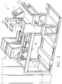
- Former 2 includes frame 4 which supports the former's components and includes an enclosure (not completely shown).
- former 2 includes two forming lines, generally indicated at 6 and 8, although former 2 may have one or more than two forming lines.
- former 2 includes conveyor assembly 10, human machine interface (HMI) 12 and enclosure 14 for housing power and control components.
- HMI human machine interface
- the hydraulic fluid supply system which provides a source of pressurized hydraulic fluid, preferably food grade, for the hydraulic cylinders of the former 2.
- the hydraulic fluid source may be carried by frame 4, such as in space 4a, or mounted remote to former 2.
- forming line 8 includes hopper 16 configured to receive particles, in this embodiment, carbon dioxide particles. In one embodiment, the lengths of the particles are less than about 0.5 inches.
- Vibrator 18 is carried by hopper 16. Any suitable device promote the flow of particles downwardly toward and out exit 16a of hopper 16 may be used. Exit 16a overlies dispensing tray 20, and includes door 16b to control the flow of particles from hopper 16 to tray 20. Dispensing tray 20 includes opening 20a (see also Fig. 4 ) which overlies dosing shuttle 22 and dosing cavity 24, with a small gap therebetween, about 0.5 to 1 inch.
- Forming line 8 also includes forming assembly 26, which will be discussed in more detail below.
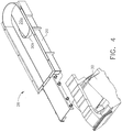
- dispensing assembly 28 is illustrated as comprising dispensing tray 20 which is mounted to vibrator 30 ( FIG. 4 illustrated tray 20 exploded from vibrator 30).
- Vibrator 30 is carried by frame 4, and functions to vibrate tray 20 so as to advance particles toward opening 20a.
- Vibrator 30 may be any of any suitable construction, such as may be well known. In the embodiment depicted, vibrator 30 was manufactured by Eriez.
- Tray 20 includes diverter 20b configured to direct particles there around so as to be introduced into dosing cavity 24 from the sides of opening 20a, to promote uniform distribution of particles in dosing cavity 24.
- Fig. 5 is a perspective view of an alternate vibrating tray embodiment, identified as 20', having a different shaped diverter 20'b.
- Fig. 5 illustrates a fragmentary support bracket 20'c for structural support to tray 20'.
- Dosing assembly 32 includes hydraulic cylinder 34 for reciprocating dosing shuttle 22 from a first position at which dosing cavity 24 is aligned with opening 20a so that dosing cavity 24 can be charged with particles, and a second position at which dosing cavity is aligned with forming chamber 38a so that forming chamber 38a can be charged with particles discharged from dosing cavity 24, and a third position at which dosing shuttle 22 has pushed a formed block onto the conveyor.
- Sensor 36 is positioned to sense when dosing shuttle 22 is in the charging position, and another sensor (not seen in Fig. 6 ) senses when dosing cavity 24 is aligned with forming chamber 38a.
- Dosing shuttle 22 may be made of any suitable material, such as UHMW.
- the amount particles dispensed into dosing cavity 24 is determined by the weight of the particles within dosing cavity 24.
- weighing system 40 can be seen comprising load cell 42 cantilevered at one end, and supporting and locating weighing platform 44 at distal end 42a.
- weighing platform 44 includes upper plate 46 made of stainless steel in the depicted embodiment.
- the lower surface of upper plate 46 includes cavities (not shown) into which a pair of heaters 48 extend.
- Each heater includes a downwardly depending projection 48a ( Fig.
- Thermocouple 52 is embedded in the bottom surface of upper plate 46. Ceramic heater 52 is also disposed adjacent or embedded into the lower surface of upper plate 46, disposed to prevent particles from freezing at that end of the weighing platform (it being noted that shuttle 22 moves relative to weighing platform 44.
- a pair of air knives 58 are disposed at the end of dosing assembly 32 adjacent the forming assembly 26, which are connected to a source of pressurized air, such as shop air, to reduce the chance of agglomerating particles at that location.
- the system controller stops the flow of particles into dosing cavity 42 by stopping the vibration of dispensing tray 20.
- the shuttle is controlled to charge forming chamber 38a.
- guide rails 56 guide dosing shuttle 22 so as to maintain the appropriate position relative to the other components.
- guide rails 56 are illustrated as having a combined rectangular and T cross section.
- Guide rails 56 may be of any suitable cross sectional shape and length so as to maintain dosing shuttle 22 in the appropriate position relative to the other components.
- Forming assembly 26 includes piston assembly 60, forming chamber block 38 and eject assembly 62.
- Piston assembly 60 includes press hydraulic cylinder 64 and press piston assembly 66 attached thereto.
- Press piston assembly includes press piston 68 which is attached to press piston block 70, disposed in the retracted position high enough to allow dosing shuttle 22 to travel between its first position and its second and third positions (described above).
- Press piston 68 may be made of any suitable material, such as UHMW.
- the lower relieved portion of press piston block 70 extends into a recess formed in the upper surface of press piston 68 such that the two components are secured together by fasteners.
- press piston 68 The orientation and location of press piston 68 is maintained by press piston guide 72. Press piston 68 is maintained in alignment with forming chamber 38a.
- the upper edges of forming chamber 38a are chamfered to provide a lead in for press piston 68 so that it can enter forming chamber 38a without interfering with the upper edges of forming chamber 38a, and proceed to compress carbon dioxide particles into blocks, as described below.
- Adequate clearance between press piston 66 and the walls of forming chamber 38a is provided, which in the embodiment depicted is about .020 to .030 inches on a side.
- Eject assembly 62 includes eject piston 74, formed of any suitable material such as UHMW and which is attached to eject piston block 76 in the same manner as press piston 68 and press piston block 70.
- Eject piston block 76 is mounted to eject piston mounting slide 78 which is releasably connected to eject hydraulic cylinder 80.
- Spacer 82 is disposed beneath eject piston mounting slide 78, supported vertically on its lower side, establishing the position of the upper surface 74a of eject piston 74 within forming chamber 38a.
- spacer 82 functions as the reaction member to the force exerted by press piston 68, through the carbon dioxide particles, through eject piston 74, and through eject piston block 76.
- lower eject hydraulic cylinder 80 does is not sized to oppose the force of press hydraulic cylinder 64, but only sized to lift eject piston 74 to eject a formed block.
- Figs. 14 and 14A illustrate front block 84 pivoted to its open position, allowing access to forming block 38 for removal, such as to exchange for another size block.
- Forming block 38 may be of any suitable dimension, such as 210 cm x 125 cm or 150 cm x 150 cm. The removal and installation of forming block 38 is described below.
- eject piston 74 and spacer 82 are illustrated removed from eject assembly 62.
- the upper end of eject hydraulic cylinder 80 carries mount 86 which is configured to slidably receive eject piston mounting slide 78. It is noted that the process for removing eject piston 74, as described below, involves locating eject piston 74 within forming chamber 38a and removing forming block 38 while eject piston 74 is disposed therein.
- Figs. 15 -19 illustrate the process for installing spacer 82.
- the thickness of spacer 82 sets the location of upper surface 74a of eject piston 74, which may be used, at least in certain embodiments, to control the volume of particle disposed into forming chamber 38a, such as when forming chamber 38a is filled completely to its upper edge, thereby controlling the thickness of the formed block.
- a metered dose is dispensed into dosing chamber 24, such as based on weight, forming chamber does not have to be filled to its upper edge to produce the desired thickness of the formed block.
- spacer 82 may be inserted into the space under eject piston mounting slide 78, with the space between spaced apart legs 82a, 82b receiving eject hydraulic cylinder rod 80a, as illustrated in Fig. 17 .
- spacer 82 is tilted down such that locating pads 82c, 82d (see Fig. 20 ) align with supports 88a, 88b, such that spacer 82 can be rotated down into its operational position as shown in Fig. 19 .
- pads 92c, 82d including perpendicular lips 82e, 82f at the edge of inclines 82g, 82h, locate spacer 82.
- Inclines 82g, 82h help to guide spacer 82 into and out of its operational position.
- press piston assembly 66 and press piston guide 72 are shown in a partially exploded view.
- Press piston guide 72 may be made of any suitable material, such as UHMW.
- press piston guide 72 is attached to metallic backing plate 72a, and mounted to leg 90 of forming assembly 26 via a T shaped mount (partially illustrated) or other suitable shape.
- Guide 72 may be held in place horizontally by detent 92.
- Press piston block 70 is mounted to press piston mounting slide, which includes mounting plate 96.
- Attached to the lower end of press hydraulic cylinder rod 64a is two piece mounting collar 98.
- Press mounting slide 94 includes two spaced apart parallel legs that slidably fit over collar 89, with end plate 96 being secured to collar 98b so as to retain press piston assembly 66 in its proper position.
- Figs. 23 - 25 illustrate the remaining design configuration of forming assembly 26 that permits quick change of forming block 38 and eject piston 74 to accompany the previously described configurations that allow the quick change of press piston assembly 66 press in as little as ten minutes or less to different perimeter dimensions for the formed block.
- Front block 84 is held in place by tapered pins 100 having hex nuts on their respective upper ends to allow rotation of tapered pins to facilitate removal along their axes by breaking any bond between the pins and the holes. Once removed, front block 84 may be rotated out of the way to allow forming block 38 to be withdrawn horizontally. Not shown in Figs.
- Forming block 38 includes flange 38b about its lower edge, which locates forming block within forming assembly 26.
- forming block 38 may be of any suitable size, shape and material.
- forming block 38 comprised end walls 38c, 38d, made of UHMW with side walls 38e and 38f made of stainless steel for dimensional stability and accuracy to avoid temperature gradient induced distortion in the side walls.
- Figs. 27 - 31 illustrate the process for forming blocks from carbon dioxide particles utilizing a volumetric embodiment of dosing shuttle, identified in these figures as 102. It will be understood that while the shuttle design and volumetric dosing described with regard to these figures is different from the weight based dosing described earlier, the steps of filling the forming chamber, advancing and retracting the press and eject pistons are applicable to the weight based dosing configuration.
- volumetric dosing shuttle 102 includes dosing cavity 104.
- dosing cavity 104 In the first position, as shown in Fig. 27 , dosing cavity 104 directly underlies hopper 106, having no door at the exit of hopper 106, such that particles freely flow into dosing cavity 104.
- upper surface 102a functions as a horizontal door at the exit of hopper 106, blocking an continuous flow of particles.
- eject piston 74 is extended fully up, with a formed block 108 thereon, having a vertical thickness of less than the vertical height of shuttle 102. The exact thickness of block 108 is controlled by the thickness of spacer 82.
- shuttle 102 is being advanced from its first position toward the third position, along guide rails 110, to push block 108 onto conveyor belt 112 by the outer distal edge 102b of shuttle 102, passing over UHMW plate 114.
- the exit of hopper 106 is illustrated blocked by upper surface 102a.
- Eject piston 74 remains at its upper most position, preventing particles from dropping out of cavity 104.
- Fig. 29 illustrates shuttle 102 in its fully extended, third position.
- volumetric dosing chamber 104 is larger than the volume of forming chamber as defined by the position of eject piston 74 when adjacent spacer 82. This ensures a complete, and therefore controlled and repeatable dosing and resultant block 108.
- trailing edge 104a of dosing cavity 104 of shuttle 102 is curved to direct pellets into the forming chamber, as shown in Fig. 32 .
- press piston 68 has advanced to its full extended position, compressing the particles within the forming chamber to the final block height.
- Press piston 68 is advanced from its retracted position at its full speed, until the hydraulic pressure of press hydraulic cylinder 64 reaches a predetermined level, at which the speed of press piston 68 is reduced.
- the speed of the press piston 68 as monitored by an appropriately placed linear transducer, such as on the hydraulic cylinder rod 64a, drops below a predetermined speed, or the speed profile approaches a predetermined shape, advance of the press piston 68 is stopped, press piston 68 is retracted, and eject piston 74 raised, returning the process to that as shown in Fig. 27 , to be repeated cyclically.
- conveyor assembly 10 is illustrated.
- Enclosure 112 overlies conveyor 110, with hinged door 114 along its longitudinal side (relative to discharge direction of conveyor 110).
- Door 114 is maintained in position by magnetic catch 116.
- Sensor 118 signals if door 114 is opened, and operation of former 2 is interrupted. This will happen for example if opened by a person during operation, presents a safety hazard. Also, if blocks 108 become jammed on conveyor 110, blocks will push door 114 open, interrupting operation.
- conveyor 110 is illustrated supported by a frame.
- Fig. 35 a detailed configuration of an embodiment of conveyor 110 is illustrated, showing individual rows 110a of UHMW links driven by sprocket 122.
- An alternate embodiment of a forming block and forming chamber may have a forming block with two chambers and matching two headed press and eject pistons.
Landscapes
- Engineering & Computer Science (AREA)
- Mechanical Engineering (AREA)
- Chemical & Material Sciences (AREA)
- Organic Chemistry (AREA)
- Chemical Kinetics & Catalysis (AREA)
- Inorganic Chemistry (AREA)
- Basic Packing Technique (AREA)
- Confectionery (AREA)
- Processing And Handling Of Plastics And Other Materials For Molding In General (AREA)
- Casting Or Compression Moulding Of Plastics Or The Like (AREA)
- Carbon And Carbon Compounds (AREA)
- Filling Or Emptying Of Bunkers, Hoppers, And Tanks (AREA)
Description
- The present invention relates to forming solid blocks of a cryogenic material, and is particularly directed to a method and apparatus for forming carbon dioxide particles into blocks.
- Carbon dioxide has many uses in its various phases. Solid carbon dioxide has long been used to maintain items, such as food or beverages at desirable cool temperatures. In certain food service applications, solid blocks, or cakes, of carbon dioxide have been used, disposed within an given volume adjacent the items sought to be maintained at or below a desired temperature.
- The airline industry is an example of this use of carbon dioxide blocks, wherein carbon dioxide blocks of a preselected size are disposed within one or more compartments of the food carts, thereby keeping the food served to air passengers at or below the desired temperature. In order to meet such need for carbon dioxide blocks, it is known to cut carbon dioxide blocks of the desired size from larger blocks as well as to form the desired sized blocks from carbon dioxide particles, There is a need for flexibility to be able to provide different sized blocks matched to the specific compartment sizes.
- The present invention provides a method and apparatus device for forming particles into blocks which produces accurately sized blocks and which allows the size of the blocks to be changed with minimal down time. Although the present invention will be described herein in connection with carbon dioxide, it will be understood that the present invention is not limited in use or application to carbon dioxide.
-
US 6,244,069 B1 discloses an apparatus for producing carbon dioxide blocks having a formation unit which forms carbon dioxide blocks from carbon dioxide pellets conveyed to the formation unit. -
JP 2010 126407 -
US 2,151,855 relates to an apparatus for compressing carbon dioxide snow into blocks of dry ice. -
DE 37 31 769 A1 relates to a method of dosed filling a matrix-opening of a press-matrix with a granular material. - The accompanying drawings, which are incorporated in and constitute a part of this specification, illustrate embodiments of the invention, and, together with the general description of the invention given above, and the detailed description of the embodiments given below, serve to explain the principles of the present invention.
-
FIG. 1 is a perspective view of a block former constructed in accordance with teachings of the present invention. -
FIG. 2 is a perspective view of the block former ofFig. 2 with certain components omitted for clarity. -
FIG. 3 is a side cross-sectional perspective view of the block former ofFig. 2 taken along the midline of one of the forming lines. -
FIG. 4 is perspective view of components of the vibrating tray assembly of the former ofFig. 1 . -
FIG. 5 is a perspective view of an alternate embodiment of the vibrating tray. -
FIG. 6 is a perspective view of the left dosing shuttle and forming assembly of the former ofFig. 1 . -
FIG. 7 is a side cross-sectional bottom perspective view of the dosing shuttle and forming assembly shown inFig. 6 . taken along the midline of the dosing shuttle and forming assembly. -
FIG. 8 is a side perspective view of the forming assembly ofFig. 6 , with an alternate embodiment of the weighing structure and the dosing shuttle omitted for clarity. -
FIG. 9 is a side perspective view showing the dosing shuttle assembly with the dosing shuttle hydraulic omitted for clarity. -
FIG. 10 is a side perspective view similar toFig. 9 with a shuttle guide and a lower plate omitted for clarity. -
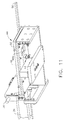
FIG. 11 is a bottom side perspective view of the dosing shuttle assembly shown inFig. 10 . -
FIG. 12 is a side perspective view similar toFig. 10 with the weighing plate omitted for clarity. -
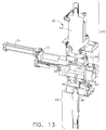
FIG. 13 is a cross-sectional top perspective view of the dosing shuttle and forming assembly similar toFig. 7 . -
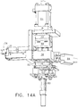
FIGS. 14 and14A are side perspective views of the dosing shuttle and forming assembly ofFig. 6 , with the front block pivoted to the open position. -
FIG. 15 is a front perspective view of the dosing shuttle and forming assembly ofFig. 6 with the ejection piston and spacer exploded out. -
FIGS. 16 is a front perspective view of the dosing shuttle and forming assembly ofFig. 6 , with the spacer oriented for insertion into the forming assembly. -
FIG. 17 is a front perspective view similar toFig. 16 , illustrating the spacer being installed under the ejection piston. -
FIG. 18 is a side view of the dosing shuttle and forming assembly ofFig. 6 , showing the spacer tilted during installation. -
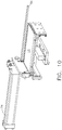
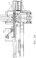
FIG. 19 is a side view of the dosing shuttle and forming assembly ofFig. 6 similar toFig. 18 , showing the spacer installed under the ejection piston. -
FIG. 20 is an enlarged bottom perspective view of the spacer. -
FIG. 21 is a front perspective view similar toFig. 17 , with the spacer installed under the ejection piston, showing the press piston assembly and press piston guide exploded out. -
FIG. 22 is a front perspective view similar toFig. 21 , showing the press guide installed. -
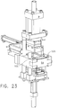
FIG. 23 is a front perspective view similar toFig. 21 , showing the press piston assembly and press piston guide installed. -
FIG. 24 is an front perspective view of the dosing shuttle and forming assembly, similar toFigs. 14 and14A , illustrating a step in the removal process of the forming chamber block and ejection piston. -
FIG. 25 is a front perspective view similar toFig. 24 , illustrating the forming chamber block and ejection piston removed (and with the press piston omitted). -
FIG. 26 is side perspective view of the forming chamber block with one side omitted for clarity. -
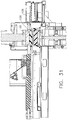
FIGS. 27 - 31 are side cross-sectional drawings illustrating the process of forming a block. -
FIG. 32 is a side cross-sectional view of the volumetric shuttle shown inFigs. 27-31 . -
FIG. 33 is a perspective view of the conveyor assembly shown inFIG. 1 . -
FIG. 34 is a perspective view of the conveyor belt assembly. -
FIG. 35 is an enlarged fragmentary view of.the conveyor belt engaged by a drive sprocket. - Reference will now be made in detail to the present preferred embodiment of the invention, an example of which is illustrated in the accompanying drawings.
- In the following description, like reference characters designate like or corresponding parts throughout the several views. Also, in the following description, it is to be understood that terms such as front, back, inside, outside, and the like are words of convenience and are not to be construed as limiting terms. Terminology used in this patent is not meant to be limiting insofar as devices described herein, or portions thereof, may be attached or utilized in other orientations. Referring in more detail to the drawings, an embodiment of the invention will now be described.
- Referring to
Figs. 1 and2 , there is shown an apparatus, indicated generally at 2 for forming carbon dioxide blocks, also referred to herein as a former or reformed. Former 2 includesframe 4 which supports the former's components and includes an enclosure (not completely shown). Former 2 includes two forming lines, generally indicated at 6 and 8, although former 2 may have one or more than two forming lines. Former 2 includesconveyor assembly 10, human machine interface (HMI) 12 andenclosure 14 for housing power and control components. Not illustrated is the hydraulic fluid supply system which provides a source of pressurized hydraulic fluid, preferably food grade, for the hydraulic cylinders of the former 2. The hydraulic fluid source may be carried byframe 4, such as in space 4a, or mounted remote to former 2. - Although the size of the components of both forming
lines line 8 will be discussed herein in detail. - Referring also to
Fig. 3 , formingline 8 includeshopper 16 configured to receive particles, in this embodiment, carbon dioxide particles. In one embodiment, the lengths of the particles are less than about 0.5 inches.Vibrator 18 is carried byhopper 16. Any suitable device promote the flow of particles downwardly toward and outexit 16a ofhopper 16 may be used.Exit 16a overlies dispensingtray 20, and includesdoor 16b to control the flow of particles fromhopper 16 totray 20. Dispensingtray 20 includesopening 20a (see alsoFig. 4 ) which overliesdosing shuttle 22 anddosing cavity 24, with a small gap therebetween, about 0.5 to 1 inch. - Forming
line 8 also includes formingassembly 26, which will be discussed in more detail below. - Referring to
Fig. 4 , dispensingassembly 28 is illustrated as comprising dispensingtray 20 which is mounted to vibrator 30 (Fig. 4 illustratedtray 20 exploded from vibrator 30).Vibrator 30 is carried byframe 4, and functions to vibratetray 20 so as to advance particles towardopening 20a.Vibrator 30 may be any of any suitable construction, such as may be well known. In the embodiment depicted,vibrator 30 was manufactured by Eriez.Tray 20 includesdiverter 20b configured to direct particles there around so as to be introduced intodosing cavity 24 from the sides ofopening 20a, to promote uniform distribution of particles indosing cavity 24. -
Fig. 5 is a perspective view of an alternate vibrating tray embodiment, identified as 20', having a different shaped diverter 20'b.Fig. 5 illustrates a fragmentary support bracket 20'c for structural support to tray 20'. - Referring to
Figs. 6 and7 ,dosing assembly 32 and formingassembly 26 of formingline 8 are shown.Dosing assembly 32 includeshydraulic cylinder 34 for reciprocatingdosing shuttle 22 from a first position at whichdosing cavity 24 is aligned withopening 20a so thatdosing cavity 24 can be charged with particles, and a second position at which dosing cavity is aligned with formingchamber 38a so that formingchamber 38a can be charged with particles discharged fromdosing cavity 24, and a third position at whichdosing shuttle 22 has pushed a formed block onto the conveyor.Sensor 36 is positioned to sense whendosing shuttle 22 is in the charging position, and another sensor (not seen inFig. 6 ) senses whendosing cavity 24 is aligned with formingchamber 38a.Dosing shuttle 22 may be made of any suitable material, such as UHMW. - In this embodiment depicted, the amount particles dispensed into
dosing cavity 24 is determined by the weight of the particles withindosing cavity 24. InFig. 7 , weighingsystem 40 can be seen comprisingload cell 42 cantilevered at one end, and supporting and locating weighingplatform 44 at distal end 42a. Referring also toFigs. 8 - 12a , which depict an alternate embodiment ofload cell 42', cantilevered from the lateral side instead of the longitudinal side, weighingplatform 44 includesupper plate 46 made of stainless steel in the depicted embodiment. The lower surface ofupper plate 46 includes cavities (not shown) into which a pair ofheaters 48 extend. Each heater includes a downwardly dependingprojection 48a (Fig. 12a ) that extending intoopenings 50a formed inintermediate plate 50 of weighingplatform 44.Thermocouple 52 is embedded in the bottom surface ofupper plate 46.Ceramic heater 52 is also disposed adjacent or embedded into the lower surface ofupper plate 46, disposed to prevent particles from freezing at that end of the weighing platform (it being noted thatshuttle 22 moves relative to weighingplatform 44. A pair ofair knives 58 are disposed at the end ofdosing assembly 32 adjacent the formingassembly 26, which are connected to a source of pressurized air, such as shop air, to reduce the chance of agglomerating particles at that location. - When the signal from
load cell 42 indicates the desired weight of particles are present withindosing cavity 42, the system controller stops the flow of particles intodosing cavity 42 by stopping the vibration of dispensingtray 20. When the desired weight of particles are present, the shuttle is controlled to charge formingchamber 38a. - As seen in
Fig. 9 , a pair of spaced apartguide rails 56 are supported by the dosing assembly.Guide rails 56guide dosing shuttle 22 so as to maintain the appropriate position relative to the other components. In the embodiment depicted,guide rails 56 are illustrated as having a combined rectangular and T cross section.Guide rails 56 may be of any suitable cross sectional shape and length so as to maintaindosing shuttle 22 in the appropriate position relative to the other components. - Included in
Figs. 6 ,8 and13 are illustrations of formingassembly 26. Formingassembly 26 includespiston assembly 60, formingchamber block 38 and ejectassembly 62.Piston assembly 60 includes presshydraulic cylinder 64 andpress piston assembly 66 attached thereto. Press piston assembly includespress piston 68 which is attached to presspiston block 70, disposed in the retracted position high enough to allowdosing shuttle 22 to travel between its first position and its second and third positions (described above).Press piston 68 may be made of any suitable material, such as UHMW. As can be seen in the cross-section ofFig. 13 , the lower relieved portion ofpress piston block 70 extends into a recess formed in the upper surface ofpress piston 68 such that the two components are secured together by fasteners. - The orientation and location of
press piston 68 is maintained bypress piston guide 72.Press piston 68 is maintained in alignment with formingchamber 38a. The upper edges of formingchamber 38a are chamfered to provide a lead in forpress piston 68 so that it can enter formingchamber 38a without interfering with the upper edges of formingchamber 38a, and proceed to compress carbon dioxide particles into blocks, as described below. Adequate clearance betweenpress piston 66 and the walls of formingchamber 38a is provided, which in the embodiment depicted is about .020 to .030 inches on a side. -
Eject assembly 62 includeseject piston 74, formed of any suitable material such as UHMW and which is attached to ejectpiston block 76 in the same manner aspress piston 68 andpress piston block 70.Eject piston block 76 is mounted to ejectpiston mounting slide 78 which is releasably connected to ejecthydraulic cylinder 80.Spacer 82 is disposed beneath ejectpiston mounting slide 78, supported vertically on its lower side, establishing the position of theupper surface 74a ofeject piston 74 within formingchamber 38a. During formation of blocks, as described below, spacer 82 functions as the reaction member to the force exerted bypress piston 68, through the carbon dioxide particles, througheject piston 74, and througheject piston block 76. With this construction, lower ejecthydraulic cylinder 80 does is not sized to oppose the force of presshydraulic cylinder 64, but only sized to lifteject piston 74 to eject a formed block. -
Figs. 14 and14A illustratefront block 84 pivoted to its open position, allowing access to formingblock 38 for removal, such as to exchange for another size block. Formingblock 38 may be of any suitable dimension, such as 210 cm x 125 cm or 150 cm x 150 cm. The removal and installation of formingblock 38 is described below. - Referring to
Fig. 15 ,eject piston 74 andspacer 82 are illustrated removed fromeject assembly 62. As seen inFig. 15 , the upper end of ejecthydraulic cylinder 80 carries mount 86 which is configured to slidably receive ejectpiston mounting slide 78. It is noted that the process for removingeject piston 74, as described below, involves locatingeject piston 74 within formingchamber 38a and removing formingblock 38 whileeject piston 74 is disposed therein. -
Figs. 15 -19 illustrate the process for installingspacer 82. The thickness ofspacer 82 sets the location ofupper surface 74a ofeject piston 74, which may be used, at least in certain embodiments, to control the volume of particle disposed into formingchamber 38a, such as when formingchamber 38a is filled completely to its upper edge, thereby controlling the thickness of the formed block. Of course, as described above, when a metered dose is dispensed intodosing chamber 24, such as based on weight, forming chamber does not have to be filled to its upper edge to produce the desired thickness of the formed block. - As illustrated by
Fig. 16 , with ejecthydraulic cylinder 80 extended such that ejectpiston mounting slide 78 is disposed high enough to allow insertion ofspacer 82,spacer 82 may be inserted into the space under ejectpiston mounting slide 78, with the space between spacedapart legs hydraulic cylinder rod 80a, as illustrated inFig. 17 . As it is inserted,spacer 82 is tilted down such that locatingpads Fig. 20 ) align withsupports spacer 82 can be rotated down into its operational position as shown inFig. 19 . The configuration ofpads 92c, 82d, includingperpendicular lips spacer 82. Inclines 82g, 82h, help to guidespacer 82 into and out of its operational position. - Referring to
Figs. 21 and22 ,press piston assembly 66 andpress piston guide 72 are shown in a partially exploded view. Press piston guide 72 may be made of any suitable material, such as UHMW. In the depicted embodiment,press piston guide 72 is attached tometallic backing plate 72a, and mounted toleg 90 of formingassembly 26 via a T shaped mount (partially illustrated) or other suitable shape.Guide 72 may be held in place horizontally bydetent 92.Press piston block 70 is mounted to press piston mounting slide, which includes mountingplate 96. Attached to the lower end of press hydraulic cylinder rod 64a is twopiece mounting collar 98. Press mountingslide 94 includes two spaced apart parallel legs that slidably fit over collar 89, withend plate 96 being secured tocollar 98b so as to retainpress piston assembly 66 in its proper position. -
Figs. 23 - 25 illustrate the remaining design configuration of formingassembly 26 that permits quick change of formingblock 38 and ejectpiston 74 to accompany the previously described configurations that allow the quick change ofpress piston assembly 66 press in as little as ten minutes or less to different perimeter dimensions for the formed block.Front block 84 is held in place bytapered pins 100 having hex nuts on their respective upper ends to allow rotation of tapered pins to facilitate removal along their axes by breaking any bond between the pins and the holes. Once removed,front block 84 may be rotated out of the way to allow formingblock 38 to be withdrawn horizontally. Not shown inFigs. 23 - 25 , ifeject piston 74 is to be removed, it is removed concomitantly with formingblock 38 while disposed in formingchamber 38a. Formingblock 38 includesflange 38b about its lower edge, which locates forming block within formingassembly 26. - Referring to
Fig. 26 , formingblock 38 may be of any suitable size, shape and material. In the embodiment depicted, formingblock 38 comprisedend walls side walls -
Figs. 27 - 31 illustrate the process for forming blocks from carbon dioxide particles utilizing a volumetric embodiment of dosing shuttle, identified in these figures as 102. It will be understood that while the shuttle design and volumetric dosing described with regard to these figures is different from the weight based dosing described earlier, the steps of filling the forming chamber, advancing and retracting the press and eject pistons are applicable to the weight based dosing configuration. - As seen in
Fig. 27 ,volumetric dosing shuttle 102 includesdosing cavity 104. In the first position, as shown inFig. 27 ,dosing cavity 104 directly underlieshopper 106, having no door at the exit ofhopper 106, such that particles freely flow intodosing cavity 104. Whenshuttle 102 is advanced to its second and third positions,upper surface 102a functions as a horizontal door at the exit ofhopper 106, blocking an continuous flow of particles. InFig. 27 ,eject piston 74 is extended fully up, with a formedblock 108 thereon, having a vertical thickness of less than the vertical height ofshuttle 102. The exact thickness ofblock 108 is controlled by the thickness ofspacer 82. - As seen in
Fig. 28 ,shuttle 102 is being advanced from its first position toward the third position, alongguide rails 110, to push block 108 ontoconveyor belt 112 by the outerdistal edge 102b ofshuttle 102, passing overUHMW plate 114. The exit ofhopper 106 is illustrated blocked byupper surface 102a.Eject piston 74 remains at its upper most position, preventing particles from dropping out ofcavity 104.Fig. 29 illustratesshuttle 102 in its fully extended, third position. - Referring to
Fig. 30 ,eject piston 74 has retracted to its lowest position, adjacent atopspacer 82. Particles are falling into the thusly formed forming chamber, completely filling it, leaving excess particles still disposed withindosing cavity 104 asshuttle 102 retracts to its first position. It is noted that the volume defined byvolumetric dosing chamber 104 is larger than the volume of forming chamber as defined by the position ofeject piston 74 whenadjacent spacer 82. This ensures a complete, and therefore controlled and repeatable dosing andresultant block 108. To reduce the possibility ofshuttle 102 wiping particles along with it was it retracts past its second position aligned with the forming chamber, trailingedge 104a ofdosing cavity 104 ofshuttle 102 is curved to direct pellets into the forming chamber, as shown inFig. 32 . - In
Fig. 31 ,press piston 68 has advanced to its full extended position, compressing the particles within the forming chamber to the final block height.Press piston 68 is advanced from its retracted position at its full speed, until the hydraulic pressure of presshydraulic cylinder 64 reaches a predetermined level, at which the speed ofpress piston 68 is reduced. When the speed of thepress piston 68, as monitored by an appropriately placed linear transducer, such as on the hydraulic cylinder rod 64a, drops below a predetermined speed, or the speed profile approaches a predetermined shape, advance of thepress piston 68 is stopped,press piston 68 is retracted, and ejectpiston 74 raised, returning the process to that as shown inFig. 27 , to be repeated cyclically. - Referring to
Fig. 33 ,conveyor assembly 10 is illustrated.Enclosure 112 overliesconveyor 110, with hingeddoor 114 along its longitudinal side (relative to discharge direction of conveyor 110).Door 114 is maintained in position bymagnetic catch 116.Sensor 118 signals ifdoor 114 is opened, and operation of former 2 is interrupted. This will happen for example if opened by a person during operation, presents a safety hazard. Also, ifblocks 108 become jammed onconveyor 110, blocks will pushdoor 114 open, interrupting operation. Adjacent the discharge end ofconveyor assembly 10, there issensor 120. Ifsensor 120 is blocked longer than a predetermined time, a jam is likely present and the controller interrupts operation. - Referring to
Figs. 34 and 35 ,conveyor 110 is illustrated supported by a frame. InFig. 35 , a detailed configuration of an embodiment ofconveyor 110 is illustrated, showingindividual rows 110a of UHMW links driven bysprocket 122. - An alternate embodiment of a forming block and forming chamber may have a forming block with two chambers and matching two headed press and eject pistons.
Claims (7)
- An apparatus for compressing discrete particles of solid carbon dioxide into a block comprising:a. a shuttle;b. a dosing chamber defined by that shuttle, said dosing chamber configured to receive and discharge said particles, said dosing chamber defining a dosing volume, said shuttle being moveable from a first position at which said particles are received by said dosing chamber to a second position, wherein as said shuttle moves to said second position particles disposed within said dosing chamber are discharged;c. a forming chamber configured to receive said particles from said dosing chamber when said shuttle is moved to said second position, said forming chamber at least partially defining a forming chamber volume, said forming chamber volume being capable of being varied from an initial forming chamber volume to a reduced forming chamber volume;said dosing volume being larger than said initial forming chamber volume,
wherein the apparatus comprises a movable member configured to vary the forming chamber volume from the initial forming chamber volume to said reduced forming chamber volume thereby compressing particles disposed within said forming chamber into a block, and
wherein an outer distal portion of said shuttle is configured to push a block, which has already been compressed previously, out, as said shuttle moves towards a third position. - The apparatus of claim 1, comprising a moveable member configured to eject a block from said forming chamber.
- The apparatus of claim 1, wherein said dosing chamber includes an opening through which said particles are discharged into said forming chamber when said dosing chamber moves to said second position, said opening including a curved edge.
- The apparatus of claim 3, wherein said curved edge is a trailing edge.
- The apparatus of claim 1, comprising a hopper configured to charge said particles into said dosing chamber when said dosing chamber is disposed at said first position.
- The apparatus of claim 5, wherein said dosing chamber is completely filled when said dosing chamber is disposed at said first position.
- A method of forming discrete particles of solid carbon dioxide into a block, said method comprising the steps of:a. providing a forming chamber configured to receive said particles through an opening, said forming chamber at least partially defining a forming chamber volume, said forming chamber volume being capable of being varied from an initial forming chamber volume to a reduced forming chamber volume;b. dispensing a volume of said particles into said forming chamber, said volume of particles being greater than said initial forming chamber volume;
wherein the step of dispensing comprises the steps of:aa. disposing a dosing chamber, that is formed in a dosing shuttle which can backwardly and forwardly move, at a first position;bb. dispensing particles into said dosing chamber;cc. moving said dosing chamber into a second position at which said volume of particles is dispensed into said forming chamber;andc. compressing said particles disposed within said forming chamber into a block,wherein an outer distal portion of said shuttle pushes a block, which has already been compressed previously, out, as said shuttle moves towards a third position.
Priority Applications (1)
| Application Number | Priority Date | Filing Date | Title |
|---|---|---|---|
| PL11776673T PL2630080T3 (en) | 2010-10-19 | 2011-10-19 | Method and apparatus for forming carbon dioxide particles into blocks |
Applications Claiming Priority (2)
| Application Number | Priority Date | Filing Date | Title |
|---|---|---|---|
| US39468810P | 2010-10-19 | 2010-10-19 | |
| PCT/US2011/056889 WO2012054606A1 (en) | 2010-10-19 | 2011-10-19 | Method and apparatus for forming carbon dioxide particles into blocks |
Publications (2)
| Publication Number | Publication Date |
|---|---|
| EP2630080A1 EP2630080A1 (en) | 2013-08-28 |
| EP2630080B1 true EP2630080B1 (en) | 2018-02-28 |
Family
ID=44898229
Family Applications (1)
| Application Number | Title | Priority Date | Filing Date |
|---|---|---|---|
| EP11776673.3A Active EP2630080B1 (en) | 2010-10-19 | 2011-10-19 | Method and apparatus for forming carbon dioxide particles into blocks |
Country Status (8)
| Country | Link |
|---|---|
| US (1) | US8869551B2 (en) |
| EP (1) | EP2630080B1 (en) |
| JP (1) | JP5931078B2 (en) |
| CN (1) | CN103261094B (en) |
| DK (1) | DK2630080T3 (en) |
| ES (1) | ES2667340T3 (en) |
| PL (1) | PL2630080T3 (en) |
| WO (1) | WO2012054606A1 (en) |
Families Citing this family (21)
| Publication number | Priority date | Publication date | Assignee | Title |
|---|---|---|---|---|
| US20140084507A1 (en) * | 2012-09-21 | 2014-03-27 | Cold Jet Llc | Multi Chamber Apparatus and Method for Forming Carbon Dioxide Particles Into Blocks |
| TW201527213A (en) * | 2013-10-16 | 2015-07-16 | Cold Jet Llc | Method and apparatus for forming solid carbon dioxide |
| US9931639B2 (en) | 2014-01-16 | 2018-04-03 | Cold Jet, Llc | Blast media fragmenter |
| MX2017011387A (en) | 2015-03-06 | 2018-06-07 | Cold Jet Llc | Particle feeder. |
| JP6633215B2 (en) | 2015-10-19 | 2020-01-22 | コールド・ジェット・エルエルシーCold Jet, LLC | Blast media commutator |
| CN105500760A (en) * | 2015-12-16 | 2016-04-20 | 广州雪熊干冰制造有限公司 | Granular dry ice repressing forming method |
| US11248838B2 (en) * | 2016-07-11 | 2022-02-15 | Praxair Technology, Inc. | Transportable container, charger system, method and kit for generation of carbon dioxide snow block in-situ within the transportable container for preservation of items stored there within |
| US10712072B2 (en) * | 2016-07-11 | 2020-07-14 | Praxair Technology, Inc. | Transportable container, charger system, method and kit for generation of carbon dioxide snow block in-situ within the transportable container for preservation of items stored therewithin |
| EP3488985A1 (en) * | 2017-11-23 | 2019-05-29 | Ebema, Naamloze Vennootschap | Device for pressing a non-hardened concrete composition and method for the manufacture of concrete articles |
| WO2019203772A2 (en) * | 2018-04-16 | 2019-10-24 | Lang Yuzer Otomotiv Yan San. Ve Tic. A.S. | A molding mechanism and method for obtaining blocks from carbondioxide particles |
| US12036637B2 (en) | 2018-04-24 | 2024-07-16 | Cold Jet, Llc | Particle blast apparatus |
| CN108640115B (en) * | 2018-07-28 | 2020-01-17 | 厦门理工学院 | A solid carbon dioxide molding machine and its control method |
| JP6858169B2 (en) * | 2018-09-28 | 2021-04-14 | シスメックス株式会社 | Analyzer and control method of analyzer |
| PL239781B1 (en) * | 2018-12-04 | 2022-01-10 | Medical Inventi Spolka Akcyjna | Machine for molding a composite mass and a method for producing a ceramic-based composite |
| DE102019005745A1 (en) * | 2019-08-16 | 2021-02-18 | Messer Group Gmbh | Device and method for metering carbon dioxide snow |
| KR20220048024A (en) | 2019-08-21 | 2022-04-19 | 콜드 제트 엘엘씨 | particle blasting device |
| WO2021138545A1 (en) | 2019-12-31 | 2021-07-08 | Cold Jet, Llc | Method and apparatus for enhanced blast stream |
| BR112023022256A2 (en) | 2021-05-07 | 2023-12-26 | Cold Jet Llc | METHOD AND APPARATUS FOR FORMING SOLID CARBON DIOXIDE |
| WO2023158868A1 (en) | 2022-02-21 | 2023-08-24 | Cold Jet, Llc | Method and apparatus for minimizing ice build up within blast nozzle and at exit |
| CA3260905A1 (en) | 2022-07-01 | 2024-01-04 | Cold Jet, Llc | Method and apparatus with venting or extraction of transport fluid from blast stream |
| US20240369275A1 (en) * | 2023-05-05 | 2024-11-07 | Tomco2 Systems Company | Block press for producing solid carbon dioxide |
Citations (1)
| Publication number | Priority date | Publication date | Assignee | Title |
|---|---|---|---|---|
| DE3731769A1 (en) * | 1987-09-22 | 1989-03-30 | Dieter Dr Sprandel | METHOD FOR FILLING A PRESS MATRIX |
Family Cites Families (9)
| Publication number | Priority date | Publication date | Assignee | Title |
|---|---|---|---|---|
| US2151855A (en) * | 1935-03-12 | 1939-03-28 | Esslingen Maschf | Compressor for carbon dioxide snow |
| JPS5911527B2 (en) | 1981-10-24 | 1984-03-16 | 岩谷産業株式会社 | Shaped dry ice manufacturing equipment |
| US4412852A (en) * | 1981-12-14 | 1983-11-01 | Naotake Umino | Apparatus for producing brick-shaped blocks of dry ice |
| FR2578036B1 (en) | 1985-02-26 | 1987-12-31 | Hudelot Daniel | SELF-CONTAINED PRESS FOR THE PRODUCTION OF BLOCKS AND STICKS OF DRY CARBON ICE |
| US6244069B1 (en) * | 2000-03-07 | 2001-06-12 | Co2 Air Equipment, Inc. | Apparatus for producing solid carbon dioxide |
| CN2443949Y (en) * | 2000-09-22 | 2001-08-22 | 浙江大学 | Granulator for dry ice pill |
| CN2647830Y (en) * | 2003-08-14 | 2004-10-13 | 贾伟 | Dry ice producing forming machine |
| JP4725722B2 (en) * | 2005-08-04 | 2011-07-13 | トヨタ自動車株式会社 | Powder input method |
| JP5257026B2 (en) * | 2008-11-28 | 2013-08-07 | 日本液炭株式会社 | Manufacturing method and manufacturing apparatus for dry ice block |
-
2011
- 2011-10-19 US US13/276,937 patent/US8869551B2/en active Active
- 2011-10-19 ES ES11776673.3T patent/ES2667340T3/en active Active
- 2011-10-19 JP JP2013535040A patent/JP5931078B2/en active Active
- 2011-10-19 DK DK11776673.3T patent/DK2630080T3/en active
- 2011-10-19 CN CN201180059483.7A patent/CN103261094B/en active Active
- 2011-10-19 WO PCT/US2011/056889 patent/WO2012054606A1/en not_active Ceased
- 2011-10-19 PL PL11776673T patent/PL2630080T3/en unknown
- 2011-10-19 EP EP11776673.3A patent/EP2630080B1/en active Active
Patent Citations (1)
| Publication number | Priority date | Publication date | Assignee | Title |
|---|---|---|---|---|
| DE3731769A1 (en) * | 1987-09-22 | 1989-03-30 | Dieter Dr Sprandel | METHOD FOR FILLING A PRESS MATRIX |
Also Published As
| Publication number | Publication date |
|---|---|
| CN103261094A (en) | 2013-08-21 |
| DK2630080T3 (en) | 2018-06-06 |
| US20120097054A1 (en) | 2012-04-26 |
| JP5931078B2 (en) | 2016-06-08 |
| US8869551B2 (en) | 2014-10-28 |
| CN103261094B (en) | 2016-08-10 |
| WO2012054606A1 (en) | 2012-04-26 |
| PL2630080T3 (en) | 2018-07-31 |
| EP2630080A1 (en) | 2013-08-28 |
| ES2667340T3 (en) | 2018-05-10 |
| JP2013540056A (en) | 2013-10-31 |
Similar Documents
| Publication | Publication Date | Title |
|---|---|---|
| US8869551B2 (en) | Method and apparatus for forming carbon dioxide particles into blocks | |
| JP2013540056A5 (en) | ||
| US20140084507A1 (en) | Multi Chamber Apparatus and Method for Forming Carbon Dioxide Particles Into Blocks | |
| CN101731962B (en) | Rice forming device and control method of the rice forming device | |
| EP2022624B1 (en) | Powder compression molding machine and apparatus for continuous production of powder compression molded item using the machine | |
| EP0496768B1 (en) | Food molding and portioning apparatus | |
| US5897282A (en) | Catalytic reactor charging system and method for operation thereof | |
| US20010041117A1 (en) | Catalytic reactor charging system and method for operation thereof | |
| CN103249308A (en) | pie forming equipment | |
| US8568127B2 (en) | Device and method for forming moulded bodies from a mouldable mass | |
| JP5257026B2 (en) | Manufacturing method and manufacturing apparatus for dry ice block | |
| KR20150117368A (en) | Dry ice manufacturing device | |
| CN107000354B (en) | Brake(-holder) block friction material molding machine | |
| US20160176077A1 (en) | Pellet press machiine | |
| US10779553B2 (en) | Stamp plate with moulding stop | |
| US12298073B2 (en) | Method and apparatus for producing frozen products | |
| KR20160006634A (en) | Dry ice manufacturing device | |
| TW201600430A (en) | Apparatus and method for the metered dispensing of pumpable masses | |
| US20240190619A1 (en) | Material dispensing device | |
| CN121369489A (en) | Brick tea production facility | |
| RU2026188C1 (en) | Plant for manufacturing foam plastic parts | |
| RU2301534C1 (en) | Apparatus for casting of candy centers using operative control | |
| EP0872176A2 (en) | Apparatus and method for making patties | |
| HK1128656B (en) | Powder compression molding machine and apparatus for continuous production of powder compression molded item using the machine | |
| JPH052487B2 (en) |
Legal Events
| Date | Code | Title | Description |
|---|---|---|---|
| PUAI | Public reference made under article 153(3) epc to a published international application that has entered the european phase |
Free format text: ORIGINAL CODE: 0009012 |
|
| 17P | Request for examination filed |
Effective date: 20130513 |
|
| AK | Designated contracting states |
Kind code of ref document: A1 Designated state(s): AL AT BE BG CH CY CZ DE DK EE ES FI FR GB GR HR HU IE IS IT LI LT LU LV MC MK MT NL NO PL PT RO RS SE SI SK SM TR |
|
| DAX | Request for extension of the european patent (deleted) | ||
| 17Q | First examination report despatched |
Effective date: 20140428 |
|
| REG | Reference to a national code |
Ref country code: DE Ref legal event code: R079 Ref document number: 602011046056 Country of ref document: DE Free format text: PREVIOUS MAIN CLASS: C01B0031220000 Ipc: C01B0032550000 |
|
| RIC1 | Information provided on ipc code assigned before grant |
Ipc: B30B 11/04 20060101ALI20170801BHEP Ipc: B30B 15/32 20060101ALI20170801BHEP Ipc: C01B 32/55 20170101AFI20170801BHEP Ipc: B30B 15/30 20060101ALI20170801BHEP Ipc: B30B 15/02 20060101ALI20170801BHEP |
|
| GRAP | Despatch of communication of intention to grant a patent |
Free format text: ORIGINAL CODE: EPIDOSNIGR1 |
|
| INTG | Intention to grant announced |
Effective date: 20170912 |
|
| GRAS | Grant fee paid |
Free format text: ORIGINAL CODE: EPIDOSNIGR3 |
|
| GRAA | (expected) grant |
Free format text: ORIGINAL CODE: 0009210 |
|
| AK | Designated contracting states |
Kind code of ref document: B1 Designated state(s): AL AT BE BG CH CY CZ DE DK EE ES FI FR GB GR HR HU IE IS IT LI LT LU LV MC MK MT NL NO PL PT RO RS SE SI SK SM TR |
|
| REG | Reference to a national code |
Ref country code: GB Ref legal event code: FG4D Ref country code: CH Ref legal event code: EP |
|
| REG | Reference to a national code |
Ref country code: AT Ref legal event code: REF Ref document number: 973880 Country of ref document: AT Kind code of ref document: T Effective date: 20180315 |
|
| REG | Reference to a national code |
Ref country code: IE Ref legal event code: FG4D |
|
| REG | Reference to a national code |
Ref country code: DE Ref legal event code: R096 Ref document number: 602011046056 Country of ref document: DE |
|
| REG | Reference to a national code |
Ref country code: CH Ref legal event code: NV Representative=s name: BUGNION S.A., CH |
|
| REG | Reference to a national code |
Ref country code: ES Ref legal event code: FG2A Ref document number: 2667340 Country of ref document: ES Kind code of ref document: T3 Effective date: 20180510 |
|
| REG | Reference to a national code |
Ref country code: DK Ref legal event code: T3 Effective date: 20180601 |
|
| REG | Reference to a national code |
Ref country code: NL Ref legal event code: MP Effective date: 20180228 |
|
| REG | Reference to a national code |
Ref country code: LT Ref legal event code: MG4D |
|
| REG | Reference to a national code |
Ref country code: AT Ref legal event code: MK05 Ref document number: 973880 Country of ref document: AT Kind code of ref document: T Effective date: 20180228 |
|
| PG25 | Lapsed in a contracting state [announced via postgrant information from national office to epo] |
Ref country code: NL Free format text: LAPSE BECAUSE OF FAILURE TO SUBMIT A TRANSLATION OF THE DESCRIPTION OR TO PAY THE FEE WITHIN THE PRESCRIBED TIME-LIMIT Effective date: 20180228 Ref country code: HR Free format text: LAPSE BECAUSE OF FAILURE TO SUBMIT A TRANSLATION OF THE DESCRIPTION OR TO PAY THE FEE WITHIN THE PRESCRIBED TIME-LIMIT Effective date: 20180228 Ref country code: CY Free format text: LAPSE BECAUSE OF FAILURE TO SUBMIT A TRANSLATION OF THE DESCRIPTION OR TO PAY THE FEE WITHIN THE PRESCRIBED TIME-LIMIT Effective date: 20180228 Ref country code: FI Free format text: LAPSE BECAUSE OF FAILURE TO SUBMIT A TRANSLATION OF THE DESCRIPTION OR TO PAY THE FEE WITHIN THE PRESCRIBED TIME-LIMIT Effective date: 20180228 Ref country code: NO Free format text: LAPSE BECAUSE OF FAILURE TO SUBMIT A TRANSLATION OF THE DESCRIPTION OR TO PAY THE FEE WITHIN THE PRESCRIBED TIME-LIMIT Effective date: 20180528 Ref country code: LT Free format text: LAPSE BECAUSE OF FAILURE TO SUBMIT A TRANSLATION OF THE DESCRIPTION OR TO PAY THE FEE WITHIN THE PRESCRIBED TIME-LIMIT Effective date: 20180228 |
|
| REG | Reference to a national code |
Ref country code: SK Ref legal event code: T3 Ref document number: E 27176 Country of ref document: SK |
|
| PG25 | Lapsed in a contracting state [announced via postgrant information from national office to epo] |
Ref country code: LV Free format text: LAPSE BECAUSE OF FAILURE TO SUBMIT A TRANSLATION OF THE DESCRIPTION OR TO PAY THE FEE WITHIN THE PRESCRIBED TIME-LIMIT Effective date: 20180228 Ref country code: SE Free format text: LAPSE BECAUSE OF FAILURE TO SUBMIT A TRANSLATION OF THE DESCRIPTION OR TO PAY THE FEE WITHIN THE PRESCRIBED TIME-LIMIT Effective date: 20180228 Ref country code: RS Free format text: LAPSE BECAUSE OF FAILURE TO SUBMIT A TRANSLATION OF THE DESCRIPTION OR TO PAY THE FEE WITHIN THE PRESCRIBED TIME-LIMIT Effective date: 20180228 Ref country code: AT Free format text: LAPSE BECAUSE OF FAILURE TO SUBMIT A TRANSLATION OF THE DESCRIPTION OR TO PAY THE FEE WITHIN THE PRESCRIBED TIME-LIMIT Effective date: 20180228 Ref country code: BG Free format text: LAPSE BECAUSE OF FAILURE TO SUBMIT A TRANSLATION OF THE DESCRIPTION OR TO PAY THE FEE WITHIN THE PRESCRIBED TIME-LIMIT Effective date: 20180528 Ref country code: GR Free format text: LAPSE BECAUSE OF FAILURE TO SUBMIT A TRANSLATION OF THE DESCRIPTION OR TO PAY THE FEE WITHIN THE PRESCRIBED TIME-LIMIT Effective date: 20180529 |
|
| REG | Reference to a national code |
Ref country code: FR Ref legal event code: PLFP Year of fee payment: 8 |
|
| PG25 | Lapsed in a contracting state [announced via postgrant information from national office to epo] |
Ref country code: RO Free format text: LAPSE BECAUSE OF FAILURE TO SUBMIT A TRANSLATION OF THE DESCRIPTION OR TO PAY THE FEE WITHIN THE PRESCRIBED TIME-LIMIT Effective date: 20180228 Ref country code: EE Free format text: LAPSE BECAUSE OF FAILURE TO SUBMIT A TRANSLATION OF THE DESCRIPTION OR TO PAY THE FEE WITHIN THE PRESCRIBED TIME-LIMIT Effective date: 20180228 Ref country code: AL Free format text: LAPSE BECAUSE OF FAILURE TO SUBMIT A TRANSLATION OF THE DESCRIPTION OR TO PAY THE FEE WITHIN THE PRESCRIBED TIME-LIMIT Effective date: 20180228 |
|
| REG | Reference to a national code |
Ref country code: DE Ref legal event code: R097 Ref document number: 602011046056 Country of ref document: DE |
|
| PG25 | Lapsed in a contracting state [announced via postgrant information from national office to epo] |
Ref country code: SM Free format text: LAPSE BECAUSE OF FAILURE TO SUBMIT A TRANSLATION OF THE DESCRIPTION OR TO PAY THE FEE WITHIN THE PRESCRIBED TIME-LIMIT Effective date: 20180228 |
|
| PLBE | No opposition filed within time limit |
Free format text: ORIGINAL CODE: 0009261 |
|
| STAA | Information on the status of an ep patent application or granted ep patent |
Free format text: STATUS: NO OPPOSITION FILED WITHIN TIME LIMIT |
|
| 26N | No opposition filed |
Effective date: 20181129 |
|
| PG25 | Lapsed in a contracting state [announced via postgrant information from national office to epo] |
Ref country code: SI Free format text: LAPSE BECAUSE OF FAILURE TO SUBMIT A TRANSLATION OF THE DESCRIPTION OR TO PAY THE FEE WITHIN THE PRESCRIBED TIME-LIMIT Effective date: 20180228 |
|
| PG25 | Lapsed in a contracting state [announced via postgrant information from national office to epo] |
Ref country code: MC Free format text: LAPSE BECAUSE OF FAILURE TO SUBMIT A TRANSLATION OF THE DESCRIPTION OR TO PAY THE FEE WITHIN THE PRESCRIBED TIME-LIMIT Effective date: 20180228 Ref country code: LU Free format text: LAPSE BECAUSE OF NON-PAYMENT OF DUE FEES Effective date: 20181019 |
|
| REG | Reference to a national code |
Ref country code: IE Ref legal event code: MM4A |
|
| PG25 | Lapsed in a contracting state [announced via postgrant information from national office to epo] |
Ref country code: IE Free format text: LAPSE BECAUSE OF NON-PAYMENT OF DUE FEES Effective date: 20181019 |
|
| PG25 | Lapsed in a contracting state [announced via postgrant information from national office to epo] |
Ref country code: MT Free format text: LAPSE BECAUSE OF NON-PAYMENT OF DUE FEES Effective date: 20181019 |
|
| PG25 | Lapsed in a contracting state [announced via postgrant information from national office to epo] |
Ref country code: TR Free format text: LAPSE BECAUSE OF FAILURE TO SUBMIT A TRANSLATION OF THE DESCRIPTION OR TO PAY THE FEE WITHIN THE PRESCRIBED TIME-LIMIT Effective date: 20180228 |
|
| PG25 | Lapsed in a contracting state [announced via postgrant information from national office to epo] |
Ref country code: PT Free format text: LAPSE BECAUSE OF FAILURE TO SUBMIT A TRANSLATION OF THE DESCRIPTION OR TO PAY THE FEE WITHIN THE PRESCRIBED TIME-LIMIT Effective date: 20180228 |
|
| PG25 | Lapsed in a contracting state [announced via postgrant information from national office to epo] |
Ref country code: MK Free format text: LAPSE BECAUSE OF NON-PAYMENT OF DUE FEES Effective date: 20180228 Ref country code: HU Free format text: LAPSE BECAUSE OF FAILURE TO SUBMIT A TRANSLATION OF THE DESCRIPTION OR TO PAY THE FEE WITHIN THE PRESCRIBED TIME-LIMIT; INVALID AB INITIO Effective date: 20111019 |
|
| PG25 | Lapsed in a contracting state [announced via postgrant information from national office to epo] |
Ref country code: IS Free format text: LAPSE BECAUSE OF FAILURE TO SUBMIT A TRANSLATION OF THE DESCRIPTION OR TO PAY THE FEE WITHIN THE PRESCRIBED TIME-LIMIT Effective date: 20180628 |
|
| P01 | Opt-out of the competence of the unified patent court (upc) registered |
Effective date: 20230527 |
|
| REG | Reference to a national code |
Ref country code: CH Ref legal event code: U11 Free format text: ST27 STATUS EVENT CODE: U-0-0-U10-U11 (AS PROVIDED BY THE NATIONAL OFFICE) Effective date: 20251101 |
|
| PGFP | Annual fee paid to national office [announced via postgrant information from national office to epo] |
Ref country code: DE Payment date: 20251029 Year of fee payment: 15 |
|
| PGFP | Annual fee paid to national office [announced via postgrant information from national office to epo] |
Ref country code: GB Payment date: 20251027 Year of fee payment: 15 |
|
| PGFP | Annual fee paid to national office [announced via postgrant information from national office to epo] |
Ref country code: DK Payment date: 20251027 Year of fee payment: 15 Ref country code: IT Payment date: 20251021 Year of fee payment: 15 |
|
| PGFP | Annual fee paid to national office [announced via postgrant information from national office to epo] |
Ref country code: FR Payment date: 20251027 Year of fee payment: 15 |
|
| PGFP | Annual fee paid to national office [announced via postgrant information from national office to epo] |
Ref country code: BE Payment date: 20251027 Year of fee payment: 15 |
|
| PGFP | Annual fee paid to national office [announced via postgrant information from national office to epo] |
Ref country code: CH Payment date: 20251101 Year of fee payment: 15 |
|
| PGFP | Annual fee paid to national office [announced via postgrant information from national office to epo] |
Ref country code: CZ Payment date: 20251007 Year of fee payment: 15 |
|
| PGFP | Annual fee paid to national office [announced via postgrant information from national office to epo] |
Ref country code: PL Payment date: 20251118 Year of fee payment: 15 |
|
| PGFP | Annual fee paid to national office [announced via postgrant information from national office to epo] |
Ref country code: SK Payment date: 20251002 Year of fee payment: 15 |
|
| PGFP | Annual fee paid to national office [announced via postgrant information from national office to epo] |
Ref country code: ES Payment date: 20251103 Year of fee payment: 15 |