EP2629931B1 - Procédé d'usinage avec refroidissement cryogénique - Google Patents
Procédé d'usinage avec refroidissement cryogénique Download PDFInfo
- Publication number
- EP2629931B1 EP2629931B1 EP11779806.6A EP11779806A EP2629931B1 EP 2629931 B1 EP2629931 B1 EP 2629931B1 EP 11779806 A EP11779806 A EP 11779806A EP 2629931 B1 EP2629931 B1 EP 2629931B1
- Authority
- EP
- European Patent Office
- Prior art keywords
- machining
- liquid nitrogen
- solid
- particles
- tool
- Prior art date
- Legal status (The legal status is an assumption and is not a legal conclusion. Google has not performed a legal analysis and makes no representation as to the accuracy of the status listed.)
- Active
Links
Images
Classifications
-
- B—PERFORMING OPERATIONS; TRANSPORTING
- B23—MACHINE TOOLS; METAL-WORKING NOT OTHERWISE PROVIDED FOR
- B23B—TURNING; BORING
- B23B47/00—Constructional features of components specially designed for boring or drilling machines; Accessories therefor
-
- B—PERFORMING OPERATIONS; TRANSPORTING
- B23—MACHINE TOOLS; METAL-WORKING NOT OTHERWISE PROVIDED FOR
- B23Q—DETAILS, COMPONENTS, OR ACCESSORIES FOR MACHINE TOOLS, e.g. ARRANGEMENTS FOR COPYING OR CONTROLLING; MACHINE TOOLS IN GENERAL CHARACTERISED BY THE CONSTRUCTION OF PARTICULAR DETAILS OR COMPONENTS; COMBINATIONS OR ASSOCIATIONS OF METAL-WORKING MACHINES, NOT DIRECTED TO A PARTICULAR RESULT
- B23Q11/00—Accessories fitted to machine tools for keeping tools or parts of the machine in good working condition or for cooling work; Safety devices specially combined with or arranged in, or specially adapted for use in connection with, machine tools
- B23Q11/10—Arrangements for cooling or lubricating tools or work
- B23Q11/1038—Arrangements for cooling or lubricating tools or work using cutting liquids with special characteristics, e.g. flow rate, quality
- B23Q11/1053—Arrangements for cooling or lubricating tools or work using cutting liquids with special characteristics, e.g. flow rate, quality using the cutting liquid at specially selected temperatures
-
- Y—GENERAL TAGGING OF NEW TECHNOLOGICAL DEVELOPMENTS; GENERAL TAGGING OF CROSS-SECTIONAL TECHNOLOGIES SPANNING OVER SEVERAL SECTIONS OF THE IPC; TECHNICAL SUBJECTS COVERED BY FORMER USPC CROSS-REFERENCE ART COLLECTIONS [XRACs] AND DIGESTS
- Y10—TECHNICAL SUBJECTS COVERED BY FORMER USPC
- Y10T—TECHNICAL SUBJECTS COVERED BY FORMER US CLASSIFICATION
- Y10T408/00—Cutting by use of rotating axially moving tool
- Y10T408/03—Processes
-
- Y—GENERAL TAGGING OF NEW TECHNOLOGICAL DEVELOPMENTS; GENERAL TAGGING OF CROSS-SECTIONAL TECHNOLOGIES SPANNING OVER SEVERAL SECTIONS OF THE IPC; TECHNICAL SUBJECTS COVERED BY FORMER USPC CROSS-REFERENCE ART COLLECTIONS [XRACs] AND DIGESTS
- Y10—TECHNICAL SUBJECTS COVERED BY FORMER USPC
- Y10T—TECHNICAL SUBJECTS COVERED BY FORMER US CLASSIFICATION
- Y10T408/00—Cutting by use of rotating axially moving tool
- Y10T408/44—Cutting by use of rotating axially moving tool with means to apply transient, fluent medium to work or product
Definitions
- the invention relates to a method for machining a workpiece with a machining tool, in particular for drilling or cutting, in which the machining zone is effectively cooled by means of a cryogenic mixture formed of liquid nitrogen and solid CO 2 particles, as well as on an installation for carrying out this process.
- a cooling and / or lubricating compound typically water or oil, for example, is applied in contact with the machined zone or heating zone, which not only makes it possible to cool more or less efficiently. this area but also to lubricate it so as to improve the service life of the machining tool, to improve the dimensional accuracy and / or to reduce the surface roughness of the machined object.
- cooling compound and / or lubricant any body for cooling and possibly lubricating the parts or elements in contact, that is to say material and tool, and thus to reduce the temperature of the parts or elements considered, by example water or water vapor, oils, a gas ...
- the temperature decrease generated by the contact with the cooling compound also makes it possible to improve the machining parameters and thus to increase the overall productivity of the machining operation.
- cooling compounds and / or conventional lubricants are not effective enough to be able to effectively cool some hard materials, such as stainless steel at high machining speeds, during their machining because the heat produced by the friction of the tool on these hard materials is too important to be effectively absorbed by these conventional compounds.
- any chemical lubricant is prohibited because of surface contamination problems.
- EP-A-35145 it was proposed by EP-A-35145 to use a mixture of liquid CO 2 and a chemical lubricant during machining. However, such a mixture is not very practical to implement.
- EP-A-1580284 and also by the documents WO-A-9960079 , EP-A-2155451 and EP-A-1775064 , to use liquid nitrogen at atmospheric pressure as lubricating and cooling fluid during machining.
- the liquid nitrogen is at about -196 ° C and its cooling contribution is remarkable, which makes it a significantly better solution than the other gases proposed.
- the service life of a tungsten carbide cutting tool used to cut stainless steel at a speed of 100 m / min will be 3 to 4 times greater if using liquid nitrogen at atmospheric pressure in place of a standard lubricant, such as water or oil.
- liquid nitrogen is known to create a heating layer when it comes into contact with a warmer room, that is to say at a temperature above -196 ° C. The warmer the room, the higher the calefaction layer.
- the temperature difference between the liquid nitrogen and the workpiece can range, for example, from 500 to 1000 ° C.
- This heating layer consists of nitrogen gas which forms between the liquid nitrogen and the workpiece, a gaseous thermal barrier limiting the supply of frigories from liquid nitrogen.
- EP-A-1580284 relates to a method for improving the working surface of a tool during its shaping by injection of liquid nitrogen on the surface of the tool.
- the problem is to be able to improve the cooling by liquid nitrogen during a machining operation of a material, in particular the drilling or cutting of a hard material, such as carbon steel, stainless steel, aluminum and its alloys, or an alloy based on chromium and / or nickel, or titanium ...
- a hard material such as carbon steel, stainless steel, aluminum and its alloys, or an alloy based on chromium and / or nickel, or titanium ...
- the proposed solution is a method of machining a workpiece with a machining tool, in which at least a portion of the machining zone that can be heated during the machining of the workpiece is cooled.
- the machining tool distributing liquid nitrogen at said machining zone or the tool, characterized in that CO 2 particles in solid form are also distributed in the machining zone the CO 2 particles in solid form being mixed with the liquid nitrogen.
- the invention it is proposed to achieve a cooling of the machining area and / or the machining tool, that is to say the elements that heat up during the actual machining, by sending in contact with the machining zone and possibly the tool itself, solid particles mixed with a cryogenic fluid in the liquid state, that is to say the liquid nitrogen, which is typically at a temperature of the order of -196 ° C, so as to break all or part of the caesifable layer may be formed by vaporization of liquid nitrogen to nitrogen gas in contact with the hot elements , and thus significantly improve the cooling and / or lubrication of the machining area compared to a use of liquid nitrogen alone.
- a cryogenic fluid in the liquid state that is to say the liquid nitrogen, which is typically at a temperature of the order of -196 ° C
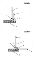
- the Figure 1 illustrates a first embodiment and implementation of the machining method of the invention.
- a part 2 to be machined for example a metal or plastic part, is subjected to a machining operation, such as drilling, cutting or the like, by means of a machining tool 1, by example a rotary or oscillating tool, such as a strawberry.
- the zone or region 5 of the part 2 machined by the tool 1 undergoes a heating due to friction or the like occurring between the tool 1 and the part 2.
- all or part of the machining zone 5, which can be heated, is cooled by distributing liquid nitrogen at the level of said machining zone 5 and possibly also at the level of the tool 1 .
- a single jet 6 formed of liquid nitrogen mixed with CO 2 particles in solid form, typically a mixture of liquid nitrogen containing from 10 to 70% by weight of CO 2 particles in solid form, that is to say in the form of dry ice.
- This liquid nitrogen / solid CO 2 mixture is produced in situ, either in the distribution nozzle 3 which delivers the single jet 6, or upstream of said nozzle 3, for example in a mixing chamber connected, on the one hand, to a source of solid CO 2 and, secondly, a source of liquid nitrogen.
- the Figure 2 illustrates a second embodiment of the invention similar to that of the Figure 1 but in which the injection of liquid nitrogen and solid CO 2 particles is done using two injection nozzles 3, 4, for example here a first nozzle 3 arranged vertically and a second nozzle 4 arranged horizontally .
- the two nozzles 3, 4 can each dispense a liquid nitrogen / solid CO 2 mixture.
- one of the nozzles 3, 4 can dispense liquid nitrogen and the other the solid CO 2 particles, mixing them in situ at the machining zone 5 to be cooled.
- the CO 2 particles used are solid at cryogenic temperature, that is to say typically at less than -150 ° C. but become gaseous as soon as their temperature exceeds about -78 ° C., therefore a fortiori at room temperature.
- the CO 2 has a thermal conductivity at -196 ° C, which is the temperature of the liquid nitrogen, of the order of 0.05 W / (mK), thus much higher than that of the nitrogen gas at same temperature, namely 0.0145 W / (mK).
- the solid CO 2 in addition to its role of disintegration of the calefaction layer forming at the interface between the liquid nitrogen and the surface of the part 2, also has a thermal bridge effect and provides frigories for cooling also the machining area.
- the CO 2 will not create secondary waste to be reprocessed, nor degrade or hinder the actual machining process, because of its low abrasive effect.
- a CO 2 premix in the form of dry ice and liquid nitrogen is produced before injection to the machining zone 5.
- the solid CO 2 particles are cooled to about -196 ° C. that is, at the temperature of the liquid nitrogen in which they are.
- the liquid nitrogen / solid CO 2 mixture according to the invention must contain more than 10% by weight of CO 2 to obtain a notable effect of CO 2 and a maximum of 70% by weight of CO 2 in order to maintain a mixing viscosity that is compatible with the injection processes.
- the flow of cryogenic liquid nitrogen / CO 2 solid mixture can be injected vertically as illustrated in FIG. Figure 1 but also horizontally or at a given angle between the horizontal position and the vertical position.
- the injection angle most suitable for a given machining can easily be determined empirically, on a case by case basis, particularly as a function of the configuration of the part and / or the tool, of the efficiency of the cooling to be obtained. ..
- the piece 2 to be machined and cooled may be formed of a metallic material, ferrous or non-ferrous, such as stainless steel, titanium or an alloy thereof, an alloy based on chromium or nickel, such as an Inconel, or a non-metallic material, in particular a plastic polymer, such as a ductile high-performance type plastic (PPS, PI, PAI, etc.) or a ceramic.
- a metallic material ferrous or non-ferrous, such as stainless steel, titanium or an alloy thereof, an alloy based on chromium or nickel, such as an Inconel, or a non-metallic material, in particular a plastic polymer, such as a ductile high-performance type plastic (PPS, PI, PAI, etc.) or a ceramic.
- cooling is performed on the machining zone 5 but it is also possible to simultaneously cool all or part of the tool 1 itself by means of the liquid nitrogen / solid CO 2 mixture.
Landscapes
- Engineering & Computer Science (AREA)
- Mechanical Engineering (AREA)
- Physics & Mathematics (AREA)
- Fluid Mechanics (AREA)
- Auxiliary Devices For Machine Tools (AREA)
Description
- L'invention porte sur un procédé d'usinage d'une pièce à usiner avec un outil d'usinage, notamment de perçage ou de coupage, dans lequel on refroidit efficacement la zone d'usinage au moyen d'un mélange cryogénique formé d'azote liquide et de particules de CO2 solide, ainsi que sur une installation de mise en oeuvre de ce procédé.
- Lors d'une opération d'usinage d'une pièce métallique, par exemple une opération de découpe ou de perçage mécanique, la friction, les frottements et la génération de chaleur de la zone d'usinage ou zone d'échauffement sont des problèmes fréquents qui nécessitent souvent une mise en place d'une lubrification et/ou d'un refroidissement efficace du matériau métallique usiné.
- Pour ce faire, un composé refroidissant et/ou lubrifiant, typiquement de l'eau ou de l'huile par exemple, est appliqué au contact de la zone usinée ou zone d'échauffement, ce qui permet non seulement de refroidir plus ou moins efficacement cette zone mais aussi de la lubrifier de sorte d'améliorer la durée de vie de l'outil d'usinage, d'améliorer la précision dimensionnelle et/ou de diminuer la rugosité surfacique de l'objet usiné.
- Par composé refroidissant et/ou lubrifiant, on entend tout corps permettant de refroidir et éventuellement de lubrifier les pièces ou éléments en contact, c'est-à-dire matériau et outil, et ainsi de diminuer la température des pièces ou éléments considérées, par exemple l'eau ou la vapeur d'eau, les huiles, un gaz...
- La diminution de température engendrée par le contact avec le composé refroidissant permet aussi d'améliorer les paramètres d'usinage et ainsi d'augmenter la productivité globale de l'opération d'usinage.
- Toutefois, il s'avère que les composés refroidissants et/ou lubrifiants classiques ne sont pas assez efficaces pour pouvoir refroidir efficacement certains matériaux durs, tel par exemple l'acier inoxydable à fortes vitesses d'usinage, pendant leur usinage car la chaleur produite par les frottements de l'outil sur ces matériaux durs est trop importante pour être absorbée efficacement par ces composés classiques.
- Il s'ensuit alors une durée de vie de l'outil fortement réduite, voire des défauts d'usinage causés par une augmentation excessive de la température du matériau.
- De plus, pour certaines applications, telles l'usinage de pièces utilisées dans le médical, tout lubrifiant chimique est à proscrire à cause de problèmes de contamination de surface.
- Enfin, pour des raisons environnementales, les lubrifiants chimiques sont de moins en moins utilisés.
- Une alternative à l'utilisation de lubrifiants chimiques est l'usinage à sec. Toutefois, la mauvaise évacuation des calories générées empêche l'usinage à sec à grandes cadences.
- Par ailleurs, il a été proposé par le document
EP-A-35145 - De manière similaire, le document
US-A-3971114 a proposé d'utiliser du fréon 12 comme gaz de refroidissement. Cette solution n'est pas idéale car, là encore, la capacité de refroidissement du fréon est limitée et d'autre part, le fréon est susceptible de poser des problèmes environnementaux. - Le document
EP-A-1580284 propose quant à lui d'utiliser de l'argon liquide ou de l'hélium liquide, de manière alternative au CO2 liquide, en tant que fluide lubrifiant et refroidissant pendant un usinage. Or, on comprend immédiatement qu'une telle solution n'est pas viable ou alors que très limitée au plan industriel du fait des contraintes importantes de coût qu'elle engendre, ainsi que des difficultés de mises en oeuvre qu'elle peut engendrer, notamment en cas d'usage d'hélium liquide. - En outre, il a aussi été proposé par
EP-A-1580284 et également par les documentsWO-A-9960079 EP-A-2155451 etEP-A-1775064 , d'utiliser de l'azote liquide à pression atmosphérique en tant que fluide lubrifiant et refroidissant pendant un usinage. - En effet, à la pression atmosphérique, l'azote liquide est à environ -196°C et son apport frigorifique est remarquable, ce qui en fait une solution nettement meilleure que les autres gaz proposés.
- A titre d'exemple, la durée de vie d'un outil de coupe revêtu de carbure de tungstène utilisé pour couper de l'acier inoxydable à une vitesse de 100 m/min sera 3 à 4 fois plus importante si on utilise de l'azote liquide à pression atmosphérique en lieu et place d'un lubrifiant standard, tel de l'eau ou de l'huile.
- Toutefois, l'azote liquide est connu pour créer une couche de caléfaction lorsqu'il rentre en contact avec une pièce plus chaude que lui, c'est-à-dire à une température supérieure à -196°C. Plus la pièce est chaude, plus la couche de caléfaction est importante.
- Ce point est particulièrement notable lors d'une opération d'usinage mécanique car la différence de température entre l'azote liquide et la pièce à usiner peut aller, par exemple, de 500 à 1000°C.
- Cette couche de caléfaction est constituée d'azote gazeux qui forme entre l'azote liquide et la pièce à usiner, une barrière thermique gazeuse limitant l'apport de frigories provenant de l'azote liquide.
- Or, ce moindre apport frigorifique limite l'évacuation des calories produites par l'usinage et limite de facto la productivité globale car le refroidissement et/ou la lubrification sera dès lors moins efficace.
- On comprend donc que l'usage d'azote liquide n'est pas idéal du fait de l'existence de cette couche de caléfaction.
- Par ailleurs, les documents
EP-A-1044762 etWO-A-2006/065869 divulguent du CO2 solide mélangé à de l'azote sous forme gazeuse. - En outre,
EP-A-1580284 concerne un procédé pour améliorer la surface de travail d'un outil pendant sa mise en forme par injection d'azote liquide à la surface de l'outil. - De là, le problème est de pouvoir améliorer le refroidissement par azote liquide durant une opération d'usinage d'un matériau, en particulier le perçage ou la découpe d'un matériau dur, tel l'acier au carbone, l'acier inoxydable, l'aluminium et ses alliages, ou un alliage à base de chrome et/ou de nickel, ou de titane...
- La solution proposée est un procédé d'usinage d'une pièce à usiner avec un outil d'usinage, dans lequel on refroidit au moins une partie de la zone d'usinage susceptible de s'échauffer pendant l'usinage de la pièce ou de l'outil d'usinage en distribuant de l'azote liquide au niveau de ladite zone d'usinage ou de l'outil, caractérisé en ce qu'on distribue en outre des particules de CO2 sous forme solide dans la zone d'usinage les particules de CO2 sous forme solide étant mélangées à l'azote liquide.
- En d'autres termes, selon l'invention, on propose de réaliser un refroidissement de la zone d'usinage et/ou de l'outil d'usinage, c'est-à-dire des éléments qui s'échauffent durant l'usinage proprement dit, grâce à l'envoi au contact de la zone d'usinage et éventuellement de l'outil lui-même, de particules solides mélangées à un fluide cryogénique à l'état liquide, c'est-à-dire l'azote liquide, qui est typiquement à une température de l'ordre de -196°C, de manière à casser tout ou partie de la couche de caléfaction susceptible de se former par vaporisation de l'azote liquide en azote gazeux au contact des éléments chauds, et ainsi améliorer notablement le refroidissement et/ou la lubrification de la zone d'usinage par rapport à une utilisation d'azote liquide seul.
- Il est à noter que dans le cadre de l'invention :
- le terme «distribuer» est considéré comme totalement équivalent aux termes
« injecter », « envoyer » ou « délivrer ». - les termes «zone d'usinage » et «zone d'échauffement » sont utilisés indifféremment les uns des autres pour désigner la région de la pièce à usiner qui est susceptible d'être échauffée du fait de l'usinage proprement dit.
- l'azote liquide est de l'azote (désignation chimique : N2) à l'état liquéfié, c'est-à-dire à une température typiquement de l'ordre de -190 à -200°C, en particulier à -196°C à pression atmosphérique (1 atm). La pureté de l'azote liquide est typiquement d'au moins 99% en volume, c'est-à-dire qu'il n'est pas exclu que l'azote puisse contenir des impuretés inévitables.
- les particules de CO2 sous forme solide sont des cristaux de dioxyde de carbone, couramment appelés « neige carbonique ».
- Selon le cas, le procédé de l'invention peut comprendre l'une ou plusieurs des caractéristiques suivantes :
- les particules de CO2 sous forme solide sont mélangées à l'azote liquide.
- on distribue des particules de CO2 sous forme solide.
- on distribue un jet de refroidissement formé d'azote liquide et de 10 à 70% en masse de particules de CO2 sous forme solide.
- le jet de refroidissement formé d'azote liquide et de particules solides est à une pression comprise entre 1 et 400 bars.
- on réalise le mélange d'azote liquide et de particules solides in situ, simultanément ou juste avant sa distribution.
- l'azote liquide et les particules solides sont distribués par une ou plusieurs buses de distribution.
- l'usinage est un perçage ou une découpe.
- la pièce à usiner est formée d'un matériau métallique, céramique, composite ou plastique.
- la pièce à usiner est formée d'un matériau métallique choisi parmi l'acier au carbone, l'aluminium et ses alliages, l'acier inoxydable, les alliages de nickel et/ou de chrome, et le titane et les alliages de titane.
- La présente invention va être décrite plus en détail en références aux Figures annexées parmi lesquelles :
- la
Figure 1 représente un premier mode de réalisation de l'invention et - la
Figure 2 représente un deuxième mode de réalisation de l'invention. - La
Figure 1 illustre un premier mode de réalisation et de mise en oeuvre du procédé d'usinage de l'invention. - Comme on le voit, une pièce 2 à usiner, par exemple une pièce métallique ou en plastique, est soumise à une opération d'usinage, tel un perçage, un coupage ou autre, au moyen d'un outil d'usinage 1, par exemple un outil rotatif ou oscillant, telle une fraise.
- Durant la durée de l'usinage, la zone ou région 5 de la pièce 2 usinée par l'outil 1 subit un échauffement du fait des frottements ou analogues qui se produisent entre l'outil 1 et la pièce 2.
- Afin d'atténuer cet échauffement, on refroidit tout ou partie de la zone d'usinage 5 susceptible de s'échauffer en distribuant de l'azote liquide au niveau de ladite zone d'usinage 5 et éventuellement aussi au niveau de l'outil 1.
- Dans ce premier mode de réalisation, on envoie vers la zone d'usinage 5 un jet unique 6 formé d'azote liquide mélangé à des particules de CO2 sous forme solide, typiquement un mélange d'azote liquide contenant de 10 à 70% en masse de particules de CO2 sous forme solide, c'est-à-dire sous forme de neige carbonique.
- Ce mélange azote liquide/CO2 solide est réalisé in situ, soit dans la buse de distribution 3 qui délivre le jet unique 6, soit en amont de ladite buse 3, par exemple dans une chambre de mélange reliée, d'une part, à une source de CO2 solide et, d'autre part, à une source d'azote liquide.
- La
Figure 2 illustre un deuxième mode de réalisation de l'invention analogue à celle de laFigure 1 mais dans lequel l'injection de l'azote liquide et des particules de CO2 solide se fait à l'aide de deux buses d'injection 3, 4, par exemple ici une première buse 3 agencée verticalement et une deuxième buse 4 agencée horizontalement. - Dans ce deuxième mode de réalisation, les deux buses 3, 4 peuvent chacune distribuer un mélange azote liquide/CO2 solide.
- De manière alternative, l'une des buses 3,4 peut distribuer de l'azote liquide et l'autre les particules de CO2 solide, leur mélange se faisant in situ au niveau de la zone d'usinage 5 à refroidir.
- On peut également imaginer de distribuer un mélange azote liquide/CO2 solide au moyen de l'un des deux buses 3, 4 et d'utiliser l'autre buse pour distribuer uniquement de l'azote liquide ou du CO2 sous forme solide.
- D'une façon générale, les particules de CO2 utilisées sont solides à température cryogénique, c'est-à-dire typiquement à moins de -150°C mais deviennent gazeuses dès que leur température dépasse environ -78 °C, donc a fortiori à température ambiante.
- En effet, le CO2 a une conductivité thermique à -196°C, qui est la température de l'azote liquide, de l'ordre de 0.05 W/(m.K), donc nettement supérieure à celle de l'azote gazeux à la même température, à savoir 0.0145 W/(m.K).
- Dans le cadre de l'invention (
Fig. 1 et 2 ), le CO2 solide, outre son rôle de délitement de la couche de caléfaction se formant à l'interface entre l'azote liquide et la surface de la pièce 2, a également un effet de pont thermique et apporte des frigories permettant de refroidir aussi la zone d'usinage. - En outre, le CO2 ne va pas créer de déchets secondaires devant être retraités, ni dégrader ou gêner le processus d'usinage proprement dit, du fait de son faible effet abrasif.
- De préférence, on fabrique un prémélange de CO2 sous forme de neige carbonique et d'azote liquide avant injection vers la zone d'usinage 5. Dans ces conditions, les particules de CO2 solide sont refroidies à -196°C environ, c'est-à-dire à la température de l'azote liquide dans lesquelles elles se trouvent.
- Des essais expérimentaux ont montré qu'un refroidissement par immersion d'une pièce massive en acier chauffée à une température de 20 °C dans de l'azote liquide jusqu'à une température donnée de l'ordre de -190 °C nécessite une durée de refroidissement qui est 50 % supérieure à celle nécessaire pour obtenir le même refroidissement en utilisant un mélange formé d'azote liquide et de 30% en masse de CO2.
- Dès lors, on comprend immédiatement l'intérêt d'utiliser un mélange neige carbonique/azote liquide en tant que fluide refroidissant/lubrifiant d'usinage.
- En effet, durant ces essais, il a été mis en évidence que les particules de CO2 solide viennent limiter drastiquement l'effet de la couche de caléfaction créée par l'azote liquide au contact de la pièce à refroidir, ce qui améliore les transferts de chaleur.
- Le mélange azote liquide/CO2 solide selon l'invention doit contenir plus de 10% en masse de CO2 pour obtenir un effet notable du CO2 et au maximum 70 % en masse de CO2 pour conserver une viscosité de mélange compatible avec les procédés d'injection.
- Le flux de mélange cryogénique azote liquide/CO2 solide peut être injecté verticalement comme illustré en
Figure 1 mais aussi horizontalement ou selon un angle donné compris entre la position horizontale et la position verticale. L'angle d'injection le plus adapté à un usinage donné peut aisément être déterminé empiriquement, au cas par cas, en fonction notamment de la configuration de la pièce et/ou de l'outil, de l'efficacité du refroidissement à obtenir... - La pièce 2 à usiner et à refroidir peut être formée d'un matériau métallique, ferreux ou non, tel de l'acier inoxydable, du titane ou un de ses alliages, un alliage à base de chrome ou de nickel, tel un Inconel, ou d'un matériau non métallique, en particulier polymère plastique, tel qu'un plastique de type à hautes performances ductiles (PPS, PI, PAI...) ou d'une céramique.
- Préférentiellement, on opère à un refroidissement de la zone 5 d'usinage mais il est également possible de procéder simultanément à un refroidissement de tout ou partie de l'outil 1 lui-même au moyen du mélange azote liquide/CO2 solide.
Claims (8)
- Procédé d'usinage d'une pièce (2) à usiner avec un outil d'usinage (1), dans lequel on refroidit au moins une partie de la zone d'usinage (5) susceptible de s'échauffer pendant l'usinage de la pièce (2) ou de l'outil d'usinage (1) en distribuant de l'azote liquide au niveau de ladite zone d'usinage (5) et/ou de l'outil (1), caractérisé en ce qu'on distribue en outre des particules de CO2 sous forme solide, au moins dans la zone d'usinage (5), les particules de CO2 sous forme solide étant mélangées à l'azote liquide.
- Procédé selon la revendication précédente, caractérisé en ce qu'on distribue un jet de refroidissement formé d'azote liquide et de 10 à 70% en masse de particules de CO2 sous forme solide.
- Procédé selon l'une des revendications précédentes, caractérisé en ce que le jet de refroidissement formé d'azote liquide et de particules solides est à une pression comprise entre 1 et 400 bars.
- Procédé selon l'une des revendications précédentes, caractérisé en ce qu'on réalise le mélange d'azote liquide et de particules solides in situ, simultanément ou juste avant sa distribution.
- Procédé selon l'une des revendications précédentes, caractérisé en ce que l'azote liquide et les particules solides sont distribuées par une ou plusieurs buses (3, 4) de distribution.
- Procédé selon l'une des revendications précédentes, caractérisé en ce que l'usinage est un perçage, une découpe, un fraisage ou un tournage.
- Procédé selon l'une des revendications précédentes, caractérisé en ce que la pièce (2) à usiner est formée d'un matériau métallique, plastique, composite ou céramique.
- Procédé selon l'une des revendications précédentes, caractérisé en ce que la pièce à usiner (2) est formée d'un matériau métallique choisi parmi l'acier carbone, l'aluminium et ses alliages, l'acier inoxydable, les alliages de nickel et/ou de chrome, et le titane et les alliages de titane.
Applications Claiming Priority (2)
| Application Number | Priority Date | Filing Date | Title |
|---|---|---|---|
| FR1058638A FR2966371B1 (fr) | 2010-10-22 | 2010-10-22 | Procede et installation d'usinage avec refroidissement cryogenique |
| PCT/FR2011/052331 WO2012052650A1 (fr) | 2010-10-22 | 2011-10-06 | Procédé et installation d'usinage avec refroidissement cryogénique |
Publications (2)
| Publication Number | Publication Date |
|---|---|
| EP2629931A1 EP2629931A1 (fr) | 2013-08-28 |
| EP2629931B1 true EP2629931B1 (fr) | 2014-12-17 |
Family
ID=43984151
Family Applications (1)
| Application Number | Title | Priority Date | Filing Date |
|---|---|---|---|
| EP11779806.6A Active EP2629931B1 (fr) | 2010-10-22 | 2011-10-06 | Procédé d'usinage avec refroidissement cryogénique |
Country Status (7)
| Country | Link |
|---|---|
| US (1) | US20130209186A1 (fr) |
| EP (1) | EP2629931B1 (fr) |
| JP (1) | JP2013543797A (fr) |
| CN (1) | CN103180093B (fr) |
| ES (1) | ES2531848T3 (fr) |
| FR (1) | FR2966371B1 (fr) |
| WO (1) | WO2012052650A1 (fr) |
Families Citing this family (15)
| Publication number | Priority date | Publication date | Assignee | Title |
|---|---|---|---|---|
| FR2995808B1 (fr) * | 2012-09-21 | 2015-05-15 | Eads Europ Aeronautic Defence | Outil de percage et dispositif de percage a refroidissement cryogenique et procede de percage d'un empilage de materiaux heterogenes |
| DE102012112189A1 (de) * | 2012-12-12 | 2014-06-12 | Sandvik Materials Technology Deutschland Gmbh | Vorrichtung und Verfahren zum Abstechen eines Rohrs |
| CN104903047B (zh) * | 2012-12-12 | 2019-02-15 | 山特维克原料技术德国公开股份有限公司 | 用于加工管子的端部的加工机器和方法 |
| DE102013102704A1 (de) | 2013-03-18 | 2014-09-18 | Sandvik Materials Technology Deutschland Gmbh | Verfahren zum Herstellen eines Stahlrohres mit Reinigung der Rohrinnenwand |
| DE102013102703A1 (de) | 2013-03-18 | 2014-09-18 | Sandvik Materials Technology Deutschland Gmbh | Verfahren zum Herstellen eines Stahlrohres mit Reinigung der Rohraußenwand |
| CN105081353B (zh) * | 2014-05-13 | 2017-07-07 | 重庆润泽医药有限公司 | 一种多孔金属的车削方法 |
| CN104308646A (zh) * | 2014-09-05 | 2015-01-28 | 攀钢集团成都钢钒有限公司 | 用于钛合金油管接头加工工序中的冷却方法 |
| FR3068707B1 (fr) * | 2017-07-10 | 2020-07-31 | Air Liquide | Composition, dispositif et procede de refroidissement a temperature cryogenique |
| CN108406434A (zh) * | 2018-03-09 | 2018-08-17 | 东莞安默琳机械制造技术有限公司 | 基于液氮冷却润滑的硬质合金切削方法 |
| CN108568702A (zh) * | 2018-06-27 | 2018-09-25 | 湖北三江航天江北机械工程有限公司 | 钛合金工件的低温切削工艺 |
| US20220339716A1 (en) * | 2019-02-26 | 2022-10-27 | University Of Kentucky Research Foundation | High speed multi-axis machine tool |
| CN110026815B (zh) * | 2019-04-19 | 2021-04-09 | 沈阳理工大学 | 一种铣孔装置 |
| CN114234512B (zh) * | 2021-11-18 | 2023-05-12 | 山东宝成制冷设备有限公司 | 一种靶点式降温设备 |
| CN118237973A (zh) * | 2024-05-30 | 2024-06-25 | 成都飞机工业(集团)有限责任公司 | 一种用于低温干式铣削的液氮外冷环喷装置及加工方法 |
| JP7762990B1 (ja) * | 2024-05-31 | 2025-10-31 | 株式会社テクトレージ | 冷却装置及び冷却方法 |
Family Cites Families (12)
| Publication number | Priority date | Publication date | Assignee | Title |
|---|---|---|---|---|
| US3971114A (en) | 1972-01-27 | 1976-07-27 | Dudley George M | Machine tool having internally routed cryogenic fluid for cooling interface between cutting edge of tool and workpiece |
| DE3007512C2 (de) | 1980-02-28 | 1982-04-29 | Fa. Hermann Heye, 3063 Obernkirchen | Vorrichtung zum Aufbringen einer Schmier- oder Trennflüssigkeit auf ein Glasformmaschinenteil |
| US5733174A (en) * | 1994-01-07 | 1998-03-31 | Lockheed Idaho Technologies Company | Method and apparatus for cutting, abrading, and drilling with sublimable particles and vaporous liquids |
| WO1999060079A2 (fr) | 1998-05-21 | 1999-11-25 | The Trustees Of Columbia University In The City Of New York | Ensemble outil de fraisage cryogenique relie a de l'azote liquide par un raccord rotatif |
| DE19915619A1 (de) * | 1999-04-07 | 2000-10-19 | Multimatic Oberflaechentechnik | Verfahren zum Abführen von Zerspanungsprodukten eines zerspanenden Bearbeitungsverfahrens |
| US6564682B1 (en) * | 2000-11-14 | 2003-05-20 | Air Products And Chemicals, Inc. | Machine tool distributor for cryogenic cooling of cutting tools on a turret plate |
| US20030110781A1 (en) * | 2001-09-13 | 2003-06-19 | Zbigniew Zurecki | Apparatus and method of cryogenic cooling for high-energy cutting operations |
| US7513121B2 (en) * | 2004-03-25 | 2009-04-07 | Air Products And Chemicals, Inc. | Apparatus and method for improving work surface during forming and shaping of materials |
| MX2007007080A (es) * | 2004-12-13 | 2007-12-07 | Cool Clean Technologies Inc | Dispositivo para aplicar composicion criogenica y metodo de uso del mismo. |
| DE102005005638B3 (de) * | 2005-02-05 | 2006-02-09 | Cryosnow Gmbh | Verfahren und Vorrichtung zum Reinigen, Aktivieren oder Vorbehandeln von Werkstücken mittels Kohlendioxidschnee-Strahlen |
| US7390240B2 (en) | 2005-10-14 | 2008-06-24 | Air Products And Chemicals, Inc. | Method of shaping and forming work materials |
| US20080276771A1 (en) | 2007-05-07 | 2008-11-13 | Air Products And Chemicals, Inc. | Method For Hardening A Machined Article |
-
2010
- 2010-10-22 FR FR1058638A patent/FR2966371B1/fr not_active Expired - Fee Related
-
2011
- 2011-10-06 WO PCT/FR2011/052331 patent/WO2012052650A1/fr not_active Ceased
- 2011-10-06 CN CN201180050828.2A patent/CN103180093B/zh active Active
- 2011-10-06 ES ES11779806.6T patent/ES2531848T3/es active Active
- 2011-10-06 EP EP11779806.6A patent/EP2629931B1/fr active Active
- 2011-10-06 JP JP2013534360A patent/JP2013543797A/ja active Pending
- 2011-10-06 US US13/880,775 patent/US20130209186A1/en not_active Abandoned
Also Published As
| Publication number | Publication date |
|---|---|
| CN103180093B (zh) | 2016-06-01 |
| US20130209186A1 (en) | 2013-08-15 |
| FR2966371B1 (fr) | 2013-08-16 |
| CN103180093A (zh) | 2013-06-26 |
| WO2012052650A1 (fr) | 2012-04-26 |
| EP2629931A1 (fr) | 2013-08-28 |
| ES2531848T3 (es) | 2015-03-20 |
| FR2966371A1 (fr) | 2012-04-27 |
| JP2013543797A (ja) | 2013-12-09 |
Similar Documents
| Publication | Publication Date | Title |
|---|---|---|
| WO2012052650A1 (fr) | Procédé et installation d'usinage avec refroidissement cryogénique | |
| Kui et al. | Recent progress and evolution of coolant usages in conventional machining methods: a comprehensive review | |
| Wang et al. | Tool wear performance in face milling Inconel 182 using minimum quantity lubrication with different nozzle positions | |
| Park et al. | Tool wear analysis on coated and uncoated carbide tools in inconel machining | |
| Wenlong et al. | Anti-friction and wear resistance analysis of cemented carbide coatings | |
| Dhar et al. | Wear behavior of uncoated carbide inserts under dry, wet and cryogenic cooling conditions in turning C-60 steel | |
| FR2602272A1 (fr) | Moteur a combustion interne comprenant un bloc-cylindres a zone renforcee par des fibres, et des pistons a segments coulissants dans les alesages des cylindres | |
| EP2334836B9 (fr) | Materiau composite hierarchique | |
| Tao et al. | Effect of Cu-coated diamond on the formation of Cu–Sn-based diamond composites fabricated by laser-powder bed fusion | |
| Nguyen et al. | Study of the formation of the alloyed surface layer during plasma heating of mixtures of Cu-Sn/CrXCY alloys | |
| EP2451612A1 (fr) | Coupage par jet de fluide cryogénique liquide additionné de particules abrasives | |
| Akyuz | Machinability of magnesium and its alloys | |
| CA2577059A1 (fr) | Coupage laser du titane avec melanges gazeux ar/he | |
| Cheng et al. | Enhancement of mechanical and tribological performance of Ti–6Al–4V alloy by laser surface alloying with Inconel 625 and SiC precursor materials | |
| JPWO2013129320A1 (ja) | 被覆回転ツールおよびその製造方法 | |
| Tao et al. | Effect of different Ti doping modes on diamond/Cu–Sn composites forming via laser powder bed melting | |
| Yang et al. | Effects of micro dimple’s topography parameters on wear resistance of laser textured alcrn coating under starved lubrication condition | |
| FR2987967A1 (fr) | Tuyere pour torche a plasma d'arc avec element interne demontable | |
| Huang et al. | Improved Wear Resistance of High-Entropy Alloy Composite Coatings Reinforced With Cr3C2 Carbide via Laser Cladding | |
| Younes et al. | Investigation on the surface structure and tribological characterization of 10 wt.% ZrO2-reinforced alumina prepared by flame spray coating | |
| Sakiru et al. | Thin surface layers of iron-based alloys deposited by TIG hardfacing | |
| US20050012252A1 (en) | Cold hearth and skull for refining metals which seal together to prevent overflow of molten metal therebetween | |
| EP3325681B1 (fr) | Procede de fabrication d'un piece en un materiau composite al/al3b48c2 | |
| Shi et al. | High-Temperature Tribological Performance of Nano-Modified Multimodal Cr3C2-NiCr Coatings | |
| Bhirud et al. | Alternative techniques for reducing the use of cutting fluids |
Legal Events
| Date | Code | Title | Description |
|---|---|---|---|
| PUAI | Public reference made under article 153(3) epc to a published international application that has entered the european phase |
Free format text: ORIGINAL CODE: 0009012 |
|
| 17P | Request for examination filed |
Effective date: 20130522 |
|
| AK | Designated contracting states |
Kind code of ref document: A1 Designated state(s): AL AT BE BG CH CY CZ DE DK EE ES FI FR GB GR HR HU IE IS IT LI LT LU LV MC MK MT NL NO PL PT RO RS SE SI SK SM TR |
|
| RIN1 | Information on inventor provided before grant (corrected) |
Inventor name: ROTMAN, FREDERIC Inventor name: QUINTARD, JACQUES Inventor name: TRUCHOT, CHARLES Inventor name: RICHARD, FREDERIC |
|
| DAX | Request for extension of the european patent (deleted) | ||
| 17Q | First examination report despatched |
Effective date: 20140320 |
|
| GRAP | Despatch of communication of intention to grant a patent |
Free format text: ORIGINAL CODE: EPIDOSNIGR1 |
|
| INTG | Intention to grant announced |
Effective date: 20140709 |
|
| GRAS | Grant fee paid |
Free format text: ORIGINAL CODE: EPIDOSNIGR3 |
|
| GRAA | (expected) grant |
Free format text: ORIGINAL CODE: 0009210 |
|
| AK | Designated contracting states |
Kind code of ref document: B1 Designated state(s): AL AT BE BG CH CY CZ DE DK EE ES FI FR GB GR HR HU IE IS IT LI LT LU LV MC MK MT NL NO PL PT RO RS SE SI SK SM TR |
|
| REG | Reference to a national code |
Ref country code: GB Ref legal event code: FG4D Free format text: NOT ENGLISH |
|
| REG | Reference to a national code |
Ref country code: CH Ref legal event code: EP |
|
| REG | Reference to a national code |
Ref country code: IE Ref legal event code: FG4D Free format text: LANGUAGE OF EP DOCUMENT: FRENCH |
|
| REG | Reference to a national code |
Ref country code: AT Ref legal event code: REF Ref document number: 701532 Country of ref document: AT Kind code of ref document: T Effective date: 20150115 |
|
| REG | Reference to a national code |
Ref country code: DE Ref legal event code: R096 Ref document number: 602011012389 Country of ref document: DE Effective date: 20150129 |
|
| REG | Reference to a national code |
Ref country code: ES Ref legal event code: FG2A Ref document number: 2531848 Country of ref document: ES Kind code of ref document: T3 Effective date: 20150320 |
|
| PG25 | Lapsed in a contracting state [announced via postgrant information from national office to epo] |
Ref country code: FI Free format text: LAPSE BECAUSE OF FAILURE TO SUBMIT A TRANSLATION OF THE DESCRIPTION OR TO PAY THE FEE WITHIN THE PRESCRIBED TIME-LIMIT Effective date: 20141217 Ref country code: NO Free format text: LAPSE BECAUSE OF FAILURE TO SUBMIT A TRANSLATION OF THE DESCRIPTION OR TO PAY THE FEE WITHIN THE PRESCRIBED TIME-LIMIT Effective date: 20150317 Ref country code: LT Free format text: LAPSE BECAUSE OF FAILURE TO SUBMIT A TRANSLATION OF THE DESCRIPTION OR TO PAY THE FEE WITHIN THE PRESCRIBED TIME-LIMIT Effective date: 20141217 |
|
| REG | Reference to a national code |
Ref country code: LT Ref legal event code: MG4D |
|
| PG25 | Lapsed in a contracting state [announced via postgrant information from national office to epo] |
Ref country code: GR Free format text: LAPSE BECAUSE OF FAILURE TO SUBMIT A TRANSLATION OF THE DESCRIPTION OR TO PAY THE FEE WITHIN THE PRESCRIBED TIME-LIMIT Effective date: 20150318 Ref country code: SE Free format text: LAPSE BECAUSE OF FAILURE TO SUBMIT A TRANSLATION OF THE DESCRIPTION OR TO PAY THE FEE WITHIN THE PRESCRIBED TIME-LIMIT Effective date: 20141217 Ref country code: LV Free format text: LAPSE BECAUSE OF FAILURE TO SUBMIT A TRANSLATION OF THE DESCRIPTION OR TO PAY THE FEE WITHIN THE PRESCRIBED TIME-LIMIT Effective date: 20141217 Ref country code: RS Free format text: LAPSE BECAUSE OF FAILURE TO SUBMIT A TRANSLATION OF THE DESCRIPTION OR TO PAY THE FEE WITHIN THE PRESCRIBED TIME-LIMIT Effective date: 20141217 Ref country code: HR Free format text: LAPSE BECAUSE OF FAILURE TO SUBMIT A TRANSLATION OF THE DESCRIPTION OR TO PAY THE FEE WITHIN THE PRESCRIBED TIME-LIMIT Effective date: 20141217 |
|
| REG | Reference to a national code |
Ref country code: AT Ref legal event code: MK05 Ref document number: 701532 Country of ref document: AT Kind code of ref document: T Effective date: 20141217 |
|
| PG25 | Lapsed in a contracting state [announced via postgrant information from national office to epo] |
Ref country code: NL Free format text: LAPSE BECAUSE OF FAILURE TO SUBMIT A TRANSLATION OF THE DESCRIPTION OR TO PAY THE FEE WITHIN THE PRESCRIBED TIME-LIMIT Effective date: 20141217 |
|
| PG25 | Lapsed in a contracting state [announced via postgrant information from national office to epo] |
Ref country code: EE Free format text: LAPSE BECAUSE OF FAILURE TO SUBMIT A TRANSLATION OF THE DESCRIPTION OR TO PAY THE FEE WITHIN THE PRESCRIBED TIME-LIMIT Effective date: 20141217 Ref country code: RO Free format text: LAPSE BECAUSE OF FAILURE TO SUBMIT A TRANSLATION OF THE DESCRIPTION OR TO PAY THE FEE WITHIN THE PRESCRIBED TIME-LIMIT Effective date: 20141217 Ref country code: SK Free format text: LAPSE BECAUSE OF FAILURE TO SUBMIT A TRANSLATION OF THE DESCRIPTION OR TO PAY THE FEE WITHIN THE PRESCRIBED TIME-LIMIT Effective date: 20141217 |
|
| PG25 | Lapsed in a contracting state [announced via postgrant information from national office to epo] |
Ref country code: AT Free format text: LAPSE BECAUSE OF FAILURE TO SUBMIT A TRANSLATION OF THE DESCRIPTION OR TO PAY THE FEE WITHIN THE PRESCRIBED TIME-LIMIT Effective date: 20141217 Ref country code: PL Free format text: LAPSE BECAUSE OF FAILURE TO SUBMIT A TRANSLATION OF THE DESCRIPTION OR TO PAY THE FEE WITHIN THE PRESCRIBED TIME-LIMIT Effective date: 20141217 Ref country code: IS Free format text: LAPSE BECAUSE OF FAILURE TO SUBMIT A TRANSLATION OF THE DESCRIPTION OR TO PAY THE FEE WITHIN THE PRESCRIBED TIME-LIMIT Effective date: 20150417 |
|
| REG | Reference to a national code |
Ref country code: DE Ref legal event code: R097 Ref document number: 602011012389 Country of ref document: DE |
|
| PLBE | No opposition filed within time limit |
Free format text: ORIGINAL CODE: 0009261 |
|
| REG | Reference to a national code |
Ref country code: FR Ref legal event code: PLFP Year of fee payment: 5 |
|
| STAA | Information on the status of an ep patent application or granted ep patent |
Free format text: STATUS: NO OPPOSITION FILED WITHIN TIME LIMIT |
|
| PG25 | Lapsed in a contracting state [announced via postgrant information from national office to epo] |
Ref country code: DK Free format text: LAPSE BECAUSE OF FAILURE TO SUBMIT A TRANSLATION OF THE DESCRIPTION OR TO PAY THE FEE WITHIN THE PRESCRIBED TIME-LIMIT Effective date: 20141217 |
|
| 26N | No opposition filed |
Effective date: 20150918 |
|
| PG25 | Lapsed in a contracting state [announced via postgrant information from national office to epo] |
Ref country code: SI Free format text: LAPSE BECAUSE OF FAILURE TO SUBMIT A TRANSLATION OF THE DESCRIPTION OR TO PAY THE FEE WITHIN THE PRESCRIBED TIME-LIMIT Effective date: 20141217 |
|
| PG25 | Lapsed in a contracting state [announced via postgrant information from national office to epo] |
Ref country code: LU Free format text: LAPSE BECAUSE OF FAILURE TO SUBMIT A TRANSLATION OF THE DESCRIPTION OR TO PAY THE FEE WITHIN THE PRESCRIBED TIME-LIMIT Effective date: 20151006 |
|
| REG | Reference to a national code |
Ref country code: CH Ref legal event code: PL |
|
| PG25 | Lapsed in a contracting state [announced via postgrant information from national office to epo] |
Ref country code: MC Free format text: LAPSE BECAUSE OF FAILURE TO SUBMIT A TRANSLATION OF THE DESCRIPTION OR TO PAY THE FEE WITHIN THE PRESCRIBED TIME-LIMIT Effective date: 20141217 |
|
| REG | Reference to a national code |
Ref country code: IE Ref legal event code: MM4A |
|
| PG25 | Lapsed in a contracting state [announced via postgrant information from national office to epo] |
Ref country code: CH Free format text: LAPSE BECAUSE OF NON-PAYMENT OF DUE FEES Effective date: 20151031 Ref country code: LI Free format text: LAPSE BECAUSE OF NON-PAYMENT OF DUE FEES Effective date: 20151031 |
|
| REG | Reference to a national code |
Ref country code: FR Ref legal event code: PLFP Year of fee payment: 6 |
|
| PG25 | Lapsed in a contracting state [announced via postgrant information from national office to epo] |
Ref country code: IE Free format text: LAPSE BECAUSE OF NON-PAYMENT OF DUE FEES Effective date: 20151006 |
|
| PG25 | Lapsed in a contracting state [announced via postgrant information from national office to epo] |
Ref country code: BG Free format text: LAPSE BECAUSE OF FAILURE TO SUBMIT A TRANSLATION OF THE DESCRIPTION OR TO PAY THE FEE WITHIN THE PRESCRIBED TIME-LIMIT Effective date: 20141217 Ref country code: HU Free format text: LAPSE BECAUSE OF FAILURE TO SUBMIT A TRANSLATION OF THE DESCRIPTION OR TO PAY THE FEE WITHIN THE PRESCRIBED TIME-LIMIT; INVALID AB INITIO Effective date: 20111006 Ref country code: SM Free format text: LAPSE BECAUSE OF FAILURE TO SUBMIT A TRANSLATION OF THE DESCRIPTION OR TO PAY THE FEE WITHIN THE PRESCRIBED TIME-LIMIT Effective date: 20141217 |
|
| PG25 | Lapsed in a contracting state [announced via postgrant information from national office to epo] |
Ref country code: CY Free format text: LAPSE BECAUSE OF FAILURE TO SUBMIT A TRANSLATION OF THE DESCRIPTION OR TO PAY THE FEE WITHIN THE PRESCRIBED TIME-LIMIT Effective date: 20141217 |
|
| PG25 | Lapsed in a contracting state [announced via postgrant information from national office to epo] |
Ref country code: MT Free format text: LAPSE BECAUSE OF FAILURE TO SUBMIT A TRANSLATION OF THE DESCRIPTION OR TO PAY THE FEE WITHIN THE PRESCRIBED TIME-LIMIT Effective date: 20141217 |
|
| REG | Reference to a national code |
Ref country code: FR Ref legal event code: PLFP Year of fee payment: 7 |
|
| PG25 | Lapsed in a contracting state [announced via postgrant information from national office to epo] |
Ref country code: TR Free format text: LAPSE BECAUSE OF FAILURE TO SUBMIT A TRANSLATION OF THE DESCRIPTION OR TO PAY THE FEE WITHIN THE PRESCRIBED TIME-LIMIT Effective date: 20141217 Ref country code: MK Free format text: LAPSE BECAUSE OF FAILURE TO SUBMIT A TRANSLATION OF THE DESCRIPTION OR TO PAY THE FEE WITHIN THE PRESCRIBED TIME-LIMIT Effective date: 20141217 |
|
| PG25 | Lapsed in a contracting state [announced via postgrant information from national office to epo] |
Ref country code: PT Free format text: LAPSE BECAUSE OF FAILURE TO SUBMIT A TRANSLATION OF THE DESCRIPTION OR TO PAY THE FEE WITHIN THE PRESCRIBED TIME-LIMIT Effective date: 20141217 |
|
| REG | Reference to a national code |
Ref country code: FR Ref legal event code: PLFP Year of fee payment: 8 |
|
| PG25 | Lapsed in a contracting state [announced via postgrant information from national office to epo] |
Ref country code: AL Free format text: LAPSE BECAUSE OF FAILURE TO SUBMIT A TRANSLATION OF THE DESCRIPTION OR TO PAY THE FEE WITHIN THE PRESCRIBED TIME-LIMIT Effective date: 20141217 |
|
| PGFP | Annual fee paid to national office [announced via postgrant information from national office to epo] |
Ref country code: DE Payment date: 20251021 Year of fee payment: 15 |
|
| PGFP | Annual fee paid to national office [announced via postgrant information from national office to epo] |
Ref country code: GB Payment date: 20251022 Year of fee payment: 15 |
|
| PGFP | Annual fee paid to national office [announced via postgrant information from national office to epo] |
Ref country code: IT Payment date: 20251022 Year of fee payment: 15 |
|
| PGFP | Annual fee paid to national office [announced via postgrant information from national office to epo] |
Ref country code: FR Payment date: 20251030 Year of fee payment: 15 |
|
| PGFP | Annual fee paid to national office [announced via postgrant information from national office to epo] |
Ref country code: BE Payment date: 20251021 Year of fee payment: 15 |
|
| PGFP | Annual fee paid to national office [announced via postgrant information from national office to epo] |
Ref country code: CZ Payment date: 20250930 Year of fee payment: 15 |
|
| PGFP | Annual fee paid to national office [announced via postgrant information from national office to epo] |
Ref country code: ES Payment date: 20251210 Year of fee payment: 15 |