EP2629842B1 - Electrode assembly - Google Patents
Electrode assembly Download PDFInfo
- Publication number
- EP2629842B1 EP2629842B1 EP11835058.6A EP11835058A EP2629842B1 EP 2629842 B1 EP2629842 B1 EP 2629842B1 EP 11835058 A EP11835058 A EP 11835058A EP 2629842 B1 EP2629842 B1 EP 2629842B1
- Authority
- EP
- European Patent Office
- Prior art keywords
- sponge
- electrode
- contact surface
- electrode assembly
- porous element
- Prior art date
- Legal status (The legal status is an assumption and is not a legal conclusion. Google has not performed a legal analysis and makes no representation as to the accuracy of the status listed.)
- Active
Links
- 239000011148 porous material Substances 0.000 claims description 30
- 238000000034 method Methods 0.000 claims description 16
- 230000000638 stimulation Effects 0.000 claims description 9
- 230000008878 coupling Effects 0.000 claims description 3
- 238000010168 coupling process Methods 0.000 claims description 3
- 238000005859 coupling reaction Methods 0.000 claims description 3
- 239000008151 electrolyte solution Substances 0.000 claims description 2
- 230000000712 assembly Effects 0.000 description 10
- 238000000429 assembly Methods 0.000 description 10
- 229920001971 elastomer Polymers 0.000 description 10
- 239000005060 rubber Substances 0.000 description 10
- 210000001519 tissue Anatomy 0.000 description 9
- 239000003792 electrolyte Substances 0.000 description 8
- 239000000463 material Substances 0.000 description 8
- 239000012530 fluid Substances 0.000 description 5
- 230000007246 mechanism Effects 0.000 description 5
- FAPWRFPIFSIZLT-UHFFFAOYSA-M Sodium chloride Chemical compound [Na+].[Cl-] FAPWRFPIFSIZLT-UHFFFAOYSA-M 0.000 description 4
- 239000000853 adhesive Substances 0.000 description 4
- 230000001070 adhesive effect Effects 0.000 description 4
- 210000004556 brain Anatomy 0.000 description 4
- 230000003247 decreasing effect Effects 0.000 description 4
- 229910052751 metal Inorganic materials 0.000 description 4
- 239000002184 metal Substances 0.000 description 4
- 230000000007 visual effect Effects 0.000 description 4
- 230000008901 benefit Effects 0.000 description 3
- 239000012212 insulator Substances 0.000 description 3
- 230000009467 reduction Effects 0.000 description 3
- 230000004044 response Effects 0.000 description 3
- 238000002560 therapeutic procedure Methods 0.000 description 3
- 208000019901 Anxiety disease Diseases 0.000 description 2
- 208000020401 Depressive disease Diseases 0.000 description 2
- PEDCQBHIVMGVHV-UHFFFAOYSA-N Glycerine Chemical compound OCC(O)CO PEDCQBHIVMGVHV-UHFFFAOYSA-N 0.000 description 2
- 239000004372 Polyvinyl alcohol Substances 0.000 description 2
- 230000009286 beneficial effect Effects 0.000 description 2
- 239000004020 conductor Substances 0.000 description 2
- 239000006185 dispersion Substances 0.000 description 2
- 239000007788 liquid Substances 0.000 description 2
- 239000007769 metal material Substances 0.000 description 2
- 230000008587 neuronal excitability Effects 0.000 description 2
- BASFCYQUMIYNBI-UHFFFAOYSA-N platinum Chemical compound [Pt] BASFCYQUMIYNBI-UHFFFAOYSA-N 0.000 description 2
- 229920002451 polyvinyl alcohol Polymers 0.000 description 2
- 239000011780 sodium chloride Substances 0.000 description 2
- OYPRJOBELJOOCE-UHFFFAOYSA-N Calcium Chemical compound [Ca] OYPRJOBELJOOCE-UHFFFAOYSA-N 0.000 description 1
- DGAQECJNVWCQMB-PUAWFVPOSA-M Ilexoside XXIX Chemical compound C[C@@H]1CC[C@@]2(CC[C@@]3(C(=CC[C@H]4[C@]3(CC[C@@H]5[C@@]4(CC[C@@H](C5(C)C)OS(=O)(=O)[O-])C)C)[C@@H]2[C@]1(C)O)C)C(=O)O[C@H]6[C@@H]([C@H]([C@@H]([C@H](O6)CO)O)O)O.[Na+] DGAQECJNVWCQMB-PUAWFVPOSA-M 0.000 description 1
- 229910021607 Silver chloride Inorganic materials 0.000 description 1
- 208000006011 Stroke Diseases 0.000 description 1
- 239000004809 Teflon Substances 0.000 description 1
- 229920006362 Teflon® Polymers 0.000 description 1
- 230000003213 activating effect Effects 0.000 description 1
- 230000004075 alteration Effects 0.000 description 1
- -1 anion salt Chemical class 0.000 description 1
- 230000003925 brain function Effects 0.000 description 1
- 229910052791 calcium Inorganic materials 0.000 description 1
- 239000011575 calcium Substances 0.000 description 1
- 210000001175 cerebrospinal fluid Anatomy 0.000 description 1
- 230000008859 change Effects 0.000 description 1
- 238000005094 computer simulation Methods 0.000 description 1
- 239000000470 constituent Substances 0.000 description 1
- 208000037265 diseases, disorders, signs and symptoms Diseases 0.000 description 1
- 208000035475 disorder Diseases 0.000 description 1
- 239000012777 electrically insulating material Substances 0.000 description 1
- 238000001827 electrotherapy Methods 0.000 description 1
- 230000006870 function Effects 0.000 description 1
- 239000011521 glass Substances 0.000 description 1
- 235000011187 glycerol Nutrition 0.000 description 1
- PCHJSUWPFVWCPO-UHFFFAOYSA-N gold Chemical compound [Au] PCHJSUWPFVWCPO-UHFFFAOYSA-N 0.000 description 1
- 239000010931 gold Substances 0.000 description 1
- 229910052737 gold Inorganic materials 0.000 description 1
- 239000011810 insulating material Substances 0.000 description 1
- 150000002500 ions Chemical class 0.000 description 1
- 230000004048 modification Effects 0.000 description 1
- 238000012986 modification Methods 0.000 description 1
- 210000000653 nervous system Anatomy 0.000 description 1
- 210000002569 neuron Anatomy 0.000 description 1
- 239000004033 plastic Substances 0.000 description 1
- 229920003023 plastic Polymers 0.000 description 1
- 229910052697 platinum Inorganic materials 0.000 description 1
- 208000020016 psychiatric disease Diseases 0.000 description 1
- 239000012783 reinforcing fiber Substances 0.000 description 1
- 150000003839 salts Chemical class 0.000 description 1
- 229920006395 saturated elastomer Polymers 0.000 description 1
- 229920002379 silicone rubber Polymers 0.000 description 1
- HKZLPVFGJNLROG-UHFFFAOYSA-M silver monochloride Chemical compound [Cl-].[Ag+] HKZLPVFGJNLROG-UHFFFAOYSA-M 0.000 description 1
- 229910052708 sodium Inorganic materials 0.000 description 1
- 239000011734 sodium Substances 0.000 description 1
- 239000000126 substance Substances 0.000 description 1
- 238000011179 visual inspection Methods 0.000 description 1
Images


Classifications
-
- A—HUMAN NECESSITIES
- A61—MEDICAL OR VETERINARY SCIENCE; HYGIENE
- A61N—ELECTROTHERAPY; MAGNETOTHERAPY; RADIATION THERAPY; ULTRASOUND THERAPY
- A61N1/00—Electrotherapy; Circuits therefor
- A61N1/02—Details
- A61N1/04—Electrodes
- A61N1/05—Electrodes for implantation or insertion into the body, e.g. heart electrode
- A61N1/0526—Head electrodes
-
- A—HUMAN NECESSITIES
- A61—MEDICAL OR VETERINARY SCIENCE; HYGIENE
- A61N—ELECTROTHERAPY; MAGNETOTHERAPY; RADIATION THERAPY; ULTRASOUND THERAPY
- A61N1/00—Electrotherapy; Circuits therefor
- A61N1/02—Details
- A61N1/04—Electrodes
- A61N1/0404—Electrodes for external use
- A61N1/0472—Structure-related aspects
-
- A—HUMAN NECESSITIES
- A61—MEDICAL OR VETERINARY SCIENCE; HYGIENE
- A61N—ELECTROTHERAPY; MAGNETOTHERAPY; RADIATION THERAPY; ULTRASOUND THERAPY
- A61N1/00—Electrotherapy; Circuits therefor
- A61N1/18—Applying electric currents by contact electrodes
- A61N1/32—Applying electric currents by contact electrodes alternating or intermittent currents
- A61N1/36—Applying electric currents by contact electrodes alternating or intermittent currents for stimulation
- A61N1/36014—External stimulators, e.g. with patch electrodes
- A61N1/36025—External stimulators, e.g. with patch electrodes for treating a mental or cerebral condition
-
- A—HUMAN NECESSITIES
- A61—MEDICAL OR VETERINARY SCIENCE; HYGIENE
- A61N—ELECTROTHERAPY; MAGNETOTHERAPY; RADIATION THERAPY; ULTRASOUND THERAPY
- A61N1/00—Electrotherapy; Circuits therefor
- A61N1/18—Applying electric currents by contact electrodes
- A61N1/32—Applying electric currents by contact electrodes alternating or intermittent currents
- A61N1/36—Applying electric currents by contact electrodes alternating or intermittent currents for stimulation
- A61N1/372—Arrangements in connection with the implantation of stimulators
- A61N1/375—Constructional arrangements, e.g. casings
-
- A—HUMAN NECESSITIES
- A61—MEDICAL OR VETERINARY SCIENCE; HYGIENE
- A61N—ELECTROTHERAPY; MAGNETOTHERAPY; RADIATION THERAPY; ULTRASOUND THERAPY
- A61N1/00—Electrotherapy; Circuits therefor
- A61N1/02—Details
- A61N1/04—Electrodes
- A61N1/0404—Electrodes for external use
- A61N1/0408—Use-related aspects
- A61N1/0456—Specially adapted for transcutaneous electrical nerve stimulation [TENS]
Definitions
- This disclosure relates to an electrode assembly and also systems and methods for delivering neurostimulation, such as transcranial direct current stimulation (“tDCS”) to a patient, using the electrode assembly.
- neurostimulation such as transcranial direct current stimulation (“tDCS)
- tDCS Transcranial direct current stimulation
- FR 2 452 938 describes a disposable electrode for electrotherapy comprising a conductive plate and hydrophilic material in an insulating envelope.
- an electrode assembly includes a substantially porous element configured to be coupled to an electrode for delivery of electrical current to a patient in a neurostimulation procedure.
- the substantially porous material defines a contact surface, at least a portion of which contacts the patient during the neurostimulation procedure.
- a first insulating member e.g., a rivet
- the substantially porous element has one or more edges that extend from the contact surface.
- the first insulating member is exposed at the contact surface near one of the edges.
- the first insulating member is positioned so that an outermost point of the exposed portion is no further from the nearest edge than approximately 50% of the exposed portion's width.
- the substantially porous element in some embodiments, has a corner at a point where the contact surface and two of the edges connect to one another and the first insulating member is exposed at the contact surface near the corner.
- the substantially porous element has one or more edges at which an opening is provided for receiving and gripping the electrode in a manner that facilitates a low resistance electrical connection between the substantially porous element and the electrode.
- a portion of the substantially porous material can be exposed at the contact surface between the exposed portion of the first insulating member and edge of the first insulating member that is closest to the exposed portion.
- the substantially porous element includes a first portion and a second portion.
- the first insulating member is configured to physically hold together the first portion and the second portion.
- the first insulating member includes a substantially cylindrical portion (that may or may not include two portions joined together) that extends through the first and second portions of the substantially porous member and a head at each end of the substantially cylindrical portion, wherein each head has a larger diameter than the substantially cylindrical portion.
- the first insulating member can be, for example, a rivet, a pin pushed into the contact surface of the substantially porous element or a sticker or adhesive material adhered to the contact surface of the substantially porous element.
- the substantially porous material is configured to absorb and at least partially contain an electrolyte in liquid form.
- a second insulating member is coupled to the substantially porous element and exposed at the contact surface.
- the first and second insulating members are spaced sufficiently far apart from one another so that the electrode can fit between the first and second insulating members.
- an electrode assembly in another aspect, includes a substantially porous element having a contact surface, at least a portion of which is configured to contact a patient during delivery of electrical current from the substantially porous element to the patient during a neurostimulation procedure, wherein the substantially porous element includes a first portion and a second portion.
- Two or more rivets are provided that are made of electrically insulating material and that pass through the first portion and second portion of the substantially porous element to hold the first and second portion together.
- Each rivet has a head portion exposed at the contact surface to prevent a portion of the contact surface from contacting the patient during the neurostimulation procedure.
- the rivets are positioned so that an innermost portion of each respective head is no further from a closest edge of the substantially porous element than approximately 150% of the head's diameter.
- a system in yet another aspect, includes a neurostimulation device (e.g., a tDCS device), at least two electrically conductive cables coupled to the neurostimulation device; an electrode coupled to the distal end of each respective one of the electrically conductive cables; and an electrode interface optionally removably coupled to at least one of the electrodes.
- Each electrode interface includes a substantially porous element physically coupled to the electrode for delivery of electrical current to a patient in a neurostimulation procedure.
- the substantially porous material defines a contact surface. At least a portion of the contact surface contacts the patient during the neurostimulation procedure.
- a first insulating member is coupled to the substantially porous element and exposed at the contact surface to prevent a portion of the contact surface from contacting the patient to deliver the electrical current during the neurostimulation procedure.
- the substantially porous element has one or more edges that extend from the contact surface, and the first insulating member is positioned so that an outermost point of the exposed portion is no further from the nearest edge than approximately 50% of the exposed portion's width.
- the substantially porous element typically has a corner at a point where the contact surface and two of the edges connect to one another and the first insulating member is exposed at the contact surface near the corner.
- the substantially porous element has one or more edges at which an opening is provided for receiving and gripping the electrode in a manner that facilitates a low resistance electrical connection between the substantially porous element and the electrode.
- a portion of the substantially porous material typically is exposed at the contact surface between the exposed portion of the first insulating member and edge of the first insulating member that is closest to the exposed portion.
- the substantially porous element has a first portion and a second portion.
- the first insulating member is configured to physically hold together the first portion and the second portion and the electrode is positioned between the first portion and the second portion of the substantially porous element.
- the first insulating member can be a rivet with a substantially cylindrical portion that extends through the first and second portions of the substantially porous member and a head at each end of the substantially cylindrical portion. Each head typically has a larger diameter than the substantially cylindrical portion.
- a second insulating member is coupled to the substantially porous element and exposed at the contact surface.
- the first and second insulating members are spaced sufficiently far apart from one another so as to accommodate the electrode, which is positioned between the first and second insulating members.
- a second insulating member is coupled to the substantially porous element and exposed at the contact surface.
- the first and second insulating members are exposed at a surface of the substantially porous material opposite the contact surface.
- the system further includes a strap for coupling the electrode interface to the patient.
- the strap can be, for example, between portions of the first and second insulating members that are exposed at the surface of the substantially porous material opposite the contact surface and the portions of the first and second insulating members extend over the strap to thereby couple the electrode interface to the strap.
- the first insulating member can be, for example, a pin pushed into the contact surface of the substantially porous element or a sticker or adhesive material adhered to the contact surface of the substantially porous element.
- the substantially porous material is adapted to and typically does contain an electrolyte in liquid form during the delivery of electrical current.
- the porous material thickness between the electrode and the skin may be desirable to increase the porous material thickness between the electrode and the skin to about 0.75 cm (i.e., three times 0.25 cm).
- the conductive rubber insert (of the electrode), when used in a sponge pocket, is greater than about 1 cm2 and preferably greater than about 4 cm2.
- An increase area of the rubber inset facilitates greater dispersion of current prior to reaching the skin.
- the size of the rubber inset or other electrode can be increased in area such that, in some instances, the distance from the edge of the rubber inset to the edge of the sponge pocket is less than about 1 cm. This can, in certain implementations, facilitate current reaching sponge edges including when higher resistivity porous material is used.
- the conductive rubber inset is not insulated on either surface such that current may exit from the rubber inset into both the top and bottom porous material which may, in some instances, enhance the spread of current toward the electrode edges. For this reason, the presence of a porous material with electrolyte over the rubber inset allows for current to exit from the top surface of the sponge.
- the conductive rubber inset may be replaced with a metal material where the metal material has a largely planar structure preferably allowing it to be placed on the surface of one of the porous materials. If the exposed area of the metal is less than about 2cm2, and especially if is less than about 1 cm2, then, in some instances, more than one conductor may be inserted into the sponges thus effectively increasing the total area of metal contacting the sponge to the combined area of the metal electrodes. For example, 4 electrodes of approximately 1cm2 can be positioned in one sponge and arranged such a line drawn between the centers of the electrode approximates a 4 cm x 4 cm square.
- sintered silver-chloride is used for the metal electrode, or gold, of platinum.
- the average size of pores on the porous material can range from about 80 microns to about 200 microns giving flexibility in the electrolyte uptake by the material.
- the volumetric expansion of the sponges can be about 0.15 cm 3 ; that is about 0.5 cm on the base (length), about 0.5 cm on the width, and about 6% (0.6 cm) on the thickness.
- the porous material can be made, for example, from polyvinyl alcohol (PVA) and Glycerin.
- PVA polyvinyl alcohol
- Glycerin polyvinyl alcohol
- the porous material may contain reinforcing fibers (threads) that enhance certain mechanical properties of the material and its durability.
- a structurally sound, low pain electrode assembly can be produced.
- the present application relates to an electrode assembly and systems and methods for delivering neurostimulation, such as transcranial direct current stimulation (“tDCS”) to a patient, using the electrode assembly.
- neurostimulation such as transcranial direct current stimulation (“tDCS)
- tDCS transcranial direct current stimulation
- tDCS uses a relatively constant, low flow of direct electrical current delivered directly to the brain area of a patient using small electrodes placed on the patient's skin (i.e., not directly on the patient's brain). More particularly, when the electrodes are placed in or near the regions of interest, electrical current flow through the electrodes induces intracerebral current flow. This intracerebral current flow can either increase or decrease neuronal excitability in specific areas being stimulated based on which type of stimulation is being used. This change of neuronal excitability leads to alteration of brain function, which can be used in various therapies as well as to provide more information about the functioning of the human brain. For example, tDCS can be used as therapy for certain physicological disorders, such as anxiety disorders and depression, as well as a tool for motor rehabilitation in stroke patients.
- physicological disorders such as anxiety disorders and depression
- the neurostimulation and tDCS techniques disclosed herein are completely noninvasive and, therefore, easy to administer, safe and convenient for patients or recipients of the tDCS.
- Figure 1 shows an exemplary tDCS device 100 connected via a pair of electrical cables 102a, 102b to electrode assemblies 104a, 104b at their respective distal ends, which are in contact with the head of a human patient 106.
- the electrode assemblies 104a, 104b can be secured to the patient's head including, for example, with an adhesive substance, with a strap or tape, by virtue of the electrode assemblies being integrated into a cap that the patient wears on his or her head.
- a first one of the electrode assemblies 104a is positioned near a front portion of the patient's head and a second one of the electrode assemblies 104b is positioned back on the top of the patient's head, displaced at least several centimeters away from the first electrode 104a.
- a variety of electrode configurations are possible.
- a human operator would program into the tDCS device 100 at least: 1) a target value of current; and 2) a duration for delivering the target value of current to the human patient 106.
- the human operator positions the electrodes, prepares them (e.g., by adding fluid, such as an electrolyte) and/or checking the resistance of the electrode connections to the patient
- the human operator prompts the tDCS device 100 to begin producing electrical current.
- the tDCS device 100 begins producing electrical current. More particularly, in response to the prompt from the human operator, the tDCS device 100 ramps the flow of electrical current from zero up to the target current value, delivers the target current value for approximately the duration that was specified by the human operator, and then ramps the flow of electrical current back to zero.
- the tDCS device 100 while electrical current is being produced, it flows from the tDCS device 100 to the human patient 106 via the electrical cable 102a and the first electrode assembly 104a (the anodal electrode assembly) and returns to the tDCS device 100 via the second electrode assembly 104b (the cathodal electrode assembly) and the second electrical cable 102b.
- electrical current flow produces heat.
- heat produced at the interface of the electrode assemblies 104a, 104b and the patient's skin can cause the patient 106 to experience an often high degree of discomfort while the electrical current is flowing.
- the electrode assemblies 104a, 104b are configured, as discussed herein, in such a manner as to minimize the likelihood that the patient receiving the flow of electrical current will experience a high degree of discomfort.
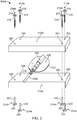
- Figure 2 shows an exploded view of the first (anodal) electrode assembly 104a from Figure 1
- the illustrated assembly 104a includes an upper substantially porous element, in the form of upper sponge 210a, a lower substantially porous element in the form of lower sponge 210b, an electrode 212 between the upper and lower sponges 210a, 210b and an electrical cable coupled to the electrode 212.
- the illustrated assembly 104a also includes a plurality of insulating members, in the form of rivets 214a/214b that are coupled to the upper and lower sponges 210a, 210b.
- Each rivet 214a/214b has an upper portion 214a with a head 216 and a shaft 218 and a lower portion 214b with a head 220 and a shaft 222.
- the upper and lower sponges 210a, 210b are electrode sponges, particularly adapted for use in connection with neurostimualtion procedures, such as tDCS.
- the upper and lower sponges 210a, 210b are adapted to receive and contain an electrolytic solution to facilitate conduction during the procedure.
- the rivets in contrast, are typically rigid elements that are not electrically conductive or at least have substantially lower conductivity than the sponges saturated with electrolyte.
- the rivets are typically electrically insulating.
- Some suitable materials for the rivets include glass, Teflon, rubber, plastics, a conductive material that is at least partially covered with an insulating layer, etc.
- the aligned shafts 218, 222 pass through the upper and lower sponges 210a, 210b to engage one another and hold the upper and lower sponges 210a, 210b together.
- the upper and lower sponges 210a, 210b are held together in such a manner that a human operator can easily slide an electrode (e.g., electrode 212) in between the upper and lower sponges 210a, 210b.
- the upper and lower sponges 210a, 210b are held together in such a manner that they can grip an electrode (e.g., electrode 212) positioned in between the upper and lower sponges 210a, 210b.
- the upper rivet heads 216 are exposed at an outer surface (facing upward in Figure 2 ) of the upper sponge 210a and the lower rivet heads 220 are exposed at an outer surface (not visible, but facing downward in Figure 2 ) of the lower sponge 210b.
- at least a portion of the outer surface (not visible, but facing downward in Figure 2 ) of the lower sponge 210b would be positioned in physical contact with the skin (or skin and hair) of the human patient. Indeed, in most implementations, the entire outer surface of the lower sponge 210b, including the lower rivet heads, come into contact with the patient's skin during tDCS.
- the rivets and, particularly, the lower rivet heads exposed at the outer surface of the lower substantially porous material help reduce the likelihood that a person receiving tDCS (or other types of neurostimulation) will experience discomfort. It is believed that this is generally due to a redistribution of electrical current flowing out of the bottom surface of the lower sponge that results from the exposed head of the non-conductive rivets at that surface.
- the rivet heads 216, 220 are flat or at least substantially flat and, therefore, lie substantially in (or extend only slight out of) the planes associated with the outer surfaces of the upper and lower sponges 210a, 210b.
- the electrode 212 includes a flat, substantially disk-shaped portion 228 that may be, for example, an electrically conductive silicon rubber material, or the like.
- the disk-shaped portion has a substantially flat bottom surface 230 that comes into intimate contact with at least a portion of the lower sponge 210b when assembled.
- the disk-shaped portion has a plug connection 232 at its upper surface that provides an electrical socket adapted to receive and engage the electrical cable 102a that delivers electrical current from the tDCS device 100 both physically and electrically.
- electrical current flows into the electrode 212 from the electrical cable 102a and flows from the disk-shaped portion 228 into the lower sponge 210b to the patient.
- FIGS 3A and 3B are perspective views showing the electrode 212 of Figure 2 being slid between a preassembled electrode interface device 340 that includes the upper and lower sponges 210a, 210b held together by rivets 214a/214b, as represented in Figure 2 .
- the electrode 212 is inserted far enough into the space between the upper and lower sponges 210a, 210b that the entire flat bottom surface of the disk-shaped portion 228 of the electrode 212 is able to contact the inner surface of the lower substantially porous material 210b.
- the rivets 214a/214b are placed far enough away from one another that the electrode 212 can be slid between the upper and lower sponges 210a, 210b.
- FIGS 4A to Figure 4E are bottom views of an electrode interface device (e.g., 340 in Fig. 3A ) showing a variety of possible configurations for the lower sponge 210b and the lower rivet heads 220 exposed at the outer surface thereof.
- an electrode interface device e.g., 340 in Fig. 3A
- Figures 4A to Figure 4E are bottom views of an electrode interface device (e.g., 340 in Fig. 3A ) showing a variety of possible configurations for the lower sponge 210b and the lower rivet heads 220 exposed at the outer surface thereof.
- an electrode interface device e.g., 340 in Fig. 3A
- Figures 4A to Figure 4E are bottom views of an electrode interface device (e.g., 340 in Fig. 3A ) showing a variety of possible configurations for the lower sponge 210b and the lower rivet heads 220 exposed at the outer surface thereof.
- a variety of other configurations are possible as well.
- the bottom surface (i.e., the "contact surface") of the lower sponge 210b is substantially rectangular but with rounded corners.
- the lower sponge 210b has an edge that extends from the bottom surface (into the page) and defines an outer perimeter of the sponge.
- each rivet head being proximate one of the rounded corners of the bottom surface.
- the exposed rivet heads 220 are relatively close to, but usually not touching or overlapping the closest edge (or corner) of the bottom surface.
- the outermost points of the exposed rivets heads are no further from the nearest edge of the bottom surface than approximately 50% of the width of the rivet head.
- the center of the rivet head is between about 0.5 centimeters and 1.6 centimeters from the nearest edge or edges of the bottom surface of the sponge. In some implementations, the center of the rivet head is between about 0.5 centimeters and 1.6 centimeters from the nearest edge of another rivet, too.
- the rivet heads 220 in Figure 4A are arranged in a substantially symmetrical manner about the bottom surface of the sponge 210b. Other, non-symmetrical arrangements are possible as well.
- the configuration in Figure 4B is similar to the configuration in Figure 4A except that the sponge 210b in Figure 4B has a corner at each point where the bottom surface (the "contact surface") and two of the side edges connect to one another. Therefore, the contact surface has four corners and the rivet heads are exposed at the contact surface near each corner.
- the configuration in Figure 4C is similar to the configuration in Figure 4B except that the corners of the rectangular lower sponge 210b have been cut off along a straight line. Also, the exposed lower rivet heads 220 are very close or overlapping the cut off straight edges at each corner.
- the configuration in Figure 4D is similar to the configuration in Figure 4B except that the corners of the rectangular lower sponge 210b have been cut off to form a concave edge at each corner.
- the configuration in Figure 4E is similar to the configuration in Figure 4B except that there is an additional lower rivet head 220 exposed at a center of the bottom surface of the sponge 210b.
- This arrangement may be beneficial if, for example, the assembly is particularly long (with length extending in the horizontal direction in Figure 4E ). In such cases, the middle rivet may enhance the structural integrity of the device, particularly across the middle portion of the device.
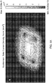
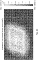
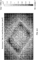
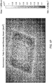
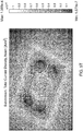
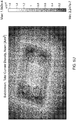
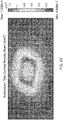
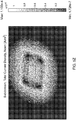
- Table 1 indicates a name assigned to that model, the maximum simulated current density at any given spot on the contact surface of the corresponding simulated electrode assembly, the location of the maximum current density, the distance in centimeters from the rivet's axis to the closest edge of the sponge, the sponge shape, the sponge thickness and the corresponding one of Figures 5A-5AB , which provides a visual representation of the modeled electrode assembly.
- Each of Figures 5A-5AB show visual representations of modeled electrode assemblies.
- Each modeled electrode assembly shows sponges and an electrode (represented by a square shape approximately centrally located relative to the sponges). Also, some of the visual representations also show rivets.
- Each of the visual representations include shading of varying degree that represents different current densities passing through the bottom surface of the lower electrode into a patient.
- a scale is provided at the right side of each figure identifying the current density that each different shade in the model represents. In Figure 5A , for example, the scale on the right of the figure goes from 9.063 x 10 -10 A/m 2 up to 6.236 x 10 -5 A/m 2 .
- a visual inspection of the modeled electrode assembly reveals that the highest current density according to this model can be expected around the center of the bottom sponge, whereas the lowest current density occurs at the rivets, which are non-conductive.
- the thicker the sponge probably up to some limit, the greater the likelihood is that electrical current emanating from the electrode will extend out near the edges of the sponge and pass into the patient near the sponge's perimeter.
- the thickness of the bottom sponge is between about 0.5 centimeters and 2 centimeters.
- the resistivity or salinity of the sponge influences current dispersion in a similar manner to sponge thickness.
- High resistivity sponge properties act similar to thinner sponges, while low resistivity sponges act similar to thicker sponges.
- sponge with a lower thickness and lower resistivity can function like a sponge with higher thickness and higher resistivity.
- decreasing resistivity may increase performance.
- decreasing resistivity to a still lower value may be undesired as it results in an extreme concentration of current at sponge edges.
- the properties of the sponge may be controlled in a number of ways.
- the salt content of the electrolyte in the sponge can be increased to decrease resistivity or decreased to increase resistivity.
- the primary anion salt may be sodium or calcium, or a combination of the two ions.
- Salinity close to saline or cerebrospinal fluid is preferred but may be increased or decreased by 50%.
- the porosity of the sponge may be controlled. Increasing pore size or the density of pores will typically increase conductivity of the sponge. Porosity factors effecting resistivity may be compensated for by adjusting salinity as described.
- the electrically insulated rivets may improve the distribution of electrical current flowing out of the contact surface of the sponge by reducing the maximum current density that occurs at the contact surface and/or by facilitating a more even distribution of electrical current density across the contact surface.
- the beneficial effects that the rivets provide in facilitating a reduction in maximum current density and providing a more even distribution of current across the contact surface are particularly prominent when the outermost edge of the electrode is between about 0.5 centimeters and about 1.6 centimeters from a closest edge of the sponge's bottom surface. Therefore, in such instances, a portion of the substantially porous material is exposed at the contact surface between the exposed portion of the first insulating member and edge of the first insulating member that is closest to the exposed portion.
- Figures 6A-6C show a preassembled electrode interface device 640 that includes upper and lower sponges 610a, 610b held together by rivets 614a/614b and connected to a strap 660.
- the electrode interface device 640 is supported by the strap by virtue of the strap passing between the upper rivet heads and the upper surface of the upper sponge 610a.
- the strap can form any part of a device or cap or the like to hold the electrode interface device 640 and other such devices in place against a patient's skin.
- a space 662 is provided between the upper and lower sponges 610a, 610b to receive an electrode.
- only one of the electrode assemblies (e.g., the anodal electrode) in a system will include a rivet or rivets.
- the rivet or rivets only pass through the bottom sponge or bottom portion of a sponge in an electrode assembly. In those instances, the rivets play no role in holding components together, but still provide benefits as discussed herein.
- the rivets and their constituent parts can have a variety of shapes and sizes. Any number and arrangement of rivets can be provided.
- the holes that the rivets pass through in the sponge(s) may be pre-formed or may be formed simply by virtue of the shaft portions of the rivets being pushed through the sponge(s).
- the electrodes can take a variety of shapes and sizes. They need not be flat, and can be hardwired to the electrical cable that connects to the tDCS device. They also can be permanently connected to the electrode interface assembly.
- the upper sponge and the lower sponge may actually be simply two parts of the same sponge, separated, for example, by an opening in an edge of the sponge for receiving and gripping the electrode in a manner that facilitates a low resistance electrical connection between the sponge and the electrode.
- both electrodes need not be positioned on the patient's head to deliver effective tDCS. Instead, for example, one can be positioned on the patient's head and the other on the patient's neck. Instead of rivets, the insulating members can be a pin pushed into the contact surface of the substantially porous element, a sticker or adhesive material adhered to the contact surface of the substantially porous element.
- the insulating portion such as the rivets
- the surface of the rivet may slightly protrude from sponge surface.
- the distance of protrusion should not be so much that a significant portion of the sponge is prevented from touching the body or target surface as a result of the protrusion.
- the protrusion may be up to about 0.5 cm or 0.1 cm.
- the surface of the protrusion may be concave or bent.
- the protruding surface generally has a sufficiently large area such that then the sponge is applied with a typical amount of pressure, for example, as may be provided by a strap, then at least some fluid is ejected from the sponge forming a thin layer between the sponge and the tissue, but the form of the insulator acts to minimize or control the level of fluid between the insulator and the tissue. For example, there may be no significant fluid between the insulator and the tissue.
- the sponge or strap may include a mechanism to control or indicate the level of force or pressure applied to the electrode.
- a tightening mechanism on a strap may be adjusted to provide a preferred amount of force or pressure on the electrode.
- the tightening mechanism or a separate mechanism may provide a direct or indirect indication of the pressure or force.
- the tightening mechanism may control the level of pressure or force applied for example by releasing tightness when a level is exceeded.
Description
- This disclosure relates to an electrode assembly and also systems and methods for delivering neurostimulation, such as transcranial direct current stimulation ("tDCS") to a patient, using the electrode assembly.
- Neurostimulation involves modulating the nervous system and electrically activating neurons in the body. Transcranial direct current stimulation (tDCS) is a form of neurostimulation that uses constant, low current delivered directly to particular areas of the brain using electrodes. tDCS can be used, for example, as therapy for certain psychological disorders, such as anxiety disorders and depression.
FR 2 452 938 - In one aspect, an electrode assembly includes a substantially porous element configured to be coupled to an electrode for delivery of electrical current to a patient in a neurostimulation procedure. The substantially porous material defines a contact surface, at least a portion of which contacts the patient during the neurostimulation procedure. A first insulating member (e.g., a rivet) is coupled to the substantially porous element and exposed at the contact surface to prevent a portion of the contact surface from contacting the patient to deliver the electrical current during the neurostimulation procedure.
- In some implementations, the substantially porous element has one or more edges that extend from the contact surface. In those implementations, the first insulating member is exposed at the contact surface near one of the edges. In certain embodiments, the first insulating member is positioned so that an outermost point of the exposed portion is no further from the nearest edge than approximately 50% of the exposed portion's width.
- The substantially porous element, in some embodiments, has a corner at a point where the contact surface and two of the edges connect to one another and the first insulating member is exposed at the contact surface near the corner.
- According to certain implementations, the substantially porous element has one or more edges at which an opening is provided for receiving and gripping the electrode in a manner that facilitates a low resistance electrical connection between the substantially porous element and the electrode.
- A portion of the substantially porous material can be exposed at the contact surface between the exposed portion of the first insulating member and edge of the first insulating member that is closest to the exposed portion.
- In certain embodiments, the substantially porous element includes a first portion and a second portion. The first insulating member is configured to physically hold together the first portion and the second portion. In some instances, the first insulating member includes a substantially cylindrical portion (that may or may not include two portions joined together) that extends through the first and second portions of the substantially porous member and a head at each end of the substantially cylindrical portion, wherein each head has a larger diameter than the substantially cylindrical portion.
- The first insulating member can be, for example, a rivet, a pin pushed into the contact surface of the substantially porous element or a sticker or adhesive material adhered to the contact surface of the substantially porous element.
- In some implementations, the substantially porous material is configured to absorb and at least partially contain an electrolyte in liquid form.
- In a typical embodiment, a second insulating member is coupled to the substantially porous element and exposed at the contact surface. The first and second insulating members are spaced sufficiently far apart from one another so that the electrode can fit between the first and second insulating members.
- In another aspect, an electrode assembly includes a substantially porous element having a contact surface, at least a portion of which is configured to contact a patient during delivery of electrical current from the substantially porous element to the patient during a neurostimulation procedure, wherein the substantially porous element includes a first portion and a second portion. Two or more rivets are provided that are made of electrically insulating material and that pass through the first portion and second portion of the substantially porous element to hold the first and second portion together. Each rivet has a head portion exposed at the contact surface to prevent a portion of the contact surface from contacting the patient during the neurostimulation procedure. The rivets are positioned so that an innermost portion of each respective head is no further from a closest edge of the substantially porous element than approximately 150% of the head's diameter.
- In yet another aspect, a system includes a neurostimulation device (e.g., a tDCS device), at least two electrically conductive cables coupled to the neurostimulation device; an electrode coupled to the distal end of each respective one of the electrically conductive cables; and an electrode interface optionally removably coupled to at least one of the electrodes. Each electrode interface includes a substantially porous element physically coupled to the electrode for delivery of electrical current to a patient in a neurostimulation procedure. The substantially porous material defines a contact surface. At least a portion of the contact surface contacts the patient during the neurostimulation procedure. A first insulating member is coupled to the substantially porous element and exposed at the contact surface to prevent a portion of the contact surface from contacting the patient to deliver the electrical current during the neurostimulation procedure.
- In some implementations, the substantially porous element has one or more edges that extend from the contact surface, and the first insulating member is positioned so that an outermost point of the exposed portion is no further from the nearest edge than approximately 50% of the exposed portion's width.
- The substantially porous element typically has a corner at a point where the contact surface and two of the edges connect to one another and the first insulating member is exposed at the contact surface near the corner. According to certain embodiments, the substantially porous element has one or more edges at which an opening is provided for receiving and gripping the electrode in a manner that facilitates a low resistance electrical connection between the substantially porous element and the electrode.
- A portion of the substantially porous material typically is exposed at the contact surface between the exposed portion of the first insulating member and edge of the first insulating member that is closest to the exposed portion.
- In some implementations, the substantially porous element has a first portion and a second portion. The first insulating member is configured to physically hold together the first portion and the second portion and the electrode is positioned between the first portion and the second portion of the substantially porous element.
- The first insulating member can be a rivet with a substantially cylindrical portion that extends through the first and second portions of the substantially porous member and a head at each end of the substantially cylindrical portion. Each head typically has a larger diameter than the substantially cylindrical portion.
- In certain embodiments, a second insulating member is coupled to the substantially porous element and exposed at the contact surface. The first and second insulating members are spaced sufficiently far apart from one another so as to accommodate the electrode, which is positioned between the first and second insulating members.
- According to some implementations, a second insulating member is coupled to the substantially porous element and exposed at the contact surface. The first and second insulating members are exposed at a surface of the substantially porous material opposite the contact surface. In those instances, the system further includes a strap for coupling the electrode interface to the patient. The strap can be, for example, between portions of the first and second insulating members that are exposed at the surface of the substantially porous material opposite the contact surface and the portions of the first and second insulating members extend over the strap to thereby couple the electrode interface to the strap.
- The first insulating member can be, for example, a pin pushed into the contact surface of the substantially porous element or a sticker or adhesive material adhered to the contact surface of the substantially porous element.
- The substantially porous material is adapted to and typically does contain an electrolyte in liquid form during the delivery of electrical current.
- In some implementations, for electrodes greater than 5 cm2, for electrolytes with resistivity more than triple of saline solution, or when a porous material (sponge) density is used, or small pore size, or large inter-pore distance is present, such that the resulting resistivity of the sponge is more than triple that of saline solution, then it may be desirable to increase the porous material thickness between the electrode and the skin to about 0.75 cm (i.e., three times 0.25 cm).
- In a typical implementation, the conductive rubber insert (of the electrode), when used in a sponge pocket, is greater than about 1 cm2 and preferably greater than about 4 cm2. An increase area of the rubber inset facilitates greater dispersion of current prior to reaching the skin. For sponge thickness of less than about 0.5 cm, the size of the rubber inset or other electrode can be increased in area such that, in some instances, the distance from the edge of the rubber inset to the edge of the sponge pocket is less than about 1 cm. This can, in certain implementations, facilitate current reaching sponge edges including when higher resistivity porous material is used.
- According to certain embodiments, the conductive rubber inset is not insulated on either surface such that current may exit from the rubber inset into both the top and bottom porous material which may, in some instances, enhance the spread of current toward the electrode edges. For this reason, the presence of a porous material with electrolyte over the rubber inset allows for current to exit from the top surface of the sponge. In some instances, it may be desirable for the thickness of the porous material over the rubber inset to be greater than about 0.25 cm and preferably greater than about 0.5 cm. The thickness of the top porous material can be less than then bottom porous material. Using a thinner top porous material, in some instances, reduces the overall thickness of the sponge.
- The conductive rubber inset may be replaced with a metal material where the metal material has a largely planar structure preferably allowing it to be placed on the surface of one of the porous materials. If the exposed area of the metal is less than about 2cm2, and especially if is less than about 1 cm2, then, in some instances, more than one conductor may be inserted into the sponges thus effectively increasing the total area of metal contacting the sponge to the combined area of the metal electrodes. For example, 4 electrodes of approximately 1cm2 can be positioned in one sponge and arranged such a line drawn between the centers of the electrode approximates a 4 cm x 4 cm square. Preferably, sintered silver-chloride is used for the metal electrode, or gold, of platinum.
- The average size of pores on the porous material can range from about 80 microns to about 200 microns giving flexibility in the electrolyte uptake by the material. On average, the volumetric expansion of the sponges can be about 0.15 cm3; that is about 0.5 cm on the base (length), about 0.5 cm on the width, and about 6% (0.6 cm) on the thickness.
- As an example, the porous material can be made, for example, from polyvinyl alcohol (PVA) and Glycerin. The porous material may contain reinforcing fibers (threads) that enhance certain mechanical properties of the material and its durability.
- In some implementations, one or more of the following advantages are present. For example, a structurally sound, low pain electrode assembly can be produced.
- Other features and advantages will be apparent from the description and drawings, and from the claims.
-
-
FIG. 1 is a perspective view of a transcranial direct current stimulation ("tDCS") system coupled to a patient. -
FIG. 2 is an exploded view of an electrode assembly in the tDCS system ofFIG. 1 . -
FIGS. 3A and 3B are perspective views of an electrode being pushed between sponges in an electrode interface device. -
FIGS. 4A to 4E are bottom views of electrode assemblies showing different rivet configurations. -
FIGS. 5A to 5AB are representations of computer models of different electrode assembly configurations. -
FIG. 6A to 6C are views of an electrode assembly coupled to a strap for coupling to a patient. - Like reference characters in the drawings refer to like elements.
- The present application relates to an electrode assembly and systems and methods for delivering neurostimulation, such as transcranial direct current stimulation ("tDCS") to a patient, using the electrode assembly.
- In general, tDCS uses a relatively constant, low flow of direct electrical current delivered directly to the brain area of a patient using small electrodes placed on the patient's skin (i.e., not directly on the patient's brain). More particularly, when the electrodes are placed in or near the regions of interest, electrical current flow through the electrodes induces intracerebral current flow. This intracerebral current flow can either increase or decrease neuronal excitability in specific areas being stimulated based on which type of stimulation is being used. This change of neuronal excitability leads to alteration of brain function, which can be used in various therapies as well as to provide more information about the functioning of the human brain. For example, tDCS can be used as therapy for certain physicological disorders, such as anxiety disorders and depression, as well as a tool for motor rehabilitation in stroke patients.
- The neurostimulation and tDCS techniques disclosed herein are completely noninvasive and, therefore, easy to administer, safe and convenient for patients or recipients of the tDCS.
-
Figure 1 shows anexemplary tDCS device 100 connected via a pair ofelectrical cables electrode assemblies human patient 106. There are a variety of ways that theelectrode assemblies electrode assemblies 104a is positioned near a front portion of the patient's head and a second one of theelectrode assemblies 104b is positioned back on the top of the patient's head, displaced at least several centimeters away from thefirst electrode 104a. Of course, a variety of electrode configurations are possible. - In a typical implementation, before the actual tDCS is initiated, a human operator would program into the
tDCS device 100 at least: 1) a target value of current; and 2) a duration for delivering the target value of current to thehuman patient 106. Prior to delivery of current, the human operator positions the electrodes, prepares them (e.g., by adding fluid, such as an electrolyte) and/or checking the resistance of the electrode connections to the patient - If all is in order, then, the human operator prompts the
tDCS device 100 to begin producing electrical current. In response to this prompt (or in response to some other external trigger), thetDCS device 100 begins producing electrical current. More particularly, in response to the prompt from the human operator, thetDCS device 100 ramps the flow of electrical current from zero up to the target current value, delivers the target current value for approximately the duration that was specified by the human operator, and then ramps the flow of electrical current back to zero. In one implementation, while electrical current is being produced, it flows from thetDCS device 100 to thehuman patient 106 via theelectrical cable 102a and thefirst electrode assembly 104a (the anodal electrode assembly) and returns to thetDCS device 100 via thesecond electrode assembly 104b (the cathodal electrode assembly) and the secondelectrical cable 102b. - In general, electrical current flow produces heat. In some implementations, when electrical current is being delivered to a patient during transcranial direct current stimulation, or the like, heat produced at the interface of the
electrode assemblies patient 106 to experience an often high degree of discomfort while the electrical current is flowing. In the illustrated implementation, theelectrode assemblies -
Figure 2 shows an exploded view of the first (anodal)electrode assembly 104a fromFigure 1 - The illustrated
assembly 104a includes an upper substantially porous element, in the form ofupper sponge 210a, a lower substantially porous element in the form oflower sponge 210b, anelectrode 212 between the upper andlower sponges electrode 212. The illustratedassembly 104a also includes a plurality of insulating members, in the form ofrivets 214a/214b that are coupled to the upper andlower sponges rivet 214a/214b has anupper portion 214a with ahead 216 and ashaft 218 and alower portion 214b with ahead 220 and ashaft 222. - In a typical implementation, the upper and
lower sponges lower sponges - The rivets are typically electrically insulating. Some suitable materials for the rivets include glass, Teflon, rubber, plastics, a conductive material that is at least partially covered with an insulating layer, etc.
- When the
electrode assembly 104a is assembled, the alignedshafts lower sponges lower sponges lower sponges lower sponges lower sponges lower sponges - When the
electrode assembly 104a is assembled, the upper rivet heads 216 are exposed at an outer surface (facing upward inFigure 2 ) of theupper sponge 210a and the lower rivet heads 220 are exposed at an outer surface (not visible, but facing downward inFigure 2 ) of thelower sponge 210b. In a typical implementation, to deliver tDCS to a patient, at least a portion of the outer surface (not visible, but facing downward inFigure 2 ) of thelower sponge 210b (including the lower rivet heads 220) would be positioned in physical contact with the skin (or skin and hair) of the human patient. Indeed, in most implementations, the entire outer surface of thelower sponge 210b, including the lower rivet heads, come into contact with the patient's skin during tDCS. - As discussed in further detail herein, in a typical implementation, the rivets and, particularly, the lower rivet heads exposed at the outer surface of the lower substantially porous material, help reduce the likelihood that a person receiving tDCS (or other types of neurostimulation) will experience discomfort. It is believed that this is generally due to a redistribution of electrical current flowing out of the bottom surface of the lower sponge that results from the exposed head of the non-conductive rivets at that surface.
- In a typical implementation, the rivet heads 216, 220 are flat or at least substantially flat and, therefore, lie substantially in (or extend only slight out of) the planes associated with the outer surfaces of the upper and
lower sponges - In the illustrated embodiment, the
electrode 212 includes a flat, substantially disk-shapedportion 228 that may be, for example, an electrically conductive silicon rubber material, or the like. The disk-shaped portion has a substantially flatbottom surface 230 that comes into intimate contact with at least a portion of thelower sponge 210b when assembled. The disk-shaped portion has aplug connection 232 at its upper surface that provides an electrical socket adapted to receive and engage theelectrical cable 102a that delivers electrical current from thetDCS device 100 both physically and electrically. - During operation, electrical current flows into the
electrode 212 from theelectrical cable 102a and flows from the disk-shapedportion 228 into thelower sponge 210b to the patient. -
Figures 3A and 3B are perspective views showing theelectrode 212 ofFigure 2 being slid between a preassembledelectrode interface device 340 that includes the upper andlower sponges rivets 214a/214b, as represented inFigure 2 . - In the illustrated implementation, it can be seen that the
electrode 212 is inserted far enough into the space between the upper andlower sponges portion 228 of theelectrode 212 is able to contact the inner surface of the lower substantiallyporous material 210b. In the illustrated implementation, it can also be seen that therivets 214a/214b are placed far enough away from one another that theelectrode 212 can be slid between the upper andlower sponges -
Figures 4A to Figure 4E are bottom views of an electrode interface device (e.g., 340 inFig. 3A ) showing a variety of possible configurations for thelower sponge 210b and the lower rivet heads 220 exposed at the outer surface thereof. Of course, a variety of other configurations are possible as well. - In
Figure 4A , for example, the bottom surface (i.e., the "contact surface") of thelower sponge 210b is substantially rectangular but with rounded corners. In the illustrated implementation, thelower sponge 210b has an edge that extends from the bottom surface (into the page) and defines an outer perimeter of the sponge. - There are four lower rivet heads 220 exposed at the bottom surface of the
lower sponge 210b, each rivet head being proximate one of the rounded corners of the bottom surface. In a typical implementation, the exposed rivet heads 220 are relatively close to, but usually not touching or overlapping the closest edge (or corner) of the bottom surface. For example, in some implementations and, as shown inFigure 4A , the outermost points of the exposed rivets heads are no further from the nearest edge of the bottom surface than approximately 50% of the width of the rivet head. In some implementations, the center of the rivet head is between about 0.5 centimeters and 1.6 centimeters from the nearest edge or edges of the bottom surface of the sponge. In some implementations, the center of the rivet head is between about 0.5 centimeters and 1.6 centimeters from the nearest edge of another rivet, too. - The rivet heads 220 in
Figure 4A are arranged in a substantially symmetrical manner about the bottom surface of thesponge 210b. Other, non-symmetrical arrangements are possible as well. - The configuration in
Figure 4B is similar to the configuration inFigure 4A except that thesponge 210b inFigure 4B has a corner at each point where the bottom surface (the "contact surface") and two of the side edges connect to one another. Therefore, the contact surface has four corners and the rivet heads are exposed at the contact surface near each corner. - The configuration in
Figure 4C is similar to the configuration inFigure 4B except that the corners of the rectangularlower sponge 210b have been cut off along a straight line. Also, the exposed lower rivet heads 220 are very close or overlapping the cut off straight edges at each corner. - The configuration in
Figure 4D is similar to the configuration inFigure 4B except that the corners of the rectangularlower sponge 210b have been cut off to form a concave edge at each corner. - The configuration in
Figure 4E is similar to the configuration inFigure 4B except that there is an additionallower rivet head 220 exposed at a center of the bottom surface of thesponge 210b. This arrangement may be beneficial if, for example, the assembly is particularly long (with length extending in the horizontal direction inFigure 4E ). In such cases, the middle rivet may enhance the structural integrity of the device, particularly across the middle portion of the device. - A number of models were developed to examine how the insulated rivets influence the electrical current flow out of the bottom surface (i.e., the "contact surface") of the bottom sponge in an electrode assembly. Some of the results of the modeling are shown below in Table 1 (below), which cross-references
Figures 5A-5AB as indicated in the table.Table 1 Name Max Current Density (A/m^2) Max Current Density Location Rivets Axis Distance from Edges (cm) Sponge Shape Sponge Thickness (cm) Figure NoRivets 5.54E-05 Center None Rectangle 0.5 Fig. 5A NoRivets2 4.26E-05 Mostly Center None Rectangle 0.75 Fig. 5B NoRivets3 4.08E-05 Center/ Edge None Rectangle 1 Fig. 5C NoRivets4 4.58E-05 Mostly Edge None Rectangle 1.25 Fig. 5D NoRivets5 3.79E-05 Edge None Rectangle 1.5 Fig. 5E LayeredNoRivets 8.65E-05 Center/Edge None Rectangle 0.25 Fig. 5F LayeredNoRivets2 7.25E-05 Edge None Rectangle 0.5 Fig. 5G LayeredRivets 1.56E-04 Rivets 1.5 Rectangle 0.25 Fig. 5H LayeredRivets2 7.36E-05 Edges/Rivets 1.5 Rectangle 0.5 Fig. 5I LayeredRivets3 9.95E-05 Edges/Rivets 1.1 Rectangle 0.25 Fig. 5J LayeredRivets4 9.07E-05 Edges/Rivets 1.1 Rectangle 0.5 Fig. 5K LayeredRivets5 1.24E-04 Edges/Rivets On Corners Rectangle 0.5 LayeredRivets6 1.76E-04 Center/Edge /Rivets On Corners Rectangle 0.25 LayeredRivets7 1.07E-04 Edge 0.9 Rectangle 0.5 LayeredRivets8 9.91E-05 Center/Edge /Rivets 0.9 Rectangle 0.25 Fig. 5L LayeredRivets9 9.09E-05 Edge 1.1 Rectangle 0.5 Fig. 5M LayeredRivets10 9.27E-05 Center/Edge /Rivets 1.1 Rectangle 0.25 Fig. 5N LayeredRivets11 8.57E-05 Edges/Rivets 1.3 Rectangle 0.5 Fig. 5O LayeredRivets12 1.09E-04 Rivets 1.3 Rectangle 0.25 Fig. 5P LayeredRivets13 7.36E-05 Edges/Rivets 1.5 Rectangle 0.5 Fig. 5Q LayeredRivets14 1.50E-04 Rivets 1.5 Rectangle 0.25 Fig. 5R LayeredRivets15 7.24E-05 Edges/Rivets 1.6 Rectangle 0.5 LayeredRivets16 1.59E-04 Rivets 1.6 Rectangle 0.25 Fig. 5S LayeredRivets17 1.07E-04 Rivets 1.7 Rectangle 0.5 Fig. 5T LayeredRivets18 1.64E-04 Rivets 1.7 Rectangle 0.25 Fig. 5U LayeredRivets19 8.16E-05 Edges/Rivets x: 1.6, z:1.5 Rectangle 0.5 Fig. 5V LayeredRivets2 0 1.78E-04 Edges of saline layer 1.6 Rectangle 0.5 Fig. 5W RoundLayered NoRivets 1.23E-04 Edge None Rounded Edges 0.5 Fig. 5X RoundLayered Rivets1 1.03E-04 Corners 1.6 Rounded Edges 0.5 Fig. 5Y RoundLayered Rivets2 1.10E-04 Corners 1.1 Rounded Edges 0.5 Fig. 5Z RoundLayered Rivets3 1.08E-04 Corners 0.6 Rounded Edges 0.5 Fig. 5AA RoundLayered Rivets4 1.05E-04 Corners 0.4 Rounded Edges 0.5 Fig. 5AB - The total current being delivered by the modeled electrode assembly was about 1 milliamp in each instance. For each model, Table 1 indicates a name assigned to that model, the maximum simulated current density at any given spot on the contact surface of the corresponding simulated electrode assembly, the location of the maximum current density, the distance in centimeters from the rivet's axis to the closest edge of the sponge, the sponge shape, the sponge thickness and the corresponding one of
Figures 5A-5AB , which provides a visual representation of the modeled electrode assembly. - Each of
Figures 5A-5AB show visual representations of modeled electrode assemblies. Each modeled electrode assembly shows sponges and an electrode (represented by a square shape approximately centrally located relative to the sponges). Also, some of the visual representations also show rivets. - Each of the visual representations include shading of varying degree that represents different current densities passing through the bottom surface of the lower electrode into a patient. A scale is provided at the right side of each figure identifying the current density that each different shade in the model represents. In
Figure 5A , for example, the scale on the right of the figure goes from 9.063 x 10⁻¹⁰ A/m2 up to 6.236 x 10⁻⁵ A/m2. A visual inspection of the modeled electrode assembly reveals that the highest current density according to this model can be expected around the center of the bottom sponge, whereas the lowest current density occurs at the rivets, which are non-conductive. - There are a several noteworthy observations, some of which can find support in the data in Table 1 and in
Figures 5A-5AB . - For example, in general the thicker the sponge, probably up to some limit, the greater the likelihood is that electrical current emanating from the electrode will extend out near the edges of the sponge and pass into the patient near the sponge's perimeter. In some implementations, therefore, it appears possible to control or at least influence the current density at different points along the contact surface of the electrode assembly by modifying the thickness of the bottom sponge in the assembly. In some implementations, the thickness of the bottom sponge is between about 0.5 centimeters and 2 centimeters.
- The resistivity or salinity of the sponge influences current dispersion in a similar manner to sponge thickness. High resistivity sponge properties act similar to thinner sponges, while low resistivity sponges act similar to thicker sponges. In this way, sponge with a lower thickness and lower resistivity can function like a sponge with higher thickness and higher resistivity. Thus decreasing resistivity may increase performance. In some implementations, decreasing resistivity to a still lower value may be undesired as it results in an extreme concentration of current at sponge edges.
- The properties of the sponge, including resistivity, may be controlled in a number of ways. For example, the salt content of the electrolyte in the sponge can be increased to decrease resistivity or decreased to increase resistivity. The primary anion salt may be sodium or calcium, or a combination of the two ions. Salinity close to saline or cerebrospinal fluid is preferred but may be increased or decreased by 50%. The porosity of the sponge may be controlled. Increasing pore size or the density of pores will typically increase conductivity of the sponge. Porosity factors effecting resistivity may be compensated for by adjusting salinity as described.
- Additionally, depending on other parameters, the electrically insulated rivets may improve the distribution of electrical current flowing out of the contact surface of the sponge by reducing the maximum current density that occurs at the contact surface and/or by facilitating a more even distribution of electrical current density across the contact surface.
- Moreover, in thinner sponges (e.g., 0.25 centimeters thick), current from a centrally disposed electrode tends to pass through the bottom surface of the sponge mostly near the center of the sponge, with very little to no current passing through the contact surface near the outer perimeter of the surface. In those instances, adding rivets near the edges of the sponge seems to draw the current out from the middle and toward the perimetral edges of the sponge. In some instances, this can result in a reduction in maximum current density through the contact surface at any one point and can result in a more even distribution of current through the contact surface.
- On the other hand, in thicker sponges (e.g., 0.5 centimeters thick), current tends to reach the perimetral edges of the sponge somewhat naturally without the insulating rivets. In those instances, adding insulating rivets appears to be able to block some of the current flowing toward the perimetral edges and directing it out of the sponge in a more centrally located spot on the contact surface. In some instances, this can result in a reduction in maximum current density through the contact surface at any one point and can result in a more even distribution of current through the contact surface.
- Additionally, in a typical implementation, the beneficial effects that the rivets provide in facilitating a reduction in maximum current density and providing a more even distribution of current across the contact surface are particularly prominent when the outermost edge of the electrode is between about 0.5 centimeters and about 1.6 centimeters from a closest edge of the sponge's bottom surface. Therefore, in such instances, a portion of the substantially porous material is exposed at the contact surface between the exposed portion of the first insulating member and edge of the first insulating member that is closest to the exposed portion.
-
Figures 6A-6C show a preassembledelectrode interface device 640 that includes upper andlower sponges rivets 614a/614b and connected to astrap 660. Theelectrode interface device 640 is supported by the strap by virtue of the strap passing between the upper rivet heads and the upper surface of theupper sponge 610a. The strap can form any part of a device or cap or the like to hold theelectrode interface device 640 and other such devices in place against a patient's skin. Aspace 662 is provided between the upper andlower sponges - A number of embodiments have been described. Nevertheless, it will be understood that various modifications may be made without departing from the scope of the present description.
- For example, in some implementations, only one of the electrode assemblies (e.g., the anodal electrode) in a system will include a rivet or rivets.
- Additionally, in some implementations, the rivet or rivets only pass through the bottom sponge or bottom portion of a sponge in an electrode assembly. In those instances, the rivets play no role in holding components together, but still provide benefits as discussed herein. The rivets and their constituent parts can have a variety of shapes and sizes. Any number and arrangement of rivets can be provided.
- The holes that the rivets pass through in the sponge(s) may be pre-formed or may be formed simply by virtue of the shaft portions of the rivets being pushed through the sponge(s).
- The electrodes can take a variety of shapes and sizes. They need not be flat, and can be hardwired to the electrical cable that connects to the tDCS device. They also can be permanently connected to the electrode interface assembly. The upper sponge and the lower sponge may actually be simply two parts of the same sponge, separated, for example, by an opening in an edge of the sponge for receiving and gripping the electrode in a manner that facilitates a low resistance electrical connection between the sponge and the electrode.
- In some implementations, both electrodes need not be positioned on the patient's head to deliver effective tDCS. Instead, for example, one can be positioned on the patient's head and the other on the patient's neck. Instead of rivets, the insulating members can be a pin pushed into the contact surface of the substantially porous element, a sticker or adhesive material adhered to the contact surface of the substantially porous element.
- The insulating portion, such as the rivets, can take on various shapes. The surface of the rivet may slightly protrude from sponge surface. In general, the distance of protrusion should not be so much that a significant portion of the sponge is prevented from touching the body or target surface as a result of the protrusion. For example the protrusion may be up to about 0.5 cm or 0.1 cm. In addition, the surface of the protrusion may be concave or bent. The protruding surface generally has a sufficiently large area such that then the sponge is applied with a typical amount of pressure, for example, as may be provided by a strap, then at least some fluid is ejected from the sponge forming a thin layer between the sponge and the tissue, but the form of the insulator acts to minimize or control the level of fluid between the insulator and the tissue. For example, there may be no significant fluid between the insulator and the tissue.
- Application of further pressure to the electrode may cause the sponge to contact the tissue such that there is no significant fluid between the sponge and the tissue. In such case, the insulating portion may press down on the tissue in a manner causing the tissue to deform and a portion of the insulating material to protrude into the tissue. The shape of the protrusion may, in some instances, remove or minimize damage to the tissue. The sponge or strap (e.g., in the form of head-gear) may include a mechanism to control or indicate the level of force or pressure applied to the electrode. For example a tightening mechanism on a strap may be adjusted to provide a preferred amount of force or pressure on the electrode. The tightening mechanism or a separate mechanism may provide a direct or indirect indication of the pressure or force. The tightening mechanism may control the level of pressure or force applied for example by releasing tightness when a level is exceeded.
- The present invention is set out in the appended claims. The embodiments, examples or aspects according to the present description which do not fall within the scope of said claims are provided for illustrative purposes only and do not form part of the present invention.
Claims (8)
- An electrode assembly (104a, 104b) for delivering transcranial direct current stimulation comprising:an electrode (212); a substantially porous element (210a, 210b) configured to be coupled to the electrode (212) for delivery of electrical current to a patient in a neurostimulation procedure, the substantially porous element (210a, 210b) defining a skin contact surface, wherein at least a portion of the contact surface contacts the patient during the neurostimulation procedure;wherein the substantially porous element (210a, 210b) comprises: an upper substantially porous element in the form of upper sponge (210a) and a lower substantially porous element in the form of a lower sponge (210b) which are adapted to receive and contain an electrolytic solution for facilitating electrical conduction, wherein the electrode (212) is between the upper and lower sponges (210a, 210b), the electrode assembly (104a, 104b) further comprising a plurality of insulating members in the form of rivets (214a, 214b) that are coupled to the upper sponge (210a) and to the lower sponge (210b) and which are configured to physically hold together the upper sponge (210a) and the lower sponge (210b), wherein the insulating members (214a, 214b)are exposed at the skin contact surface to prevent a portion of said skin contact surface from contacting the patient to deliver the electrical current during the neurostimulation procedure.
- The electrode assembly (104a, 104b) of claim 1, wherein the the substantially porous element (210a, 210b) has one or more edges that extend from the contact surface, and wherein a first insulating member of the plurality of insulating members (214a, 214b) is exposed at the contact surface near one of the edges.
- The electrode assembly (104a, 104b) of claim 2, wherein the first insulating member (214a, 214b) is positioned so that an outermost point of the exposed portion is no further from the nearest edge than approximately 50% of the exposed portion's width.
- The electrode assembly (104a, 104b) of claim 2, wherein the substantially porous element (210a, 210b) has a corner at a point where the contact surface and two of the edges connect one another and the first insulating member (214a, 214b) is exposed at the contact surface near the corner.
- The electrode assembly (104a, 104b) of claim 1, wherein the upper sponge (210a) and the lower sponge (210b) are two parts of the substantially porous element (210a, 210b), which are separated by an opening in an edge of the sponge for receiving and gripping the electrode.
- The electrode assembly (104a, 104b) of claim 1, wherein the first insulating member (214a, 214b) comprises: a substantially cylindrical portion that extends through the upper sponge (210a) and the lower sponge (210b); and a head (216, 220) at each end of the substantially cylindrical portion, wherein each head has a larger diameter than the substantially cylindrical portion.
- A system for delivering transcranial direct current stimulation comprising: a neurostimulation device (100); at least two electrically conductive cables (102a, 102b) coupled to the neurostimulation device; and an electrode assembly according to any of claims 1 to 6 coupled to the distal end of each respective one of the electrically conductive cables.
- A system for delivering transcranial direct current stimulation comprising: a neurostimulation device (100); at least two electrically conductive cables (102a, 102b) coupled to the neurostimulation device; an electrode assembly according to any of claims 1 to 6 coupled to the distal end of each respective one of the electrically conductive cables; the system further comprising: a strap (660) for coupling the electrode interface to the patient, wherein the strap is between portions of the first and second insulating members that are exposed at the surface of the substantially porous material opposite the contact surface and the portions of the first and second insulating members extend over the strap to thereby couple the electrode interface to the strap.
Applications Claiming Priority (3)
| Application Number | Priority Date | Filing Date | Title |
|---|---|---|---|
| US39463610P | 2010-10-19 | 2010-10-19 | |
| US201161488364P | 2011-05-20 | 2011-05-20 | |
| PCT/US2011/056863 WO2012054587A2 (en) | 2010-10-19 | 2011-10-19 | Electrode assembly |
Publications (3)
| Publication Number | Publication Date |
|---|---|
| EP2629842A2 EP2629842A2 (en) | 2013-08-28 |
| EP2629842A4 EP2629842A4 (en) | 2014-08-27 |
| EP2629842B1 true EP2629842B1 (en) | 2020-09-02 |
Family
ID=45975860
Family Applications (1)
| Application Number | Title | Priority Date | Filing Date |
|---|---|---|---|
| EP11835058.6A Active EP2629842B1 (en) | 2010-10-19 | 2011-10-19 | Electrode assembly |
Country Status (4)
| Country | Link |
|---|---|
| US (1) | US9956395B2 (en) |
| EP (1) | EP2629842B1 (en) |
| CA (1) | CA2815193C (en) |
| WO (1) | WO2012054587A2 (en) |
Families Citing this family (9)
| Publication number | Priority date | Publication date | Assignee | Title |
|---|---|---|---|---|
| US9008781B2 (en) | 2009-10-22 | 2015-04-14 | The Research Foundation Of The City University Of New York | Method and system for treatment of mobility dysfunction |
| US9814426B2 (en) | 2012-06-14 | 2017-11-14 | Medibotics Llc | Mobile wearable electromagnetic brain activity monitor |
| AU2014225466B2 (en) * | 2013-03-07 | 2018-03-15 | Research Foundation Of The City University Of New York | Method and system for treatment of neuromotor dysfunction |
| US10603482B2 (en) | 2015-09-23 | 2020-03-31 | Cala Health, Inc. | Systems and methods for peripheral nerve stimulation in the finger or hand to treat hand tremors |
| JP6952699B2 (en) | 2016-01-21 | 2021-10-20 | カラ ヘルス, インコーポレイテッドCala Health, Inc. | Systems, methods and devices for peripheral nerve regulation to treat diseases associated with overactive bladder |
| US10369351B2 (en) | 2016-10-14 | 2019-08-06 | Wright State University | Electrode interfaces and electrode assemblies for performing transcranial direct current stimulation |
| WO2019143790A1 (en) | 2018-01-17 | 2019-07-25 | Cala Health, Inc. | Systems and methods for treating inflammatory bowel disease through peripheral nerve stimulation |
| DE102018110239A1 (en) * | 2018-04-27 | 2019-10-31 | Precisis Ag | Electrode pad for electrical stimulation |
| US11890468B1 (en) | 2019-10-03 | 2024-02-06 | Cala Health, Inc. | Neurostimulation systems with event pattern detection and classification |
Family Cites Families (15)
| Publication number | Priority date | Publication date | Assignee | Title |
|---|---|---|---|---|
| US3998215A (en) * | 1968-12-18 | 1976-12-21 | Minnesota Mining And Manufacturing Company | Bio-medical electrode conductive gel pads |
| FR2452938A1 (en) * | 1979-04-03 | 1980-10-31 | Dupriez Guy | Disposable electrode for electro-therapy - comprising conductive plate and hydrophilic material in insulating envelope |
| DE3300668A1 (en) | 1983-01-11 | 1984-07-12 | Siemens AG, 1000 Berlin und 8000 München | ELECTRODE FOR MEDICAL APPLICATIONS |
| US4867166A (en) * | 1985-06-14 | 1989-09-19 | Jens Axelgaard | Electrical stimulation electrode |
| US4919148A (en) | 1988-06-13 | 1990-04-24 | Muccio Philip E | Apparatus and method for transcutaneous electrical stimulation |
| IL91803A0 (en) * | 1989-09-27 | 1990-06-10 | Andre F Stupnicki | Method and apparatus for reliable measurement of cardiac power index |
| US6038464A (en) * | 1998-02-09 | 2000-03-14 | Axelgaard Manufacturing Co., Ltd. | Medical electrode |
| US6324429B1 (en) | 1998-05-08 | 2001-11-27 | Massachusetts Eye And Ear Infirmary | Chronically implantable retinal prosthesis |
| US6434410B1 (en) * | 1998-06-19 | 2002-08-13 | Aspect Medical Systems, Inc. | Electrode for measuring electrophysiological signals using liquid electrolytic gel with a high salt concentration |
| US7171276B2 (en) | 2001-06-29 | 2007-01-30 | Abbott Laboratories | Hydrogel and scrim assembly for use with electro-acupuncture device with stimulation electrodes |
| US6745082B2 (en) * | 2001-10-22 | 2004-06-01 | Jens Axelgaard | Current-controlling electrode with adjustable contact area |
| US20030176908A1 (en) * | 2002-03-18 | 2003-09-18 | Hsin-Yi Lin | Water-impregnable electrode for electrical stimulation device |
| EP2038004B1 (en) * | 2006-07-05 | 2018-01-24 | Precisis AG | System for treatment of neurological disorders via electrical stimulation |
| WO2009137683A2 (en) * | 2008-05-07 | 2009-11-12 | Hoffman Ross G | Transcranial direct current stimulation apparatus and methods |
| KR101685124B1 (en) * | 2008-12-30 | 2016-12-09 | 리서치 파운데이션 오브 더 시티 유니버시티 오브 뉴욕 | Methods for reducing discomfort during electrostimulation, and compositions and apparatus therefor |
-
2011
- 2011-10-19 EP EP11835058.6A patent/EP2629842B1/en active Active
- 2011-10-19 US US13/880,258 patent/US9956395B2/en active Active
- 2011-10-19 CA CA2815193A patent/CA2815193C/en active Active
- 2011-10-19 WO PCT/US2011/056863 patent/WO2012054587A2/en active Application Filing
Non-Patent Citations (1)
| Title |
|---|
| None * |
Also Published As
| Publication number | Publication date |
|---|---|
| US9956395B2 (en) | 2018-05-01 |
| CA2815193C (en) | 2019-02-12 |
| EP2629842A4 (en) | 2014-08-27 |
| WO2012054587A3 (en) | 2012-08-16 |
| EP2629842A2 (en) | 2013-08-28 |
| US20130268038A1 (en) | 2013-10-10 |
| CA2815193A1 (en) | 2012-04-26 |
| WO2012054587A2 (en) | 2012-04-26 |
Similar Documents
| Publication | Publication Date | Title |
|---|---|---|
| EP2629842B1 (en) | Electrode assembly | |
| EP2788075B1 (en) | Device for reducing patient transthoracic impedance | |
| US5167616A (en) | Iontophoretic delivery method | |
| JP2807800B2 (en) | Transdermal drug delivery applicator | |
| US20140324113A1 (en) | Device and method for reducing patient transthoracic impedance for the purpose of delivering a therapeutic current | |
| US5298017A (en) | Layered electrotransport drug delivery system | |
| US6374136B1 (en) | Anhydrous drug reservoir for electrolytic transdermal delivery device | |
| US8480638B2 (en) | Intraocular iontophoretic device and associated methods | |
| EP0419820A2 (en) | Apparatus for an electrode used for iontophoresis | |
| US20090036822A1 (en) | Electrotransport Agent Delivery Method and Apparatus | |
| US20070093742A1 (en) | Intraocular iontophoretic device and associated methods | |
| JPH10507651A (en) | Electrodes with vents | |
| EP0596036A1 (en) | Transdermal delivery device. | |
| JP2004531351A (en) | Hydrogel and scrim assembly used with electroacupuncture device with stimulation electrode | |
| US9610440B2 (en) | Systems, devices, and methods for transdermal delivery | |
| AU2001290719A1 (en) | Transdermal electrotransport device and method for manufacturing same | |
| US20070106278A1 (en) | Intraocular iontophoretic device and associated methods | |
| WO2007050645A2 (en) | Intraocular iontophoretic device and associated methods | |
| US20130158425A1 (en) | Apparatus and methods for performing electrotherapy | |
| US9555233B2 (en) | Electrode | |
| KR101438143B1 (en) | Mask effecting micro electrical current in body | |
| CN215779898U (en) | Be used for moxa-moxibustion nursing device | |
| JP2002224192A (en) | T pellet for acupuncture | |
| WO2011070500A1 (en) | Therapeutic device |
Legal Events
| Date | Code | Title | Description |
|---|---|---|---|
| PUAI | Public reference made under article 153(3) epc to a published international application that has entered the european phase |
Free format text: ORIGINAL CODE: 0009012 |
|
| 17P | Request for examination filed |
Effective date: 20130419 |
|
| AK | Designated contracting states |
Kind code of ref document: A2 Designated state(s): AL AT BE BG CH CY CZ DE DK EE ES FI FR GB GR HR HU IE IS IT LI LT LU LV MC MK MT NL NO PL PT RO RS SE SI SK SM TR |
|
| DAX | Request for extension of the european patent (deleted) | ||
| A4 | Supplementary search report drawn up and despatched |
Effective date: 20140729 |
|
| RIC1 | Information provided on ipc code assigned before grant |
Ipc: A61N 1/18 20060101ALI20140723BHEP Ipc: A61N 1/36 20060101AFI20140723BHEP Ipc: A61N 1/04 20060101ALI20140723BHEP |
|
| STAA | Information on the status of an ep patent application or granted ep patent |
Free format text: STATUS: EXAMINATION IS IN PROGRESS |
|
| 17Q | First examination report despatched |
Effective date: 20171016 |
|
| REG | Reference to a national code |
Ref country code: DE Ref legal event code: R079 Ref document number: 602011068488 Country of ref document: DE Free format text: PREVIOUS MAIN CLASS: A61N0001360000 Ipc: A61N0001375000 |
|
| GRAP | Despatch of communication of intention to grant a patent |
Free format text: ORIGINAL CODE: EPIDOSNIGR1 |
|
| STAA | Information on the status of an ep patent application or granted ep patent |
Free format text: STATUS: GRANT OF PATENT IS INTENDED |
|
| RIC1 | Information provided on ipc code assigned before grant |
Ipc: A61N 1/375 20060101AFI20200304BHEP |
|
| INTG | Intention to grant announced |
Effective date: 20200324 |
|
| GRAS | Grant fee paid |
Free format text: ORIGINAL CODE: EPIDOSNIGR3 |
|
| GRAA | (expected) grant |
Free format text: ORIGINAL CODE: 0009210 |
|
| STAA | Information on the status of an ep patent application or granted ep patent |
Free format text: STATUS: THE PATENT HAS BEEN GRANTED |
|
| AK | Designated contracting states |
Kind code of ref document: B1 Designated state(s): AL AT BE BG CH CY CZ DE DK EE ES FI FR GB GR HR HU IE IS IT LI LT LU LV MC MK MT NL NO PL PT RO RS SE SI SK SM TR |
|
| REG | Reference to a national code |
Ref country code: GB Ref legal event code: FG4D |
|
| REG | Reference to a national code |
Ref country code: AT Ref legal event code: REF Ref document number: 1308115 Country of ref document: AT Kind code of ref document: T Effective date: 20200915 Ref country code: CH Ref legal event code: EP |
|
| REG | Reference to a national code |
Ref country code: DE Ref legal event code: R096 Ref document number: 602011068488 Country of ref document: DE |
|
| REG | Reference to a national code |
Ref country code: IE Ref legal event code: FG4D |
|
| REG | Reference to a national code |
Ref country code: LT Ref legal event code: MG4D |
|
| PG25 | Lapsed in a contracting state [announced via postgrant information from national office to epo] |
Ref country code: FI Free format text: LAPSE BECAUSE OF FAILURE TO SUBMIT A TRANSLATION OF THE DESCRIPTION OR TO PAY THE FEE WITHIN THE PRESCRIBED TIME-LIMIT Effective date: 20200902 Ref country code: LT Free format text: LAPSE BECAUSE OF FAILURE TO SUBMIT A TRANSLATION OF THE DESCRIPTION OR TO PAY THE FEE WITHIN THE PRESCRIBED TIME-LIMIT Effective date: 20200902 Ref country code: SE Free format text: LAPSE BECAUSE OF FAILURE TO SUBMIT A TRANSLATION OF THE DESCRIPTION OR TO PAY THE FEE WITHIN THE PRESCRIBED TIME-LIMIT Effective date: 20200902 Ref country code: HR Free format text: LAPSE BECAUSE OF FAILURE TO SUBMIT A TRANSLATION OF THE DESCRIPTION OR TO PAY THE FEE WITHIN THE PRESCRIBED TIME-LIMIT Effective date: 20200902 Ref country code: NO Free format text: LAPSE BECAUSE OF FAILURE TO SUBMIT A TRANSLATION OF THE DESCRIPTION OR TO PAY THE FEE WITHIN THE PRESCRIBED TIME-LIMIT Effective date: 20201202 Ref country code: GR Free format text: LAPSE BECAUSE OF FAILURE TO SUBMIT A TRANSLATION OF THE DESCRIPTION OR TO PAY THE FEE WITHIN THE PRESCRIBED TIME-LIMIT Effective date: 20201203 Ref country code: BG Free format text: LAPSE BECAUSE OF FAILURE TO SUBMIT A TRANSLATION OF THE DESCRIPTION OR TO PAY THE FEE WITHIN THE PRESCRIBED TIME-LIMIT Effective date: 20201202 |
|
| REG | Reference to a national code |
Ref country code: NL Ref legal event code: MP Effective date: 20200902 |
|
| REG | Reference to a national code |
Ref country code: AT Ref legal event code: MK05 Ref document number: 1308115 Country of ref document: AT Kind code of ref document: T Effective date: 20200902 |
|
| PG25 | Lapsed in a contracting state [announced via postgrant information from national office to epo] |
Ref country code: RS Free format text: LAPSE BECAUSE OF FAILURE TO SUBMIT A TRANSLATION OF THE DESCRIPTION OR TO PAY THE FEE WITHIN THE PRESCRIBED TIME-LIMIT Effective date: 20200902 Ref country code: PL Free format text: LAPSE BECAUSE OF FAILURE TO SUBMIT A TRANSLATION OF THE DESCRIPTION OR TO PAY THE FEE WITHIN THE PRESCRIBED TIME-LIMIT Effective date: 20200902 Ref country code: LV Free format text: LAPSE BECAUSE OF FAILURE TO SUBMIT A TRANSLATION OF THE DESCRIPTION OR TO PAY THE FEE WITHIN THE PRESCRIBED TIME-LIMIT Effective date: 20200902 |
|
| PG25 | Lapsed in a contracting state [announced via postgrant information from national office to epo] |
Ref country code: CZ Free format text: LAPSE BECAUSE OF FAILURE TO SUBMIT A TRANSLATION OF THE DESCRIPTION OR TO PAY THE FEE WITHIN THE PRESCRIBED TIME-LIMIT Effective date: 20200902 Ref country code: EE Free format text: LAPSE BECAUSE OF FAILURE TO SUBMIT A TRANSLATION OF THE DESCRIPTION OR TO PAY THE FEE WITHIN THE PRESCRIBED TIME-LIMIT Effective date: 20200902 Ref country code: SM Free format text: LAPSE BECAUSE OF FAILURE TO SUBMIT A TRANSLATION OF THE DESCRIPTION OR TO PAY THE FEE WITHIN THE PRESCRIBED TIME-LIMIT Effective date: 20200902 Ref country code: RO Free format text: LAPSE BECAUSE OF FAILURE TO SUBMIT A TRANSLATION OF THE DESCRIPTION OR TO PAY THE FEE WITHIN THE PRESCRIBED TIME-LIMIT Effective date: 20200902 Ref country code: PT Free format text: LAPSE BECAUSE OF FAILURE TO SUBMIT A TRANSLATION OF THE DESCRIPTION OR TO PAY THE FEE WITHIN THE PRESCRIBED TIME-LIMIT Effective date: 20210104 Ref country code: NL Free format text: LAPSE BECAUSE OF FAILURE TO SUBMIT A TRANSLATION OF THE DESCRIPTION OR TO PAY THE FEE WITHIN THE PRESCRIBED TIME-LIMIT Effective date: 20200902 |
|
| PG25 | Lapsed in a contracting state [announced via postgrant information from national office to epo] |
Ref country code: AL Free format text: LAPSE BECAUSE OF FAILURE TO SUBMIT A TRANSLATION OF THE DESCRIPTION OR TO PAY THE FEE WITHIN THE PRESCRIBED TIME-LIMIT Effective date: 20200902 Ref country code: AT Free format text: LAPSE BECAUSE OF FAILURE TO SUBMIT A TRANSLATION OF THE DESCRIPTION OR TO PAY THE FEE WITHIN THE PRESCRIBED TIME-LIMIT Effective date: 20200902 Ref country code: IS Free format text: LAPSE BECAUSE OF FAILURE TO SUBMIT A TRANSLATION OF THE DESCRIPTION OR TO PAY THE FEE WITHIN THE PRESCRIBED TIME-LIMIT Effective date: 20210102 Ref country code: ES Free format text: LAPSE BECAUSE OF FAILURE TO SUBMIT A TRANSLATION OF THE DESCRIPTION OR TO PAY THE FEE WITHIN THE PRESCRIBED TIME-LIMIT Effective date: 20200902 |
|
| REG | Reference to a national code |
Ref country code: CH Ref legal event code: PL |
|
| REG | Reference to a national code |
Ref country code: DE Ref legal event code: R097 Ref document number: 602011068488 Country of ref document: DE |
|
| PG25 | Lapsed in a contracting state [announced via postgrant information from national office to epo] |
Ref country code: MC Free format text: LAPSE BECAUSE OF FAILURE TO SUBMIT A TRANSLATION OF THE DESCRIPTION OR TO PAY THE FEE WITHIN THE PRESCRIBED TIME-LIMIT Effective date: 20200902 Ref country code: LU Free format text: LAPSE BECAUSE OF NON-PAYMENT OF DUE FEES Effective date: 20201019 Ref country code: SK Free format text: LAPSE BECAUSE OF FAILURE TO SUBMIT A TRANSLATION OF THE DESCRIPTION OR TO PAY THE FEE WITHIN THE PRESCRIBED TIME-LIMIT Effective date: 20200902 |
|
| PLBE | No opposition filed within time limit |
Free format text: ORIGINAL CODE: 0009261 |
|
| STAA | Information on the status of an ep patent application or granted ep patent |
Free format text: STATUS: NO OPPOSITION FILED WITHIN TIME LIMIT |
|
| REG | Reference to a national code |
Ref country code: BE Ref legal event code: MM Effective date: 20201031 |
|
| 26N | No opposition filed |
Effective date: 20210603 |
|
| PG25 | Lapsed in a contracting state [announced via postgrant information from national office to epo] |
Ref country code: SI Free format text: LAPSE BECAUSE OF FAILURE TO SUBMIT A TRANSLATION OF THE DESCRIPTION OR TO PAY THE FEE WITHIN THE PRESCRIBED TIME-LIMIT Effective date: 20200902 Ref country code: LI Free format text: LAPSE BECAUSE OF NON-PAYMENT OF DUE FEES Effective date: 20201031 Ref country code: CH Free format text: LAPSE BECAUSE OF NON-PAYMENT OF DUE FEES Effective date: 20201031 Ref country code: BE Free format text: LAPSE BECAUSE OF NON-PAYMENT OF DUE FEES Effective date: 20201031 Ref country code: DK Free format text: LAPSE BECAUSE OF FAILURE TO SUBMIT A TRANSLATION OF THE DESCRIPTION OR TO PAY THE FEE WITHIN THE PRESCRIBED TIME-LIMIT Effective date: 20200902 |
|
| PG25 | Lapsed in a contracting state [announced via postgrant information from national office to epo] |
Ref country code: IT Free format text: LAPSE BECAUSE OF FAILURE TO SUBMIT A TRANSLATION OF THE DESCRIPTION OR TO PAY THE FEE WITHIN THE PRESCRIBED TIME-LIMIT Effective date: 20200902 Ref country code: IE Free format text: LAPSE BECAUSE OF NON-PAYMENT OF DUE FEES Effective date: 20201019 |
|
| PG25 | Lapsed in a contracting state [announced via postgrant information from national office to epo] |
Ref country code: TR Free format text: LAPSE BECAUSE OF FAILURE TO SUBMIT A TRANSLATION OF THE DESCRIPTION OR TO PAY THE FEE WITHIN THE PRESCRIBED TIME-LIMIT Effective date: 20200902 Ref country code: MT Free format text: LAPSE BECAUSE OF FAILURE TO SUBMIT A TRANSLATION OF THE DESCRIPTION OR TO PAY THE FEE WITHIN THE PRESCRIBED TIME-LIMIT Effective date: 20200902 Ref country code: CY Free format text: LAPSE BECAUSE OF FAILURE TO SUBMIT A TRANSLATION OF THE DESCRIPTION OR TO PAY THE FEE WITHIN THE PRESCRIBED TIME-LIMIT Effective date: 20200902 |
|
| PG25 | Lapsed in a contracting state [announced via postgrant information from national office to epo] |
Ref country code: MK Free format text: LAPSE BECAUSE OF FAILURE TO SUBMIT A TRANSLATION OF THE DESCRIPTION OR TO PAY THE FEE WITHIN THE PRESCRIBED TIME-LIMIT Effective date: 20200902 |
|
| P01 | Opt-out of the competence of the unified patent court (upc) registered |
Effective date: 20230519 |
|
| PGFP | Annual fee paid to national office [announced via postgrant information from national office to epo] |
Ref country code: GB Payment date: 20231027 Year of fee payment: 13 |
|
| PGFP | Annual fee paid to national office [announced via postgrant information from national office to epo] |
Ref country code: FR Payment date: 20231025 Year of fee payment: 13 Ref country code: DE Payment date: 20231027 Year of fee payment: 13 |