EP2629349A1 - Battery pack - Google Patents
Battery pack Download PDFInfo
- Publication number
- EP2629349A1 EP2629349A1 EP11832473.0A EP11832473A EP2629349A1 EP 2629349 A1 EP2629349 A1 EP 2629349A1 EP 11832473 A EP11832473 A EP 11832473A EP 2629349 A1 EP2629349 A1 EP 2629349A1
- Authority
- EP
- European Patent Office
- Prior art keywords
- battery
- connection
- battery stack
- stack
- connection part
- Prior art date
- Legal status (The legal status is an assumption and is not a legal conclusion. Google has not performed a legal analysis and makes no representation as to the accuracy of the status listed.)
- Granted
Links
- 230000006835 compression Effects 0.000 description 4
- 238000007906 compression Methods 0.000 description 4
- 230000005489 elastic deformation Effects 0.000 description 2
- 230000002452 interceptive effect Effects 0.000 description 2
- 238000010586 diagram Methods 0.000 description 1
- 230000000694 effects Effects 0.000 description 1
- 230000000116 mitigating effect Effects 0.000 description 1
Images



Classifications
-
- H—ELECTRICITY
- H01—ELECTRIC ELEMENTS
- H01M—PROCESSES OR MEANS, e.g. BATTERIES, FOR THE DIRECT CONVERSION OF CHEMICAL ENERGY INTO ELECTRICAL ENERGY
- H01M50/00—Constructional details or processes of manufacture of the non-active parts of electrochemical cells other than fuel cells, e.g. hybrid cells
- H01M50/50—Current conducting connections for cells or batteries
- H01M50/502—Interconnectors for connecting terminals of adjacent batteries; Interconnectors for connecting cells outside a battery casing
-
- H—ELECTRICITY
- H01—ELECTRIC ELEMENTS
- H01M—PROCESSES OR MEANS, e.g. BATTERIES, FOR THE DIRECT CONVERSION OF CHEMICAL ENERGY INTO ELECTRICAL ENERGY
- H01M50/00—Constructional details or processes of manufacture of the non-active parts of electrochemical cells other than fuel cells, e.g. hybrid cells
- H01M50/20—Mountings; Secondary casings or frames; Racks, modules or packs; Suspension devices; Shock absorbers; Transport or carrying devices; Holders
- H01M50/204—Racks, modules or packs for multiple batteries or multiple cells
- H01M50/207—Racks, modules or packs for multiple batteries or multiple cells characterised by their shape
- H01M50/209—Racks, modules or packs for multiple batteries or multiple cells characterised by their shape adapted for prismatic or rectangular cells
-
- Y—GENERAL TAGGING OF NEW TECHNOLOGICAL DEVELOPMENTS; GENERAL TAGGING OF CROSS-SECTIONAL TECHNOLOGIES SPANNING OVER SEVERAL SECTIONS OF THE IPC; TECHNICAL SUBJECTS COVERED BY FORMER USPC CROSS-REFERENCE ART COLLECTIONS [XRACs] AND DIGESTS
- Y02—TECHNOLOGIES OR APPLICATIONS FOR MITIGATION OR ADAPTATION AGAINST CLIMATE CHANGE
- Y02E—REDUCTION OF GREENHOUSE GAS [GHG] EMISSIONS, RELATED TO ENERGY GENERATION, TRANSMISSION OR DISTRIBUTION
- Y02E60/00—Enabling technologies; Technologies with a potential or indirect contribution to GHG emissions mitigation
- Y02E60/10—Energy storage using batteries
Definitions
- the present invention relates to a battery pack installed in an electric automobile or the like.
- a battery pack conventionally known includes battery stacks each formed by arranging multiple individual batteries in a row direction (in a thickness direction of the batteries) (see, for example, Patent Document 1).
- this battery pack multiple rows of such battery stacks are arranged side by side with a predetermined distance therebetween in an orthogonal direction which is orthogonal to the row direction, and the battery stacks adjacent in the orthogonal direction are connected to each other with connection brackets of an X shape in a plan view. These connection brackets allow the battery stacks adjacent in the orthogonal direction to keep a constant distance therebetween.
- Patent Document 1 Japanese Patent Application Publication No. Hei 9(1997)-219181
- the present invention has an objective of, while making adjacent battery stacks keep a constant distance from each other, preventing individual batteries in the battery stack from interfering with each other even when a load is applied in a direction orthogonal to a row direction.
- the present invention provides a battery pack configured as follows. First, multiple individual batteries are arranged in a row direction to form a battery stack. Then, multiple rows of such battery stacks are arranged in an orthogonal direction which is orthogonal to the row direction to form a battery-stack group. Then, among these battery stacks, a certain battery stack and another battery stack adjacent to the certain battery stack are connected to each other via a connection member.
- the connection member includes multiple first connection parts and a second connection part.
- the first connection parts each extend from the certain battery stack to the other adjacent battery stack in the orthogonal direction.
- one end portion of each first connection part supports the certain battery stack and another end portion thereof supports the adjacent battery stack.
- the second connection part is located between at least one pair of adjacent first connection parts of the multiple first connection parts, and connects an end portion of one of the first connection parts on the certain battery stack side to an end portion of the other one of the first connection parts on the other adjacent battery stack side.
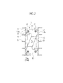
- a battery pack 1 includes a battery-stack group 6 having battery stacks 3, 5 arranged in two rows, a connection member 7 configured to connect the battery stacks 3, 5 of the battery-stack group 6 to each other, and a case 9 to house the battery stacks 3, 5 connected by the connection member 7. Note that a lid of the case 9 is not shown. Also, the number of battery stacks constituting the battery-stack group 6 is not limited to two, and may be three or more.
- the battery stacks 3, 5 are each formed by arranging multiple individual batteries 11 each formed in a plate shape, in a thickness direction of the batteries 11 (a row direction). Then, the multiple battery stacks 3, 5 are arranged, with a predetermined distance therebetween, in an orthogonal direction (a direction along the surfaces of the batteries 11) which is orthogonal to the row direction.
- the first battery stack 3 (a certain battery stack 3) arranged on the right side in Fig. 1 and the second battery stack 5 (an adjacent battery stack 5) arranged adjacently on the left side of the first battery stack 3 are provided.
- connection member 7 is formed integrally by connecting multiple connection parts having a Z shape in a plan view, in the longitudinal direction.
- connection member 7 is formed by integrally and repeatedly connecting a first connection part 13 extending from the first battery stack 3 side to the second battery stack 5 side in the orthogonal direction, and a second connection part 15 extending from an end portion of the first connection part 13 on the first battery stack 3 side toward the second battery stack 5 in a direction oblique to the orthogonal direction. Accordingly, an end portion 15a of the second connection part 15 on the second battery stack 5 side coincides with an end portion 13a of the first connection part 13 on the second battery stack 5 side.
- a connection part of a Z shape in a plan view is formed by a certain first connection part 13, a second connection part 15 connected to the first connection part 13, and another first connection part 13 connected to the second connection part 15.
- the second connection part 15 is provided between every adjacent ones of the multiple first connection parts 13, and all the second connection parts 15 extend in the same direction which is oblique to the orthogonal direction in a plan view.
- an extending direction B of each second connection part 15 intersects the orthogonal direction at an angle ⁇ .
- This angle ⁇ is set to smaller than 90°.
- support holes 17, 17 are formed in the left and right end portions 13a, 13b of each first connection part 13 of the connection member 7, respectively. Support pins 21 of support brackets 19 are inserted into these support holes 17, 17, and the connection member 7 is fixed to each support bracket 19 using a fastening member which is not shown.
- a protrusion portion 23 protruding upward is provided at a longitudinal middle portion of each second connection part 15 of the connection member 7. By this protrusion portion 23, the longitudinal cross section of the second connection part 15 is formed into a hat shape.
- An elliptical through-hole 25 extending long in the longitudinal direction of the connection member 7 (the row direction of the battery stacks 3, 5) is formed in the protrusion portion 23.
- each support bracket 19 is held between the individual batteries 11, 11, and the battery stacks 3, 5 are supported by the support brackets 19.
- a tip end of each battery 11 is provided with a terminal 12.
- each support bracket 19 is formed integrally of a body portion 27 held between the batteries 11, 11, a link portion 29 extending from an upper end of the body portion 27 in the orthogonal direction, and a support portion 31 being bent at and extending from a lower end of the link portion 29 in the row direction.
- the support portion 31 is provided with the support pin 21 protruding upward. As already described, this support pin 21 is inserted into and fastened to the corresponding support hole 17 of the connection member 7.
- an arcuate cutout 35 dented upward is formed in a lower portion of a base portion 11 of the link portion 29 of the support bracket 19.
- This cutout 35 makes the base portion 33 fragile, allowing the link portion 29 to elastically deform in a vertical direction with respect to the body portion 27, as shown with two-dot chain lines.
- the support portion 31 is bent at the lower end of the link portion 29 and extends therefrom in the row direction, and this lower end is formed into a bent portion 37 as shown with two-dot chain lines.
- the support portion 31 can elastically deform at the bent portion 37 in the vertical direction with respect to the link portion 29.
- connection member 7 reaction forces generated in the connection member 7 when loads are applied to the battery pack 1 are described using Fig. 8 .
- the reaction forces F1 can prevent the left and right battery stacks 3, 5 from approaching each other in the orthogonal direction. Further, the reaction forces F2 can prevent the individual batteries 11, 11 from approaching each other in the row direction. Furthermore, the reaction forces F3 can not only prevent the left and right battery stacks 3, 5 from approaching each other in the orthogonal direction, but also prevent the individual batteries 11, 11 from approaching each other in the row direction.
- the battery pack 1 is constructed by arranging multiple individual batteries 11 in the row direction to form each of the battery stacks 3, 5, arranging the battery stacks 3, 5 in multiple rows in the orthogonal direction which is orthogonal to the row direction, and then connecting, via the connection member 7, the first battery stack 3 which is a certain battery stack to the second battery stack 5 which is a battery stack adjacent to the certain battery stack.
- connection member 7 includes the first connection parts 13 and the second connection parts 15.
- Each first connection part 13 extends from the first battery stack 3 to the second battery stack 5 in the orthogonal direction.
- one end portion 13b of each first connection part 13 supports the first battery stack 3 and the other end portion 13a thereof supports the second battery stack 5.
- Each second connection part 15 extends from the end portion 13b of the first connection part 13 on the first battery stack 3 side toward the second battery stack 5 in a direction oblique to the orthogonal direction in a plan view.
- the reaction forces F1 are generated toward the outside in the orthogonal direction in the first connection parts 13 of the connection member 7.
- the reaction forces F2 are generated toward the outside in the longitudinal direction in the second connection parts 15 of the connection member 7.
- the loads f1 and f2 are applied simultaneously, the combined forces F3 of the reaction forces F1 and F2 are generated.
- the reaction forces F1 can prevent the left and right battery stacks 3, 5 from approaching each other in the orthogonal direction and thereby prevent interference between the battery stacks 3, 5. Meanwhile, the reaction forces F2 can prevent the individual batteries 11, 11 from approaching each other in the row direction and thereby prevent interference between the batteries 11, 11. Furthermore, the reaction forces F3 can prevent not only interference between the left and right battery stacks 3, 5, but also interference between the individual batteries 11, 11.
- the second connection part 15 is provided between every adjacent first connection parts 13, 13 of the multiple first connection parts 13, and all the second connection parts 15 extend in the same direction which is oblique to the orthogonal direction in a plan view.
- the reaction forces F2 are generated in the extending direction B of the second connection parts 15 (see Figs. 3 ) as shown in Fig. 8 . Since the second connection part 15 is provided between every adjacent first connection parts 13, 13, all the reaction forces F2 on the right side of the connection member 7 in Fig. 8 are directed to an upper right direction in Fig. 8 . Moreover, all the reaction forces F2 on the left side of the connection member 7 in Fig. 8 are directed to a lower left direction in Fig. 8 .
- the loads F2 act on all of the individual batteries 11 constituting the first battery stack 3 to move them in the same direction, and the loads F2 also act on all of the individual batteries 11 constituting the second battery stack 5 to move them in the same direction. Accordingly, the individual batteries can be efficiently prevented from approaching each other in the row direction and interfering with each other.
- Each support bracket 19 is formed integrally of the body portion 27 held between the individual batteries 11, 11, the support portion 31 supported by the connection member 7, and the link portion 29 linking the body portion 27 and the support portion 31 to each other. At least the link portion 29 is configured to be elastically deformable.
- the support portion 31 is bent at and extends from the end portion of the link portion 29, and is configured to be elastically deformable at this bent portion 37 with respect to the link portion 29.
- the through-hole 25 is formed in the longitudinal middle portion of each second connection part 15 of the connection member 7.
- the second connection part 15 a portion near the through-hole 25 is fragile. Accordingly, when a compression load is applied to the second connection part 15 in its longitudinal direction, the second connection part 15 elastically deforms by a large amount at the portion near the through-hole 25, allowing efficient mitigation of impacts of the loads f1, f2.
- each second connection part 15 of the connection member 7 protrudes in the thickness direction of the connection member 7 in such a manner that the longitudinal cross section of the second connection part 15 is formed into a hat shape.
- the second connection part 15 when a compression load is applied to the second connection part 15 in its longitudinal direction, the second connection part 15 easily deforms by being bent upward which is the direction of the protrusion. Thus, impacts of the loads f1, f2 can be efficiently mitigated.
- adjacent battery stacks can keep a distance from each other, and interference between individual batteries in each battery stack can be prevented.
Landscapes
- Chemical & Material Sciences (AREA)
- Chemical Kinetics & Catalysis (AREA)
- Electrochemistry (AREA)
- General Chemical & Material Sciences (AREA)
- Battery Mounting, Suspending (AREA)
Abstract
Description
- The present invention relates to a battery pack installed in an electric automobile or the like.
- A battery pack conventionally known includes battery stacks each formed by arranging multiple individual batteries in a row direction (in a thickness direction of the batteries) (see, for example, Patent Document 1). In this battery pack, multiple rows of such battery stacks are arranged side by side with a predetermined distance therebetween in an orthogonal direction which is orthogonal to the row direction, and the battery stacks adjacent in the orthogonal direction are connected to each other with connection brackets of an X shape in a plan view. These connection brackets allow the battery stacks adjacent in the orthogonal direction to keep a constant distance therebetween.
- Patent Document 1: Japanese Patent Application Publication No.
Hei 9(1997)-219181 - However, in the battery pack described in Patent Document 1, the adjacent battery stacks are connected to each other with the connection brackets of an X shape in a plan view. For this reason, when a load is applied to the battery pack in the orthogonal direction to make the adjacent battery stacks approach each other, individual batteries connected by the connection bracket move in the row direction to interfere with each other, and this might cause damage to the batteries.
- In view of the above, the present invention has an objective of, while making adjacent battery stacks keep a constant distance from each other, preventing individual batteries in the battery stack from interfering with each other even when a load is applied in a direction orthogonal to a row direction.
- The present invention provides a battery pack configured as follows. First, multiple individual batteries are arranged in a row direction to form a battery stack. Then, multiple rows of such battery stacks are arranged in an orthogonal direction which is orthogonal to the row direction to form a battery-stack group. Then, among these battery stacks, a certain battery stack and another battery stack adjacent to the certain battery stack are connected to each other via a connection member.
- The connection member includes multiple first connection parts and a second connection part. The first connection parts each extend from the certain battery stack to the other adjacent battery stack in the orthogonal direction. Here, one end portion of each first connection part supports the certain battery stack and another end portion thereof supports the adjacent battery stack.
- The second connection part is located between at least one pair of adjacent first connection parts of the multiple first connection parts, and connects an end portion of one of the first connection parts on the certain battery stack side to an end portion of the other one of the first connection parts on the other adjacent battery stack side.
- Accordingly, with the adjacent battery stacks keeping a distance from each other, interference between the individual batteries of each battery stack can be prevented even when loads are applied in a direction orthogonal to the row direction.
- More specifically, when loads are applied to the battery pack toward the inside thereof in the orthogonal direction, a reaction force toward the outside in the orthogonal direction is generated in each first connection part of the connection member. Thus, the adjacent battery stacks are prevented from approaching each other in the orthogonal direction, which can consequently prevent interference between the battery stacks.
- Further, when loads are applied to the battery pack toward the inside thereof in the row direction, a reaction force toward the outside in a longitudinal direction of the second connection part is generated in the second connection part of the connection member. Thus, the individual batteries are prevented from approaching each other in the row direction, which can consequently prevent interference between the batteries.
- Furthermore, when the loads in the row direction and the loads in the orthogonal direction are applied simultaneously, not only the interference between the adjacent battery stacks, but also the interference between the individual batteries can be prevented.
-
- [
Fig. 1] Fig. 1 is a plan view of a battery pack according to an embodiment of the present invention, seen from above. - [
Fig. 2] Fig. 2 is a plan view of a main part ofFig. 1 shown in an enlarged manner. - [
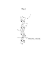
Fig. 3] Fig. 3 is a plan view showing a connection member inFig. 1 . - [
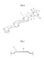
Fig. 4] Fig. 4 is a perspective view showing the connection member inFig. 1 in an enlarged manner. - [
Fig. 5] Fig. 5 is a sectional view taken along line A-A inFig. 3 . - [
Fig. 6] Fig. 6 is a perspective view showing how a support bracket is connected to the connection member. - [
Fig. 7] Fig. 7 is a perspective view showing an upper end portion of the support bracket in an enlarged manner. - [
Fig. 8] Fig. 8 is a schematic diagram showing reaction forces of the connection member generated when loads are applied to the battery pack. - An embodiment of the present invention is described in detail with the drawings.
- As shown in
Fig. 1 , a battery pack 1 according to this embodiment includes a battery-stack group 6 havingbattery stacks connection member 7 configured to connect thebattery stacks stack group 6 to each other, and acase 9 to house thebattery stacks connection member 7. Note that a lid of thecase 9 is not shown. Also, the number of battery stacks constituting the battery-stack group 6 is not limited to two, and may be three or more. - The battery stacks 3, 5 are each formed by arranging multiple
individual batteries 11 each formed in a plate shape, in a thickness direction of the batteries 11 (a row direction). Then, themultiple battery stacks Fig. 1 and the second battery stack 5 (an adjacent battery stack 5) arranged adjacently on the left side of thefirst battery stack 3 are provided. - As shown in
Figs. 2 to 4 , theconnection member 7 is formed integrally by connecting multiple connection parts having a Z shape in a plan view, in the longitudinal direction. - More specifically, as shown in
Figs. 2 and3 , theconnection member 7 is formed by integrally and repeatedly connecting afirst connection part 13 extending from thefirst battery stack 3 side to thesecond battery stack 5 side in the orthogonal direction, and asecond connection part 15 extending from an end portion of thefirst connection part 13 on thefirst battery stack 3 side toward thesecond battery stack 5 in a direction oblique to the orthogonal direction. Accordingly, anend portion 15a of thesecond connection part 15 on thesecond battery stack 5 side coincides with anend portion 13a of thefirst connection part 13 on thesecond battery stack 5 side. A connection part of a Z shape in a plan view is formed by a certainfirst connection part 13, asecond connection part 15 connected to thefirst connection part 13, and anotherfirst connection part 13 connected to thesecond connection part 15. - Particularly, as shown in
Fig. 3 , in theconnection member 7 according to this embodiment, thesecond connection part 15 is provided between every adjacent ones of the multiplefirst connection parts 13, and all thesecond connection parts 15 extend in the same direction which is oblique to the orthogonal direction in a plan view. - In other words, an extending direction B of each
second connection part 15 intersects the orthogonal direction at an angle θ. This angle θ is set to smaller than 90°. - Further, as shown in
Fig. 4 , supportholes right end portions first connection part 13 of theconnection member 7, respectively.Support pins 21 ofsupport brackets 19 are inserted into thesesupport holes connection member 7 is fixed to eachsupport bracket 19 using a fastening member which is not shown. As shown inFigs. 4 and 5 , aprotrusion portion 23 protruding upward is provided at a longitudinal middle portion of eachsecond connection part 15 of theconnection member 7. By thisprotrusion portion 23, the longitudinal cross section of thesecond connection part 15 is formed into a hat shape. An elliptical through-hole 25 extending long in the longitudinal direction of the connection member 7 (the row direction of thebattery stacks 3, 5) is formed in theprotrusion portion 23. - Further, as shown in
Fig. 2 , eachsupport bracket 19 is held between theindividual batteries battery stacks support brackets 19. A tip end of eachbattery 11 is provided with a terminal 12. - As shown in
Figs. 6 and 7 , eachsupport bracket 19 is formed integrally of abody portion 27 held between thebatteries link portion 29 extending from an upper end of thebody portion 27 in the orthogonal direction, and asupport portion 31 being bent at and extending from a lower end of thelink portion 29 in the row direction. Thesupport portion 31 is provided with thesupport pin 21 protruding upward. As already described, thissupport pin 21 is inserted into and fastened to thecorresponding support hole 17 of theconnection member 7. - As shown in
Fig. 7 , anarcuate cutout 35 dented upward is formed in a lower portion of abase portion 11 of thelink portion 29 of thesupport bracket 19. Thiscutout 35 makes thebase portion 33 fragile, allowing thelink portion 29 to elastically deform in a vertical direction with respect to thebody portion 27, as shown with two-dot chain lines. Further, thesupport portion 31 is bent at the lower end of thelink portion 29 and extends therefrom in the row direction, and this lower end is formed into abent portion 37 as shown with two-dot chain lines. Thesupport portion 31 can elastically deform at thebent portion 37 in the vertical direction with respect to thelink portion 29. - Next, reaction forces generated in the
connection member 7 when loads are applied to the battery pack 1 are described usingFig. 8 . - First, when loads f1 are applied to the battery pack 1 toward the inside thereof in the orthogonal direction, as shown with arrows in
Fig. 1 , the left andright battery stacks - Then, the
support brackets 19 and the support pins 21 supporting thebattery stacks Fig. 2 ). Thereby, as shown inFig. 8 , thefirst connection parts 13 of theconnection member 7 are compressed from their both end portions in the orthogonal direction, and reaction forces F1 (see arrows inFig. 8 ) are generated toward the outside in the orthogonal direction in such a manner as to react against the compression forces. - On the other hand, when loads f2 are applied to the battery pack 1 toward the inside thereof in the row direction as shown with arrows in
Fig. 1 , theindividual batteries 11 constituting the left andright battery stacks - Then, the
support brackets 19 and the support pins 21 supporting thebattery stacks Fig. 2 ). Thereby, as shown inFig. 8 , thesecond connection parts 15 of theconnection member 7 are compressed from their both longitudinal end portions, and reaction forces F2 (see arrows inFig. 8 ) are generated toward the outside in the longitudinal direction in such a manner as to react against the compression forces. - Note that if the loads f1 and the loads f2 are applied to the battery pack 1 simultaneously, the reaction forces are combined forces F3 of F1 and F2 in
Fig. 8 . - The reaction forces F1 can prevent the left and
right battery stacks individual batteries right battery stacks individual batteries - Operation and advantageous effects of this embodiment are described below.
- (1) The battery pack 1 according to this embodiment is constructed by arranging multiple
individual batteries 11 in the row direction to form each of thebattery stacks battery stacks connection member 7, thefirst battery stack 3 which is a certain battery stack to thesecond battery stack 5 which is a battery stack adjacent to the certain battery stack. - The
connection member 7 includes thefirst connection parts 13 and thesecond connection parts 15. - Each
first connection part 13 extends from thefirst battery stack 3 to thesecond battery stack 5 in the orthogonal direction. Here, oneend portion 13b of eachfirst connection part 13 supports thefirst battery stack 3 and theother end portion 13a thereof supports thesecond battery stack 5. - Each
second connection part 15 extends from theend portion 13b of thefirst connection part 13 on thefirst battery stack 3 side toward thesecond battery stack 5 in a direction oblique to the orthogonal direction in a plan view. - Accordingly, when the loads f1 are applied to the battery pack 1 toward the inside thereof in the orthogonal direction, the reaction forces F1 are generated toward the outside in the orthogonal direction in the
first connection parts 13 of theconnection member 7. Further, when the loads f2 are applied to the battery pack 1 toward the inside thereof in the row direction, the reaction forces F2 are generated toward the outside in the longitudinal direction in thesecond connection parts 15 of theconnection member 7. Furthermore, when the loads f1 and f2 are applied simultaneously, the combined forces F3 of the reaction forces F1 and F2 are generated. - The reaction forces F1 can prevent the left and
right battery stacks battery stacks individual batteries batteries right battery stacks individual batteries - (2) The
second connection part 15 is provided between every adjacentfirst connection parts first connection parts 13, and all thesecond connection parts 15 extend in the same direction which is oblique to the orthogonal direction in a plan view. - Accordingly, when the loads f2 are applied to the battery pack 1 toward the inside thereof in the row direction, the reaction forces F2 are generated in the extending direction B of the second connection parts 15 (see
Figs. 3 ) as shown inFig. 8 . Since thesecond connection part 15 is provided between every adjacentfirst connection parts connection member 7 inFig. 8 are directed to an upper right direction inFig. 8 . Moreover, all the reaction forces F2 on the left side of theconnection member 7 inFig. 8 are directed to a lower left direction inFig. 8 . Thus, the loads F2 act on all of theindividual batteries 11 constituting thefirst battery stack 3 to move them in the same direction, and the loads F2 also act on all of theindividual batteries 11 constituting thesecond battery stack 5 to move them in the same direction. Accordingly, the individual batteries can be efficiently prevented from approaching each other in the row direction and interfering with each other. - (3) The
support brackets 19 are attached to each of thefirst battery stack 3 and thesecond battery stack 5, and thesesupport brackets connection member 7. - These
support brackets 19 enable theconnection member 7 to couple thebattery stacks - (4) Each
support bracket 19 is formed integrally of thebody portion 27 held between theindividual batteries support portion 31 supported by theconnection member 7, and thelink portion 29 linking thebody portion 27 and thesupport portion 31 to each other. At least thelink portion 29 is configured to be elastically deformable. - Accordingly, when the loads f1, f2 are applied to the battery pack 1, impacts of the loads f1, f2 can be mitigated by the elastic deformation of the
link portion 29. - (5) The
support portion 31 is bent at and extends from the end portion of thelink portion 29, and is configured to be elastically deformable at thisbent portion 37 with respect to thelink portion 29. - Accordingly, when the loads f1, f2 are applied to the battery pack 1, impacts of the loads f1, f2 can be mitigated by the elastic deformation of the
support portion 31. - (6) The through-
hole 25 is formed in the longitudinal middle portion of eachsecond connection part 15 of theconnection member 7. - For this reason, in the
second connection part 15, a portion near the through-hole 25 is fragile. Accordingly, when a compression load is applied to thesecond connection part 15 in its longitudinal direction, thesecond connection part 15 elastically deforms by a large amount at the portion near the through-hole 25, allowing efficient mitigation of impacts of the loads f1, f2. - (7) The longitudinal middle portion of each
second connection part 15 of theconnection member 7 protrudes in the thickness direction of theconnection member 7 in such a manner that the longitudinal cross section of thesecond connection part 15 is formed into a hat shape. - Accordingly, when a compression load is applied to the
second connection part 15 in its longitudinal direction, thesecond connection part 15 easily deforms by being bent upward which is the direction of the protrusion. Thus, impacts of the loads f1, f2 can be efficiently mitigated. - The entire contents of Japanese Patent Application No.
2010-232324 (filed on October 15, 2010 - Although the present invention has been described through the embodiment, it is obvious to those skilled in the art that the present invention is not limited to the foregoing description and can be modified and improved variously.
- According to the battery pack according to the present invention in which battery stacks each having stacked batteries are arranged in rows, adjacent battery stacks can keep a distance from each other, and interference between individual batteries in each battery stack can be prevented.
-
- 1
- battery pack
- 3
- first battery stack (certain battery stack)
- 5
- second battery stack (adjacent battery stack)
- 6
- battery-stack group
- 7
- connection member
- 11
- battery
- 13
- first connection part
- 15
- second connection part
- 19
- support bracket
- 23
- protrusion portion
- 25
- through-hole
- 27
- body portion
- 29
- link portion
- 37
- bent portion
Claims (7)
- a battery-stack group formed by arranging a plurality of battery stacks in a plurality of rows in an orthogonal direction orthogonal to a row direction, each battery stack being formed by arranging a plurality of individual batteries in the row direction;
anda connection member configured to connect a certain battery stack of the battery-stack group to another battery stack of the battery-stack group adjacent to the certain battery stack, whereinthe connection member includes
a plurality of first connection parts extending from the certain battery stack to the adjacent battery stack in the orthogonal direction, in which one end portion of each first connection part supports the certain battery stack and another end portion of each first connection part supports the adjacent battery stack, and
a second connection part located between at least one pair of first connection parts adjacent to each other among the plurality of first connection parts, the second connection part connecting an end portion of one of the pair of first connection parts on the certain battery stack side to an end portion of another one of the pair of first connection parts on the adjacent battery stack side. - The battery pack according to claim 1, wherein
the second connection part is provided between every adjacent ones of the plurality of first connection parts, and
all the second connection parts extend in the same direction which is oblique to the orthogonal direction in a plan view. - The battery pack according to any one of claims 1 and 2, wherein
support brackets are attached to the certain battery stack and the adjacent battery stack, respectively, and
the support brackets are connected to each other via the connection member. - The battery pack according to claim 3, wherein
the support brackets are each formed integrally of a body portion held between the individual batteries, a support portion supported by the connection member, and a link portion linking the body portion and the support portion to each other, and
at least the link portion is configured to be elastically deformable. - The battery pack according to claim 4, wherein
the support portion is bent at and extends from an end portion of the link portion, and
the support portion is configured to be elastically deformable at the bent portion provided at the end portion, with respect to the link portion. - The battery pack according to any one of claims 1 to 5, wherein
a through-hole is formed in a longitudinal middle portion of the second connection part of the connection member. - The battery pack according to any one of claims 1 to 6, wherein
a longitudinal middle portion of the second connection part of the connection member protrudes in a thickness direction of the connection member in such a manner that a longitudinal cross section of the second connection part is formed into a hat shape.
Applications Claiming Priority (2)
| Application Number | Priority Date | Filing Date | Title |
|---|---|---|---|
| JP2010232324 | 2010-10-15 | ||
| PCT/JP2011/073055 WO2012050038A1 (en) | 2010-10-15 | 2011-10-06 | Battery pack |
Publications (3)
| Publication Number | Publication Date |
|---|---|
| EP2629349A1 true EP2629349A1 (en) | 2013-08-21 |
| EP2629349A4 EP2629349A4 (en) | 2015-09-02 |
| EP2629349B1 EP2629349B1 (en) | 2016-09-21 |
Family
ID=45938267
Family Applications (1)
| Application Number | Title | Priority Date | Filing Date |
|---|---|---|---|
| EP11832473.0A Not-in-force EP2629349B1 (en) | 2010-10-15 | 2011-10-06 | Battery pack |
Country Status (6)
| Country | Link |
|---|---|
| US (1) | US9356265B2 (en) |
| EP (1) | EP2629349B1 (en) |
| JP (1) | JP5500262B2 (en) |
| KR (1) | KR101386860B1 (en) |
| CN (1) | CN103081168B (en) |
| WO (1) | WO2012050038A1 (en) |
Families Citing this family (1)
| Publication number | Priority date | Publication date | Assignee | Title |
|---|---|---|---|---|
| JP6070265B2 (en) * | 2013-02-27 | 2017-02-01 | 日産自動車株式会社 | Battery pack mounting structure |
Family Cites Families (11)
| Publication number | Priority date | Publication date | Assignee | Title |
|---|---|---|---|---|
| JPH03155042A (en) * | 1989-11-10 | 1991-07-03 | Japan Storage Battery Co Ltd | Installation method of sealed-type secondary batteries |
| JP3513878B2 (en) * | 1993-05-28 | 2004-03-31 | ソニー株式会社 | Cell and battery assembly |
| JP3233320B2 (en) * | 1994-01-14 | 2001-11-26 | 本田技研工業株式会社 | Battery box battery fixing device |
| JP3998736B2 (en) | 1996-02-13 | 2007-10-31 | 日産自動車株式会社 | Flat battery module |
| JP5332135B2 (en) * | 2007-05-16 | 2013-11-06 | ソニー株式会社 | Battery pack |
| CN101809785B (en) * | 2007-08-02 | 2013-12-04 | 江森自控帅福得先进能源动力系统有限责任公司 | Storage battery assembly |
| CA2721548C (en) * | 2008-04-14 | 2017-10-17 | A123 Systems, Inc. | Flexible voltage nested battery module design |
| JP2010009809A (en) * | 2008-06-25 | 2010-01-14 | Toyota Motor Corp | Power supply device, and vehicle |
| CN102197509B (en) * | 2008-09-09 | 2014-11-26 | 江森自控帅福得先进能源动力系统有限责任公司 | Interconnect Gasket Assemblies for Battery Assemblies |
| JP5506221B2 (en) | 2009-03-26 | 2014-05-28 | スタンレー電気株式会社 | Method for manufacturing ZnO-based semiconductor element |
| KR101050318B1 (en) * | 2009-04-16 | 2011-07-19 | 에스비리모티브 주식회사 | Secondary battery module |
-
2011
- 2011-10-06 CN CN201180042957.7A patent/CN103081168B/en not_active Expired - Fee Related
- 2011-10-06 JP JP2012538655A patent/JP5500262B2/en not_active Expired - Fee Related
- 2011-10-06 US US13/822,512 patent/US9356265B2/en not_active Expired - Fee Related
- 2011-10-06 KR KR1020137005655A patent/KR101386860B1/en not_active Expired - Fee Related
- 2011-10-06 EP EP11832473.0A patent/EP2629349B1/en not_active Not-in-force
- 2011-10-06 WO PCT/JP2011/073055 patent/WO2012050038A1/en not_active Ceased
Also Published As
| Publication number | Publication date |
|---|---|
| JP5500262B2 (en) | 2014-05-21 |
| US9356265B2 (en) | 2016-05-31 |
| EP2629349B1 (en) | 2016-09-21 |
| CN103081168A (en) | 2013-05-01 |
| CN103081168B (en) | 2016-04-20 |
| EP2629349A4 (en) | 2015-09-02 |
| JPWO2012050038A1 (en) | 2014-02-24 |
| US20130171488A1 (en) | 2013-07-04 |
| WO2012050038A1 (en) | 2012-04-19 |
| KR101386860B1 (en) | 2014-04-17 |
| KR20130043219A (en) | 2013-04-29 |
Similar Documents
| Publication | Publication Date | Title |
|---|---|---|
| EP2706593B1 (en) | Battery wiring module | |
| KR101084222B1 (en) | Battery Module with Improved Base Plate Structure | |
| EP3352244B1 (en) | Battery module comprising end plates having improved structure, and end plate member therefor | |
| US10128474B2 (en) | Cell module and cell pack | |
| JP6016737B2 (en) | In-battery wiring module of battery pack | |
| US10283743B2 (en) | Battery module | |
| KR102922367B1 (en) | Battery mounting sturcure for vehicle | |
| JP6053643B2 (en) | In-battery wiring module of battery pack | |
| US20200044211A1 (en) | Drawer-type battery pack | |
| US9331316B2 (en) | Battery cell holder | |
| US20130020448A1 (en) | Wire holding structure | |
| KR102082497B1 (en) | Fuse assembly structure of secondary battery pack | |
| JP2016058158A (en) | Battery pack | |
| EP2490277B1 (en) | Battery Module | |
| EP2899773B1 (en) | Assembled battery | |
| EP2629349B1 (en) | Battery pack | |
| EP3832751A1 (en) | Cell module fixing structure | |
| US20170012276A1 (en) | Battery pack | |
| EP4723331A1 (en) | Storage battery module | |
| JP2018037182A (en) | Battery module | |
| US9660287B2 (en) | Apparatus for preventing deformation of fuel cell stack | |
| KR20150131472A (en) | Apparatus for resisting fuel cell stack deformation | |
| JP2022002186A (en) | Battery module |
Legal Events
| Date | Code | Title | Description |
|---|---|---|---|
| PUAI | Public reference made under article 153(3) epc to a published international application that has entered the european phase |
Free format text: ORIGINAL CODE: 0009012 |
|
| 17P | Request for examination filed |
Effective date: 20130307 |
|
| AK | Designated contracting states |
Kind code of ref document: A1 Designated state(s): AL AT BE BG CH CY CZ DE DK EE ES FI FR GB GR HR HU IE IS IT LI LT LU LV MC MK MT NL NO PL PT RO RS SE SI SK SM TR |
|
| DAX | Request for extension of the european patent (deleted) | ||
| RA4 | Supplementary search report drawn up and despatched (corrected) |
Effective date: 20150730 |
|
| RIC1 | Information provided on ipc code assigned before grant |
Ipc: H01M 2/20 20060101ALI20150724BHEP Ipc: H01M 2/10 20060101AFI20150724BHEP |
|
| GRAP | Despatch of communication of intention to grant a patent |
Free format text: ORIGINAL CODE: EPIDOSNIGR1 |
|
| INTG | Intention to grant announced |
Effective date: 20160506 |
|
| RIN1 | Information on inventor provided before grant (corrected) |
Inventor name: KANEKO, TAKASHI Inventor name: YOSHINAGA, TOMOFUMI |
|
| GRAS | Grant fee paid |
Free format text: ORIGINAL CODE: EPIDOSNIGR3 |
|
| GRAA | (expected) grant |
Free format text: ORIGINAL CODE: 0009210 |
|
| AK | Designated contracting states |
Kind code of ref document: B1 Designated state(s): AL AT BE BG CH CY CZ DE DK EE ES FI FR GB GR HR HU IE IS IT LI LT LU LV MC MK MT NL NO PL PT RO RS SE SI SK SM TR |
|
| REG | Reference to a national code |
Ref country code: GB Ref legal event code: FG4D |
|
| REG | Reference to a national code |
Ref country code: CH Ref legal event code: EP |
|
| REG | Reference to a national code |
Ref country code: AT Ref legal event code: REF Ref document number: 831674 Country of ref document: AT Kind code of ref document: T Effective date: 20161015 |
|
| REG | Reference to a national code |
Ref country code: IE Ref legal event code: FG4D |
|
| REG | Reference to a national code |
Ref country code: FR Ref legal event code: PLFP Year of fee payment: 6 |
|
| REG | Reference to a national code |
Ref country code: DE Ref legal event code: R096 Ref document number: 602011030645 Country of ref document: DE |
|
| REG | Reference to a national code |
Ref country code: LT Ref legal event code: MG4D Ref country code: NL Ref legal event code: MP Effective date: 20160921 |
|
| PG25 | Lapsed in a contracting state [announced via postgrant information from national office to epo] |
Ref country code: RS Free format text: LAPSE BECAUSE OF FAILURE TO SUBMIT A TRANSLATION OF THE DESCRIPTION OR TO PAY THE FEE WITHIN THE PRESCRIBED TIME-LIMIT Effective date: 20160921 Ref country code: NO Free format text: LAPSE BECAUSE OF FAILURE TO SUBMIT A TRANSLATION OF THE DESCRIPTION OR TO PAY THE FEE WITHIN THE PRESCRIBED TIME-LIMIT Effective date: 20161221 Ref country code: FI Free format text: LAPSE BECAUSE OF FAILURE TO SUBMIT A TRANSLATION OF THE DESCRIPTION OR TO PAY THE FEE WITHIN THE PRESCRIBED TIME-LIMIT Effective date: 20160921 Ref country code: LT Free format text: LAPSE BECAUSE OF FAILURE TO SUBMIT A TRANSLATION OF THE DESCRIPTION OR TO PAY THE FEE WITHIN THE PRESCRIBED TIME-LIMIT Effective date: 20160921 |
|
| REG | Reference to a national code |
Ref country code: AT Ref legal event code: MK05 Ref document number: 831674 Country of ref document: AT Kind code of ref document: T Effective date: 20160921 |
|
| PG25 | Lapsed in a contracting state [announced via postgrant information from national office to epo] |
Ref country code: BE Free format text: LAPSE BECAUSE OF NON-PAYMENT OF DUE FEES Effective date: 20161031 Ref country code: SE Free format text: LAPSE BECAUSE OF FAILURE TO SUBMIT A TRANSLATION OF THE DESCRIPTION OR TO PAY THE FEE WITHIN THE PRESCRIBED TIME-LIMIT Effective date: 20160921 Ref country code: LV Free format text: LAPSE BECAUSE OF FAILURE TO SUBMIT A TRANSLATION OF THE DESCRIPTION OR TO PAY THE FEE WITHIN THE PRESCRIBED TIME-LIMIT Effective date: 20160921 Ref country code: GR Free format text: LAPSE BECAUSE OF FAILURE TO SUBMIT A TRANSLATION OF THE DESCRIPTION OR TO PAY THE FEE WITHIN THE PRESCRIBED TIME-LIMIT Effective date: 20161222 Ref country code: NL Free format text: LAPSE BECAUSE OF FAILURE TO SUBMIT A TRANSLATION OF THE DESCRIPTION OR TO PAY THE FEE WITHIN THE PRESCRIBED TIME-LIMIT Effective date: 20160921 |
|
| PG25 | Lapsed in a contracting state [announced via postgrant information from national office to epo] |
Ref country code: RO Free format text: LAPSE BECAUSE OF FAILURE TO SUBMIT A TRANSLATION OF THE DESCRIPTION OR TO PAY THE FEE WITHIN THE PRESCRIBED TIME-LIMIT Effective date: 20160921 Ref country code: EE Free format text: LAPSE BECAUSE OF FAILURE TO SUBMIT A TRANSLATION OF THE DESCRIPTION OR TO PAY THE FEE WITHIN THE PRESCRIBED TIME-LIMIT Effective date: 20160921 |
|
| PG25 | Lapsed in a contracting state [announced via postgrant information from national office to epo] |
Ref country code: IS Free format text: LAPSE BECAUSE OF FAILURE TO SUBMIT A TRANSLATION OF THE DESCRIPTION OR TO PAY THE FEE WITHIN THE PRESCRIBED TIME-LIMIT Effective date: 20170121 Ref country code: CZ Free format text: LAPSE BECAUSE OF FAILURE TO SUBMIT A TRANSLATION OF THE DESCRIPTION OR TO PAY THE FEE WITHIN THE PRESCRIBED TIME-LIMIT Effective date: 20160921 Ref country code: PL Free format text: LAPSE BECAUSE OF FAILURE TO SUBMIT A TRANSLATION OF THE DESCRIPTION OR TO PAY THE FEE WITHIN THE PRESCRIBED TIME-LIMIT Effective date: 20160921 Ref country code: AT Free format text: LAPSE BECAUSE OF FAILURE TO SUBMIT A TRANSLATION OF THE DESCRIPTION OR TO PAY THE FEE WITHIN THE PRESCRIBED TIME-LIMIT Effective date: 20160921 Ref country code: BG Free format text: LAPSE BECAUSE OF FAILURE TO SUBMIT A TRANSLATION OF THE DESCRIPTION OR TO PAY THE FEE WITHIN THE PRESCRIBED TIME-LIMIT Effective date: 20161221 Ref country code: SK Free format text: LAPSE BECAUSE OF FAILURE TO SUBMIT A TRANSLATION OF THE DESCRIPTION OR TO PAY THE FEE WITHIN THE PRESCRIBED TIME-LIMIT Effective date: 20160921 Ref country code: BE Free format text: LAPSE BECAUSE OF FAILURE TO SUBMIT A TRANSLATION OF THE DESCRIPTION OR TO PAY THE FEE WITHIN THE PRESCRIBED TIME-LIMIT Effective date: 20160921 Ref country code: PT Free format text: LAPSE BECAUSE OF FAILURE TO SUBMIT A TRANSLATION OF THE DESCRIPTION OR TO PAY THE FEE WITHIN THE PRESCRIBED TIME-LIMIT Effective date: 20170123 Ref country code: SM Free format text: LAPSE BECAUSE OF FAILURE TO SUBMIT A TRANSLATION OF THE DESCRIPTION OR TO PAY THE FEE WITHIN THE PRESCRIBED TIME-LIMIT Effective date: 20160921 Ref country code: ES Free format text: LAPSE BECAUSE OF FAILURE TO SUBMIT A TRANSLATION OF THE DESCRIPTION OR TO PAY THE FEE WITHIN THE PRESCRIBED TIME-LIMIT Effective date: 20160921 |
|
| REG | Reference to a national code |
Ref country code: CH Ref legal event code: PL |
|
| REG | Reference to a national code |
Ref country code: DE Ref legal event code: R097 Ref document number: 602011030645 Country of ref document: DE |
|
| PG25 | Lapsed in a contracting state [announced via postgrant information from national office to epo] |
Ref country code: IT Free format text: LAPSE BECAUSE OF FAILURE TO SUBMIT A TRANSLATION OF THE DESCRIPTION OR TO PAY THE FEE WITHIN THE PRESCRIBED TIME-LIMIT Effective date: 20160921 |
|
| REG | Reference to a national code |
Ref country code: IE Ref legal event code: MM4A |
|
| PLBE | No opposition filed within time limit |
Free format text: ORIGINAL CODE: 0009261 |
|
| STAA | Information on the status of an ep patent application or granted ep patent |
Free format text: STATUS: NO OPPOSITION FILED WITHIN TIME LIMIT |
|
| PG25 | Lapsed in a contracting state [announced via postgrant information from national office to epo] |
Ref country code: CH Free format text: LAPSE BECAUSE OF NON-PAYMENT OF DUE FEES Effective date: 20161031 Ref country code: DK Free format text: LAPSE BECAUSE OF FAILURE TO SUBMIT A TRANSLATION OF THE DESCRIPTION OR TO PAY THE FEE WITHIN THE PRESCRIBED TIME-LIMIT Effective date: 20160921 Ref country code: LI Free format text: LAPSE BECAUSE OF NON-PAYMENT OF DUE FEES Effective date: 20161031 |
|
| 26N | No opposition filed |
Effective date: 20170622 |
|
| PG25 | Lapsed in a contracting state [announced via postgrant information from national office to epo] |
Ref country code: LU Free format text: LAPSE BECAUSE OF NON-PAYMENT OF DUE FEES Effective date: 20161006 |
|
| REG | Reference to a national code |
Ref country code: FR Ref legal event code: PLFP Year of fee payment: 7 |
|
| PG25 | Lapsed in a contracting state [announced via postgrant information from national office to epo] |
Ref country code: IE Free format text: LAPSE BECAUSE OF NON-PAYMENT OF DUE FEES Effective date: 20161006 Ref country code: SI Free format text: LAPSE BECAUSE OF FAILURE TO SUBMIT A TRANSLATION OF THE DESCRIPTION OR TO PAY THE FEE WITHIN THE PRESCRIBED TIME-LIMIT Effective date: 20160921 |
|
| PG25 | Lapsed in a contracting state [announced via postgrant information from national office to epo] |
Ref country code: HU Free format text: LAPSE BECAUSE OF FAILURE TO SUBMIT A TRANSLATION OF THE DESCRIPTION OR TO PAY THE FEE WITHIN THE PRESCRIBED TIME-LIMIT; INVALID AB INITIO Effective date: 20111006 Ref country code: CY Free format text: LAPSE BECAUSE OF FAILURE TO SUBMIT A TRANSLATION OF THE DESCRIPTION OR TO PAY THE FEE WITHIN THE PRESCRIBED TIME-LIMIT Effective date: 20160921 |
|
| PG25 | Lapsed in a contracting state [announced via postgrant information from national office to epo] |
Ref country code: HR Free format text: LAPSE BECAUSE OF FAILURE TO SUBMIT A TRANSLATION OF THE DESCRIPTION OR TO PAY THE FEE WITHIN THE PRESCRIBED TIME-LIMIT Effective date: 20160921 Ref country code: MC Free format text: LAPSE BECAUSE OF FAILURE TO SUBMIT A TRANSLATION OF THE DESCRIPTION OR TO PAY THE FEE WITHIN THE PRESCRIBED TIME-LIMIT Effective date: 20160921 Ref country code: MT Free format text: LAPSE BECAUSE OF NON-PAYMENT OF DUE FEES Effective date: 20161031 Ref country code: MK Free format text: LAPSE BECAUSE OF FAILURE TO SUBMIT A TRANSLATION OF THE DESCRIPTION OR TO PAY THE FEE WITHIN THE PRESCRIBED TIME-LIMIT Effective date: 20160921 |
|
| REG | Reference to a national code |
Ref country code: FR Ref legal event code: PLFP Year of fee payment: 8 |
|
| PG25 | Lapsed in a contracting state [announced via postgrant information from national office to epo] |
Ref country code: AL Free format text: LAPSE BECAUSE OF FAILURE TO SUBMIT A TRANSLATION OF THE DESCRIPTION OR TO PAY THE FEE WITHIN THE PRESCRIBED TIME-LIMIT Effective date: 20160921 Ref country code: TR Free format text: LAPSE BECAUSE OF FAILURE TO SUBMIT A TRANSLATION OF THE DESCRIPTION OR TO PAY THE FEE WITHIN THE PRESCRIBED TIME-LIMIT Effective date: 20160921 |
|
| REG | Reference to a national code |
Ref country code: DE Ref legal event code: R079 Ref document number: 602011030645 Country of ref document: DE Free format text: PREVIOUS MAIN CLASS: H01M0002100000 Ipc: H01M0050200000 |
|
| PGFP | Annual fee paid to national office [announced via postgrant information from national office to epo] |
Ref country code: FR Payment date: 20210913 Year of fee payment: 11 |
|
| PGFP | Annual fee paid to national office [announced via postgrant information from national office to epo] |
Ref country code: GB Payment date: 20210825 Year of fee payment: 11 |
|
| PGFP | Annual fee paid to national office [announced via postgrant information from national office to epo] |
Ref country code: DE Payment date: 20210824 Year of fee payment: 11 |
|
| REG | Reference to a national code |
Ref country code: DE Ref legal event code: R119 Ref document number: 602011030645 Country of ref document: DE |
|
| GBPC | Gb: european patent ceased through non-payment of renewal fee |
Effective date: 20221006 |
|
| PG25 | Lapsed in a contracting state [announced via postgrant information from national office to epo] |
Ref country code: FR Free format text: LAPSE BECAUSE OF NON-PAYMENT OF DUE FEES Effective date: 20221031 Ref country code: DE Free format text: LAPSE BECAUSE OF NON-PAYMENT OF DUE FEES Effective date: 20230503 |
|
| PG25 | Lapsed in a contracting state [announced via postgrant information from national office to epo] |
Ref country code: GB Free format text: LAPSE BECAUSE OF NON-PAYMENT OF DUE FEES Effective date: 20221006 |