EP2629302A1 - Nuclear power facility control system - Google Patents
Nuclear power facility control system Download PDFInfo
- Publication number
- EP2629302A1 EP2629302A1 EP11832374.0A EP11832374A EP2629302A1 EP 2629302 A1 EP2629302 A1 EP 2629302A1 EP 11832374 A EP11832374 A EP 11832374A EP 2629302 A1 EP2629302 A1 EP 2629302A1
- Authority
- EP
- European Patent Office
- Prior art keywords
- emergency
- control device
- signal
- selector switch
- switch
- Prior art date
- Legal status (The legal status is an assumption and is not a legal conclusion. Google has not performed a legal analysis and makes no representation as to the accuracy of the status listed.)
- Withdrawn
Links
Images


Classifications
-
- G—PHYSICS
- G21—NUCLEAR PHYSICS; NUCLEAR ENGINEERING
- G21D—NUCLEAR POWER PLANT
- G21D3/00—Control of nuclear power plant
- G21D3/04—Safety arrangements
-
- G—PHYSICS
- G21—NUCLEAR PHYSICS; NUCLEAR ENGINEERING
- G21D—NUCLEAR POWER PLANT
- G21D3/00—Control of nuclear power plant
- G21D3/001—Computer implemented control
-
- Y—GENERAL TAGGING OF NEW TECHNOLOGICAL DEVELOPMENTS; GENERAL TAGGING OF CROSS-SECTIONAL TECHNOLOGIES SPANNING OVER SEVERAL SECTIONS OF THE IPC; TECHNICAL SUBJECTS COVERED BY FORMER USPC CROSS-REFERENCE ART COLLECTIONS [XRACs] AND DIGESTS
- Y02—TECHNOLOGIES OR APPLICATIONS FOR MITIGATION OR ADAPTATION AGAINST CLIMATE CHANGE
- Y02E—REDUCTION OF GREENHOUSE GAS [GHG] EMISSIONS, RELATED TO ENERGY GENERATION, TRANSMISSION OR DISTRIBUTION
- Y02E30/00—Energy generation of nuclear origin
-
- Y—GENERAL TAGGING OF NEW TECHNOLOGICAL DEVELOPMENTS; GENERAL TAGGING OF CROSS-SECTIONAL TECHNOLOGIES SPANNING OVER SEVERAL SECTIONS OF THE IPC; TECHNICAL SUBJECTS COVERED BY FORMER USPC CROSS-REFERENCE ART COLLECTIONS [XRACs] AND DIGESTS
- Y02—TECHNOLOGIES OR APPLICATIONS FOR MITIGATION OR ADAPTATION AGAINST CLIMATE CHANGE
- Y02E—REDUCTION OF GREENHOUSE GAS [GHG] EMISSIONS, RELATED TO ENERGY GENERATION, TRANSMISSION OR DISTRIBUTION
- Y02E30/00—Energy generation of nuclear origin
- Y02E30/30—Nuclear fission reactors
Definitions
- the present invention relates to a control system for a nuclear facility that allows controlling an operation of the nuclear facility within an evacuation area for evacuation when an emergency occurs.
- a known remote shutdown system includes a central control room control panel, a remote shutdown panel, an on-site multiple transmission device panel, and a mode selection switch (for example, see Patent Literature 1).
- the central control room control panel is disposed within a central control room and remotely controls a nuclear reactor.
- the remote shutdown panel is disposed outside of the central control room and remotely shuts down the nuclear reactor.
- the on-site multiple transmission device panel controls a plurality of loads at the nuclear reactor.
- the mode selection switch provides either one of two couplings of a coupling between the central control room control panel and the on-site multiple transmission device panel or a coupling between the remote shutdown panel and the on-site multiple transmission device panel.
- Patent Literature 1 Japanese Patent Application Laid-open No. 59-174787
- the conventional remote shutdown system has a mode selection switch that is an analog circuit switch with a contact point. Therefore, to collectively perform switching operations, coaxial cables are necessary to be disposed as multiplex transmission lines between the central control room control panel and the on-site multiple transmission device panel and between the remote shutdown panel and the on-site multiple transmission device panel. Accordingly, in the case where switching operations are collectively performed, a control circuit or a control device for multiple transmission is necessary to be separately added around the mode selection switch. That is, although the conventional remote shutdown system can collectively perform switching operations with analog equipment, the analog equipment differs from the central control room control panel in operation. Accordingly, this imposes burden on an operator. An incorrect operation of the mode selection switch or short circuit of the mode selection switch due to failure, fire spread, or similar trouble, may cause an incorrect switching operation where a coupling is unintentionally switched.
- the control system for a nuclear facility that allows controlling an operation of a nuclear facility in an evacuation area for evacuation when an emergency occurs, the control system includes: a first operation control device for ordinary use, the first operation control device being disposed in a non-evacuation area, the non-evacuation area being an area other than the evacuation area; a second operation control device for emergency, the second operation control device being disposed in the evacuation area; a control device connectable to the first operation control device or the second operation control device; a signal switching unit configured to switch from a normal coupling between the control device and the first operation control device to an emergency coupling between the control device and the second operation control device based on an emergency switch signal to be input; a first selector switch disposed in the non-evacuation area, the first selector switch being configured to output an emergency switch signal by a switching operation to the emergency coupling; a second selector switch disposed in the evacuation area, the second selector switch being configured to output an emergency switch signal
- operating the first selector switch and the second selector switch to switch from the normal coupling to the emergency coupling facilitates collective switching from an operation with the first operation control device to an operation with the second operation control device.
- switching the first selector switch to the emergency coupling side and switching the second selector switch to the emergency coupling side allow inputting the emergency switch signals to an AND circuit from the first selector switch and the second selector switch.
- This allows the AND circuit to output the emergency switch signal to the signal switching unit.
- the signal switching unit receives the emergency switch signal and is allowed to switch from the normal coupling to the emergency coupling. Therefore, even if one of the first selector switch and the second selector switch incorrectly outputs the emergency switch signal, the AND circuit does not output the emergency switch signal. This consequently ensures reduced occurrence of incorrect switching between the operation control devices.
- control device includes a processing device coupled to the signal switching unit, and the processing device is configured to: process a signal input to/output from the first operation control device through the signal switching unit; and process a signal input to/output from the second operation control device through the signal switching unit.
- This configuration allows the first operation control device and the second operation control device to share the processing device. This eliminates the need for an additional processing device, thus reducing cost escalation of the device.
- At least any one of the first selector switch and the second selector switch includes: a first operating unit configured to output the emergency switch signal by a switching operation to the emergency coupling; a second operating unit configured to output the emergency switch signal by a switching operation to the emergency coupling; and an OR circuit with an input side and an output side, the input side being coupled to the first operating unit and the second operating unit, the output side being coupled to the AND circuit, wherein the OR circuit is configured to output the emergency switch signal to the AND circuit in a case where the emergency switch signal is input from at least any one of the first operating unit and the second operating unit.
- FIG. 1 is a schematic configuration diagram schematically illustrating a nuclear facility controlled by a control system according to an embodiment.
- a control system 40 for a nuclear facility 1 according to the present invention controls the nuclear facility 1 with a nuclear reactor 5.
- the nuclear reactor 5 employs, for example, a Pressurized Water Reactor (PWR).
- the nuclear facility 1 with this pressurized water nuclear reactor 5 includes a reactor cooling system 3 that includes the nuclear reactor 5 and a turbine system 4 that exchanges heat with the reactor cooling system 3.
- a reactor coolant flows in the reactor cooling system 3 while a secondary coolant flows in the turbine system 4.
- the reactor cooling system 3 includes the nuclear reactor 5 and a steam generator 7, which is coupled to the nuclear reactor 5 via a cold leg 6a and a hot leg 6b.
- a pressurizer 8 is interposed in the hot leg 6b while a reactor coolant pump 9 is interposed in the cold leg 6a. Then, the nuclear reactor 5, the cold leg 6a, the hot leg 6b, the steam generator 7, the pressurizer 8, and the reactor coolant pump 9 are housed in a containment 10.
- the nuclear reactor 5 which is a pressurized water reactor as described above, is filled with the reactor coolant inside.
- a fuel assembly 15 is housed and multiple control rods 16, which control the nuclear fission of the fuel assembly 15, are removably inserted into the fuel assembly 15.
- the fuel assembly 15 is made to fission while the nuclear fission reaction is controlled by the control rod 16
- this nuclear fission provides heat energy.
- the provided heat energy heats the reactor coolant.
- the heated reactor coolant is fed to the steam generator 7 via the hot leg 6b.
- the reactor coolant is fed from the steam generator 7 via the cold leg 6a and flows through the nuclear reactor 5 to cool the inside of the nuclear reactor 5.
- the pressurizer 8 interposed in the hot leg 6b applies pressure on the reactor coolant at high temperature to reduce boiling of the reactor coolant. Additionally, the steam generator 7 makes the reactor coolant at high temperature and high pressure to exchange heat with the secondary coolant. This consequently vaporizes the secondary coolant to generate vapor and cools the reactor coolant at high temperature and high pressure.
- the reactor coolant pump 9 circulates the reactor coolant in the reactor cooling system 3. The reactor coolant pump 9 feeds the reactor coolant into the nuclear reactor 5 from the steam generator 7 via the cold leg 6a, and feeds the reactor coolant into each steam generator 7 from the nuclear reactor 5 via the hot leg 6b.
- the reactor coolant pump 9 feeds the heated reactor coolant to the steam generator 7 via the hot leg 6b.
- the high-temperature reactor coolant passing through the hot leg 6b receives pressure from the pressurizer 8 to reduce boiling, and flows into the steam generator 7 at high temperature and high pressure.
- the reactor coolant after flowing into the steam generator 7 at high temperature and high pressure is cooled by exchanging heat with the secondary coolant.
- the cooled reactor coolant is fed to the nuclear reactor 5 via the cold leg 6a by the reactor coolant pump 9.
- the cooled reactor coolant flows into the nuclear reactor 5 so as to cool the nuclear reactor 5. That is, the reactor coolant circulates between the nuclear reactor 5 and the steam generator 7.
- the reactor coolant is light water used as a coolant and a neutron moderator.
- the turbine system 4 includes a turbine 22, which is coupled to the steam generator 7 via a steam pipe 21, a condenser 23, which is coupled to the turbine 22, and a feed pump 24, which is interposed in a water supply pipe 26 that couples the condenser 23 and the steam generator 7. Additionally, an electric generator 25 is coupled to the above-described turbine 22.
- the condenser 23 has a cooling pipe 27 inside.
- the cooling pipe 27 has one side coupled to an intake pipe 28 to supply cooling water (such as seawater) while the cooling pipe 27 has another side coupled to a discharge pipe 29 to discharge the cooling water.
- the condenser 23 cools the vapor, which flows in from the turbine 22, with the cooling pipe 27 to transform the vapor back to liquid.
- the liquid secondary coolant is fed to the steam generator 7 via the water supply pipe 26 by the feed pump 24.
- the secondary coolant fed to the steam generator 7 is transformed into vapor again by heat exchange with the reactor coolant in the steam generator 7.
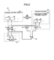
- FIG. 2 is a block diagram illustrating the control system of the nuclear facility according to the embodiment.
- the nuclear facility 1 thus configured includes the control system 40 that controls operations of the various pumps and each equipment such as a valve (not illustrated) disposed at the nuclear facility 1.
- This control system 40 includes a central control facility 41 in ordinary use, an emergency central control facility 43 for emergency, and a plant control facility 42.
- the central control facility 41 is able to control an operation of the nuclear facility 1.
- the emergency central control facility 43 is able to control an operation of the nuclear facility 1.
- the plant control facility 42 is coupled to the central control facility 41 and the emergency central control facility 43.
- the central control facility 41 and the emergency central control facility 43 are so-called digital facilities where arithmetic devices such as a CPU and storage devices such as an HDD are mounted, and are facilities that execute various programs stored in the storage devices by the arithmetic devices so as to control the nuclear facility 1.
- the central control facility 41 includes a plurality of control devices (first operation control devices) 45 that control operations of the nuclear facility 1.
- Each control device 45 is a touch screen input device that integrally includes a display device, which displays an operating condition of the nuclear facility 1 on an operation screen, and an operating device for operating the nuclear facility 1 on the operation screen.
- This touch screen input device is what is called a VDU (Visual Display Unit).
- An operator to operate the nuclear facility 1 visibly recognizes the display device in each control device 45, and obtains the operating condition of the nuclear facility 1. The operator operates the operating device as necessary to control the operation of the nuclear facility 1.
- the emergency central control facility 43 is used in case of emergency such as fire in the nuclear facility 1 and the central control facility 41 becomes unavailable.
- the emergency central control facility 43 includes an emergency control device (a second operation control device) 46 that controls an operation of the nuclear facility 1.
- a plurality of emergency control devices 46 are disposed corresponding to the plurality of control devices 45.
- Each emergency control device 46 is referred to as an evacuation panel, and is configured almost similarly to the central control facility 41.
- the emergency control device 46 integrally includes a display device, which displays an operating condition of the nuclear facility 1 on an emergency operation screen, and an operating device for operating the nuclear facility 1 on the emergency operation screen.
- the plant control facility (a control device) 42 controls operations of the nuclear reactor 5 and each equipment of the nuclear facility 1 based on a signal input to/output from the central control facility 41 and the emergency central control facility 43.
- the plant control facility 42 includes a plurality of process circuits (processing devices) 48 that process signals input to/output from the respective control devices 45.
- the respective process circuits 48 each function as what is called a VDU processor.
- Each process circuit 48 is allowed to be coupled to the control device 45 and the emergency control device 46, and is also configured to process a signal input to/output from the emergency control device 46.
- the nuclear facility 1 includes an evacuation area E1 and a non-evacuation area E2 other than the evacuation area E1.
- an emergency such as fire occurs in the nuclear facility 1
- the operator evacuates from the non-evacuation area E2 to the evacuation area E1 through an evacuation route.
- the central control facility 41 described above is disposed in the non-evacuation area E2 while the emergency central control facility 43 described above is disposed in the evacuation area E1.
- the control system 40 of the nuclear facility 1 includes a configuration to switch from the control device 45 that the operator operates before the evacuation to the emergency control device 46 that the operator operates after the evacuation.
- the following specifically describes the control system 40 of the nuclear facility 1 that includes a signal switching unit 51, a first selector switch 52, a second selector switch 53, and an AND circuit 54.
- a plurality of signal switching units 51 are disposed corresponding to the plurality of control devices 45.
- Each signal switching unit 51 is configured to switch: a normal coupling between the plant control facility 42 and the central control device 41, and an emergency coupling between the plant control facility 42 and the emergency central control device 43.
- Each signal switching unit 51 holds the normal coupling in the case where an emergency switch signal is not input from the AND circuit 54, and each signal switching unit 51 switches from the normal coupling to the emergency coupling in the case where the emergency switch signal is input from the AND circuit 54.
- the first selector switch 52 is disposed on the evacuation route in the non-evacuation area E2, and coupled to the input side of the AND circuit 54. This first selector switch 52 is switchable between the normal coupling side and the emergency coupling side. A switching operation from the normal coupling side to the emergency coupling side by the operator outputs the emergency switch signal from the first selector switch 52 to the AND circuit 54.
- the second selector switch 53 is disposed in the evacuation area E1, and coupled to the input side of the AND circuit 54. This second selector switch 53 is also, similarly to the first selector switch 52, switchable between the normal coupling side and the emergency coupling side. A switching operation from the normal coupling side to the emergency coupling side by the operator outputs the emergency switch signal from the second selector switch 53 to the AND circuit 54.
- the AND circuit 54 has the input side coupled to the first selector switch 52 and the second selector switch 53 while the AND circuit 54 has the output side coupled to the respective signal switching units 51.
- the AND circuit 54 receives the emergency switch signal from the first selector switch 52 and receives the emergency switch signal from the second selector switch 53
- the AND circuit 54 outputs the emergency switch signal to the respective signal switching units 51.
- the AND circuit 54 does not receive the emergency switch signal from at least any one of the first selector switch 52 and the second selector switch 53, the emergency switch signal is not output to the respective signal switching units 51.
- the AND circuit 54 receives the emergency switch signals from the first selector switch 52 and the second selector switch 53. In view of this, the AND circuit 54 outputs emergency switch signals to the plurality of signal switching units 51.
- the respective signal switching units 51 which receive the emergency switch signal, switch from the normal coupling to the emergency coupling.
- the respective process circuits 48 in the normal coupling processes the signals that are input to/output from the respective control devices 45 via the respective signal switching units 51. After switching to the emergency coupling, the respective process circuits 48 process the signals input to/output from the respective emergency control devices 46 via the respective signal switching units 51.
- the above-described configuration operates the first selector switch 52 and the second selector switch 53 to switch from the normal coupling to the emergency coupling. This facilitates collectively switching the operation with the respective control devices 45 to the operation with the respective emergency control devices 46. This consequently allows reducing operation burden on the operator during the operation of collective switching, compared with collective switching with the analog equipment. If the AND circuit 54 does not receive the emergency switch signal from the first selector switch 52 and the second selector switch 53, the AND circuit 54 does not output the emergency switch signal to the signal switching unit 51. In view of this, even if the incorrect operation, short circuit, or similar trouble makes any one of the first selector switch 52 and the second selector switch 53 to output the emergency switch signal, the AND circuit 54 does not output the emergency switch signal. This consequently ensures reduced occurrence of incorrect switching.
- the process circuit 48 is configured to process the signals input to/output from the control device 45 and the emergency control device 46. This allows the control device 45 and the emergency control device 46 to share the process circuit 48. This eliminates the need for a newly added process circuit 48 in the plant control facility 42, and does not significantly change the configuration of the plant control facility 42. Accordingly, the plant control facility 42 allows easily reducing cost escalation of the facility.
- process circuit 48 is disposed inside of the plant control facility 42
- process circuit 48 may be disposed outside of the plant control facility 42.
- the signal switching unit 51 may be disposed inside or outside of the plant control facility 42.
- FIG. 3 is a block diagram illustrating a first selector switch and a second selector switch according to Modification 1. While in the following description a description will be given of the first selector switch 52 to which the configuration according to Modification 1 is applied, this configuration may be applied to the second selector switch 53.
- the first selector switch 52 includes a first operating unit 61, a second operating unit 62, and an OR circuit 63.
- the first operating unit 61 is configured to be switchable between a normal coupling side and an emergency coupling side. A switching operation from the normal coupling side to the emergency coupling side by an operator outputs an emergency switch signal from the first operating unit 61 to the OR circuit 63.
- the second operating unit 62 is configured, similarly to the first operating unit 61, to be switchable between the normal coupling side and the emergency coupling side. A switching operation from the normal coupling side to the emergency coupling side by the operator outputs the emergency switch signal from the second operating unit 62 to the OR circuit 63.
- the OR circuit 63 has an input side coupled to the first operating unit 61 and the second operating unit 62 while the OR circuit 63 has an output side coupled to the AND circuit 54. In the case where the OR circuit 63 receives an emergency coupling signal from at least any one of the first operating unit 61 and the second operating unit 62, the OR circuit 63 outputs the emergency switch signal to the AND circuit 54.
- control system for the nuclear facility is effective for a nuclear facility where an operator is assumed to evacuate to an evacuation area.
- control system for the nuclear facility is appropriate for a case where operations of the nuclear facility are operated in the evacuation area.
Landscapes
- Physics & Mathematics (AREA)
- Engineering & Computer Science (AREA)
- Business, Economics & Management (AREA)
- Emergency Management (AREA)
- Plasma & Fusion (AREA)
- General Engineering & Computer Science (AREA)
- High Energy & Nuclear Physics (AREA)
- Testing And Monitoring For Control Systems (AREA)
- Safety Devices In Control Systems (AREA)
- Monitoring And Testing Of Nuclear Reactors (AREA)
Abstract
Description
- The present invention relates to a control system for a nuclear facility that allows controlling an operation of the nuclear facility within an evacuation area for evacuation when an emergency occurs.
- Conventionally, a known remote shutdown system includes a central control room control panel, a remote shutdown panel, an on-site multiple transmission device panel, and a mode selection switch (for example, see Patent Literature 1). The central control room control panel is disposed within a central control room and remotely controls a nuclear reactor. The remote shutdown panel is disposed outside of the central control room and remotely shuts down the nuclear reactor. The on-site multiple transmission device panel controls a plurality of loads at the nuclear reactor. Here, the mode selection switch provides either one of two couplings of a coupling between the central control room control panel and the on-site multiple transmission device panel or a coupling between the remote shutdown panel and the on-site multiple transmission device panel.
- Patent Literature 1: Japanese Patent Application Laid-open No.
59-174787 - The conventional remote shutdown system has a mode selection switch that is an analog circuit switch with a contact point. Therefore, to collectively perform switching operations, coaxial cables are necessary to be disposed as multiplex transmission lines between the central control room control panel and the on-site multiple transmission device panel and between the remote shutdown panel and the on-site multiple transmission device panel. Accordingly, in the case where switching operations are collectively performed, a control circuit or a control device for multiple transmission is necessary to be separately added around the mode selection switch. That is, although the conventional remote shutdown system can collectively perform switching operations with analog equipment, the analog equipment differs from the central control room control panel in operation. Accordingly, this imposes burden on an operator. An incorrect operation of the mode selection switch or short circuit of the mode selection switch due to failure, fire spread, or similar trouble, may cause an incorrect switching operation where a coupling is unintentionally switched.
- Therefore, it is an object of the present invention to provide a control system for a nuclear facility that facilitates switching operation between the operation control devices and reduces incorrect switching operations.
- According to an aspect of a control system for a nuclear facility of the present invention, the control system for a nuclear facility that allows controlling an operation of a nuclear facility in an evacuation area for evacuation when an emergency occurs, the control system includes: a first operation control device for ordinary use, the first operation control device being disposed in a non-evacuation area, the non-evacuation area being an area other than the evacuation area; a second operation control device for emergency, the second operation control device being disposed in the evacuation area; a control device connectable to the first operation control device or the second operation control device; a signal switching unit configured to switch from a normal coupling between the control device and the first operation control device to an emergency coupling between the control device and the second operation control device based on an emergency switch signal to be input; a first selector switch disposed in the non-evacuation area, the first selector switch being configured to output an emergency switch signal by a switching operation to the emergency coupling; a second selector switch disposed in the evacuation area, the second selector switch being configured to output an emergency switch signal by a switching operation to the emergency coupling; and an AND circuit with an input side and an output side, the input side being coupled to the first selector switch and the second selector switch, the output side being coupled to the signal switching unit, wherein the AND circuit is configured to output the emergency switch signal to the signal switching unit in a case where the emergency switch signal is input from the first selector switch and the emergency switch signal is input from the second selector switch.
- With this configuration, operating the first selector switch and the second selector switch to switch from the normal coupling to the emergency coupling facilitates collective switching from an operation with the first operation control device to an operation with the second operation control device. Additionally, switching the first selector switch to the emergency coupling side and switching the second selector switch to the emergency coupling side allow inputting the emergency switch signals to an AND circuit from the first selector switch and the second selector switch. This allows the AND circuit to output the emergency switch signal to the signal switching unit. In view of this, the signal switching unit receives the emergency switch signal and is allowed to switch from the normal coupling to the emergency coupling. Therefore, even if one of the first selector switch and the second selector switch incorrectly outputs the emergency switch signal, the AND circuit does not output the emergency switch signal. This consequently ensures reduced occurrence of incorrect switching between the operation control devices.
- According to the aspect, it is preferable that the control device includes a processing device coupled to the signal switching unit, and the processing device is configured to: process a signal input to/output from the first operation control device through the signal switching unit; and process a signal input to/output from the second operation control device through the signal switching unit.
- This configuration allows the first operation control device and the second operation control device to share the processing device. This eliminates the need for an additional processing device, thus reducing cost escalation of the device.
- According to the aspect, it is preferable that at least any one of the first selector switch and the second selector switch includes: a first operating unit configured to output the emergency switch signal by a switching operation to the emergency coupling; a second operating unit configured to output the emergency switch signal by a switching operation to the emergency coupling; and an OR circuit with an input side and an output side, the input side being coupled to the first operating unit and the second operating unit, the output side being coupled to the AND circuit, wherein the OR circuit is configured to output the emergency switch signal to the AND circuit in a case where the emergency switch signal is input from at least any one of the first operating unit and the second operating unit.
- With this configuration, switching any one of the first operating unit and the second operating unit to the emergency coupling side allows inputting the emergency switch signal to the OR circuit. This allows the OR circuit to output the emergency switch signal to the AND circuit. In view of this, even if any one of the first operating unit and the second operating unit is not able to output the emergency switch signal due to disconnection or similar trouble, this allows outputting the emergency switch signal as long as the other operating unit can output the emergency switch signal.
-
-
FIG. 1 is a schematic configuration diagram schematically illustrating a nuclear facility controlled by a control system according to an embodiment. -
FIG. 2 is a block diagram illustrating the control system of the nuclear facility according to the embodiment. -
FIG. 3 is a block diagram illustrating a first selector switch and a second selector switch according to Modification 1. - Hereinafter, a description will be given of a control system for a nuclear facility according to the present invention by referring to the accompanying drawings. The following embodiment does not limit the present invention. Further, components in the following embodiment include components that can be easily conceived by a person skilled in the art or substantially the same components Embodiment
-
FIG. 1 is a schematic configuration diagram schematically illustrating a nuclear facility controlled by a control system according to an embodiment. Acontrol system 40 for a nuclear facility 1 according to the present invention controls the nuclear facility 1 with anuclear reactor 5. Thenuclear reactor 5 employs, for example, a Pressurized Water Reactor (PWR). The nuclear facility 1 with this pressurized waternuclear reactor 5 includes areactor cooling system 3 that includes thenuclear reactor 5 and a turbine system 4 that exchanges heat with thereactor cooling system 3. A reactor coolant flows in thereactor cooling system 3 while a secondary coolant flows in the turbine system 4. - The
reactor cooling system 3 includes thenuclear reactor 5 and asteam generator 7, which is coupled to thenuclear reactor 5 via acold leg 6a and ahot leg 6b. A pressurizer 8 is interposed in thehot leg 6b while areactor coolant pump 9 is interposed in thecold leg 6a. Then, thenuclear reactor 5, thecold leg 6a, thehot leg 6b, thesteam generator 7, the pressurizer 8, and thereactor coolant pump 9 are housed in acontainment 10. - The
nuclear reactor 5, which is a pressurized water reactor as described above, is filled with the reactor coolant inside. In thenuclear reactor 5, afuel assembly 15 is housed andmultiple control rods 16, which control the nuclear fission of thefuel assembly 15, are removably inserted into thefuel assembly 15. - In the case where the
fuel assembly 15 is made to fission while the nuclear fission reaction is controlled by thecontrol rod 16, this nuclear fission provides heat energy. The provided heat energy heats the reactor coolant. The heated reactor coolant is fed to thesteam generator 7 via thehot leg 6b. On the other hand, the reactor coolant is fed from thesteam generator 7 via thecold leg 6a and flows through thenuclear reactor 5 to cool the inside of thenuclear reactor 5. - The pressurizer 8 interposed in the
hot leg 6b applies pressure on the reactor coolant at high temperature to reduce boiling of the reactor coolant. Additionally, thesteam generator 7 makes the reactor coolant at high temperature and high pressure to exchange heat with the secondary coolant. This consequently vaporizes the secondary coolant to generate vapor and cools the reactor coolant at high temperature and high pressure. Thereactor coolant pump 9 circulates the reactor coolant in thereactor cooling system 3. Thereactor coolant pump 9 feeds the reactor coolant into thenuclear reactor 5 from thesteam generator 7 via thecold leg 6a, and feeds the reactor coolant into eachsteam generator 7 from thenuclear reactor 5 via thehot leg 6b. - Here, a description will be given of a sequence of operations in the
reactor cooling system 3 of the nuclear facility 1. When the reactor coolant is heated with the heat energy generated by the nuclear fission reaction inside of thenuclear reactor 5, thereactor coolant pump 9 feeds the heated reactor coolant to thesteam generator 7 via thehot leg 6b. The high-temperature reactor coolant passing through thehot leg 6b receives pressure from the pressurizer 8 to reduce boiling, and flows into thesteam generator 7 at high temperature and high pressure. The reactor coolant after flowing into thesteam generator 7 at high temperature and high pressure is cooled by exchanging heat with the secondary coolant. The cooled reactor coolant is fed to thenuclear reactor 5 via thecold leg 6a by thereactor coolant pump 9. Then, the cooled reactor coolant flows into thenuclear reactor 5 so as to cool thenuclear reactor 5. That is, the reactor coolant circulates between thenuclear reactor 5 and thesteam generator 7. The reactor coolant is light water used as a coolant and a neutron moderator. - The turbine system 4 includes a
turbine 22, which is coupled to thesteam generator 7 via asteam pipe 21, a condenser 23, which is coupled to theturbine 22, and afeed pump 24, which is interposed in awater supply pipe 26 that couples the condenser 23 and thesteam generator 7. Additionally, anelectric generator 25 is coupled to the above-describedturbine 22. - Here, a description will be given of a sequence of operations in the turbine system 4 of the nuclear facility 1. The vapor flowing from the
steam generator 7 via thesteam pipe 21 into theturbine 22 makes theturbine 22 to rotate. The rotation of theturbine 22 makes theelectric generator 25, which is coupled to theturbine 22, to generate electricity. Subsequently, the vapor that flows out from theturbine 22 flows into the condenser 23. The condenser 23 has a coolingpipe 27 inside. The coolingpipe 27 has one side coupled to anintake pipe 28 to supply cooling water (such as seawater) while the coolingpipe 27 has another side coupled to adischarge pipe 29 to discharge the cooling water. Then, the condenser 23 cools the vapor, which flows in from theturbine 22, with the coolingpipe 27 to transform the vapor back to liquid. The liquid secondary coolant is fed to thesteam generator 7 via thewater supply pipe 26 by thefeed pump 24. The secondary coolant fed to thesteam generator 7 is transformed into vapor again by heat exchange with the reactor coolant in thesteam generator 7. -
FIG. 2 is a block diagram illustrating the control system of the nuclear facility according to the embodiment. The nuclear facility 1 thus configured includes thecontrol system 40 that controls operations of the various pumps and each equipment such as a valve (not illustrated) disposed at the nuclear facility 1. Thiscontrol system 40 includes acentral control facility 41 in ordinary use, an emergencycentral control facility 43 for emergency, and aplant control facility 42. Thecentral control facility 41 is able to control an operation of the nuclear facility 1. The emergencycentral control facility 43 is able to control an operation of the nuclear facility 1. Theplant control facility 42 is coupled to thecentral control facility 41 and the emergencycentral control facility 43. Thecentral control facility 41 and the emergencycentral control facility 43 are so-called digital facilities where arithmetic devices such as a CPU and storage devices such as an HDD are mounted, and are facilities that execute various programs stored in the storage devices by the arithmetic devices so as to control the nuclear facility 1. - The
central control facility 41 includes a plurality of control devices (first operation control devices) 45 that control operations of the nuclear facility 1. Eachcontrol device 45 is a touch screen input device that integrally includes a display device, which displays an operating condition of the nuclear facility 1 on an operation screen, and an operating device for operating the nuclear facility 1 on the operation screen. This touch screen input device is what is called a VDU (Visual Display Unit). An operator to operate the nuclear facility 1 visibly recognizes the display device in eachcontrol device 45, and obtains the operating condition of the nuclear facility 1. The operator operates the operating device as necessary to control the operation of the nuclear facility 1. - The emergency
central control facility 43 is used in case of emergency such as fire in the nuclear facility 1 and thecentral control facility 41 becomes unavailable. The emergencycentral control facility 43 includes an emergency control device (a second operation control device) 46 that controls an operation of the nuclear facility 1. A plurality ofemergency control devices 46 are disposed corresponding to the plurality ofcontrol devices 45. Eachemergency control device 46 is referred to as an evacuation panel, and is configured almost similarly to thecentral control facility 41. Theemergency control device 46 integrally includes a display device, which displays an operating condition of the nuclear facility 1 on an emergency operation screen, and an operating device for operating the nuclear facility 1 on the emergency operation screen. - The plant control facility (a control device) 42 controls operations of the
nuclear reactor 5 and each equipment of the nuclear facility 1 based on a signal input to/output from thecentral control facility 41 and the emergencycentral control facility 43. Theplant control facility 42 includes a plurality of process circuits (processing devices) 48 that process signals input to/output from therespective control devices 45. Therespective process circuits 48 each function as what is called a VDU processor. Eachprocess circuit 48 is allowed to be coupled to thecontrol device 45 and theemergency control device 46, and is also configured to process a signal input to/output from theemergency control device 46. - The nuclear facility 1 includes an evacuation area E1 and a non-evacuation area E2 other than the evacuation area E1. In the case where an emergency such as fire occurs in the nuclear facility 1, the operator evacuates from the non-evacuation area E2 to the evacuation area E1 through an evacuation route. Here, the
central control facility 41 described above is disposed in the non-evacuation area E2 while the emergencycentral control facility 43 described above is disposed in the evacuation area E1. In view of this, when an emergency occurs, the operator uses the emergencycentral control facility 43 disposed in the evacuation area E1 to control the operation of the nuclear facility 1. At this time, thecontrol system 40 of the nuclear facility 1 includes a configuration to switch from thecontrol device 45 that the operator operates before the evacuation to theemergency control device 46 that the operator operates after the evacuation. The following specifically describes thecontrol system 40 of the nuclear facility 1 that includes asignal switching unit 51, afirst selector switch 52, asecond selector switch 53, and an ANDcircuit 54. - A plurality of
signal switching units 51 are disposed corresponding to the plurality ofcontrol devices 45. Eachsignal switching unit 51 is configured to switch: a normal coupling between theplant control facility 42 and thecentral control device 41, and an emergency coupling between theplant control facility 42 and the emergencycentral control device 43. Eachsignal switching unit 51 holds the normal coupling in the case where an emergency switch signal is not input from the ANDcircuit 54, and eachsignal switching unit 51 switches from the normal coupling to the emergency coupling in the case where the emergency switch signal is input from the ANDcircuit 54. - The
first selector switch 52 is disposed on the evacuation route in the non-evacuation area E2, and coupled to the input side of the ANDcircuit 54. Thisfirst selector switch 52 is switchable between the normal coupling side and the emergency coupling side. A switching operation from the normal coupling side to the emergency coupling side by the operator outputs the emergency switch signal from thefirst selector switch 52 to the ANDcircuit 54. - The
second selector switch 53 is disposed in the evacuation area E1, and coupled to the input side of the ANDcircuit 54. Thissecond selector switch 53 is also, similarly to thefirst selector switch 52, switchable between the normal coupling side and the emergency coupling side. A switching operation from the normal coupling side to the emergency coupling side by the operator outputs the emergency switch signal from thesecond selector switch 53 to the ANDcircuit 54. - The AND
circuit 54 has the input side coupled to thefirst selector switch 52 and thesecond selector switch 53 while the ANDcircuit 54 has the output side coupled to the respectivesignal switching units 51. In the case where the ANDcircuit 54 receives the emergency switch signal from thefirst selector switch 52 and receives the emergency switch signal from thesecond selector switch 53, the ANDcircuit 54 outputs the emergency switch signal to the respectivesignal switching units 51. In other words, if the ANDcircuit 54 does not receive the emergency switch signal from at least any one of thefirst selector switch 52 and thesecond selector switch 53, the emergency switch signal is not output to the respectivesignal switching units 51. - Here, a description will be given of a sequence of operations to switch from the normal coupling to the emergency coupling in the
control system 40 of the nuclear facility 1. In the case where an emergency occurs in the nuclear facility 1, the operator that has been operating thecentral control facility 41 moves from the non-evacuation area E2 to the evacuation area E1 through the evacuation route. At this time, the operator performs the switching operation of thefirst selector switch 52, which is disposed on the evacuation route, from the normal coupling side to the emergency coupling side. Subsequently, the operator who has moved to the evacuation area E1 performs the switching operation of thesecond selector switch 53, which is disposed in the evacuation area E1, from the normal coupling side to the emergency coupling side. - The AND
circuit 54 receives the emergency switch signals from thefirst selector switch 52 and thesecond selector switch 53. In view of this, the ANDcircuit 54 outputs emergency switch signals to the plurality ofsignal switching units 51. The respectivesignal switching units 51, which receive the emergency switch signal, switch from the normal coupling to the emergency coupling. In view of this, therespective process circuits 48 in the normal coupling processes the signals that are input to/output from therespective control devices 45 via the respectivesignal switching units 51. After switching to the emergency coupling, therespective process circuits 48 process the signals input to/output from the respectiveemergency control devices 46 via the respectivesignal switching units 51. - The above-described configuration operates the
first selector switch 52 and thesecond selector switch 53 to switch from the normal coupling to the emergency coupling. This facilitates collectively switching the operation with therespective control devices 45 to the operation with the respectiveemergency control devices 46. This consequently allows reducing operation burden on the operator during the operation of collective switching, compared with collective switching with the analog equipment. If the ANDcircuit 54 does not receive the emergency switch signal from thefirst selector switch 52 and thesecond selector switch 53, the ANDcircuit 54 does not output the emergency switch signal to thesignal switching unit 51. In view of this, even if the incorrect operation, short circuit, or similar trouble makes any one of thefirst selector switch 52 and thesecond selector switch 53 to output the emergency switch signal, the ANDcircuit 54 does not output the emergency switch signal. This consequently ensures reduced occurrence of incorrect switching. - The
process circuit 48 is configured to process the signals input to/output from thecontrol device 45 and theemergency control device 46. This allows thecontrol device 45 and theemergency control device 46 to share theprocess circuit 48. This eliminates the need for a newly addedprocess circuit 48 in theplant control facility 42, and does not significantly change the configuration of theplant control facility 42. Accordingly, theplant control facility 42 allows easily reducing cost escalation of the facility. - While in this embodiment the
process circuit 48 is disposed inside of theplant control facility 42, theprocess circuit 48 may be disposed outside of theplant control facility 42. Thesignal switching unit 51 may be disposed inside or outside of theplant control facility 42. - Furthermore, while in this embodiment the
first selector switch 52 and thesecond selector switch 53 are configured to be switchable between the normal coupling side and the emergency coupling side, a configuration of Modification 1 illustrated inFIG. 3 may be possible. Here,FIG. 3 is a block diagram illustrating a first selector switch and a second selector switch according to Modification 1. While in the following description a description will be given of thefirst selector switch 52 to which the configuration according to Modification 1 is applied, this configuration may be applied to thesecond selector switch 53. - As illustrated in
FIG. 3 , thefirst selector switch 52 includes afirst operating unit 61, asecond operating unit 62, and anOR circuit 63. Thefirst operating unit 61 is configured to be switchable between a normal coupling side and an emergency coupling side. A switching operation from the normal coupling side to the emergency coupling side by an operator outputs an emergency switch signal from thefirst operating unit 61 to theOR circuit 63. Thesecond operating unit 62 is configured, similarly to thefirst operating unit 61, to be switchable between the normal coupling side and the emergency coupling side. A switching operation from the normal coupling side to the emergency coupling side by the operator outputs the emergency switch signal from thesecond operating unit 62 to theOR circuit 63. - The OR
circuit 63 has an input side coupled to thefirst operating unit 61 and thesecond operating unit 62 while theOR circuit 63 has an output side coupled to the ANDcircuit 54. In the case where theOR circuit 63 receives an emergency coupling signal from at least any one of thefirst operating unit 61 and thesecond operating unit 62, theOR circuit 63 outputs the emergency switch signal to the ANDcircuit 54. - With the configuration of Modification 1, switching any one of the
first operating unit 61 and thesecond operating unit 62 to the emergency coupling side allows inputting the emergency switch signal to theOR circuit 63. This allows theOR circuit 63 to output the emergency switch signal to the ANDcircuit 54. In view of this, even if any one of thefirst operating unit 61 and thesecond operating unit 62 is not able to output the emergency switch signal due to disconnection and similar trouble, this consequently allows outputting the emergency switch signal as long as the other operating unit is able to output the emergency switch signal. - As described above, the control system for the nuclear facility according to the present invention is effective for a nuclear facility where an operator is assumed to evacuate to an evacuation area. Especially, the control system for the nuclear facility is appropriate for a case where operations of the nuclear facility are operated in the evacuation area.
-
- 1
- nuclear facility
- 3
- reactor cooling system
- 4
- turbine system
- 5
- nuclear reactor
- 7
- steam generator
- 8
- pressurizer
- 9
- reactor coolant pump
- 15
- fuel assembly
- 16
- control rod
- 22
- turbine
- 23
- condenser
- 25
- electric generator
- 27
- cooling pipe
- 28
- intake pipe
- 29
- discharge pipe
- 40
- control system
- 41
- central control facility
- 42
- plant control facility
- 43
- emergency central control facility
- 45
- control device
- 46
- emergency control device
- 48
- process circuit
- 51
- signal switching unit
- 52
- first selector switch
- 53
- second selector switch
- 54
- AND circuit
- 61
- first operating unit
- 62
- second operating unit
- 63
- OR circuit
- E1
- evacuation area
- E2
- non-evacuation area
Claims (3)
- A control system for a nuclear facility that allows controlling an operation of a nuclear facility in an evacuation area for evacuation when an emergency occurs, the control system comprising:a first operation control device for ordinary use, the first operation control device being disposed in a non-evacuation area, the non-evacuation area being an area other than the evacuation area;a second operation control device for emergency, the second operation control device being disposed in the evacuation area;a control device connectable to the first operation control device or the second operation control device;a signal switching unit configured to switch from a normal coupling between the control device and the first operation control device to an emergency coupling between the control device and the second operation control device based on an emergency switch signal to be input;a first selector switch disposed in the non-evacuation area, the first selector switch being configured to output an emergency switch signal by a switching operation to the emergency coupling;a second selector switch disposed in the evacuation area, the second selector switch being configured to output an emergency switch signal by a switching operation to the emergency coupling; andan AND circuit with an input side and an output side, the input side being coupled to the first selector switch and the second selector switch, the output side being coupled to the signal switching unit, whereinthe AND circuit is configured to output the emergency switch signal to the signal switching unit in a case where the emergency switch signal is input from the first selector switch and the emergency switch signal is input from the second selector switch.
- The control system for the nuclear facility according to claim 1, wherein
the control device includes a processing device coupled to the signal switching unit, and
the processing device is configured to: process a signal input to/output from the first operation control device through the signal switching unit; and process a signal input to/output from the second operation control device through the signal switching unit. - The control system for the nuclear facility according to claim 1 or 2, wherein
at least any one of the first selector switch and the second selector switch includes:a first operating unit configured to output the emergency switch signal by a switching operation to the emergency coupling;a second operating unit configured to output the emergency switch signal by a switching operation to the emergency coupling; andan OR circuit with an input side and an output side, the input side being coupled to the first operating unit and the second operating unit, the output side being coupled to the AND circuit, whereinthe OR circuit is configured to output the emergency switch signal to the AND circuit in a case where the emergency switch signal is input from at least any one of the first operating unit and the second operating unit.
Applications Claiming Priority (2)
| Application Number | Priority Date | Filing Date | Title |
|---|---|---|---|
| JP2010230078A JP5606260B2 (en) | 2010-10-12 | 2010-10-12 | Nuclear facility control system |
| PCT/JP2011/070904 WO2012049936A1 (en) | 2010-10-12 | 2011-09-13 | Nuclear power facility control system |
Publications (2)
| Publication Number | Publication Date |
|---|---|
| EP2629302A1 true EP2629302A1 (en) | 2013-08-21 |
| EP2629302A4 EP2629302A4 (en) | 2017-05-10 |
Family
ID=45938169
Family Applications (1)
| Application Number | Title | Priority Date | Filing Date |
|---|---|---|---|
| EP11832374.0A Withdrawn EP2629302A4 (en) | 2010-10-12 | 2011-09-13 | Nuclear power facility control system |
Country Status (4)
| Country | Link |
|---|---|
| US (1) | US9685246B2 (en) |
| EP (1) | EP2629302A4 (en) |
| JP (1) | JP5606260B2 (en) |
| WO (1) | WO2012049936A1 (en) |
Cited By (1)
| Publication number | Priority date | Publication date | Assignee | Title |
|---|---|---|---|---|
| CN111798999A (en) * | 2020-06-04 | 2020-10-20 | 江苏核电有限公司 | Method for reducing switch failure rate of electric heater of voltage stabilizer in nuclear power plant |
Families Citing this family (4)
| Publication number | Priority date | Publication date | Assignee | Title |
|---|---|---|---|---|
| JP2016118990A (en) * | 2014-12-22 | 2016-06-30 | 株式会社東芝 | Plant monitoring control system and plant system |
| JP6636902B2 (en) * | 2016-11-29 | 2020-01-29 | 株式会社東芝 | Nuclear power plant system and training method using the same |
| JP6822992B2 (en) * | 2018-02-28 | 2021-01-27 | 日立Geニュークリア・エナジー株式会社 | Central control outdoor reactor shutdown system |
| JP7391244B2 (en) * | 2020-11-30 | 2023-12-04 | 三菱電機株式会社 | control switching device |
Family Cites Families (13)
| Publication number | Priority date | Publication date | Assignee | Title |
|---|---|---|---|---|
| JPS5447983A (en) * | 1977-09-22 | 1979-04-16 | Toshiba Corp | Device for stopping atomic power plant |
| JPS55101398U (en) * | 1979-01-08 | 1980-07-15 | ||
| JPS55101398A (en) | 1979-01-19 | 1980-08-02 | Nippon Riken Kagaku Kk | Method of reinforcing drilling portion and drilling machine with device for attaching reinforcing material |
| JPS57211596A (en) * | 1981-06-24 | 1982-12-25 | Tokyo Shibaura Electric Co | Automatically switching circuit of remote operation stop device |
| JPS58158595A (en) * | 1982-03-16 | 1983-09-20 | 株式会社東芝 | Control device of reactor shutdown circuit |
| JPS59174787A (en) * | 1983-03-25 | 1984-10-03 | 株式会社東芝 | Reactor shutdown device away from central control room |
| JPS59190696A (en) * | 1983-04-13 | 1984-10-29 | 株式会社東芝 | Remote control system of atomic power plant |
| JPS59231488A (en) * | 1983-06-15 | 1984-12-26 | 株式会社日立製作所 | Nuclear reactor remote shutdown device |
| JPS60151599A (en) * | 1984-01-19 | 1985-08-09 | 株式会社東芝 | Remote control system of nuclear power plant |
| JPH0312595A (en) * | 1989-06-09 | 1991-01-21 | Toshiba Corp | Nuclear reactor stopping device outside central control room |
| JPH05333195A (en) * | 1992-06-03 | 1993-12-17 | Toshiba Corp | Remote reactor shutdown device |
| KR100408493B1 (en) * | 2001-05-07 | 2003-12-06 | 한국전력기술 주식회사 | System for digital reactor protecting to prevent common mode failures and control method of the same |
| TW201028306A (en) | 2009-01-22 | 2010-08-01 | Chiang Pen Petrochemical Transp Corp | Safety interconnection device for oil tank car |
-
2010
- 2010-10-12 JP JP2010230078A patent/JP5606260B2/en active Active
-
2011
- 2011-09-13 WO PCT/JP2011/070904 patent/WO2012049936A1/en not_active Ceased
- 2011-09-13 EP EP11832374.0A patent/EP2629302A4/en not_active Withdrawn
- 2011-09-13 US US13/877,233 patent/US9685246B2/en active Active
Cited By (2)
| Publication number | Priority date | Publication date | Assignee | Title |
|---|---|---|---|---|
| CN111798999A (en) * | 2020-06-04 | 2020-10-20 | 江苏核电有限公司 | Method for reducing switch failure rate of electric heater of voltage stabilizer in nuclear power plant |
| CN111798999B (en) * | 2020-06-04 | 2021-11-09 | 江苏核电有限公司 | Method for reducing switch failure rate of electric heater of voltage stabilizer in nuclear power plant |
Also Published As
| Publication number | Publication date |
|---|---|
| US20130202074A1 (en) | 2013-08-08 |
| JP2012083232A (en) | 2012-04-26 |
| US9685246B2 (en) | 2017-06-20 |
| EP2629302A4 (en) | 2017-05-10 |
| WO2012049936A1 (en) | 2012-04-19 |
| JP5606260B2 (en) | 2014-10-15 |
Similar Documents
| Publication | Publication Date | Title |
|---|---|---|
| US9589683B2 (en) | Reactor shutdown system | |
| US9685246B2 (en) | Control system for nuclear facility and control method for nuclear facility | |
| EP2629301B1 (en) | Control system for nuclear power facility | |
| CN102638095B (en) | A kind of method of supplying power to of nuclear power plant cold-state function test | |
| EP2495730B1 (en) | Nuclear power plant and operational support method for nuclear power plant | |
| EP2602794B1 (en) | Control system for nuclear power plant | |
| EP2884496B1 (en) | Nuclear reactor monitoring device, nuclear reactor control device, and nuclear power generation plant | |
| JP2016508216A (en) | Power management for nuclear reactor systems | |
| JP2012233705A (en) | Monitoring control system of nuclear power plant | |
| JP6444098B2 (en) | Monitoring and control equipment for nuclear power plants | |
| US9558856B2 (en) | Control system for plant | |
| JP2019148544A (en) | Central control outdoor reactor stop device | |
| KR101771349B1 (en) | Large display panel and method for displaying operation status of nuclear power plant | |
| JP2012233696A (en) | Nuclear power plant | |
| He et al. | Control systems for spallation target in China initiative accelerator driven system | |
| CN110570961A (en) | Method and system for state recovery after loss of single area under thermal shutdown condition of nuclear power unit | |
| Li et al. | Study on the Operating Strategy Optimization of Moving to Remote Shutdown Station When Main Control Room Is Un-Inhabitable | |
| JP5754952B2 (en) | 1/2 primary cooling water system for nuclear power plant and nuclear power plant | |
| WO2016044941A1 (en) | Arrangement and control of thermoelectric power generation cells | |
| Izquierdo et al. | Tests and procedures for optimizing EMIR cooling system |
Legal Events
| Date | Code | Title | Description |
|---|---|---|---|
| PUAI | Public reference made under article 153(3) epc to a published international application that has entered the european phase |
Free format text: ORIGINAL CODE: 0009012 |
|
| 17P | Request for examination filed |
Effective date: 20130329 |
|
| AK | Designated contracting states |
Kind code of ref document: A1 Designated state(s): AL AT BE BG CH CY CZ DE DK EE ES FI FR GB GR HR HU IE IS IT LI LT LU LV MC MK MT NL NO PL PT RO RS SE SI SK SM TR |
|
| DAX | Request for extension of the european patent (deleted) | ||
| RIC1 | Information provided on ipc code assigned before grant |
Ipc: G21D 3/00 20060101ALI20170330BHEP Ipc: G21D 3/04 20060101AFI20170330BHEP |
|
| RA4 | Supplementary search report drawn up and despatched (corrected) |
Effective date: 20170407 |
|
| GRAP | Despatch of communication of intention to grant a patent |
Free format text: ORIGINAL CODE: EPIDOSNIGR1 |
|
| INTG | Intention to grant announced |
Effective date: 20180507 |
|
| STAA | Information on the status of an ep patent application or granted ep patent |
Free format text: STATUS: THE APPLICATION IS DEEMED TO BE WITHDRAWN |
|
| 18D | Application deemed to be withdrawn |
Effective date: 20180918 |