EP2629155A2 - Toner conveying device and image forming apparatus including the same - Google Patents
Toner conveying device and image forming apparatus including the same Download PDFInfo
- Publication number
- EP2629155A2 EP2629155A2 EP13153349.9A EP13153349A EP2629155A2 EP 2629155 A2 EP2629155 A2 EP 2629155A2 EP 13153349 A EP13153349 A EP 13153349A EP 2629155 A2 EP2629155 A2 EP 2629155A2
- Authority
- EP
- European Patent Office
- Prior art keywords
- toner conveying
- pipe
- toner
- conveying
- conveying pipe
- Prior art date
- Legal status (The legal status is an assumption and is not a legal conclusion. Google has not performed a legal analysis and makes no representation as to the accuracy of the status listed.)
- Granted
Links
Images





Classifications
-
- G—PHYSICS
- G03—PHOTOGRAPHY; CINEMATOGRAPHY; ANALOGOUS TECHNIQUES USING WAVES OTHER THAN OPTICAL WAVES; ELECTROGRAPHY; HOLOGRAPHY
- G03G—ELECTROGRAPHY; ELECTROPHOTOGRAPHY; MAGNETOGRAPHY
- G03G15/00—Apparatus for electrographic processes using a charge pattern
- G03G15/06—Apparatus for electrographic processes using a charge pattern for developing
- G03G15/08—Apparatus for electrographic processes using a charge pattern for developing using a solid developer, e.g. powder developer
- G03G15/0822—Arrangements for preparing, mixing, supplying or dispensing developer
- G03G15/0887—Arrangements for conveying and conditioning developer in the developing unit, e.g. agitating, removing impurities or humidity
- G03G15/0891—Arrangements for conveying and conditioning developer in the developing unit, e.g. agitating, removing impurities or humidity for conveying or circulating developer, e.g. augers
-
- B—PERFORMING OPERATIONS; TRANSPORTING
- B65—CONVEYING; PACKING; STORING; HANDLING THIN OR FILAMENTARY MATERIAL
- B65G—TRANSPORT OR STORAGE DEVICES, e.g. CONVEYORS FOR LOADING OR TIPPING, SHOP CONVEYOR SYSTEMS OR PNEUMATIC TUBE CONVEYORS
- B65G33/00—Screw or rotary spiral conveyors
- B65G33/24—Details
- B65G33/32—Adaptations of bearings or couplings for supporting and connecting screws
-
- G—PHYSICS
- G03—PHOTOGRAPHY; CINEMATOGRAPHY; ANALOGOUS TECHNIQUES USING WAVES OTHER THAN OPTICAL WAVES; ELECTROGRAPHY; HOLOGRAPHY
- G03G—ELECTROGRAPHY; ELECTROPHOTOGRAPHY; MAGNETOGRAPHY
- G03G15/00—Apparatus for electrographic processes using a charge pattern
- G03G15/06—Apparatus for electrographic processes using a charge pattern for developing
- G03G15/08—Apparatus for electrographic processes using a charge pattern for developing using a solid developer, e.g. powder developer
- G03G15/0822—Arrangements for preparing, mixing, supplying or dispensing developer
- G03G15/0844—Arrangements for purging used developer from the developing unit
-
- G—PHYSICS
- G03—PHOTOGRAPHY; CINEMATOGRAPHY; ANALOGOUS TECHNIQUES USING WAVES OTHER THAN OPTICAL WAVES; ELECTROGRAPHY; HOLOGRAPHY
- G03G—ELECTROGRAPHY; ELECTROPHOTOGRAPHY; MAGNETOGRAPHY
- G03G21/00—Arrangements not provided for by groups G03G13/00 - G03G19/00, e.g. cleaning, elimination of residual charge
- G03G21/10—Collecting or recycling waste developer
- G03G21/105—Arrangements for conveying toner waste
-
- G—PHYSICS
- G03—PHOTOGRAPHY; CINEMATOGRAPHY; ANALOGOUS TECHNIQUES USING WAVES OTHER THAN OPTICAL WAVES; ELECTROGRAPHY; HOLOGRAPHY
- G03G—ELECTROGRAPHY; ELECTROPHOTOGRAPHY; MAGNETOGRAPHY
- G03G2215/00—Apparatus for electrophotographic processes
- G03G2215/08—Details of powder developing device not concerning the development directly
- G03G2215/0802—Arrangements for agitating or circulating developer material
- G03G2215/0816—Agitator type
- G03G2215/0827—Augers
Definitions
- the present disclosure relates to a toner conveying device used in an image forming apparatus such as a copy machine, a printer, a facsimile, a multifunctional peripheral having functions of these apparatuses, or the like.
- a conventional image forming apparatus generally performs a process in which a powdered developer is mainly used to visualize, by use of a developing device, an electrostatic latent image formed on an image bearing member such as a photosensitive drum or the like, and a visualized image (toner image) thus formed is transferred onto a recording medium and then is subjected to fixing processing.
- Toner remaining on the surface of the image bearing member is removed by a cleaning device, after which a new toner image is formed thereon.
- the residual toner that has been removed by the cleaning device is stored in a waste toner bottle. When the waste toner bottle becomes filled to capacity after a predetermined number of times of printing, a user is notified as such, and the waster toner bottle is discarded to be replaced with a new one.
- a toner conveying path constituted by a pipe-shaped conveying passage including inside thereof a conveying screw.
- this toner conveying path in a case where, due to dimensional tolerances on the outer diameter of the conveying screw and on the inner diameter of the conveying passage, warping of the conveying screw, or the like, a trajectory of an outer peripheral edge of the conveying screw when rotating becomes larger than the inner diameter of the conveying passage, an excessive rotational load might be generated by friction to stop the conveying screw from rotating.
- dimensional setting is so performed that the outer diameter of the conveying screw is smaller than the inner diameter of the conveying passage.
- the conveying screw when a warping direction is downward, the conveying screw sags under its own weight in the same direction as the warping direction and thus is deformed in an increased amount.
- the conveying screw when the warping direction is upward, the conveying screw sags under its own weight in a direction opposite to the warping direction and thus is deformed in a decreased amount. Because of this, when the conveying screw rotates from a state where it is warped upward, the conveying screw is gradually shifted in direction from a direction in which the conveying screw is in a balanced state where a deformation amount thereof is small to a direction in which sagging thereof under its own weight acts to increase the degree of the warping thereof.
- the conveying screw rotates while being deformed into a large wave shape and impacts against the inner surface of the conveying passage.
- the level of a hitting sound that occurs at this time increases with increasing degree of warping of the conveying screw, with increasing size of the clearance (gap) between the conveying screw and the inner surface of the conveying passage, and with increasing weight of the conveying screw.
- toner conveying device that has a portion where the outer diameter of a spiral-shaped protrusion (spiral vane) of a conveying screw comes in extreme proximity to the inner diameter of a cylindrical conveying passage so that the conveying screw can rotate stably while being in contact at part of the outer diameter thereof with an inner side of the cylindrical conveying passage.
- a toner conveying pipe that is composed of a pipe main body having a semi-tubular portion and a semi-tubular lid that is joined to the semi-tubular portion and in which a joint surface between the pipe main body and the semi-tubular lid is made substantially flat, and ultrasonic welding is performed with respect to a joint portion therebetween, so that excellent air tightness and dimensional accuracy are achieved.
- the presence of toner in the clearance between the conveying screw and the conveying passage further increases the rotational load, so that the flowability of the toner is decreased due to frictional heat to deteriorate conveying efficiency, and the toner might even be solidified if left in that state for a long period of time.
- a toner conveying device includes a conveying screw, a toner conveying pipe, and a plurality of convex portions that are formed on an inner wall surface of the toner conveying pipe.
- the conveying screw has a rotary shaft and a conveying vane that is formed on an outer peripheral surface of the rotary shaft.
- the toner conveying pipe has a circular section, and the conveying screw is rotatably disposed inside the toner conveying pipe.
- Each of the convex portions is formed within an area defined by half the circumference along the inner wall surface of the toner conveying pipe and supports the conveying screw so that an axial center of the rotary shaft substantially coincides with a center axis of the toner conveying pipe.
- Fig. 1 is a schematic sectional view showing a configuration of an image forming apparatus 1 of the present disclosure.
- the image forming apparatus e.g. a printer
- a photosensitive drum 3 that is rotating in a clockwise direction in Fig. 1 is uniformly charged by a charging unit 2.
- a laser beam from an exposure unit (a laser scanning unit, etc.) 4 based on image data
- an electrostatic latent image is formed on the photosensitive drum 3.
- a developing unit 5 a developer (hereinafter, referred to as toner) is made to adhere to the electrostatic latent image to form a toner image.
- Toner is supplied to the developing unit 5 from a toner container 6.
- image data such data is transmitted from a personal computer (not shown) or the like.
- a static eliminator (not shown) that removes residual charge on the surface of the photosensitive drum 3 is provided on a downstream side of a cleaning device 7 with respect to a rotation direction of the photosensitive drum 3.
- a sheet (a transfer sheet, an OHP sheet, etc.) is conveyed via a sheet conveying passage 9 toward the photosensitive drum 3 on which the toner image has been formed as described above.
- a registration roller pair 10 timing for feeding the sheet to a transfer roller 11 (image transfer portion) is adjusted.
- the transfer roller 11 the toner image that has been formed on the surface of the photosensitive drum 3 is transferred onto the sheet.
- the sheet onto which the toner image has been transferred is separated from the photosensitive drum 3 and then is conveyed to a fixing portion 13 having a fixing roller pair 12, where the toner image is fixed.
- the sheet is conveyed to an upper portion of the apparatus via a sheet conveying passage 14 to be ejected onto a discharge tray 16 by and ejection roller pair 15.
- the photosensitive drum 3 is formed by, for example, applying a photosensitive layer that is made of amorphous silicon (a-Si) or an organic photosensitive layer (OPC) onto an outer peripheral surface of an aluminum drum, and the surface thereof is charged by the charging unit 2. On the surface of the photosensitive drum 3 where a laser beam from the exposure unit 4 is received, an electrostatic latent image having attenuated charge is formed.
- the charging unit 2 charges the surface of the photosensitive drum 3 through discharge (e.g. corona discharge).
- the charging unit 2 uses, for example, a thin wire or the like as an electrode, and applying a high voltage to the electrode causes the charging unit 2 to perform discharge.
- the exposure unit 4 irradiates the photosensitive drum 3 with a light beam (e.g. a laser beam) to form an electrostatic latent image on the surface of the photosensitive drum 3.
- the developing unit 5 includes a developing roller disposed so as to be opposed to the photosensitive drum 3. By use of the developing roller, the developing unit 5 makes a developer contained therein adhere to the electrostatic latent image on the photosensitive drum 3 to form a toner image.
- the cleaning device 7 removes toner (residual toner) remaining on the surface of the photosensitive drum 3. A detailed description of the cleaning device 7 is described later.
- a fixing roller pair 12 composed of a heating roller that rotates in the clockwise direction in Fig. 1 and a pressing roller that rotates in a counterclockwise direction in Fig. 1 is housed in a housing.
- the heating roller includes inside thereof a halogen lamp or the like as a heat source.
- the sheet onto which the toner image has been transferred by the transfer roller 11 is conveyed into the fixing portion 13 and passes through a fixing nip of the fixing roller pair 12. At this time, the sheet is heated at a predetermined temperature and pressed at a predetermined pressure, so that the toner image on the sheet is fused into a permanent image.
- Fig. 2 is a sectional view of a main part showing a configuration in the vicinity of the cleaning device 7including a toner conveying device 30 of the present disclosure.
- a rubbing roller 21 that is in line contact with the photosensitive drum 3 in a longitudinal direction thereof under the action of a spring (not shown), a cleaning blade 22, and a collecting screw 23.
- the rubbing roller 21 is in pressure contact with the photosensitive drum 3 under a predetermined pressure and is driven by an unshown driving section so that, at a plane of contact with the photosensitive drum 3, it rotates (forward rotation) to the same direction as a direction to which the photosensitive drum 3 rotates.
- the rubbing roller 21 is controlled to rotate at a peripheral speed faster (herein, 1.2 times faster) than that of the photosensitive drum 3.
- the rubbing roller 21 is structured, for example, by forming, around a metal shaft, a foam layer of EPDM rubber having an Asker C hardness of 55° as a roller body.
- a material of the roller body without any limitation to EPDM rubber, any of other types of rubber or foamed rubber bodies may be used, and a material having an Asker C hardness in the range of 10° to 90° is favorably used.
- the cleaning blade 22 is fixed in a state of being in contact with the photosensitive drum 3.
- the cleaning blade 22 for example, a polyurethane rubber blade having a JIS hardness of 78° is used.
- the cleaning blade 22 is mounted such that, at a point of contact with the photosensitive drum 3, it forms a predetermined angle with respect to a tangential direction of the photosensitive drum 3.
- the cleaning blade 22 is set as appropriate in terms of its material, hardness, dimensions, amount of biting into the photosensitive drum 3, force with which it is in pressure contact with the photosensitive drum 3, and so on.
- Residual toner scraped off from the surface of the photosensitive drum 3 by the rubbing roller 21 or the cleaning blade 22 falls under gravity and is gradually accumulated in the housing 7a.
- Rotation of the collecting screw 23 causes the toner in the housing 7a to be sequentially conveyed in a longitudinal direction (direction perpendicular to the plane of Fig. 2 ) of the housing 7a.
- the residual toner that has thus been conveyed is drained to the outside of the cleaning device 7 through a toner outlet portion 25 provided at one end of a bottom surface of the housing 7a.
- the toner conveying device 30 has a configuration including a toner conveying pipe 31 and a conveying screw 35.
- a toner inlet port 32 and a toner outlet port 33 are formed at both ends of the toner conveying pipe 31, respectively, and toner inlet port 32 is connected to the toner outlet portion 25 of the cleaning device 7, while the toner outlet port 33 is connected to a waste toner bottle 37.
- the conveying screw 35 is composed of a conveying vane (spiral vane) 35a and a rotary shaft 35b that penetrates through the center of the conveying vane 35a and is rotatably supported inside the toner conveying pipe 31.
- the rotary shaft 35b has, at one end thereof, an extended portion extending to the outside of the toner conveying pipe 31, and a drive input gear 39 is provided at a tip end of the extended portion.
- the drive input gear 39 is connected to a drive motor (not shown) to drive the conveying screw 35 to rotate at a predetermined speed.
- the conveying screw 35 rotates in an arrow A direction in the figure. This causes toner conveyed from the cleaning device 7 into the toner conveying pipe 31 via the toner inlet port 32 to be sequentially conveyed in an arrow B direction through the toner conveying pipe 31 to be stored in the waste toner bottle 37 via the toner outlet port 33.
- Fig. 3 is a perspective view showing the toner conveying pipe 31 constituting the toner conveying device 30 according to the first embodiment of the present disclosure, in a state where it is cut at a substantially middle portion in a longitudinal direction thereof.
- Fig. 4 is an enlarged perspective view of the vicinity (within a broken line circle S in Fig. 3 ) of a section of the toner conveying pipe 31.
- Fig. 5 is a front view of the section of the toner conveying pipe 31 as seen from an axial direction of the conveying screw 35.
- Fig. 6 is a plan view showing the toner conveying pipe 31 in a state where an upper pipe 31a has been demounted therefrom.
- the toner conveying pipe 31 is formed in a circular cylindrical shape by combining together the upper pipe 31a and a lower pipe 31b each having a semi-arc-shaped section.
- inclined faces 40a and 40b are formed integrally with the lower pipe 31b so as to form substantially a V-shape in section.
- the inclined faces 40a and 40b are formed to be symmetrical with respect to a center axis O of the toner conveying pipe 31, and at a substantially middle portion of the conveying screw 35 in a longitudinal direction thereof, the conveying vane 35a is supported at its outer peripheral edge by the inclined faces 40a and 40b.
- an axial center of the rotary shaft 35b of the conveying screw 35 coincides with the center axis O of the toner conveying pipe 31.
- the conveying screw 35 rotates in a state of being supported by the inclined faces 40a and 40b so that the rotary shaft 35b is substantially rectilinear.
- the conveying screw 35 is prevented from being deformed into a wave shape in a radial direction thereof due to an interaction between its warping and sagging under its own weight.
- This also makes it possible to effectively prevent occurrence of a hitting sound due to the conveying screw 35 impacting against an inner surface of the toner conveying pipe 31.
- the conveying screw 35 rotates smoothly without the rotational load being increased, and thus generation of frictional heat attributable to rotation of the conveying screw 35 can be prevented. As a result, it is possible to effectively prevent a decrease in flowability and solidification of toner in the toner conveying pipe 31.
- a predetermined clearance C is secured between the conveying vane 35a and the inner surface of the toner conveying pipe 31 (upper pipe 31a).
- the clearance C is set to have such a size as to be able to absorb dimensional tolerances and assembly tolerances of the toner conveying pipe 31 and the conveying screw 35.
- a decrease in angle ⁇ of each of the inclined faces 40a and 40b with respect to a horizontal plane reduces an effect of regulating a displacement of the conveying screw 35 in a horizontal direction (lateral direction in Fig. 5 ).
- the conveying screw 35 might swing in the horizontal direction to impact against a side portion on the inner surface of the toner conveying pipe 31.
- an increase in the angle ⁇ results in the conveying screw 35 becoming stuck between the inclined faces 40a and 40b.
- an escape space for the conveying screw 35 is limited to an immediately upward direction thereof, so that the rotational load is increased.
- the angle ⁇ of each of the inclined faces 40a and 40b with respect to the horizontal plane is set to not less than 40° and not more than 60°.
- the inclined faces 40a and 40b are formed only at the substantially middle portion of the toner conveying pipe 31 in the longitudinal direction thereof, the inclined faces 40a and 40b may be formed to extend over the entire region of the toner conveying pipe 31 in the longitudinal direction thereof. It is to be noted, however, that warping of the conveying screw 35, in most cases, occurs at a middle portion in the longitudinal direction thereof, and, therefore, an effect of supporting the conveying screw 35 cannot be expected so much by forming the inclined faces 40a and 40b in the vicinity of each of both end portions of the toner conveying pipe 31 in the longitudinal direction thereof. Sufficient effect can be expected by, as shown in Fig.
- Fig. 7 is an enlarged perspective view of the vicinity (within the broken line circle S in Fig. 3 ) of a section of a toner conveying pipe 31 used in a toner conveying device 30 according to a second embodiment of the present disclosure.
- Fig. 8 is a perspective view showing the toner conveying pipe 31 used in the toner conveying device 30 of the second embodiment, in a state where an upper pipe member 31a has been demounted therefrom.
- Fig. 9 is a partial sectional view of the toner conveying pipe 31 used in the toner conveying device 30 of the second embodiment, which is obtained by perpendicularly halving the toner conveying pipe 31 along a longitudinal direction thereof.
- the toner conveying pipe 31 is formed in a circular cylindrical shape by combining together the upper pipe member 31a and a lower pipe member 31b each having a semi-arc-shaped section.
- a first rib 41a and second ribs 41b are formed integrally with inner wall surfaces of the upper pipe member 31a and the lower pipe member 31b, respectively.
- Each of the first rib 41a and the second ribs 41b has a semi-arc-shaped section in a direction orthogonal to an axial direction of the toner conveying pipe 31.
- respective inner peripheral surfaces of the first rib 41a and the second ribs 41b are concentric with each other about a center axis O of the toner conveying pipe 31, and a distance from the center axis O to each of the respective inner peripheral surfaces is set to be equal to or somewhat larger than a radius of a conveying vane 35a of a conveying screw 35.
- the conveying vane 35a of the conveying screw 35 has a blade pitch L
- two second ribs 41b are formed at a pitch of L/2.
- one first rib 41a is formed between the second ribs 41b at a position deviated from the positions of the second ribs 41b in the axial direction.
- the conveying vane 35a is supported at its outer peripheral edge by the first rib 41a and the second ribs 41b.
- an axial center of a rotary shaft 35b of the conveying screw 35 substantially coincides with the center axis O of the toner conveying pipe 31.
- the conveying screw 35 rotates in a state of being supported by the first rib 41a and the second ribs 41b so that the rotary shaft 35b is substantially rectilinear. This also makes it possible to effectively prevent occurrence of a hitting sound due to the conveying screw 35 impacting against an inner surface of the toner conveying pipe 31.
- the second ribs 41b are formed at an interval therebetween that is half the blade pitch L (L/2) of the conveying vane 35a.
- L blade pitch
- the conveying vane 35a is always in contact at part of its outer peripheral edge with either of the second ribs 41b.
- the interval between the second ribs 41b is not limited to L/2 and may be, for example, L/3 or 3L/2.
- the conveying vane 35a is always in contact at part of its outer peripheral edge with either of the second ribs 41b.
- the first rib 41a is formed at a position (that does not coincide with the positions of the second ribs 41b) deviated from the positions of the second ribs 41b in the longitudinal direction (axial direction) of the toner conveying pipe 31.
- first rib 41a and the second ribs 41b are formed only at the substantially middle portion of the toner conveying pipe 31 in the longitudinal direction thereof, the first rib 41a and the second ribs 41b may be formed at a predetermined interval therebetween at a plurality of locations over the entire region of the toner conveying pipe 31in the longitudinal direction thereof. It is to be noted, however, that warping of the conveying screw 35, in most cases, occurs at a middle portion in the longitudinal direction thereof, and, therefore, an effect of supporting the conveying screw 35 cannot be expected so much by forming the first rib 41a and the second ribs 41b in the vicinity of each of both end portions of the toner conveying pipe 31 in the longitudinal direction thereof.
- Sufficient effect can be expected by forming the first rib 41a and the second ribs 41b so that, at the substantially middle portion of the conveying screw 35 in the longitudinal direction thereof, they are opposed to the conveying screw 35 over a length not more than one third of a total length of the conveying screw 35.
- Fig. 10 is a perspective view showing a toner conveying pipe 31 used in a toner conveying device 30 according to a third embodiment of the present disclosure, in a state where an upper pipe member 31a has been demounted therefrom.
- Fig. 11 is a partial sectional view of the toner conveying pipe 31 used in the toner conveying device 30 of the third embodiment, which is obtained by perpendicularly halving the toner conveying pipe 31 along a longitudinal direction thereof.
- semi-arc-shaped elastic members (antivibration members) 43a and 43b are attached to inner wall surfaces of the upper pipe member 31a and a lower pipe member 31b, respectively.
- the elastic members 43a and 43b are made of an elastic material such as, for example, rubber, sponge, or the like.
- a film material having a low friction coefficient (having a good slipping property) compared with that of the elastic members 43a and 43b is applied onto an inner peripheral surface (surface where contact with a conveying screw 35 is made) of each of the elastic members 43a and 43b.
- the inner peripheral surface of each of the elastic members 43a and 43b may be surface-treated with a material having a low friction coefficient. Examples of a material having a low friction coefficient include a fluororesin film, a fluororesin coating agent, and so on.
- the respective inner peripheral surfaces of the elastic members 43a and 43b are concentric with each other about a center axis O of the toner conveying pipe 31, and a distance from the center axis O to each of the respective inner peripheral surfaces is set to be equal to or somewhat larger than a radius of a conveying vane 35a of the conveying screw 35.
- each of the elastic members 43a and 43b is attached over a length not less than L/2.
- the elastic member 43a attached to the upper pipe member 31a and the elastic member 43b attached to the lower pipe member 31b are provided at positions that do not coincide with each other in the axial direction.
- the conveying vane 35a is supported at its outer peripheral edge by the elastic members 43a and 43b.
- an axial center of a rotary shaft 35b of the conveying screw 35 substantially coincides with the center axis O of the toner conveying pipe 31.
- the conveying screw 35 rotates in a state of being supported by the elastic members 43a and 43b so that the rotary shaft 35b is substantially rectilinear. Furthermore, thanks to the muffling effect of the elastic members 43 a and 43b made of an elastic material, it is also possible to effectively prevent occurrence of a hitting sound due to the conveying screw 35 impacting against an inner surface of the toner conveying pipe 31.
- each of the elastic members 43a and 43b is provided over a length not less than half the blade pitch L (L/2) of the conveying vane 35a.
- the conveying vane 35a is always in contact at part of its outer peripheral edge with the elastic members 43a and 43b. This makes it possible to effectively reduce a hitting sound that occurs due to the conveying screw 35 impacting against the inner wall surface of the toner conveying pipe 31. Furthermore, the conveying screw 35 is reliably supported at its lower portion by the elastic member 43b.
- the elastic member 43a is formed at a position that does not coincide with the position of the elastic ember 43b in the longitudinal direction of the toner conveying pipe 31. There is, therefore, a gap between the inner wall surface of the toner conveying pipe 31 and the conveying vane 35a, which is continuous in the longitudinal direction of the conveying screw 35. This allows toner conveyed into the toner conveying pipe 31 to move therein through this gap and thus avoids a state where the toner is blocked by the elastic members 43a and 43b.
- the elastic members 43aand 43b are provided only at a substantially middle portion of the toner conveying pipe 31 in the longitudinal direction thereof, the elastic members 43a and 43b may be formed at a plurality of locations in the longitudinal direction of the toner conveying pipe 31. It is to noted, however, that warping of the conveying screw 35, in most cases, occurs at a middle portion in the longitudinal direction thereof, and, therefore, an effect of supporting the conveying screw 35 cannot be expected so much by forming the elastic members 43 a and 43b in the vicinity of each of both end portions of the toner conveying pipe 31 in the longitudinal direction thereof.
- the present disclosure is not limited to the foregoing embodiments and may be variously embodied within the spirit of the present disclosure. While each of the foregoing embodiments describes the cleaning device 7 including the rubbing roller 21 and the cleaning blade 22, the toner conveying device 30 of the present disclosure is applicable to cleaning devices of various configurations such as, for example, a configuration in which the cleaning device 7 includes only the cleaning blade 22, a configuration in which the cleaning device 7 includes a fur brush in place of the cleaning blade 22, and so on.
- the inclined faces 40a and 40b are formed integrally with the lower pipe 31b, the inclined faces 40a and 40b may be formed as members separate from the lower pipe 31b and fixed to the lower pipe 31b. Moreover, the inclined faces 40a and 40b may be, instead of being flat faces, formed to be somewhat concave or convex. Furthermore, while each of the foregoing embodiments uses the conveying screw 35 formed by providing the continuous spiral-shaped conveying vane 35a around the rotary shaft 35b, the shape of the conveying vane 35a is not limited to the spiral shape.
- a conveying screw may be used that is formed by providing, as the conveying vane 35a, a plurality of half moon-shaped plate bodies (bodies obtained by halving circular plates) at a predetermined inclination angle in an alternate arrangement around the rotary shaft 35b.
- each of the foregoing embodiments describes an example in which the toner conveying device 30 of the present disclosure is disposed in the waste toner collecting path from the cleaning device 7 to the waste toner bottle 37.
- the present disclosure is applicable in exactly the same manner also to, for example, a case where the toner conveying device 30 is disposed in a toner conveying path from the toner container 6 to the developing unit 5.
- the present disclosure is usable for a toner conveying device having a toner conveying pipe and a conveying screw disposed inside the toner conveying pipe.
- a toner conveying device having a toner conveying pipe and a conveying screw disposed inside the toner conveying pipe.
Landscapes
- Physics & Mathematics (AREA)
- General Physics & Mathematics (AREA)
- Engineering & Computer Science (AREA)
- Life Sciences & Earth Sciences (AREA)
- Environmental & Geological Engineering (AREA)
- Sustainable Development (AREA)
- Mechanical Engineering (AREA)
- Cleaning In Electrography (AREA)
- Dry Development In Electrophotography (AREA)
- Screw Conveyors (AREA)
Abstract
Description
- The present disclosure relates to a toner conveying device used in an image forming apparatus such as a copy machine, a printer, a facsimile, a multifunctional peripheral having functions of these apparatuses, or the like.
- A conventional image forming apparatus generally performs a process in which a powdered developer is mainly used to visualize, by use of a developing device, an electrostatic latent image formed on an image bearing member such as a photosensitive drum or the like, and a visualized image (toner image) thus formed is transferred onto a recording medium and then is subjected to fixing processing. Toner remaining on the surface of the image bearing member is removed by a cleaning device, after which a new toner image is formed thereon. The residual toner that has been removed by the cleaning device is stored in a waste toner bottle. When the waste toner bottle becomes filled to capacity after a predetermined number of times of printing, a user is notified as such, and the waster toner bottle is discarded to be replaced with a new one.
- It has been known to use, as a waste toner collecting path from the cleaning device to the waste toner bottle, a toner conveying path constituted by a pipe-shaped conveying passage including inside thereof a conveying screw. In this toner conveying path, in a case where, due to dimensional tolerances on the outer diameter of the conveying screw and on the inner diameter of the conveying passage, warping of the conveying screw, or the like, a trajectory of an outer peripheral edge of the conveying screw when rotating becomes larger than the inner diameter of the conveying passage, an excessive rotational load might be generated by friction to stop the conveying screw from rotating. In order to avoid this, typically, dimensional setting is so performed that the outer diameter of the conveying screw is smaller than the inner diameter of the conveying passage.
- Such dimensional setting, however, brings about a situation where, due to a clearance (gap) present between the conveying screw and the conveying passage, the conveying screw, if warped, rotates while swinging in a radial direction (while being decentered) and impacts against an inner surface of the conveying passage, resulting in occurrence of a hitting sound.
- To be more specific, if the conveying screw is warped, when a warping direction is downward, the conveying screw sags under its own weight in the same direction as the warping direction and thus is deformed in an increased amount. On the other hand, when the warping direction is upward, the conveying screw sags under its own weight in a direction opposite to the warping direction and thus is deformed in a decreased amount. Because of this, when the conveying screw rotates from a state where it is warped upward, the conveying screw is gradually shifted in direction from a direction in which the conveying screw is in a balanced state where a deformation amount thereof is small to a direction in which sagging thereof under its own weight acts to increase the degree of the warping thereof. As a result, the conveying screw rotates while being deformed into a large wave shape and impacts against the inner surface of the conveying passage. The level of a hitting sound that occurs at this time increases with increasing degree of warping of the conveying screw, with increasing size of the clearance (gap) between the conveying screw and the inner surface of the conveying passage, and with increasing weight of the conveying screw.
- As a solution to this, there has been known a toner conveying device that has a portion where the outer diameter of a spiral-shaped protrusion (spiral vane) of a conveying screw comes in extreme proximity to the inner diameter of a cylindrical conveying passage so that the conveying screw can rotate stably while being in contact at part of the outer diameter thereof with an inner side of the cylindrical conveying passage. Furthermore, there has also been known a toner conveying pipe that is composed of a pipe main body having a semi-tubular portion and a semi-tubular lid that is joined to the semi-tubular portion and in which a joint surface between the pipe main body and the semi-tubular lid is made substantially flat, and ultrasonic welding is performed with respect to a joint portion therebetween, so that excellent air tightness and dimensional accuracy are achieved.
- In the above-described configuration, however, due to dimensional tolerances and assembly tolerances of components, there is a limitation in setting a clearance between the conveying screw and the cylindrical conveying passage, and if the conveying screw is warped beyond the size of the clearance, the conveying screw impacts against the inner surface of the conveying passage, making it impossible to reliably prevent a hitting sound from occurring. Furthermore, in the method in which there is provided a portion where the outer diameter of the conveying screw comes in extreme proximity to the inner diameter of the cylindrical conveying passage, part of the spiral vane of the conveying screw rubs against the inner surface of the conveying passage, so that the rotational load is increased. Moreover, the presence of toner in the clearance between the conveying screw and the conveying passage further increases the rotational load, so that the flowability of the toner is decreased due to frictional heat to deteriorate conveying efficiency, and the toner might even be solidified if left in that state for a long period of time.
- The foregoing has described the problems with the case where a toner conveying path constituted by a pipe-shaped conveying passage including inside thereof a conveying screw is used as a waste toner collecting path from a cleaning device to a waste toner bottle. In addition, similar problems arise in a case where a toner cartridge for replenishing a developing device with toner is incorporated, and a toner conveying path constituted by a conveying pipe including inside thereof a conveying screw is used also as a toner replenishing path used to replenish the developing device with toner from the toner cartridge depending on a toner consumption in the developing device.
- A toner conveying device according to one aspect of the present disclosure includes a conveying screw, a toner conveying pipe, and a plurality of convex portions that are formed on an inner wall surface of the toner conveying pipe. The conveying screw has a rotary shaft and a conveying vane that is formed on an outer peripheral surface of the rotary shaft. The toner conveying pipe has a circular section, and the conveying screw is rotatably disposed inside the toner conveying pipe. Each of the convex portions is formed within an area defined by half the circumference along the inner wall surface of the toner conveying pipe and supports the conveying screw so that an axial center of the rotary shaft substantially coincides with a center axis of the toner conveying pipe.
-
-
Fig. 1 is a schematic sectional view showing an entire configuration of animage forming apparatus 1 including atoner conveying device 30 of the present disclosure. -
Fig. 2 is a side sectional view showing a configuration in the vicinity of thetoner conveying device 30 of the present disclosure and acleaning device 7 connected thereto. -
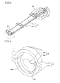
Fig. 3 is a perspective view showing atoner conveying pipe 31 constituting atoner conveying device 30 according to a first embodiment of the present disclosure, in a state where it is cut at a substantially middle portion in a longitudinal direction thereof. -
Fig. 4 is an enlarged perspective view of the vicinity of a section of thetoner conveying pipe 31 shown inFig. 3 . -
Fig. 5 is a front view of the section of thetoner conveying pipe 31 as seen from an axial direction of aconveying screw 35. -
Fig. 6 is a plan view showing thetoner conveying pipe 31 in a state where anupper pipe 31a has been demounted therefrom. -
Fig. 7 is an enlarged perspective view of the vicinity of a section of atoner conveying pipe 31 constituting atoner conveying device 30 according to a second embodiment of the present disclosure. -
Fig. 8 is a perspective view showing thetoner conveying pipe 31 used in thetoner conveying device 30 of the second embodiment, in a state where anupper pipe member 31a has been demounted therefrom. -
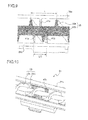
Fig. 9 is a partial sectional view of thetoner conveying pipe 31 used in thetoner conveying device 30 of the second embodiment, which is obtained by perpendicularly halving thetoner conveying pipe 31 along a longitudinal direction thereof. -
Fig. 10 is a perspective view showing atoner conveying pipe 31 used in atoner conveying device 30 according to a third embodiment of the present disclosure, in a state where anupper pipe member 31a has been demounted therefrom. -
Fig. 11 is a partial sectional view of thetoner conveying pipe 31 used in thetoner conveying device 30 of the third embodiment, which is obtained by perpendicularly halving thetoner conveying pipe 31 along a longitudinal direction thereof. - The following describes embodiments of the present disclosure with reference to the appended drawings.
Fig. 1 is a schematic sectional view showing a configuration of animage forming apparatus 1 of the present disclosure. In the image forming apparatus (e.g. a printer) 1, in performing an image forming operation, aphotosensitive drum 3 that is rotating in a clockwise direction inFig. 1 is uniformly charged by acharging unit 2. By use of a laser beam from an exposure unit (a laser scanning unit, etc.) 4 based on image data, an electrostatic latent image is formed on thephotosensitive drum 3. Then, by a developingunit 5, a developer (hereinafter, referred to as toner) is made to adhere to the electrostatic latent image to form a toner image. - Toner is supplied to the developing
unit 5 from atoner container 6. As for image data, such data is transmitted from a personal computer (not shown) or the like. Furthermore, a static eliminator (not shown) that removes residual charge on the surface of thephotosensitive drum 3 is provided on a downstream side of acleaning device 7 with respect to a rotation direction of thephotosensitive drum 3. - From a paper feed cassette 8, a sheet (a transfer sheet, an OHP sheet, etc.) is conveyed via a
sheet conveying passage 9 toward thephotosensitive drum 3 on which the toner image has been formed as described above. Through the use of aregistration roller pair 10, timing for feeding the sheet to a transfer roller 11 (image transfer portion) is adjusted. Then, by thetransfer roller 11, the toner image that has been formed on the surface of thephotosensitive drum 3 is transferred onto the sheet. The sheet onto which the toner image has been transferred is separated from thephotosensitive drum 3 and then is conveyed to afixing portion 13 having afixing roller pair 12, where the toner image is fixed. After having passed through thefixing portion 13, the sheet is conveyed to an upper portion of the apparatus via asheet conveying passage 14 to be ejected onto adischarge tray 16 by andejection roller pair 15. - Meanwhile, toner remaining on the surface of the
photosensitive drum 3 is removed by thecleaning device 7. Then, thephotosensitive drum 3 is subjected to static elimination by the static eliminator (not shown) and thereafter is charged again by thecharging unit 2. From then on, image formation is performed in a similar manner. - The
photosensitive drum 3 is formed by, for example, applying a photosensitive layer that is made of amorphous silicon (a-Si) or an organic photosensitive layer (OPC) onto an outer peripheral surface of an aluminum drum, and the surface thereof is charged by thecharging unit 2. On the surface of thephotosensitive drum 3 where a laser beam from theexposure unit 4 is received, an electrostatic latent image having attenuated charge is formed. Thecharging unit 2 charges the surface of thephotosensitive drum 3 through discharge (e.g. corona discharge). Thecharging unit 2 uses, for example, a thin wire or the like as an electrode, and applying a high voltage to the electrode causes thecharging unit 2 to perform discharge. - Based on image data, the
exposure unit 4 irradiates thephotosensitive drum 3 with a light beam (e.g. a laser beam) to form an electrostatic latent image on the surface of thephotosensitive drum 3. The developingunit 5 includes a developing roller disposed so as to be opposed to thephotosensitive drum 3. By use of the developing roller, the developingunit 5 makes a developer contained therein adhere to the electrostatic latent image on thephotosensitive drum 3 to form a toner image. - After the toner image has been transferred onto a sheet, the
cleaning device 7 removes toner (residual toner) remaining on the surface of thephotosensitive drum 3. A detailed description of thecleaning device 7 is described later. - In the fixing
portion 13, a fixingroller pair 12 composed of a heating roller that rotates in the clockwise direction inFig. 1 and a pressing roller that rotates in a counterclockwise direction inFig. 1 is housed in a housing. The heating roller includes inside thereof a halogen lamp or the like as a heat source. The sheet onto which the toner image has been transferred by thetransfer roller 11 is conveyed into the fixingportion 13 and passes through a fixing nip of the fixingroller pair 12. At this time, the sheet is heated at a predetermined temperature and pressed at a predetermined pressure, so that the toner image on the sheet is fused into a permanent image. -
Fig. 2 is a sectional view of a main part showing a configuration in the vicinity of the cleaning device 7including atoner conveying device 30 of the present disclosure. In ahousing 7a of thecleaning device 7, there are provided a rubbingroller 21 that is in line contact with thephotosensitive drum 3 in a longitudinal direction thereof under the action of a spring (not shown), acleaning blade 22, and a collectingscrew 23. - The rubbing
roller 21 is in pressure contact with thephotosensitive drum 3 under a predetermined pressure and is driven by an unshown driving section so that, at a plane of contact with thephotosensitive drum 3, it rotates (forward rotation) to the same direction as a direction to which thephotosensitive drum 3 rotates. The rubbingroller 21 is controlled to rotate at a peripheral speed faster (herein, 1.2 times faster) than that of thephotosensitive drum 3. The rubbingroller 21 is structured, for example, by forming, around a metal shaft, a foam layer of EPDM rubber having an Asker C hardness of 55° as a roller body. As a material of the roller body, without any limitation to EPDM rubber, any of other types of rubber or foamed rubber bodies may be used, and a material having an Asker C hardness in the range of 10° to 90° is favorably used. - At a position on the surface of the
photosensitive drum 3 on a downstream side in the rotation direction with respect to the plane of contact with the rubbingroller 21, thecleaning blade 22 is fixed in a state of being in contact with thephotosensitive drum 3. As thecleaning blade 22, for example, a polyurethane rubber blade having a JIS hardness of 78° is used. Thecleaning blade 22 is mounted such that, at a point of contact with thephotosensitive drum 3, it forms a predetermined angle with respect to a tangential direction of thephotosensitive drum 3. Depending on specifications of thephotosensitive drum 3, thecleaning blade 22 is set as appropriate in terms of its material, hardness, dimensions, amount of biting into thephotosensitive drum 3, force with which it is in pressure contact with thephotosensitive drum 3, and so on. - Residual toner scraped off from the surface of the
photosensitive drum 3 by the rubbingroller 21 or thecleaning blade 22 falls under gravity and is gradually accumulated in thehousing 7a. Rotation of the collectingscrew 23 causes the toner in thehousing 7a to be sequentially conveyed in a longitudinal direction (direction perpendicular to the plane ofFig. 2 ) of thehousing 7a. The residual toner that has thus been conveyed is drained to the outside of thecleaning device 7 through atoner outlet portion 25 provided at one end of a bottom surface of thehousing 7a. - The
toner conveying device 30 has a configuration including atoner conveying pipe 31 and a conveyingscrew 35. Atoner inlet port 32 and atoner outlet port 33 are formed at both ends of thetoner conveying pipe 31, respectively, andtoner inlet port 32 is connected to thetoner outlet portion 25 of thecleaning device 7, while thetoner outlet port 33 is connected to awaste toner bottle 37. The conveyingscrew 35 is composed of a conveying vane (spiral vane) 35a and arotary shaft 35b that penetrates through the center of the conveyingvane 35a and is rotatably supported inside thetoner conveying pipe 31. Therotary shaft 35b has, at one end thereof, an extended portion extending to the outside of thetoner conveying pipe 31, and adrive input gear 39 is provided at a tip end of the extended portion. Thedrive input gear 39 is connected to a drive motor (not shown) to drive the conveyingscrew 35 to rotate at a predetermined speed. The conveyingscrew 35 rotates in an arrow A direction in the figure. This causes toner conveyed from thecleaning device 7 into thetoner conveying pipe 31 via thetoner inlet port 32 to be sequentially conveyed in an arrow B direction through thetoner conveying pipe 31 to be stored in thewaste toner bottle 37 via thetoner outlet port 33. -
Fig. 3 is a perspective view showing thetoner conveying pipe 31 constituting thetoner conveying device 30 according to the first embodiment of the present disclosure, in a state where it is cut at a substantially middle portion in a longitudinal direction thereof.Fig. 4 is an enlarged perspective view of the vicinity (within a broken line circle S inFig. 3 ) of a section of thetoner conveying pipe 31.Fig. 5 is a front view of the section of thetoner conveying pipe 31 as seen from an axial direction of the conveyingscrew 35.Fig. 6 is a plan view showing thetoner conveying pipe 31 in a state where anupper pipe 31a has been demounted therefrom. Thetoner conveying pipe 31 is formed in a circular cylindrical shape by combining together theupper pipe 31a and alower pipe 31b each having a semi-arc-shaped section. - At a substantially middle portion of the
lower pipe 31b in a longitudinal direction thereof,inclined faces lower pipe 31b so as to form substantially a V-shape in section. The inclined faces 40a and 40b are formed to be symmetrical with respect to a center axis O of thetoner conveying pipe 31, and at a substantially middle portion of the conveyingscrew 35 in a longitudinal direction thereof, the conveyingvane 35a is supported at its outer peripheral edge by theinclined faces rotary shaft 35b of the conveyingscrew 35 coincides with the center axis O of thetoner conveying pipe 31. - With this configuration, the conveying screw 35rotates in a state of being supported by the
inclined faces rotary shaft 35b is substantially rectilinear. Thus, even if the conveyingscrew 35 is warped, when rotating, the conveyingscrew 35 is prevented from being deformed into a wave shape in a radial direction thereof due to an interaction between its warping and sagging under its own weight. This also makes it possible to effectively prevent occurrence of a hitting sound due to the conveyingscrew 35 impacting against an inner surface of thetoner conveying pipe 31. - Furthermore, the conveying
screw 35 rotates smoothly without the rotational load being increased, and thus generation of frictional heat attributable to rotation of the conveyingscrew 35 can be prevented. As a result, it is possible to effectively prevent a decrease in flowability and solidification of toner in thetoner conveying pipe 31. - Herein, while the conveying
screw 35 is in contact at two obliquely lower portions of the conveyingvane 35a with theinclined faces inclined faces vane 35a), a predetermined clearance C is secured between the conveyingvane 35a and the inner surface of the toner conveying pipe 31 (upper pipe 31a). The clearance C is set to have such a size as to be able to absorb dimensional tolerances and assembly tolerances of thetoner conveying pipe 31 and the conveyingscrew 35. This eliminates the possibilities that the rotational load might be increased due to the conveyingvane 35a of the conveyingscrew 35 coming in contact with the inner surface of thetoner conveying pipe 31 and that the conveyingscrew 35 might get caught between theinclined faces toner conveying pipe 31 to be kept from rotating. - Furthermore, a decrease in angle θ of each of the
inclined faces screw 35 in a horizontal direction (lateral direction inFig. 5 ). As a result, if the conveyingscrew 35 is warped, the conveyingscrew 35 might swing in the horizontal direction to impact against a side portion on the inner surface of thetoner conveying pipe 31. On the other hand, an increase in the angle θ results in the conveyingscrew 35 becoming stuck between theinclined faces screw 35 is limited to an immediately upward direction thereof, so that the rotational load is increased. For this reason, preferably, the angle θ of each of theinclined faces - While in the configuration herein described, the
inclined faces toner conveying pipe 31 in the longitudinal direction thereof, theinclined faces toner conveying pipe 31 in the longitudinal direction thereof. It is to be noted, however, that warping of the conveyingscrew 35, in most cases, occurs at a middle portion in the longitudinal direction thereof, and, therefore, an effect of supporting the conveyingscrew 35 cannot be expected so much by forming theinclined faces toner conveying pipe 31 in the longitudinal direction thereof. Sufficient effect can be expected by, as shown inFig. 6 , forming theinclined faces screw 35 in the longitudinal direction thereof, they are opposed to the conveyingscrew 35 over a length not more than one third of a total length L (L/3) of the conveyingscrew 35. -
Fig. 7 is an enlarged perspective view of the vicinity (within the broken line circle S inFig. 3 ) of a section of atoner conveying pipe 31 used in atoner conveying device 30 according to a second embodiment of the present disclosure.Fig. 8 is a perspective view showing thetoner conveying pipe 31 used in thetoner conveying device 30 of the second embodiment, in a state where anupper pipe member 31a has been demounted therefrom.Fig. 9 is a partial sectional view of thetoner conveying pipe 31 used in thetoner conveying device 30 of the second embodiment, which is obtained by perpendicularly halving thetoner conveying pipe 31 along a longitudinal direction thereof. Similarly to the first embodiment, thetoner conveying pipe 31 is formed in a circular cylindrical shape by combining together theupper pipe member 31a and alower pipe member 31b each having a semi-arc-shaped section. - A
first rib 41a andsecond ribs 41b are formed integrally with inner wall surfaces of theupper pipe member 31a and thelower pipe member 31b, respectively. Each of thefirst rib 41a and thesecond ribs 41b has a semi-arc-shaped section in a direction orthogonal to an axial direction of thetoner conveying pipe 31. Furthermore, when seen from the axial direction of thetoner conveying pipe 31, respective inner peripheral surfaces of thefirst rib 41a and thesecond ribs 41b are concentric with each other about a center axis O of thetoner conveying pipe 31, and a distance from the center axis O to each of the respective inner peripheral surfaces is set to be equal to or somewhat larger than a radius of a conveyingvane 35a of a conveyingscrew 35. - Furthermore, assuming that the conveying
vane 35a of the conveyingscrew 35 has a blade pitch L, twosecond ribs 41b are formed at a pitch of L/2. Furthermore, onefirst rib 41a is formed between thesecond ribs 41b at a position deviated from the positions of thesecond ribs 41b in the axial direction. At a substantially middle portion of the conveyingscrew 35 in a longitudinal direction thereof, the conveyingvane 35a is supported at its outer peripheral edge by thefirst rib 41a and thesecond ribs 41b. At this time, an axial center of arotary shaft 35b of the conveyingscrew 35 substantially coincides with the center axis O of thetoner conveying pipe 31. - With this configuration, if the conveying
screw 35 is warped, even when the conveyingscrew 35, as it rotates, is shifted in warping direction past an uppermost point to become about to swing in a direction (outwardly in a radial direction) in which sagging thereof under its own weight acts to increase the degree of warping thereof, the conveyingvane 35a comes in contact at its outer peripheral edge with thefirst rib 41a and thesecond ribs 41b formed on the inner wall surface of thetoner conveying pipe 31 in a rotation direction thereof. Thus, the conveyingscrew 35 is prevented from being deformed into a wave shape in the radial direction thereof due to an interaction between its warping and sagging under its own weight. Hence, the conveyingscrew 35 rotates in a state of being supported by thefirst rib 41a and thesecond ribs 41b so that therotary shaft 35b is substantially rectilinear. This also makes it possible to effectively prevent occurrence of a hitting sound due to the conveyingscrew 35 impacting against an inner surface of thetoner conveying pipe 31. - Herein, the
second ribs 41b are formed at an interval therebetween that is half the blade pitch L (L/2) of the conveyingvane 35a. Hence, regardless of how the conveyingvane 35a varies in phase as the conveyingscrew 35 rotates, the conveyingvane 35a is always in contact at part of its outer peripheral edge with either of thesecond ribs 41b. Thus, the conveyingscrew 35 is reliably supported at its lower portion by thesecond ribs 41b. The interval between thesecond ribs 41b is not limited to L/2 and may be, for example, L/3 or 3L/2. That is, as long as thesecond ribs 41b are formed at an interval therebetween that is other than one blade pitch of the conveyingvane 35a, the conveyingvane 35a is always in contact at part of its outer peripheral edge with either of thesecond ribs 41b. - Furthermore, the
first rib 41a is formed at a position (that does not coincide with the positions of thesecond ribs 41b) deviated from the positions of thesecond ribs 41b in the longitudinal direction (axial direction) of thetoner conveying pipe 31. There is, therefore, a gap between the inner wall surface of thetoner conveying pipe 31 and the conveyingvane 35a, which is continuous in the longitudinal direction of the conveyingscrew 35. This allows toner conveyed into thetoner conveying pipe 31 to move therein through this gap and thus avoids a state where the toner is blocked by thefirst rib 41a and thesecond ribs 41b. - Thus, it is also possible to prevent clogging of toner in the
toner conveying pipe 31 and a resulting increase in rotary torque of the conveyingscrew 35. Furthermore, the conveyingscrew 35 rotates smoothly without the rotational load being increased, and thus generation of frictional heat attributable to rotation of the conveyingscrew 35 can be prevented. As a result, it is possible to effectively prevent a decrease in flowability and solidification of toner in thetoner conveying pipe 31. Moreover, it is also possible to reduce a load imposed on a drive motor that drives the conveyingscrew 35 to rotate. - While in this embodiment, the
first rib 41a and thesecond ribs 41b are formed only at the substantially middle portion of thetoner conveying pipe 31 in the longitudinal direction thereof, thefirst rib 41a and thesecond ribs 41b may be formed at a predetermined interval therebetween at a plurality of locations over the entire region of the toner conveying pipe 31in the longitudinal direction thereof. It is to be noted, however, that warping of the conveyingscrew 35, in most cases, occurs at a middle portion in the longitudinal direction thereof, and, therefore, an effect of supporting the conveyingscrew 35 cannot be expected so much by forming thefirst rib 41a and thesecond ribs 41b in the vicinity of each of both end portions of thetoner conveying pipe 31 in the longitudinal direction thereof. Sufficient effect can be expected by forming thefirst rib 41a and thesecond ribs 41b so that, at the substantially middle portion of the conveyingscrew 35 in the longitudinal direction thereof, they are opposed to the conveyingscrew 35 over a length not more than one third of a total length of the conveyingscrew 35. -
Fig. 10 is a perspective view showing atoner conveying pipe 31 used in atoner conveying device 30 according to a third embodiment of the present disclosure, in a state where anupper pipe member 31a has been demounted therefrom.Fig. 11 is a partial sectional view of thetoner conveying pipe 31 used in thetoner conveying device 30 of the third embodiment, which is obtained by perpendicularly halving thetoner conveying pipe 31 along a longitudinal direction thereof. - In this embodiment, semi-arc-shaped elastic members (antivibration members) 43a and 43b are attached to inner wall surfaces of the
upper pipe member 31a and alower pipe member 31b, respectively. Theelastic members elastic members screw 35 is made) of each of theelastic members elastic members - When seen from an axial direction of the
toner conveying pipe 31, the respective inner peripheral surfaces of theelastic members toner conveying pipe 31, and a distance from the center axis O to each of the respective inner peripheral surfaces is set to be equal to or somewhat larger than a radius of a conveyingvane 35a of the conveyingscrew 35. - Furthermore, assuming that the conveying
vane 35a of the conveyingscrew 35 has a blade pitch L, each of theelastic members elastic member 43a attached to theupper pipe member 31a and theelastic member 43b attached to thelower pipe member 31b are provided at positions that do not coincide with each other in the axial direction. At a substantially middle portion of the conveyingscrew 35 in a longitudinal direction thereof, the conveyingvane 35a is supported at its outer peripheral edge by theelastic members rotary shaft 35b of the conveyingscrew 35 substantially coincides with the center axis O of thetoner conveying pipe 31. - With this configuration, if the conveying
screw 35 is warped, even when the conveyingscrew 35, as it rotates, is shifted in warping direction past an uppermost point to become about to swing in a direction (outwardly in a radial direction) in which sagging thereof under its own weight acts to increase the degree of warping thereof, the conveyingvane 35a comes in contact at its outer peripheral edge with theelastic members toner conveying pipe 31 in a rotation direction thereof. Thus, the conveyingscrew 35 is prevented from being deformed into a wave shape in the radial direction thereof due to an interaction between its warping and sagging under its own weight. Hence, the conveyingscrew 35 rotates in a state of being supported by theelastic members rotary shaft 35b is substantially rectilinear. Furthermore, thanks to the muffling effect of theelastic members screw 35 impacting against an inner surface of thetoner conveying pipe 31. - Herein, each of the
elastic members vane 35a. Hence, the conveyingvane 35a is always in contact at part of its outer peripheral edge with theelastic members screw 35 impacting against the inner wall surface of thetoner conveying pipe 31. Furthermore, the conveyingscrew 35 is reliably supported at its lower portion by theelastic member 43b. - Furthermore, the
elastic member 43a is formed at a position that does not coincide with the position of theelastic ember 43b in the longitudinal direction of thetoner conveying pipe 31. There is, therefore, a gap between the inner wall surface of thetoner conveying pipe 31 and the conveyingvane 35a, which is continuous in the longitudinal direction of the conveyingscrew 35. This allows toner conveyed into thetoner conveying pipe 31 to move therein through this gap and thus avoids a state where the toner is blocked by theelastic members - Thus, it is also possible to prevent clogging of toner in the toner conveying pipe 31and a resulting increase in rotary torque of the conveying
screw 35. Furthermore, the conveyingscrew 35 rotates smoothly without the rotational load being increased, and thus generation of frictional heat attributable to rotation of the conveyingscrew 35 can be prevented. Hence, it is possible to effectively prevent a decrease in flowability and solidification of toner in thetoner conveying pipe 31. - While in this embodiment, the elastic members 43aand 43b are provided only at a substantially middle portion of the
toner conveying pipe 31 in the longitudinal direction thereof, theelastic members toner conveying pipe 31. It is to noted, however, that warping of the conveyingscrew 35, in most cases, occurs at a middle portion in the longitudinal direction thereof, and, therefore, an effect of supporting the conveyingscrew 35 cannot be expected so much by forming theelastic members toner conveying pipe 31 in the longitudinal direction thereof. Sufficient effect can be expected by forming theelastic members screw 35 in the longitudinal direction thereof, they are opposed to the conveyingscrew 35 over a length not more than one third of a total length of the conveyingscrew 35. - The present disclosure is not limited to the foregoing embodiments and may be variously embodied within the spirit of the present disclosure. While each of the foregoing embodiments describes the
cleaning device 7 including the rubbingroller 21 and thecleaning blade 22, thetoner conveying device 30 of the present disclosure is applicable to cleaning devices of various configurations such as, for example, a configuration in which thecleaning device 7 includes only thecleaning blade 22, a configuration in which thecleaning device 7 includes a fur brush in place of thecleaning blade 22, and so on. - Furthermore, while in the foregoing first embodiment, the
inclined faces lower pipe 31b, theinclined faces lower pipe 31b and fixed to thelower pipe 31b. Moreover, theinclined faces screw 35 formed by providing the continuous spiral-shaped conveyingvane 35a around therotary shaft 35b, the shape of the conveyingvane 35a is not limited to the spiral shape. For example, as the conveyingscrew 35, a conveying screw may be used that is formed by providing, as the conveyingvane 35a, a plurality of half moon-shaped plate bodies (bodies obtained by halving circular plates) at a predetermined inclination angle in an alternate arrangement around therotary shaft 35b. - Furthermore, each of the foregoing embodiments describes an example in which the
toner conveying device 30 of the present disclosure is disposed in the waste toner collecting path from thecleaning device 7 to thewaste toner bottle 37. In addition thereto, the present disclosure is applicable in exactly the same manner also to, for example, a case where thetoner conveying device 30 is disposed in a toner conveying path from thetoner container 6 to the developingunit 5. - The present disclosure is usable for a toner conveying device having a toner conveying pipe and a conveying screw disposed inside the toner conveying pipe. By use of the present disclosure, it is possible to prevent occurrence of a hitting sound due to the conveying screw impacting against an inner surface of the toner conveying pipe and to effectively prevent a decrease in flowability and solidification of toner due to an increase in rotational load of the conveying screw.
The above embodiments of the invention as well as the appended claims and figures show multiple characterizing features of the invention in specific combinations. The skilled person will easily be able to consider further combinations or sub-combinations of these features in order to adapt the invention as defined in the claims to his specific needs.
Claims (12)
- A toner conveying device (30), comprising:a conveying screw(35) that has a rotary shaft (35b) and a conveying vane (35a) formed on an outer peripheral surface of said rotary shaft (35b);a toner conveying pipe(31) that has a circular section and inside which said conveying screw (35) is rotatably disposed; anda plurality of convex portions that are formed on an inner wall surface of the toner conveying pipe (31), and each of which is formed within an area defined by half a circumference along the inner wall surface of the toner conveying pipe (31) and supports the conveying screw (35) so that an axial center of the rotary shaft (35b) substantially coincides with a center axis of the toner conveying pipe (31).
- The toner conveying device according to claim 1, wherein
the convex portions are inclined faces (40a, 40b) that are formed at a lower portion of the inner wall surface of the toner conveying pipe (31) so as to form substantially a V-shape symmetrical with respect to the center axis of the toner conveying pipe (31). - The toner conveying device according to claim 2, wherein
each of the inclined faces (40a, 40b) forms an angle of not less than 40° and not more than 60° with respect to a horizontal plane. - The toner conveying device according to claim 2 or 3, wherein
the toner conveying pipe (31) is formed by combining together an upper pipe (31a) constituting an upper half of an outer peripheral surface of the toner conveying pipe (31) as seen from an axial direction thereof and a lower pipe (31b) constituting a lower half of the outer peripheral surface, and
the inclined faces (40a, 40b) are formed integrally with an inner wall surface of the lower pipe (31b). - The toner conveying device according to claim 1, wherein
the toner conveying pipe (31) is formed by combining together a first pipe member (31a) constituting one half of an outer peripheral surface of the toner conveying pipe (31) as seen from an axial direction thereof and a second pipe member (31b) constituting the other half of the outer peripheral surface,
the convex portions are formed on inner wall surfaces of the first pipe member (31a) and the second pipe member (31b), respectively, so that each of the convex portions has a semi-arc-shaped section, having an inner peripheral surface concentric with the inner wall surfaces about the center axis of the toner conveying pipe (31), at positions that do not coincide with each other in the axial direction of the toner conveying pipe (31), and
a distance from the center axis to the inner peripheral surface is equal to or somewhat larger than a radius of the conveying vane (35a). - The toner conveying device according to claim 5, wherein
the first pipe member (31a) and the second pipe member (31b) are an upper pipe member (31a) constituting an upper half of the toner conveying pipe (31) and a lower pipe member (31b) constituting a lower half of the toner conveying pipe (31), and
the convex portions are constituted by a first rib (41a) that is formed at at least one location on the inner wall surface of the upper pipe member (31a) and a second rib (41b) that is formed at a plurality of locations on the inner wall surface of the lower pipe member (31b). - The toner conveying device according to claim 6, wherein
the second rib (41b) is formed at an interval other than one blade pitch of the conveying vane (35a). - The toner conveying device according to claim 5, wherein
the convex portions are formed by fixing an elastic member (43a, 43b) at at least one location on the inner wall surface of the first pipe member (31a) and at at least one location on the inner wall surface of the second pipe member (31b). - The toner conveying device according to claim 8, wherein
the elastic member (43 a, 43b) is fixed to extend over a length not less than half a blade pitch of the conveying vane (35a). - The toner conveying device according to claim 8 or 9, wherein
a material having a low friction coefficient compared with that of the elastic member (43a, 43b) is applied onto an inner peripheral surface of the elastic member (43a, 43b). - The toner conveying device according to any one of claims 1 to 10, wherein
the convex portions are formed so that, at a substantially middle portion of the conveying screw (35) in a longitudinal direction thereof, they are opposed to the conveying screw (35) over a length not more than one third of a total length of the conveying screw (35). - An image forming apparatus (100) comprising the toner conveying device according to any one of claims 1 to 11.
Applications Claiming Priority (2)
| Application Number | Priority Date | Filing Date | Title |
|---|---|---|---|
| JP2012034431A JP5315428B2 (en) | 2012-02-20 | 2012-02-20 | Toner conveying apparatus and image forming apparatus having the same |
| JP2012092718A JP5678001B2 (en) | 2012-04-16 | 2012-04-16 | Toner conveying apparatus and image forming apparatus having the same |
Publications (3)
| Publication Number | Publication Date |
|---|---|
| EP2629155A2 true EP2629155A2 (en) | 2013-08-21 |
| EP2629155A3 EP2629155A3 (en) | 2016-04-06 |
| EP2629155B1 EP2629155B1 (en) | 2020-02-19 |
Family
ID=47721996
Family Applications (1)
| Application Number | Title | Priority Date | Filing Date |
|---|---|---|---|
| EP13153349.9A Active EP2629155B1 (en) | 2012-02-20 | 2013-01-30 | Toner conveying device and image forming apparatus including the same |
Country Status (3)
| Country | Link |
|---|---|
| US (1) | US8938189B2 (en) |
| EP (1) | EP2629155B1 (en) |
| CN (1) | CN103257561B (en) |
Cited By (1)
| Publication number | Priority date | Publication date | Assignee | Title |
|---|---|---|---|---|
| WO2025254532A1 (en) | 2024-06-03 | 2025-12-11 | Eagle Technology As | A feeder device with an auger pipe, pyrolysis system and method of feeding polymer particulate material |
Families Citing this family (10)
| Publication number | Priority date | Publication date | Assignee | Title |
|---|---|---|---|---|
| JP5622782B2 (en) * | 2012-04-16 | 2014-11-12 | 京セラドキュメントソリューションズ株式会社 | Toner conveying apparatus and image forming apparatus having the same |
| JP5873518B2 (en) * | 2014-03-31 | 2016-03-01 | シャープ株式会社 | Toner supply device and image forming apparatus |
| JP6427934B2 (en) * | 2014-04-18 | 2018-11-28 | 株式会社リコー | Toner conveying device and image forming apparatus |
| JP2017097054A (en) * | 2015-11-19 | 2017-06-01 | 京セラドキュメントソリューションズ株式会社 | Image forming apparatus |
| JP6497352B2 (en) * | 2016-04-27 | 2019-04-10 | 京セラドキュメントソリューションズ株式会社 | Toner conveying device and image forming apparatus |
| JP6780962B2 (en) * | 2016-06-21 | 2020-11-04 | シャープ株式会社 | Waste toner transfer unit and image forming device |
| JP2022144622A (en) * | 2021-03-19 | 2022-10-03 | 株式会社リコー | POWDER CONVEYOR AND IMAGE FORMING APPARATUS |
| CN114313832A (en) * | 2021-11-30 | 2022-04-12 | 南大光电半导体材料有限公司 | Detachable sealing device material transfer pipe |
| US12552994B2 (en) | 2022-12-02 | 2026-02-17 | Eagle Technology As | Injector, reactor, apparatus and process for pyrolysis of polymeric material |
| JP2025142474A (en) * | 2024-03-18 | 2025-10-01 | 京セラドキュメントソリューションズ株式会社 | Conveying screw and image forming apparatus |
Family Cites Families (10)
| Publication number | Priority date | Publication date | Assignee | Title |
|---|---|---|---|---|
| JPH09218627A (en) | 1996-02-08 | 1997-08-19 | Ricoh Co Ltd | Collected toner transport device |
| JP3323883B2 (en) * | 1997-10-29 | 2002-09-09 | シャープ株式会社 | Image forming device |
| JP2002132109A (en) | 2000-10-27 | 2002-05-09 | Kyocera Corp | Toner conveying device in electrophotographic apparatus |
| JP3912072B2 (en) * | 2001-10-31 | 2007-05-09 | 富士ゼロックス株式会社 | Toner transport device |
| EP1357441B1 (en) * | 2002-04-24 | 2007-03-14 | Canon Kabushiki Kaisha | Developer supply container |
| JP4088224B2 (en) | 2003-09-18 | 2008-05-21 | 佐藤ライト工業株式会社 | Toner conveying pipe and manufacturing method thereof |
| JP2006176269A (en) | 2004-12-22 | 2006-07-06 | T-Net Japan Co Ltd | Screw conveyor |
| JP5282298B2 (en) * | 2008-08-28 | 2013-09-04 | コニカミノルタ株式会社 | Image forming apparatus |
| JP5445077B2 (en) * | 2009-11-27 | 2014-03-19 | 株式会社リコー | Waste toner container and image forming apparatus |
| JP5534415B2 (en) * | 2010-02-15 | 2014-07-02 | 株式会社リコー | Developing device, process cartridge including the developing device, and image forming apparatus including the developing device or the process cartridge |
-
2013
- 2013-01-28 US US13/751,457 patent/US8938189B2/en active Active
- 2013-01-30 EP EP13153349.9A patent/EP2629155B1/en active Active
- 2013-02-20 CN CN201310054857.7A patent/CN103257561B/en active Active
Non-Patent Citations (1)
| Title |
|---|
| None |
Cited By (1)
| Publication number | Priority date | Publication date | Assignee | Title |
|---|---|---|---|---|
| WO2025254532A1 (en) | 2024-06-03 | 2025-12-11 | Eagle Technology As | A feeder device with an auger pipe, pyrolysis system and method of feeding polymer particulate material |
Also Published As
| Publication number | Publication date |
|---|---|
| US8938189B2 (en) | 2015-01-20 |
| EP2629155A3 (en) | 2016-04-06 |
| CN103257561A (en) | 2013-08-21 |
| CN103257561B (en) | 2016-06-15 |
| US20130216288A1 (en) | 2013-08-22 |
| EP2629155B1 (en) | 2020-02-19 |
Similar Documents
| Publication | Publication Date | Title |
|---|---|---|
| US8938189B2 (en) | Toner conveying device and image forming apparatus including the same | |
| JP5678001B2 (en) | Toner conveying apparatus and image forming apparatus having the same | |
| JP4990381B2 (en) | Toner discharging device, toner cartridge, and image forming apparatus | |
| EP2653934B1 (en) | Toner transportation device and image forming apparatus equipped with the same | |
| JP2020086340A (en) | Toner transport device, developing device, process cartridge, and image forming device | |
| US20100232852A1 (en) | Toner conveying mechanism, cleaning unit including the same, and image forming apparatus | |
| JP5736496B2 (en) | Toner conveying apparatus and image forming apparatus having the same | |
| CN106154796B (en) | Feeding device, process cartridge, and image forming apparatus | |
| JP2008158170A (en) | Cleaning device and image forming apparatus incorporating it | |
| CN106200300B (en) | Rotor bearing component, photo-conductor unit and image forming apparatus including the component | |
| JP6170468B2 (en) | Cleaning device and image forming apparatus | |
| JP5785899B2 (en) | Toner conveying apparatus and image forming apparatus having the same | |
| JP5998560B2 (en) | Toner recovery apparatus and image forming apparatus | |
| JP6031572B2 (en) | Toner conveying apparatus and image forming apparatus having the same | |
| JP6055886B2 (en) | Toner conveying apparatus and image forming apparatus having the same | |
| JP5820940B2 (en) | Toner conveying apparatus and image forming apparatus having the same | |
| JP5820939B2 (en) | Toner conveying apparatus and image forming apparatus having the same | |
| JP2008158168A (en) | Cleaning device and image forming apparatus having same | |
| JP2008134478A (en) | Cleaning device and image forming apparatus mounted therewith | |
| JP5315428B2 (en) | Toner conveying apparatus and image forming apparatus having the same | |
| JP6055887B2 (en) | Toner conveying apparatus and image forming apparatus having the same | |
| JP6494293B2 (en) | Cleaning device, process cartridge, image forming apparatus | |
| JP6723800B2 (en) | Conveying device, process cartridge, and image forming apparatus | |
| JP7567437B2 (en) | Toner conveying device, cleaning device, image forming device | |
| JP2019105747A (en) | Toner conveyance device and image forming apparatus including the same |
Legal Events
| Date | Code | Title | Description |
|---|---|---|---|
| PUAI | Public reference made under article 153(3) epc to a published international application that has entered the european phase |
Free format text: ORIGINAL CODE: 0009012 |
|
| AK | Designated contracting states |
Kind code of ref document: A2 Designated state(s): AL AT BE BG CH CY CZ DE DK EE ES FI FR GB GR HR HU IE IS IT LI LT LU LV MC MK MT NL NO PL PT RO RS SE SI SK SM TR |
|
| AX | Request for extension of the european patent |
Extension state: BA ME |
|
| PUAL | Search report despatched |
Free format text: ORIGINAL CODE: 0009013 |
|
| AK | Designated contracting states |
Kind code of ref document: A3 Designated state(s): AL AT BE BG CH CY CZ DE DK EE ES FI FR GB GR HR HU IE IS IT LI LT LU LV MC MK MT NL NO PL PT RO RS SE SI SK SM TR |
|
| AX | Request for extension of the european patent |
Extension state: BA ME |
|
| RIC1 | Information provided on ipc code assigned before grant |
Ipc: G03G 15/08 20060101ALI20160301BHEP Ipc: G03G 21/10 20060101AFI20160301BHEP Ipc: B65G 33/32 20060101ALI20160301BHEP |
|
| 17P | Request for examination filed |
Effective date: 20161006 |
|
| RBV | Designated contracting states (corrected) |
Designated state(s): AL AT BE BG CH CY CZ DE DK EE ES FI FR GB GR HR HU IE IS IT LI LT LU LV MC MK MT NL NO PL PT RO RS SE SI SK SM TR |
|
| STAA | Information on the status of an ep patent application or granted ep patent |
Free format text: STATUS: EXAMINATION IS IN PROGRESS |
|
| 17Q | First examination report despatched |
Effective date: 20190228 |
|
| GRAP | Despatch of communication of intention to grant a patent |
Free format text: ORIGINAL CODE: EPIDOSNIGR1 |
|
| STAA | Information on the status of an ep patent application or granted ep patent |
Free format text: STATUS: GRANT OF PATENT IS INTENDED |
|
| INTG | Intention to grant announced |
Effective date: 20190913 |
|
| GRAS | Grant fee paid |
Free format text: ORIGINAL CODE: EPIDOSNIGR3 |
|
| GRAA | (expected) grant |
Free format text: ORIGINAL CODE: 0009210 |
|
| STAA | Information on the status of an ep patent application or granted ep patent |
Free format text: STATUS: THE PATENT HAS BEEN GRANTED |
|
| AK | Designated contracting states |
Kind code of ref document: B1 Designated state(s): AL AT BE BG CH CY CZ DE DK EE ES FI FR GB GR HR HU IE IS IT LI LT LU LV MC MK MT NL NO PL PT RO RS SE SI SK SM TR |
|
| REG | Reference to a national code |
Ref country code: GB Ref legal event code: FG4D |
|
| REG | Reference to a national code |
Ref country code: CH Ref legal event code: EP |
|
| REG | Reference to a national code |
Ref country code: DE Ref legal event code: R096 Ref document number: 602013065892 Country of ref document: DE |
|
| REG | Reference to a national code |
Ref country code: AT Ref legal event code: REF Ref document number: 1235648 Country of ref document: AT Kind code of ref document: T Effective date: 20200315 |
|
| REG | Reference to a national code |
Ref country code: IE Ref legal event code: FG4D |
|
| REG | Reference to a national code |
Ref country code: NL Ref legal event code: MP Effective date: 20200219 |
|
| PG25 | Lapsed in a contracting state [announced via postgrant information from national office to epo] |
Ref country code: RS Free format text: LAPSE BECAUSE OF FAILURE TO SUBMIT A TRANSLATION OF THE DESCRIPTION OR TO PAY THE FEE WITHIN THE PRESCRIBED TIME-LIMIT Effective date: 20200219 Ref country code: NO Free format text: LAPSE BECAUSE OF FAILURE TO SUBMIT A TRANSLATION OF THE DESCRIPTION OR TO PAY THE FEE WITHIN THE PRESCRIBED TIME-LIMIT Effective date: 20200519 Ref country code: FI Free format text: LAPSE BECAUSE OF FAILURE TO SUBMIT A TRANSLATION OF THE DESCRIPTION OR TO PAY THE FEE WITHIN THE PRESCRIBED TIME-LIMIT Effective date: 20200219 |
|
| REG | Reference to a national code |
Ref country code: LT Ref legal event code: MG4D |
|
| PG25 | Lapsed in a contracting state [announced via postgrant information from national office to epo] |
Ref country code: GR Free format text: LAPSE BECAUSE OF FAILURE TO SUBMIT A TRANSLATION OF THE DESCRIPTION OR TO PAY THE FEE WITHIN THE PRESCRIBED TIME-LIMIT Effective date: 20200520 Ref country code: SE Free format text: LAPSE BECAUSE OF FAILURE TO SUBMIT A TRANSLATION OF THE DESCRIPTION OR TO PAY THE FEE WITHIN THE PRESCRIBED TIME-LIMIT Effective date: 20200219 Ref country code: LV Free format text: LAPSE BECAUSE OF FAILURE TO SUBMIT A TRANSLATION OF THE DESCRIPTION OR TO PAY THE FEE WITHIN THE PRESCRIBED TIME-LIMIT Effective date: 20200219 Ref country code: IS Free format text: LAPSE BECAUSE OF FAILURE TO SUBMIT A TRANSLATION OF THE DESCRIPTION OR TO PAY THE FEE WITHIN THE PRESCRIBED TIME-LIMIT Effective date: 20200619 Ref country code: HR Free format text: LAPSE BECAUSE OF FAILURE TO SUBMIT A TRANSLATION OF THE DESCRIPTION OR TO PAY THE FEE WITHIN THE PRESCRIBED TIME-LIMIT Effective date: 20200219 Ref country code: BG Free format text: LAPSE BECAUSE OF FAILURE TO SUBMIT A TRANSLATION OF THE DESCRIPTION OR TO PAY THE FEE WITHIN THE PRESCRIBED TIME-LIMIT Effective date: 20200519 |
|
| PG25 | Lapsed in a contracting state [announced via postgrant information from national office to epo] |
Ref country code: NL Free format text: LAPSE BECAUSE OF FAILURE TO SUBMIT A TRANSLATION OF THE DESCRIPTION OR TO PAY THE FEE WITHIN THE PRESCRIBED TIME-LIMIT Effective date: 20200219 |
|
| PG25 | Lapsed in a contracting state [announced via postgrant information from national office to epo] |
Ref country code: SM Free format text: LAPSE BECAUSE OF FAILURE TO SUBMIT A TRANSLATION OF THE DESCRIPTION OR TO PAY THE FEE WITHIN THE PRESCRIBED TIME-LIMIT Effective date: 20200219 Ref country code: EE Free format text: LAPSE BECAUSE OF FAILURE TO SUBMIT A TRANSLATION OF THE DESCRIPTION OR TO PAY THE FEE WITHIN THE PRESCRIBED TIME-LIMIT Effective date: 20200219 Ref country code: DK Free format text: LAPSE BECAUSE OF FAILURE TO SUBMIT A TRANSLATION OF THE DESCRIPTION OR TO PAY THE FEE WITHIN THE PRESCRIBED TIME-LIMIT Effective date: 20200219 Ref country code: SK Free format text: LAPSE BECAUSE OF FAILURE TO SUBMIT A TRANSLATION OF THE DESCRIPTION OR TO PAY THE FEE WITHIN THE PRESCRIBED TIME-LIMIT Effective date: 20200219 Ref country code: RO Free format text: LAPSE BECAUSE OF FAILURE TO SUBMIT A TRANSLATION OF THE DESCRIPTION OR TO PAY THE FEE WITHIN THE PRESCRIBED TIME-LIMIT Effective date: 20200219 Ref country code: PT Free format text: LAPSE BECAUSE OF FAILURE TO SUBMIT A TRANSLATION OF THE DESCRIPTION OR TO PAY THE FEE WITHIN THE PRESCRIBED TIME-LIMIT Effective date: 20200712 Ref country code: LT Free format text: LAPSE BECAUSE OF FAILURE TO SUBMIT A TRANSLATION OF THE DESCRIPTION OR TO PAY THE FEE WITHIN THE PRESCRIBED TIME-LIMIT Effective date: 20200219 Ref country code: CZ Free format text: LAPSE BECAUSE OF FAILURE TO SUBMIT A TRANSLATION OF THE DESCRIPTION OR TO PAY THE FEE WITHIN THE PRESCRIBED TIME-LIMIT Effective date: 20200219 Ref country code: ES Free format text: LAPSE BECAUSE OF FAILURE TO SUBMIT A TRANSLATION OF THE DESCRIPTION OR TO PAY THE FEE WITHIN THE PRESCRIBED TIME-LIMIT Effective date: 20200219 |
|
| REG | Reference to a national code |
Ref country code: AT Ref legal event code: MK05 Ref document number: 1235648 Country of ref document: AT Kind code of ref document: T Effective date: 20200219 |
|
| REG | Reference to a national code |
Ref country code: DE Ref legal event code: R097 Ref document number: 602013065892 Country of ref document: DE |
|
| PLBE | No opposition filed within time limit |
Free format text: ORIGINAL CODE: 0009261 |
|
| STAA | Information on the status of an ep patent application or granted ep patent |
Free format text: STATUS: NO OPPOSITION FILED WITHIN TIME LIMIT |
|
| 26N | No opposition filed |
Effective date: 20201120 |
|
| PG25 | Lapsed in a contracting state [announced via postgrant information from national office to epo] |
Ref country code: AT Free format text: LAPSE BECAUSE OF FAILURE TO SUBMIT A TRANSLATION OF THE DESCRIPTION OR TO PAY THE FEE WITHIN THE PRESCRIBED TIME-LIMIT Effective date: 20200219 Ref country code: IT Free format text: LAPSE BECAUSE OF FAILURE TO SUBMIT A TRANSLATION OF THE DESCRIPTION OR TO PAY THE FEE WITHIN THE PRESCRIBED TIME-LIMIT Effective date: 20200219 |
|
| PG25 | Lapsed in a contracting state [announced via postgrant information from national office to epo] |
Ref country code: SI Free format text: LAPSE BECAUSE OF FAILURE TO SUBMIT A TRANSLATION OF THE DESCRIPTION OR TO PAY THE FEE WITHIN THE PRESCRIBED TIME-LIMIT Effective date: 20200219 Ref country code: PL Free format text: LAPSE BECAUSE OF FAILURE TO SUBMIT A TRANSLATION OF THE DESCRIPTION OR TO PAY THE FEE WITHIN THE PRESCRIBED TIME-LIMIT Effective date: 20200219 |
|
| PG25 | Lapsed in a contracting state [announced via postgrant information from national office to epo] |
Ref country code: MC Free format text: LAPSE BECAUSE OF FAILURE TO SUBMIT A TRANSLATION OF THE DESCRIPTION OR TO PAY THE FEE WITHIN THE PRESCRIBED TIME-LIMIT Effective date: 20200219 |
|
| REG | Reference to a national code |
Ref country code: CH Ref legal event code: PL |
|
| PG25 | Lapsed in a contracting state [announced via postgrant information from national office to epo] |
Ref country code: LU Free format text: LAPSE BECAUSE OF NON-PAYMENT OF DUE FEES Effective date: 20210130 |
|
| REG | Reference to a national code |
Ref country code: BE Ref legal event code: MM Effective date: 20210131 |
|
| PG25 | Lapsed in a contracting state [announced via postgrant information from national office to epo] |
Ref country code: CH Free format text: LAPSE BECAUSE OF NON-PAYMENT OF DUE FEES Effective date: 20210131 Ref country code: LI Free format text: LAPSE BECAUSE OF NON-PAYMENT OF DUE FEES Effective date: 20210131 |
|
| PG25 | Lapsed in a contracting state [announced via postgrant information from national office to epo] |
Ref country code: IE Free format text: LAPSE BECAUSE OF NON-PAYMENT OF DUE FEES Effective date: 20210130 |
|
| PG25 | Lapsed in a contracting state [announced via postgrant information from national office to epo] |
Ref country code: BE Free format text: LAPSE BECAUSE OF NON-PAYMENT OF DUE FEES Effective date: 20210131 |
|
| PG25 | Lapsed in a contracting state [announced via postgrant information from national office to epo] |
Ref country code: HU Free format text: LAPSE BECAUSE OF FAILURE TO SUBMIT A TRANSLATION OF THE DESCRIPTION OR TO PAY THE FEE WITHIN THE PRESCRIBED TIME-LIMIT; INVALID AB INITIO Effective date: 20130130 |
|
| P01 | Opt-out of the competence of the unified patent court (upc) registered |
Effective date: 20230420 |
|
| PG25 | Lapsed in a contracting state [announced via postgrant information from national office to epo] |
Ref country code: CY Free format text: LAPSE BECAUSE OF FAILURE TO SUBMIT A TRANSLATION OF THE DESCRIPTION OR TO PAY THE FEE WITHIN THE PRESCRIBED TIME-LIMIT Effective date: 20200219 |
|
| PG25 | Lapsed in a contracting state [announced via postgrant information from national office to epo] |
Ref country code: MK Free format text: LAPSE BECAUSE OF FAILURE TO SUBMIT A TRANSLATION OF THE DESCRIPTION OR TO PAY THE FEE WITHIN THE PRESCRIBED TIME-LIMIT Effective date: 20200219 |
|
| PG25 | Lapsed in a contracting state [announced via postgrant information from national office to epo] |
Ref country code: MT Free format text: LAPSE BECAUSE OF FAILURE TO SUBMIT A TRANSLATION OF THE DESCRIPTION OR TO PAY THE FEE WITHIN THE PRESCRIBED TIME-LIMIT Effective date: 20200219 |
|
| PG25 | Lapsed in a contracting state [announced via postgrant information from national office to epo] |
Ref country code: TR Free format text: LAPSE BECAUSE OF FAILURE TO SUBMIT A TRANSLATION OF THE DESCRIPTION OR TO PAY THE FEE WITHIN THE PRESCRIBED TIME-LIMIT Effective date: 20200219 |
|
| PGFP | Annual fee paid to national office [announced via postgrant information from national office to epo] |
Ref country code: GB Payment date: 20251220 Year of fee payment: 14 |
|
| PGFP | Annual fee paid to national office [announced via postgrant information from national office to epo] |
Ref country code: FR Payment date: 20251217 Year of fee payment: 14 |
|
| PGFP | Annual fee paid to national office [announced via postgrant information from national office to epo] |
Ref country code: DE Payment date: 20251217 Year of fee payment: 14 |