EP2628888A1 - Electromechanical actuator of a rotational drive for a load with a torque limiter - Google Patents
Electromechanical actuator of a rotational drive for a load with a torque limiter Download PDFInfo
- Publication number
- EP2628888A1 EP2628888A1 EP13155746.4A EP13155746A EP2628888A1 EP 2628888 A1 EP2628888 A1 EP 2628888A1 EP 13155746 A EP13155746 A EP 13155746A EP 2628888 A1 EP2628888 A1 EP 2628888A1
- Authority
- EP
- European Patent Office
- Prior art keywords
- torque
- actuator according
- motor
- friction
- torque limiter
- Prior art date
- Legal status (The legal status is an assumption and is not a legal conclusion. Google has not performed a legal analysis and makes no representation as to the accuracy of the status listed.)
- Granted
Links
- 230000007246 mechanism Effects 0.000 claims abstract description 35
- 230000002457 bidirectional effect Effects 0.000 claims abstract description 18
- 230000008878 coupling Effects 0.000 claims abstract description 17
- 238000010168 coupling process Methods 0.000 claims abstract description 17
- 238000005859 coupling reaction Methods 0.000 claims abstract description 17
- 230000005540 biological transmission Effects 0.000 claims description 19
- 239000003638 chemical reducing agent Substances 0.000 claims description 11
- 239000003302 ferromagnetic material Substances 0.000 claims description 4
- 238000005096 rolling process Methods 0.000 claims description 3
- 230000000903 blocking effect Effects 0.000 description 7
- 238000013024 troubleshooting Methods 0.000 description 6
- 238000011084 recovery Methods 0.000 description 5
- 230000000694 effects Effects 0.000 description 3
- 230000005291 magnetic effect Effects 0.000 description 3
- 230000008439 repair process Effects 0.000 description 3
- 241001417494 Sciaenidae Species 0.000 description 2
- 239000011449 brick Substances 0.000 description 2
- 210000000056 organ Anatomy 0.000 description 2
- 230000004434 saccadic eye movement Effects 0.000 description 2
- 238000004804 winding Methods 0.000 description 2
- 230000015556 catabolic process Effects 0.000 description 1
- 238000006731 degradation reaction Methods 0.000 description 1
- 238000006073 displacement reaction Methods 0.000 description 1
- 230000004907 flux Effects 0.000 description 1
- 230000010354 integration Effects 0.000 description 1
- 230000004048 modification Effects 0.000 description 1
- 238000012986 modification Methods 0.000 description 1
- 238000005457 optimization Methods 0.000 description 1
Images


Classifications
-
- E—FIXED CONSTRUCTIONS
- E06—DOORS, WINDOWS, SHUTTERS, OR ROLLER BLINDS IN GENERAL; LADDERS
- E06B—FIXED OR MOVABLE CLOSURES FOR OPENINGS IN BUILDINGS, VEHICLES, FENCES OR LIKE ENCLOSURES IN GENERAL, e.g. DOORS, WINDOWS, BLINDS, GATES
- E06B9/00—Screening or protective devices for wall or similar openings, with or without operating or securing mechanisms; Closures of similar construction
- E06B9/56—Operating, guiding or securing devices or arrangements for roll-type closures; Spring drums; Tape drums; Counterweighting arrangements therefor
- E06B9/68—Operating devices or mechanisms, e.g. with electric drive
- E06B9/74—Operating devices or mechanisms, e.g. with electric drive adapted for selective electrical or manual operation
Definitions
- the invention relates to an electromechanical actuator driving a load around a geometric axis of rotation. It relates more particularly to a mechanism of the above type, for driving the load motorized and manually, especially in case of failure of the engine or its power supply. It relates in particular to a mechanism of the previous type, for the driving of a roller shutter. It also relates to certain technological bricks used in such an electromechanical drive actuator. It relates in particular to a torque transmission mechanism whose function is to transmit any driving torque from a first rotating member to a second rotating member, but to block the second rotating member in the absence of engine torque applied by the first rotating member, whatever the direction of rotation. It also relates to a mechanism combining an engine and a torque limiter.
- an electromechanical actuator for axially rotating a shutter comprising an electric motor for driving the shutter through a main drive shaft, and a troubleshooting operation comprising a torque transmission mechanism provided manually via a crank, to drive the shutter in case of failure or failure of the power supply of the electric motor.
- the torque transmission mechanism comprises a bidirectional freewheel for transmitting to an intermediate shaft any motor torque exerted by the crank on a secondary drive member and for securing the intermediate shaft to the fixed frame in the absence of a driving torque exerted by the secondary tree.
- bidirectional free wheel any mechanism for transmitting from a driving shaft - here the secondary drive shaft - to a driven shaft - here the intermediate shaft - a driving torque exerted by the drive shaft, regardless of the direction of rotation of the two shafts, and prohibits the transmission of torque and energy from the driven shaft to the drive shaft.
- the motor directly drives the motor shaft which is uncoupled from the intermediate shaft and the secondary drive shaft, by displacement of a first brake plate.
- the brake couples the motor shaft to a fixed frame. If the roller shutter exerts on the drive shaft a torque, for example due to the weight of an already deployed portion of the flap, the motor shaft remains stationary, because of its kinematic connection to the frame via the mechanism to bidirectional free wheel.
- the two-way freewheel couples the secondary drive shaft to the shaft secondary drive, so that the torque exerted by the user is transmitted to a second brake plate, and the housing of the actuator which then rotates on itself to drive the shutter.
- the link to the frame of the bidirectional freewheel mechanism is also not explained. Its implementation is complex because of the rotation of the actuator housing when using a repair maneuver.
- the use of a bidirectional freewheel mechanism incorporating a brake spring creates complex design constraints and is not necessarily suitable in heavy load driving cases, such as commercial grids.
- the invention aims to overcome the disadvantages of the state of the art and to propose, in a small footprint, a reliable mechanism that allows the drive by a motor or by a secondary power source, in practice produced manually by a user .
- the torque limiter is calibrated to fully transmit any torque less than or equal to a reference limit torque, and not to transmit torque greater than the reference limit torque.
- the reference limit torque is preferably greater than the maximum engine torque of the electric motor and preferably less than the maximum torque allowed by the drive train. transmission between the motor and the load, in other words the breaking torque of the most fragile element of the transmission kinematic chain.
- the torque limiter has friction surfaces pressed against each other with a predetermined force.
- the friction surfaces are preferably frustoconical for optimization of the axial and radial dimensions, but other shapes can also be envisaged.
- the frustoconical friction surfaces are particularly suitable since it allows, for a given engine power, to accommodate the torque limiter in the internal diameter of the motor stator.
- one of the friction surfaces is integral with the intermediate driven member which can be made in a single piece or in several interconnected parts, forming a compact assembly.
- the torque limiter and the bidirectional coupling have a multifunctional common member, which results in a gain in compactness.
- the torque limiter comprises at least one elastic return member exerting the predetermined force.
- the actuator comprises a disengagement control for uncoupling the torque limiter when the motor is powered.
- This clutch acts preferentially on one of the parts of the torque limiter.
- the torque limiter thus also fulfills a clutch or brake function, in order to, in certain operating modes, interrupt the transmission kinematic chain between the main motor shaft and the secondary drive member. This multiplicity of functions in the same organ is particularly advantageous for the compactness of the whole.
- the clutch control comprises a yoke of ferromagnetic material activated by a field induced by the motor and movable between a coupling position and a disengagement position.
- the movement of the cylinder head may in particular be a translation movement parallel to the main drive shaft.
- the breech is in this case the only moving part in translation, the other parts, and in particular the secondary drive member, the intermediate driven member and the main drive shaft being in axial rotational movement.
- these rotations are around a single geometric reference axis of the mechanism.
- the mechanism thus has a high degree of integration in a small radial and axial space.
- the elastic return member referred to above reminds the cylinder head to the coupling position.
- the cylinder head is provided with one of the friction surfaces.
- the invention is particularly suitable for driving shutters or commercial grilles.
- a rotary drum driven by the drive shaft and having a cylindrical outer surface for winding a shutter or a grid constituting the load.
- the mechanism further comprises a secondary drive member rotating the secondary drive member.
- a secondary drive member rotating the secondary drive member.
- the secondary drive member is shaped to allow a user to manually drive the secondary drive member. This may include a crank with a bevel gear, or a belt and pulley device.
- the actuator comprises at least one sliding or rolling bearing ensuring the connection between the intermediate driven member and the main drive shaft, for guiding the friction cone relative to the shaft when a pair is exerted on the crank and the free rotation of the shaft during operation of the engine.
- the bearing preferably comprises an outer ring integral with the intermediate driven member, an inner ring secured to the main drive shaft and, if appropriate, rolling bodies arranged between the rings.
- the main drive shaft can drive the load either directly or via a speed reducer.
- the speed reducer and the torque limiter are preferably located on either side of the engine.
- the torque limiter is then calibrated to transmit fully any torque less than or equal to a reference limit torque, and not to transmit torque greater than the reference limit torque, the reference limit torque being greater than the maximum motor torque of the electric motor. and less than the maximum permissible torque of the gearbox.
- the first friction member is a multifunctional member for controlling the coupling or uncoupling of the torque limiter according to the presence or absence of power to the motor.
- the torque limiter is uncoupled when the engine is powered, and coupled when the engine is not powered.
- the torque limiter can function as a brake if the second friction member is fixed or coupled to a fixed frame. It may also be, according to a preferred embodiment, coupled to a troubleshooting crank or other troubleshooting driver, possibly via a bidirectional coupling, for example a two-way freewheel coupling.
- the predetermined force is preferably such that the torque limiter transmits integrally any torque less than or equal to a reference limit torque, and is not capable of transmitting torque greater than the reference limit torque.
- the reference limit torque is preferably greater than the maximum engine torque of the electric motor. This arrangement is particularly useful when the second friction member is coupled to a troubleshooting drive member, the maximum torque must be controlled, including a manually driven crank.
- the reference limit torque is lower than the maximum torque allowed by the transmission kinematic chain between the motor and the load, in other words the breaking torque of the most fragile element of the drive train. of transmission.
- the first and second friction surfaces are frustoconical.
- This arrangement makes it possible to limit the outside diameter of the friction surfaces and the elastic restoring force of the return member, for a given reference limit torque, while preserving a very great simplicity for the device. It also influences the dimensioning of the motor itself, since it is the magnetic flux of the motor which must generate the force opposing the elastic return member. It is therefore possible, with frustoconical friction surfaces, and at equal power of the motor, to accommodate the torque limiter in the internal diameter of the stator of the motor.
- the second friction member is secured to a rotary receiving member, in a first position, to secure the second friction member to a fixed frame, and in a second position to secure the second member of friction to a secondary drive shaft.
- the actuator comprises a speed reducer, the speed reducer and the torque limiter being preferably located on either side of the engine.
- the torque limiter is preferably calibrated to transmit fully any torque less than or equal to a reference limit torque, and not to transmit torque greater than the reference limit torque, the reference limit torque being greater than the maximum engine torque of the electric motor. and less than the maximum permissible input torque of the gearbox.
- the first friction member consists of a part, which reduces the number of parts and simplify assembly.
- the torque transmission mechanism constitutes a bidirectional coupling in the sense that it operates in both directions of rotation, the function of which is to transmit any engine torque from the first member rotating towards the second rotating member, but to prevent any transmission of torque. motor from the second member rotating towards the first rotating member, blocking in this case the rotation of the second rotating member.
- the equi-part arrangement of the locking elements ensures a good distribution of the contact points ensuring the transmission of torque between the first rotating member and the second rotating member, or between the second rotating member and the fixed drum. This balanced distribution limits the stresses perpendicular to the reference axis. It makes it possible to limit in particular the wear of the rotating guide bearings of the first rotating member and / or the second rotating member.
- This mechanism can be implemented as a technological brick in different locations of a transmission kinematic chain, and in particular between a secondary drive shaft and a primary drive shaft, where appropriate with the interposition of a torque limiter as indicated below. the previous aspect of the invention.
- the locking elements are rollers, preferably cylindrical rollers.
- the pairs of blocking elements are three or more.
- the number of three is preferred insofar as it constitutes an ideal compromise between the desire for a balanced distribution of the blocking elements and the resulting bulk.
- the mechanism further comprises resilient return members of each locking member to the locking position, which can be constituted by leaf springs.
- each spring blade cooperates with two locking elements associated with two opposite directions of rotation. It is thus possible to ensure the elastic return of the locking elements with a reduced number of parts, in this case as many springs as pairs of locking elements.
- each spring blade cooperates with two locking elements by separating them from one another. Both blocking elements may belong to two adjacent pairs. This arrangement is particularly advantageous from the point of view of space.
- the first rotating member forms a star comprising a pair of pair of locking elements, each branch being preferably disposed between the two locking elements of a pair of locking element, and being movable between a middle position without contact with the locking elements, a driving position in a direction of rotation in contact with one of the locking elements and a driving position in the opposite direction of rotation in contact with the other element blocking.
- the second rotating member is provided with a friction surface
- the mechanism further comprising a third member rotating about the reference geometric axis and having a friction surface disposed facing the friction surface.
- the third rotating member being movable in translation by relative to the second member rotating between a coupling position in which the friction surface of the third rotating member is in contact with the friction surface of the second rotating member, and a disengagement position in which the friction surface of the third rotating member is away from the second rotating member.
- the third rotating member can advantageously be returned to the contact position by a return spring.
- the mechanism may further comprise a counter-torque member, in particular a friction element, in particular a friction seal, in particular an O-ring, for exerting a predetermined pair of friction between the second rotating member and the fixed drum.
- a counter-torque member in particular a friction element, in particular a friction seal, in particular an O-ring, for exerting a predetermined pair of friction between the second rotating member and the fixed drum.
- FIG. 1 is schematically illustrated a motorized actuator 10 housed in a cylindrical fixed housing 12 which may for example be disposed at the end or inserted inside a winding tube of a curtain or shutter or other load .
- the mechanism 10 comprises an electric motor 14 composed of a stator 16 and a rotor 18 forming a main drive shaft 20, a speed reducer 22 connected to the main drive shaft 18 and having an output shaft 23 designed to drive a load, and a recovery device 24 to allow driving of the motor shaft 20 in case of failure of the motor 14 or its power supply.
- the recovery device 24 and the speed reducer 22 are located on either side of the motor 14 at both ends of the shaft 20.
- the troubleshooting device 24 consists of a secondary drive member 26, here a crank handle, a bevel gear 28 for transmitting the rotation of the crank handle to a secondary drive shaft of troubleshooting 30, d a bi-directional freewheel 32 and a torque limiter 34.
- the motor shaft 20 and the secondary drive shaft 30 rotate around a same reference geometric axis 100 of the mechanism.
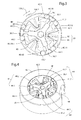
- the bidirectional free wheel 32 illustrated on the Figures 2 to 4 , has an input member 36 integral with the recovery shaft 30 and forming therewith a secondary drive member 38, a multifunctional intermediate driven member 40 consisting of a receiving member 40.1 and a friction cone 40.2 secured to each other, a fixed drum 42 consisting of a drum having a cylindrical wall 42.1 rotated radially inwardly and a guide shoulder 42.2.
- the fixed drum 42 has been intentionally omitted to allow the spring blades 48 and the receiving part 40.1 to be seen.
- the free wheel also comprises three pairs 44 of cylindrical rollers 44.1, 44.2 housed in housings 46 delimited by a wall 40.11 or 40.12 of the receiving part 40.1 forming a ramp and the cylindrical wall 42.1 of the fixed drum 42.
- the rollers are pressed against these walls by springs 48.
- Each pair of rollers 44 comprises a roller 44.1 cooperating with a wall 40.11 of the receiving part and associated with a direction of rotation 100.1 around the geometric axis 100, and a roller 44.2 cooperating with a wall 40.12 of the receiving part and associated with the opposite direction of rotation 100.2.
- each spring 48 is constituted by a blade having in the plane of the figure 3 a general shape of W with curved ends to each accommodate a roller 44.1 or 44.2 and push in a position of contact with the walls 40.11 or 40.12 of the receiving part 40.1 and the wall 42.1 of the fixed drum.
- the receiving part 40.1 has been deliberately omitted to allow the spring blades 48 to be viewed.
- the input member 36 and the intermediate driven member 40 can rotate around the reference geometrical axis 100 in the direction 100.1 and the meaning 100.2.
- the input member 36 has a general star shape with as many branches 36.1 as pairs of rollers 44, here three.
- Each branch 36.1 enters a housing 46 between the two rollers 44.1, 44.2 of a pair to cooperate alternately with one or the other.
- the bidirectional free wheel 32 is completed by a friction seal 50 disposed in a groove 40.13 of the receiving part 40.1 and coming into contact with the cylindrical wall 42.1 of the fixed drum 42.
- the friction cone 40.2 is provided with frustoconical friction linings 52 and is an integral part of the torque limiter 34, which further comprises a yoke 54 forming a frustoconical bowl with a friction surface 56 facing that of the friction cone 40.2 .
- the yoke 54 is made of a low hysteresis ferromagnetic material, and is connected to the main drive shaft 20 by a key 58 which allows sliding in translation parallel to the reference geometric axis 100 of the yoke 54 relative to the shaft. 20 but prohibits any rotation between these two parts.
- the yoke 54 and the friction cone 40.2 respectively form a first friction member and a second friction member of the torque limiter 34. It is also shown on FIG. figure 5 a ball bearing 62 disposed between the friction cone 40.2 and the shaft 20, guiding the friction cone relative to the shaft 20 when a torque is exerted on the crank and the free rotation of the shaft 20 during operation of the engine.
- the mechanism works as follows.
- the bi-directional freewheel 32 is in the middle position shown in FIG. figure 3 : the branches 36.1 are without contact with the rollers 44.1, 44.2, halfway between the rollers 44.1, 44.2, which are wedged between the wall 42.1 of the fixed drum 42 and the wall 40.11 or 40.12 of the receiving part 40.1, solidarising these two pieces by jamming.
- a motor torque applied in a direction 100.1 or in the other 100.2 to the friction cone 40.2 is integrally transmitted to the fixed drum 42, without causing rotation of the intermediate driven member 40 or the secondary drive member 38 due to jamming rollers between the wall 42.1 of the fixed drum 42 and the wall 40.11 or 40.12 of the receiving part 40.1. No engine torque can therefore be transmitted from the friction cone 40.2 to the secondary drive member 38.
- the torque limiter 34 and the free wheel 32 then have a brake function, preventing any inadvertent rotation of the driven motor shaft 20. by the charge.
- the friction o-ring 50 constitutes a counter-torque member which introduces a slight torque of friction to limit or avoid a saccade effect when the load is not constant. This is the case for example when the load is constituted by a slatted shutter or a large grid that takes place.
- the yoke 54 moves axially under the effect of the magnetic field induced in the direction 100.4 and is pressed against the motor by binding the spring 60, canceling the air gap and releasing the limiter of torque 34.
- the rotor 18 is then free to rotate and drive the speed reducer 22 and the load.
- the spring 60 appears partially inserted in the rotor 18. It could alternatively be contained in the volume of the cylinder head 54.
- the cylinder head 54 As soon as the power supply of the motor 14 is cut off, for example because the load has reached the desired position, the cylinder head 54, repelled by the spring 60, moves and comes back against the friction cone 40.2. The latter can not rotate due to the median positioning of the bidirectional free wheel, so that the rotor 18 is also immobilized, ensuring the positioning of the load.
- the frustoconical shape of the friction surfaces 52, 56 of the torque limiter is particularly suitable for limiting the diameter of the torque limiter in the inner diameter of the stator 16 and the cylinder 12 without oversizing the spring 60, so the motor.
- other forms may where appropriate be adopted, providing a plateau torque limiter or multi-disk.
- the friction surfaces may be directly formed on the friction cone and the cylinder head, or consist of inserts.
- the bidirectional freewheel 32 may have any suitable structure, with rollers, balls, ratchets, or cams for example. It can consist of two stages of freewheeling in series.
- the same mechanism can be used with a secondary engine instead of the crank.
Landscapes
- Engineering & Computer Science (AREA)
- Structural Engineering (AREA)
- Architecture (AREA)
- Civil Engineering (AREA)
- One-Way And Automatic Clutches, And Combinations Of Different Clutches (AREA)
- Transmission Devices (AREA)
- Connection Of Motors, Electrical Generators, Mechanical Devices, And The Like (AREA)
- Operating, Guiding And Securing Of Roll- Type Closing Members (AREA)
Abstract
Description
L'invention se rapporte à un actionneur électromécanique d'entraînement d'une charge autour d'un axe géométrique de rotation. Elle se rapporte plus particulièrement à un mécanisme du type précédent, permettant d'entraîner la charge de façon motorisée et de façon manuelle, notamment en cas de défaillance du moteur ou de son alimentation. Elle se rapporte notamment à un mécanisme du type précédent, destiné à l'entraînement d'un volet roulant. Elle se rapporte également à certaines briques technologiques utilisées dans un tel actionneur électromécanique d'entraînement. Elle se rapporte en particulier à un mécanisme de transmission de couple ayant pour fonction de transmettre tout couple moteur d'un premier organe tournant à un deuxième organe tournant, mais de bloquer le deuxième organe tournant en l'absence de couple moteur appliqué par le premier organe tournant, ceci quel que soit le sens de rotation. Elle se rapporte également à un mécanisme combinant un moteur et un limiteur de couple.The invention relates to an electromechanical actuator driving a load around a geometric axis of rotation. It relates more particularly to a mechanism of the above type, for driving the load motorized and manually, especially in case of failure of the engine or its power supply. It relates in particular to a mechanism of the previous type, for the driving of a roller shutter. It also relates to certain technological bricks used in such an electromechanical drive actuator. It relates in particular to a torque transmission mechanism whose function is to transmit any driving torque from a first rotating member to a second rotating member, but to block the second rotating member in the absence of engine torque applied by the first rotating member, whatever the direction of rotation. It also relates to a mechanism combining an engine and a torque limiter.
Dans le document
Le mécanisme de transmission de couple comporte une roue libre bidirectionnelle pour transmettre à un arbre intermédiaire tout couple moteur exercé par la manivelle sur un organe menant secondaire et pour solidariser l'arbre intermédiaire au bâti fixe en l'absence de couple moteur exercé par l'arbre menant secondaire. On entend ici par roue libre bidirectionnel tout mécanisme permettant de transmettre d'un arbre menant - ici l'arbre menant secondaire - à un arbre mené - ici l'arbre intermédiaire - un couple moteur exercé par l'arbre menant, quel que soit le sens de rotation des deux arbres, et qui interdise la transmission de couple et d'énergie de l'arbre mené à l'arbre menant.The torque transmission mechanism comprises a bidirectional freewheel for transmitting to an intermediate shaft any motor torque exerted by the crank on a secondary drive member and for securing the intermediate shaft to the fixed frame in the absence of a driving torque exerted by the secondary tree. Here we mean by bidirectional free wheel any mechanism for transmitting from a driving shaft - here the secondary drive shaft - to a driven shaft - here the intermediate shaft - a driving torque exerted by the drive shaft, regardless of the direction of rotation of the two shafts, and prohibits the transmission of torque and energy from the driven shaft to the drive shaft.
En fonctionnement normal, le moteur entraîne directement l'arbre moteur qui est désaccouplé de l'arbre intermédiaire et de l'arbre menant secondaire, par déplacement d'un premier plateau de frein. En cas de défaut d'alimentation ou de défaillance du moteur, le frein accouple l'arbre moteur à un bâti fixe. Si le volet roulant exerce sur l'arbre moteur un couple, par exemple du fait du poids d'une partie déjà déployée du volet, l'arbre moteur reste immobile, du fait de sa liaison cinématique au bâti par l'intermédiaire du mécanisme à roue libre bidirectionnelle. Si toutefois l'utilisateur actionne la manivelle dans un sens ou dans l'autre et exerce un couple sur l'arbre menant secondaire dans un sens de rotation ou l'autre, la roue libre bidirectionnelle accouple l'arbre menant secondaire à l'arbre menant secondaire, de sorte que le couple exercé par l'utilisateur est transmis à un deuxième plateau de frein, et au carter de l'actionneur qui tourne alors sur lui-même pour entraîner le volet.In normal operation, the motor directly drives the motor shaft which is uncoupled from the intermediate shaft and the secondary drive shaft, by displacement of a first brake plate. In case of power failure or motor failure, the brake couples the motor shaft to a fixed frame. If the roller shutter exerts on the drive shaft a torque, for example due to the weight of an already deployed portion of the flap, the motor shaft remains stationary, because of its kinematic connection to the frame via the mechanism to bidirectional free wheel. If, however, the user actuates the crank in either direction and exerts a torque on the secondary drive shaft in either direction of rotation, the two-way freewheel couples the secondary drive shaft to the shaft secondary drive, so that the torque exerted by the user is transmitted to a second brake plate, and the housing of the actuator which then rotates on itself to drive the shutter.
Il s'avère qu'un tel mécanisme pose un certain nombre de contraintes, notamment liées à l'alimentation en énergie électrique du moteur, du fait de la rotation du carter de l'actionneur lors de l'utilisation d'une manoeuvre de dépannage. De plus, à l'usage, il n'est pas exempt de risque de dégradation en utilisation manuelle. En effet, le couple généré manuellement par l'utilisateur, amplifié par l'étage réducteur, et transmis intégralement par le mécanisme de transmission de couple, peut excéder le couple maximal admissible et, en cas de coincement du volet roulant, provoquer la casse de la pièce la plus fragile de la chaîne cinématique de transmission, notamment de l'étage réducteur.It turns out that such a mechanism poses a number of constraints, particularly related to the power supply of the engine, due to the rotation of the actuator housing when using a repair maneuver . In addition, in use, it is not free of risk of degradation in manual use. Indeed, the torque generated manually by the user, amplified by the reducing stage, and transmitted integrally by the torque transmission mechanism, may exceed the maximum permissible torque and, in case of jamming of the shutter, cause breakage of the most fragile part of the transmission kinematic chain, especially of the reducing stage.
Par ailleurs, le lien au bâti du mécanisme à roue libre bidirectionnelle n'est par ailleurs pas explicité. Sa mise en oeuvre s'avère complexe du fait de la rotation du carter de l'actionneur lors de l'utilisation d'une manoeuvre de dépannage. De plus, l'utilisation d'un mécanisme à roue libre bidirectionnelle intégrant un ressort-frein crée des contraintes de dimensionnement complexes et n'est pas nécessairement adapté dans des cas d'entraînement de charges importantes, telles que des grilles commerciales.Furthermore, the link to the frame of the bidirectional freewheel mechanism is also not explained. Its implementation is complex because of the rotation of the actuator housing when using a repair maneuver. In addition, the use of a bidirectional freewheel mechanism incorporating a brake spring creates complex design constraints and is not necessarily suitable in heavy load driving cases, such as commercial grids.
L'invention vise à remédier aux inconvénients de l'état de la technique et à proposer, dans un encombrement réduit, un mécanisme fiable qui permette l'entraînement par un moteur ou par une source de puissance secondaire, en pratique produite manuellement par un utilisateur.The invention aims to overcome the disadvantages of the state of the art and to propose, in a small footprint, a reliable mechanism that allows the drive by a motor or by a secondary power source, in practice produced manually by a user .
Pour ce faire est proposé, selon un premier aspect de l'invention, un actionneur électromécanique d'entraînement en rotation d'une charge comportant :
- un moteur électrique pour entraîner la charge par l'intermédiaire d'un arbre moteur principal,
- un organe menant secondaire,
- un mécanisme de transmission de couple relié à l'organe menant secondaire et à un organe rotatif mené intermédiaire, comportant un bâti fixe et un accouplement bidirectionnel pour transmettre à l'organe mené intermédiaire tout couple moteur exercé par l'organe menant secondaire et pour solidariser l'organe mené intermédiaire au bâti fixe en l'absence de couple moteur exercé par l'arbre menant secondaire, et
- un limiteur de couple reliant l'organe mené intermédiaire à l'arbre moteur principal.
- an electric motor for driving the load through a main drive shaft,
- a secondary driving organ,
- a torque transmission mechanism connected to the secondary drive member and to an intermediate driven rotary member, comprising a fixed frame and a bidirectional coupling for transmitting to the intermediate driven member any driving torque exerted by the secondary drive member and to secure the intermediate driven member fixed frame in the absence of engine torque exerted by the secondary drive shaft, and
- a torque limiter connecting the intermediate driven member to the main drive shaft.
Le limiteur de couple est taré pour transmettre intégralement tout couple inférieur ou égal à un couple limite de référence, et pour ne pas transmettre de couple supérieur au couple limite de référence. En choisissant judicieusement le couple limite de référence, on peut ainsi protéger la charge ou la partie de mécanisme la plus fragile. En pratique, le couple limite de référence est de préférence supérieur au couple moteur maximal du moteur électrique et de préférence inférieur au couple maximal admissible par la chaîne cinématique de transmission entre le moteur et la charge, en d'autres termes le couple de rupture de l'élément le plus fragile de la chaîne cinématique de transmission.The torque limiter is calibrated to fully transmit any torque less than or equal to a reference limit torque, and not to transmit torque greater than the reference limit torque. By judiciously choosing the reference limit torque, it is thus possible to protect the load or the most fragile part of the mechanism. In practice, the reference limit torque is preferably greater than the maximum engine torque of the electric motor and preferably less than the maximum torque allowed by the drive train. transmission between the motor and the load, in other words the breaking torque of the most fragile element of the transmission kinematic chain.
Selon un mode de réalisation, le limiteur de couple comporte des surfaces de friction pressées l'une contre l'autre avec une force prédéterminée. Les surfaces de friction sont de préférence tronconiques pour une optimisation de l'encombrement axial et radial, mais d'autres formes peuvent également être envisagées. Les surfaces de friction tronconiques s'avèrent particulièrement adapté puisqu'il permet, pour une puissance du moteur donnée, de loger le limiteur de couple dans le diamètre interne du stator du moteur.In one embodiment, the torque limiter has friction surfaces pressed against each other with a predetermined force. The friction surfaces are preferably frustoconical for optimization of the axial and radial dimensions, but other shapes can also be envisaged. The frustoconical friction surfaces are particularly suitable since it allows, for a given engine power, to accommodate the torque limiter in the internal diameter of the motor stator.
Selon un mode de réalisation, l'une des surfaces de friction est solidaire de l'organe mené intermédiaire qui peut être réalisé en une pièce monobloc ou en plusieurs pièces solidarisées, formant un ensemble compact. Ainsi le limiteur de couple et l'accouplement bidirectionnel ont un organe commun multifonctionnel, ce qui se traduit par un gain de compacité.According to one embodiment, one of the friction surfaces is integral with the intermediate driven member which can be made in a single piece or in several interconnected parts, forming a compact assembly. Thus the torque limiter and the bidirectional coupling have a multifunctional common member, which results in a gain in compactness.
Selon un mode de réalisation, le limiteur de couple comporte au moins un organe de rappel élastique exerçant la force prédéterminée.According to one embodiment, the torque limiter comprises at least one elastic return member exerting the predetermined force.
De préférence, l'actionneur comporte une commande de débrayage pour désaccoupler le limiteur de couple lorsque le moteur est alimenté. Ce débrayage agit préférentiellement sur une des pièces du limiteur de couple. Le limiteur de couple remplit ainsi également une fonction d'embrayage ou de frein, pour, dans certains modes de fonctionnement, interrompre la chaîne cinématique de transmission entre l'arbre moteur principal et l'organe menant secondaire. Cette multiplicité des fonctions dans un même organe se révèle particulièrement avantageuse pour la compacité de l'ensemble.Preferably, the actuator comprises a disengagement control for uncoupling the torque limiter when the motor is powered. This clutch acts preferentially on one of the parts of the torque limiter. The torque limiter thus also fulfills a clutch or brake function, in order to, in certain operating modes, interrupt the transmission kinematic chain between the main motor shaft and the secondary drive member. This multiplicity of functions in the same organ is particularly advantageous for the compactness of the whole.
Selon un mode de réalisation, la commande de débrayage comporte une culasse en matériau ferromagnétique activée par un champ induit par le moteur et mobile entre une position d'accouplement et une position de désaccouplement. Le mouvement de la culasse peut notamment être un mouvement de translation parallèle à l'arbre moteur principal. Il est à noter que la culasse est dans ce cas la seule pièce mobile en translation, les autres pièces, et notamment l'organe menant secondaire, l'organe mené intermédiaire et l'arbre moteur principal étant en mouvement de rotation axiale. De préférence, ces rotations se font autour d'un seul et même axe géométrique de référence du mécanisme. Le mécanisme présente de ce fait un haut degré d'intégration dans un faible encombrement radial et axial.According to one embodiment, the clutch control comprises a yoke of ferromagnetic material activated by a field induced by the motor and movable between a coupling position and a disengagement position. The movement of the cylinder head may in particular be a translation movement parallel to the main drive shaft. It should be noted that the breech is in this case the only moving part in translation, the other parts, and in particular the secondary drive member, the intermediate driven member and the main drive shaft being in axial rotational movement. Preferably, these rotations are around a single geometric reference axis of the mechanism. The mechanism thus has a high degree of integration in a small radial and axial space.
Préférentiellement, l'organe de rappel élastique dont il a été question plus haut rappelle la culasse vers la position d'accouplement.Preferably, the elastic return member referred to above reminds the cylinder head to the coupling position.
Pour une nouvelle fois limiter le nombre de pièces, on peut prévoir que la culasse soit pourvue d'une des surfaces de friction.Again to limit the number of parts, it can be provided that the cylinder head is provided with one of the friction surfaces.
Comme évoqué ci-dessus, l'invention est particulièrement adaptée à l'entraînement de volets roulants ou de grilles commerciales. On peut notamment prévoir un tambour rotatif entraîné par l'arbre moteur et présentant une surface extérieure cylindrique pour enrouler un volet roulant ou une grille constituant la charge.As mentioned above, the invention is particularly suitable for driving shutters or commercial grilles. In particular, it is possible to provide a rotary drum driven by the drive shaft and having a cylindrical outer surface for winding a shutter or a grid constituting the load.
Selon un mode de réalisation, le mécanisme comporte en outre un organe d'entraînement secondaire entraînant en rotation l'organe menant secondaire. Il peut par exemple s'agir d'un moteur secondaire. Toutefois, selon un mode de réalisation préféré, l'organe d'entraînement secondaire est conformé de manière à permettre à un utilisateur d'entraîner manuellement l'organe menant secondaire. Il peut s'agir notamment d'une manivelle à renvoi d'angle, ou d'un dispositif à courroie et poulie.According to one embodiment, the mechanism further comprises a secondary drive member rotating the secondary drive member. It may for example be a secondary engine. However, according to a preferred embodiment, the secondary drive member is shaped to allow a user to manually drive the secondary drive member. This may include a crank with a bevel gear, or a belt and pulley device.
Selon un mode de réalisation, l'actionneur comprend au moins un palier lisse ou à roulement assurant la liaison entre l'organe mené intermédiaire et l'arbre moteur principal, pour guider le cône de friction par rapport à l'arbre lorsqu'un couple est exercé sur la manivelle et la libre rotation de l'arbre lors d'un fonctionnement du moteur. Le palier comporte de préférence une bague extérieure solidaire de l'organe mené intermédiaire, une bague intérieure solidaire de l'arbre moteur principal et le cas échéant des corps roulants disposés entre la bagues.According to one embodiment, the actuator comprises at least one sliding or rolling bearing ensuring the connection between the intermediate driven member and the main drive shaft, for guiding the friction cone relative to the shaft when a pair is exerted on the crank and the free rotation of the shaft during operation of the engine. The bearing preferably comprises an outer ring integral with the intermediate driven member, an inner ring secured to the main drive shaft and, if appropriate, rolling bodies arranged between the rings.
Il est à noter que l'arbre moteur principal peut entraîner la charge soit directement, soit par l'intermédiaire d'un réducteur de vitesse. Le réducteur de vitesse et le limiteur de couple sont de préférence situés de part et d'autre du moteur. Le limiteur de couple est alors taré pour transmettre intégralement tout couple inférieur ou égal à un couple limite de référence, et pour ne pas transmettre de couple supérieur au couple limite de référence, le couple limite de référence étant supérieur au couple moteur maximal du moteur électrique et inférieur au couple maximal admissible du réducteur de vitesse.It should be noted that the main drive shaft can drive the load either directly or via a speed reducer. The speed reducer and the torque limiter are preferably located on either side of the engine. The torque limiter is then calibrated to transmit fully any torque less than or equal to a reference limit torque, and not to transmit torque greater than the reference limit torque, the reference limit torque being greater than the maximum motor torque of the electric motor. and less than the maximum permissible torque of the gearbox.
Selon un autre aspect de l'invention, celle-ci a trait à un actionneur électromécanique d'entraînement en rotation d'une charge comportant :
- un moteur électrique comportant un stator et un rotor pour entraîner un arbre moteur définissant un axe géométrique de référence,
- un limiteur de couple comportant :
- un premier organe de friction mobile en translation parallèlement à l'axe géométrique de référence entre une position d'accouplement et une position de désaccouplement et solidaire en rotation de l'arbre moteur, le premier organe de friction comportant une première surface de friction, le premier organe de friction comportant en outre une culasse en matériau ferromagnétique disposée à distance d'entrefer variable du rotor du moteur électrique, le moteur électrique sous tension générant un champ magnétique attirant le premier organe de friction vers la position de désaccouplement en contact avec le rotor
- un deuxième organe de friction comportant une deuxième surface de friction en regard de la première surface de friction, et
- un organe de rappel élastique pour rappeler le premier organe de friction vers la position d'accouplement et appliquer la première surface de friction contre la deuxième surface de friction une force prédéterminée en position d'accouplement.
- an electric motor having a stator and a rotor for driving a motor shaft defining a reference geometric axis,
- a torque limiter comprising:
- a first friction member movable in translation parallel to the reference geometric axis between a coupling position and a disengagement position and integral in rotation with the drive shaft, the first friction member having a first friction surface, the first friction member further comprising a yoke of ferromagnetic material disposed at a distance from the variable gap of the rotor of the electric motor, the energized electric motor generating a magnetic field attracting the first friction member to the uncoupling position in contact with the rotor
- a second friction member having a second friction surface facing the first friction surface, and
- an elastic return member for biasing the first friction member towards the coupling position and applying the first friction surface against the second friction surface a predetermined force in the coupling position.
Le premier organe de friction constitue un organe multifonctionnel permettant de commander l'accouplement ou le désaccouplement du limiteur de couple en fonction de la présence ou de l'absence d'alimentation électrique du moteur. Le limiteur de couple est désaccouplé lorsque le moteur est alimenté, et accouplé lorsque le moteur n'est pas alimenté. Le limiteur de couple peut fonctionner comme un frein si le deuxième organe de friction est fixe ou accouplé à un bâti fixe. Il peut également être, suivant un mode préféré de réalisation, attelé à une manivelle de dépannage ou un autre organe d'entraînement de dépannage, le cas échéant par l'intermédiaire d'un accouplement bidirectionnel, par exemple un accouplement à roue libre bidirectionnelle.The first friction member is a multifunctional member for controlling the coupling or uncoupling of the torque limiter according to the presence or absence of power to the motor. The torque limiter is uncoupled when the engine is powered, and coupled when the engine is not powered. The torque limiter can function as a brake if the second friction member is fixed or coupled to a fixed frame. It may also be, according to a preferred embodiment, coupled to a troubleshooting crank or other troubleshooting driver, possibly via a bidirectional coupling, for example a two-way freewheel coupling.
En position d'accouplement, la force prédéterminée est préférentiellement telle que le limiteur de couple transmet intégralement tout couple inférieur ou égal à un couple limite de référence, et n'est pas apte à transmettre de couple supérieur au couple limite de référence. Le couple limite de référence est de préférence supérieur au couple moteur maximal du moteur électrique. Cette disposition est particulièrement utile lorsque le deuxième organe de friction est attelé à un organe d'entraînement de dépannage, dont le couple maximal doit être contrôlé, notamment une manivelle entraînée à la main. Selon un mode de réalisation, le couple limite de référence est inférieur au couple maximal admissible par la chaîne cinématique de transmission entre le moteur et la charge, en d'autres termes le couple de rupture de l'élément le plus fragile de la chaîne cinématique de transmission.In the coupling position, the predetermined force is preferably such that the torque limiter transmits integrally any torque less than or equal to a reference limit torque, and is not capable of transmitting torque greater than the reference limit torque. The reference limit torque is preferably greater than the maximum engine torque of the electric motor. This arrangement is particularly useful when the second friction member is coupled to a troubleshooting drive member, the maximum torque must be controlled, including a manually driven crank. According to one embodiment, the reference limit torque is lower than the maximum torque allowed by the transmission kinematic chain between the motor and the load, in other words the breaking torque of the most fragile element of the drive train. of transmission.
Suivant un mode de réalisation préféré, les première et deuxième surfaces de friction sont tronconiques. Cette disposition permet de limiter le diamètre extérieur des surfaces de friction et la force de rappel élastique de l'organe de rappel, pour un couple limite de référence donné, tout en préservant une très grande simplicité au dispositif. Elle influe également sur le dimensionnement du moteur lui-même, puisque c'est le flux magnétique du moteur qui doit générer la force s'opposant à l'organe de rappel élastique. On peut donc, avec des surfaces de friction tronconiques, et à puissance égale du moteur, loger le limiteur de couple dans le diamètre interne du stator du moteur.In a preferred embodiment, the first and second friction surfaces are frustoconical. This arrangement makes it possible to limit the outside diameter of the friction surfaces and the elastic restoring force of the return member, for a given reference limit torque, while preserving a very great simplicity for the device. It also influences the dimensioning of the motor itself, since it is the magnetic flux of the motor which must generate the force opposing the elastic return member. It is therefore possible, with frustoconical friction surfaces, and at equal power of the motor, to accommodate the torque limiter in the internal diameter of the stator of the motor.
Suivant un mode de réalisation préféré, le deuxième organe de friction est solidarisé à un organe de réception rotatif permettant, dans une première position, de solidariser le deuxième organe de friction à un bâti fixe, et dans une deuxième position de solidariser le deuxième organe de friction à un arbre menant secondaire.According to a preferred embodiment, the second friction member is secured to a rotary receiving member, in a first position, to secure the second friction member to a fixed frame, and in a second position to secure the second member of friction to a secondary drive shaft.
Suivant un mode de réalisation, l'actionneur comporte un réducteur de vitesse, le réducteur de vitesse et le limiteur de couple étant de préférence situés de part et d'autre du moteur. Le limiteur de couple est préférentiellement taré pour transmettre intégralement tout couple inférieur ou égal à un couple limite de référence, et pour ne pas transmettre de couple supérieur au couple limite de référence, le couple limite de référence étant supérieur au couple moteur maximal du moteur électrique et inférieur au couple d'entrée maximal admissible du réducteur de vitesse.According to one embodiment, the actuator comprises a speed reducer, the speed reducer and the torque limiter being preferably located on either side of the engine. The torque limiter is preferably calibrated to transmit fully any torque less than or equal to a reference limit torque, and not to transmit torque greater than the reference limit torque, the reference limit torque being greater than the maximum engine torque of the electric motor. and less than the maximum permissible input torque of the gearbox.
Suivant un mode de réalisation particulièrement avantageux, le premier organe de friction est constitué d'une pièce, ce qui permet de réduire le nombre de pièces et de simplifier l'assemblage.According to a particularly advantageous embodiment, the first friction member consists of a part, which reduces the number of parts and simplify assembly.
Suivant un autre aspect de l'invention, celle-ci a trait à un mécanisme de transmission de couple comportant :
- un premier organe tournant autour d'un axe géométrique de référence,
- un deuxième organe tournant autour de l'axe géométrique de référence,
- un tambour fixe présentant une face cylindrique intérieure, et
- une pluralité de paires d'éléments de blocage, chaque élément de blocage étant associé à un sens de rotation autour de l'axe géométrique de référence et apte à prendre une position de blocage au contact du deuxième organe tournant et de la face cylindrique intérieure du tambour fixe pour empêcher toute rotation du deuxième organe tournant dans le sens de rotation associé, et une position d'entrainement au contact du premier organe tournant et du deuxième organe tournant pour transmettre au deuxième organe tournant un couple moteur exercé par le premier organe tournant dans le sens de rotation associé, chaque paire d'éléments de blocage comportant un élément de blocage associé à un premier sens de rotation et un deuxième élément de blocage associé au sens de rotation opposé, les paires étant angulairement équiréparties autour de l'axe de référence.
- a first member rotating around a reference geometric axis,
- a second member rotating around the reference geometric axis,
- a fixed drum having an inner cylindrical face, and
- a plurality of pairs of locking elements, each locking element being associated with a direction of rotation about the axis geometric reference and adapted to take a locking position in contact with the second rotating member and the inner cylindrical face of the fixed drum to prevent rotation of the second member rotating in the associated rotational direction, and a driving position in contact with the first rotating member and the second rotating member for transmitting to the second rotating member a driving torque exerted by the first member rotating in the associated rotational direction, each pair of locking elements comprising a locking member associated with a first direction of rotation and a second blocking element associated with the opposite direction of rotation, the pairs being angularly equidistributed around the reference axis.
Le mécanisme de transmission de couple constitue un accouplement bidirectionnel au sens où il fonctionne dans les deux sens de rotation, dont la fonction est de transmettre tout couple moteur depuis le premier organe tournant vers le deuxième organe tournant, mais d'empêcher toute transmission de couple moteur depuis le deuxième organe tournant vers le premier organe tournant, en bloquant dans ce cas la rotation du deuxième organe tournant.The torque transmission mechanism constitutes a bidirectional coupling in the sense that it operates in both directions of rotation, the function of which is to transmit any engine torque from the first member rotating towards the second rotating member, but to prevent any transmission of torque. motor from the second member rotating towards the first rotating member, blocking in this case the rotation of the second rotating member.
La disposition équirépartie des éléments de blocage assure une bonne répartition des points de contact assurant la transmission du couple entre le premier organe tournant et le deuxième organe tournant, ou entre le deuxième organe tournant et le tambour fixe. Cette répartition équilibrée permet de limiter les sollicitations perpendiculaires à l'axe de référence. Elle permet de limiter notamment l'usure des paliers de guidage en rotation du premier organe tournant et/ou du deuxième organe tournant.The equi-part arrangement of the locking elements ensures a good distribution of the contact points ensuring the transmission of torque between the first rotating member and the second rotating member, or between the second rotating member and the fixed drum. This balanced distribution limits the stresses perpendicular to the reference axis. It makes it possible to limit in particular the wear of the rotating guide bearings of the first rotating member and / or the second rotating member.
Ce mécanisme peut être mis en oeuvre en tant que brique technologique dans différents emplacements d'une chaîne cinématique de transmission, et notamment entre un arbre menant secondaire et un arbre menant primaire, le cas échéant avec interposition d'un limiteur de couple comme indiqué suivant l'aspect précédent de l'invention.This mechanism can be implemented as a technological brick in different locations of a transmission kinematic chain, and in particular between a secondary drive shaft and a primary drive shaft, where appropriate with the interposition of a torque limiter as indicated below. the previous aspect of the invention.
Selon un mode de réalisation, les éléments de blocage sont des galets, de préférence des rouleaux cylindriques.According to one embodiment, the locking elements are rollers, preferably cylindrical rollers.
Suivant un mode de réalisation préféré, les paires d'éléments de blocage sont au nombre de trois ou plus. Le nombre de trois est préféré dans la mesure où il constitue un compromis idéal entre le souhait d'une répartition équilibrée des éléments de blocage et l'encombrement résultant.According to a preferred embodiment, the pairs of blocking elements are three or more. The number of three is preferred insofar as it constitutes an ideal compromise between the desire for a balanced distribution of the blocking elements and the resulting bulk.
Le mécanisme comporte en outre des organes de rappel élastique de chaque élément de blocage vers la position de blocage, qui peuvent être constitués par des lames ressorts. Suivant un mode de réalisation, chaque lame ressort coopère avec deux éléments de blocage associés à deux sens de rotation opposés. On peut ainsi assurer le rappel élastique des éléments de blocage avec un nombre réduit de pièces, en l'occurrence autant de ressorts que de paires d'éléments de blocage. Préférentiellement, chaque lame de ressort coopère avec deux éléments de blocage en les écartant l'un de l'autre. Les deux éléments de blocage peuvent appartenir à deux paires adjacentes. Cette disposition s'avère particulièrement avantageuse du point de vue de l'encombrement.The mechanism further comprises resilient return members of each locking member to the locking position, which can be constituted by leaf springs. According to one embodiment, each spring blade cooperates with two locking elements associated with two opposite directions of rotation. It is thus possible to ensure the elastic return of the locking elements with a reduced number of parts, in this case as many springs as pairs of locking elements. Preferably, each spring blade cooperates with two locking elements by separating them from one another. Both blocking elements may belong to two adjacent pairs. This arrangement is particularly advantageous from the point of view of space.
Suivant un mode de réalisation, le premier organe tournant forme une étoile comportant une branche par paire d'éléments de blocage, chaque branche étant disposée de préférence entre les deux éléments de blocage d'une paire d'élément de blocage, et étant mobile entre une position médiane sans contact avec les éléments de blocage, une position d'entraînement dans un sens de rotation en contact avec l'un des éléments de blocage et une position d'entraînement dans le sens de rotation opposé en contact avec l'autre élément de blocage. Cette disposition permet de minimiser le nombre de pièce tout en assurant la symétrie recherchée.According to one embodiment, the first rotating member forms a star comprising a pair of pair of locking elements, each branch being preferably disposed between the two locking elements of a pair of locking element, and being movable between a middle position without contact with the locking elements, a driving position in a direction of rotation in contact with one of the locking elements and a driving position in the opposite direction of rotation in contact with the other element blocking. This arrangement makes it possible to minimize the number of pieces while ensuring the desired symmetry.
Suivant un mode de réalisation, le deuxième organe tournant est pourvu d'une surface de friction, le mécanisme comportant en outre un troisième organe tournant autour de l'axe géométrique de référence et comportant une surface de friction disposée en regard de la surface de friction du deuxième organe tournant, le troisième organe tournant étant mobile en translation par rapport au deuxième organe tournant entre une position d'accouplement dans laquelle la surface de friction du troisième organe tournant est en contact avec la surface de friction du deuxième organe tournant, et une position de désaccouplement dans laquelle la surface de friction du troisième organe tournant est à distance du deuxième organe tournant. Le troisième organe tournant peut avantageusement être rappelé vers la position de contact par un ressort de rappel.According to one embodiment, the second rotating member is provided with a friction surface, the mechanism further comprising a third member rotating about the reference geometric axis and having a friction surface disposed facing the friction surface. of the second rotating member, the third rotating member being movable in translation by relative to the second member rotating between a coupling position in which the friction surface of the third rotating member is in contact with the friction surface of the second rotating member, and a disengagement position in which the friction surface of the third rotating member is away from the second rotating member. The third rotating member can advantageously be returned to the contact position by a return spring.
Le mécanisme peut en outre comporter un organe de contre-couple, notamment un élément de frottement, notamment un joint de frottement, notamment un joint torique, pour exercer un couple prédéterminé de frottement entre le deuxième organe tournant et le tambour fixe. Ce couple de frottement, de faible amplitude, permet de limiter ou d'éliminer certains effets de saccade provoqués par une charge qui ne génère pas un couple résistant constant, par exemple un rideau à lames ou une grille de grande dimension qui se déroule irrégulièrement. En pratique l'amplitude du frottement généré par l'élément de frottement est inférieure à 10% du couple limite de référence.The mechanism may further comprise a counter-torque member, in particular a friction element, in particular a friction seal, in particular an O-ring, for exerting a predetermined pair of friction between the second rotating member and the fixed drum. This friction torque, of low amplitude, makes it possible to limit or eliminate certain saccade effects caused by a load that does not generate a constant resistive torque, for example a curtain with blades or a large grid which unfolds irregularly. In practice the amplitude of the friction generated by the friction element is less than 10% of the reference limit torque.
D'autres caractéristiques et avantages de l'invention ressortiront à la lecture de la description qui suit, en référence aux figures annexées, qui illustrent :
- la
figure 1 , une vue schématique d'un mécanisme selon l'invention, - la
figure 2 , une vue éclatée d'une roue libre bidirectionnelle du mécanisme de lafigure 1 ; - la
figure 3 , une vue en coupe de la roue libre bidirectionnelle de lafigure 2 , dans une position de roue libre ; - la
figure 4 , une vue en perspective de la roue libre bidirectionnelle de lafigure 2 ; - la
figure 5 , une vue de détail en coupe du mécanisme de lafigure 1 ; - la
figure 6 une vue éclaté de certains éléments du mécanisme de lafigure 1 .
- the
figure 1 , a schematic view of a mechanism according to the invention, - the
figure 2 , an exploded view of a bidirectional freewheel mechanism of thefigure 1 ; - the
figure 3 , a sectional view of the bidirectional free wheel of thefigure 2 in a freewheel position; - the
figure 4 , a perspective view of the bidirectional freewheel of thefigure 2 ; - the
figure 5 , a detail view in section of the mechanism of thefigure 1 ; - the
figure 6 an exploded view of some elements of the mechanism of thefigure 1 .
Sur la
Le dispositif de dépannage 24 est constitué d'un organe d'entraînement secondaire 26, ici une manivelle de dépannage, d'un renvoi d'angle 28 pour transmettre la rotation de la manivelle de dépannage à un arbre menant secondaire de dépannage 30, d'une roue libre bidirectionnelle 32 et d'un limiteur de couple 34. L'arbre moteur 20 et l'arbre menant secondaire 30 tournent autour d'un même axe géométrique de référence 100 du mécanisme.The
La roue libre bidirectionnelle 32, illustrée sur les
Comme illustré sur les
Le mécanisme fonctionne de la manière suivante.The mechanism works as follows.
En l'absence d'alimentation du moteur, comme illustré sur la
Si aucun couple n'est exercé sur la manivelle de dépannage 26, la roue libre bidirectionnelle 32 est dans la position médiane représentée sur la
Si, à partir de la position médiane de la
Si le couple exercé par l'utilisateur sur la manivelle de dépannage 26 est trop élevé et dépasse le couple maximal admissible par le limiteur de couple 34, les surfaces de friction 52, 56 se mettent à glisser l'une par rapport à l'autre, ne transmettant que partiellement le couple. En choisissant judicieusement la tension du ressort 60, on peut ainsi protéger la partie du mécanisme la plus fragile, en l'occurrence le réducteur de vitesse 22. Un tel dépassement de couple admissible pourrait subvenir à l'arrivée du volet en fin de course, sur une butée ou du fait de la présence d'un obstacle ou d'un point dur dans la coulisse.If the torque exerted by the user on the repair crank 26 is too high and exceeds the maximum torque allowed by the
Dès que le couple moteur exercé sur la manivelle de dépannage 26 cesse, les lames de ressort 48 ramènent les galets 44.1 et 44.2 dans la position de blocage, bloquant l'arbre moteur 20.As soon as the driving torque exerted on the recovery crank 26 ceases, the
Lorsque le moteur 14 est mis sous tension, la culasse 54 se déplace axialement sous l'effet du champ magnétique induit dans le sens 100.4 et vient s'accoler contre le moteur en bandant le ressort 60, annulant l'entrefer et libérant le limiteur de couple 34. Le rotor 18 est alors libre de tourner et d'entraîner le réducteur de vitesse 22 et la charge. Sur la
Dès que l'alimentation électrique du moteur 14 est coupée, par exemple parce que la charge a atteint la position souhaitée, la culasse 54, repoussée par le ressort 60, se déplace et vient s'accoler de nouveau contre le cône de friction 40.2. Ce dernier ne peut tourner du fait du positionnement médian de la roue libre bidirectionnelle, de sorte que le rotor 18 se trouve également immobilisé, garantissant le positionnement de la charge.As soon as the power supply of the
Naturellement, diverses modifications sont possibles. La forme tronconique des surfaces de friction 52, 56 du limiteur de couple s'avère particulièrement adaptée pour limiter le diamètre du limiteur de couple dans le diamètre intérieur du stator 16 et du cylindre 12 sans surdimensionner le ressort 60, donc le moteur. Toutefois, d'autres formes peuvent le cas échéant être adoptées, en prévoyant un limiteur de couple à plateau, voire multidisque. Les surfaces de friction peuvent être directement formées sur le cône de friction et la culasse, ou être constituées par des garnitures rapportées. La roue libre bidirectionnelle 32 peut avoir toute structure adaptée, à galets, billes, cliquets, ou cames par exemple. Elle peut être constituée de deux étages de roue libre en série.Naturally, various modifications are possible. The frustoconical shape of the friction surfaces 52, 56 of the torque limiter is particularly suitable for limiting the diameter of the torque limiter in the inner diameter of the
Le même mécanisme peut être utilisé avec un moteur secondaire à la place de la manivelle.The same mechanism can be used with a secondary engine instead of the crank.
Claims (15)
caractérisé en ce qu'il comporte un limiteur de couple (34) reliant l'organe mené intermédiaire (40) à l'arbre moteur principal (20).
characterized in that it comprises a torque limiter (34) connecting the intermediate driven member (40) to the main drive shaft (20).
Priority Applications (1)
| Application Number | Priority Date | Filing Date | Title |
|---|---|---|---|
| PL13155746T PL2628888T3 (en) | 2012-02-20 | 2013-02-19 | Electromechanical actuator of a rotational drive for a load with a torque limiter |
Applications Claiming Priority (1)
| Application Number | Priority Date | Filing Date | Title |
|---|---|---|---|
| FR1251517A FR2987067B1 (en) | 2012-02-20 | 2012-02-20 | ELECTROMECHANICAL ACTUATOR FOR DRIVING INTO ROTATION OF A TORQUE LIMITING LOAD |
Publications (2)
| Publication Number | Publication Date |
|---|---|
| EP2628888A1 true EP2628888A1 (en) | 2013-08-21 |
| EP2628888B1 EP2628888B1 (en) | 2014-09-24 |
Family
ID=47710055
Family Applications (1)
| Application Number | Title | Priority Date | Filing Date |
|---|---|---|---|
| EP13155746.4A Active EP2628888B1 (en) | 2012-02-20 | 2013-02-19 | Electromechanical actuator of a rotational drive for a load with a torque limiter |
Country Status (5)
| Country | Link |
|---|---|
| EP (1) | EP2628888B1 (en) |
| JP (1) | JP3183230U (en) |
| CN (1) | CN203548661U (en) |
| FR (1) | FR2987067B1 (en) |
| PL (1) | PL2628888T3 (en) |
Cited By (1)
| Publication number | Priority date | Publication date | Assignee | Title |
|---|---|---|---|---|
| EP3663501A1 (en) * | 2018-12-03 | 2020-06-10 | D&M Kg | Coiling shaft assembly for a building opening shading device |
Families Citing this family (1)
| Publication number | Priority date | Publication date | Assignee | Title |
|---|---|---|---|---|
| KR101846703B1 (en) | 2016-09-12 | 2018-04-06 | 현대자동차주식회사 | Drive motor capable of separating rotating member when the rotating member is restrained |
Citations (3)
| Publication number | Priority date | Publication date | Assignee | Title |
|---|---|---|---|---|
| DE3420789A1 (en) * | 1984-06-04 | 1985-12-05 | Josef 7312 Kirchheim Pradler | Drive unit |
| DE3504489A1 (en) | 1985-02-09 | 1986-08-14 | Lothar 7984 Wolpertswende Huber | Device for manual operation of the winding shaft, which can be driven by an electric motor, for example of a roller shutter in the case of the electric motor being unpowered |
| EP0751278A1 (en) * | 1995-06-28 | 1997-01-02 | Bubendorff S.A. | Motorized roller shutter |
-
2012
- 2012-02-20 FR FR1251517A patent/FR2987067B1/en not_active Expired - Fee Related
-
2013
- 2013-02-19 JP JP2013000874U patent/JP3183230U/en not_active Expired - Fee Related
- 2013-02-19 PL PL13155746T patent/PL2628888T3/en unknown
- 2013-02-19 EP EP13155746.4A patent/EP2628888B1/en active Active
- 2013-02-20 CN CN201320078121.9U patent/CN203548661U/en not_active Expired - Lifetime
Patent Citations (3)
| Publication number | Priority date | Publication date | Assignee | Title |
|---|---|---|---|---|
| DE3420789A1 (en) * | 1984-06-04 | 1985-12-05 | Josef 7312 Kirchheim Pradler | Drive unit |
| DE3504489A1 (en) | 1985-02-09 | 1986-08-14 | Lothar 7984 Wolpertswende Huber | Device for manual operation of the winding shaft, which can be driven by an electric motor, for example of a roller shutter in the case of the electric motor being unpowered |
| EP0751278A1 (en) * | 1995-06-28 | 1997-01-02 | Bubendorff S.A. | Motorized roller shutter |
Cited By (1)
| Publication number | Priority date | Publication date | Assignee | Title |
|---|---|---|---|---|
| EP3663501A1 (en) * | 2018-12-03 | 2020-06-10 | D&M Kg | Coiling shaft assembly for a building opening shading device |
Also Published As
| Publication number | Publication date |
|---|---|
| CN203548661U (en) | 2014-04-16 |
| PL2628888T3 (en) | 2015-03-31 |
| FR2987067A1 (en) | 2013-08-23 |
| JP3183230U (en) | 2013-05-09 |
| EP2628888B1 (en) | 2014-09-24 |
| FR2987067B1 (en) | 2014-03-28 |
Similar Documents
| Publication | Publication Date | Title |
|---|---|---|
| EP2925606B1 (en) | Wheel motorizing system, notably for an aircraft wheel | |
| EP2543591B1 (en) | System for electric motorisation of a wheel | |
| CA2825054C (en) | Device for braking and rotating an aircraft wheel | |
| FR2563203A1 (en) | WINCH | |
| FR2952689A1 (en) | LIMIT SLIDE DIFFERENTIAL WITH DYNAMIC PUSH DEVICE | |
| FR2940674A1 (en) | ROTARY TYPE POWER GAIN MACHINE | |
| WO2016005134A2 (en) | Electromechanical actautor comprising a mechanical roller torque limiter | |
| FR3003306A1 (en) | THERMAL ENGINE STARTER | |
| EP0957293B1 (en) | Electromagnetic screw-nut actuator | |
| EP2628888B1 (en) | Electromechanical actuator of a rotational drive for a load with a torque limiter | |
| WO2014106714A1 (en) | Gearbox for a self-propelled device such as a lawnmower | |
| FR2940773A1 (en) | Transmission device for self-propelled rolling machine i.e. mowing tractor, has output semi-shafts braked by controlled braking device assembled on forward gear/reverse gear intermediate shaft | |
| EP2745879A2 (en) | Automatically engageable and disengageable transmission device | |
| EP3048043B1 (en) | Method for rotating an aircraft wheel | |
| EP1509705B1 (en) | Actuator with two motors, a differential reducer and a torque limiter | |
| FR2987090A1 (en) | Torque transmitting mechanism for electromechanical actuator for rotating e.g. curtain, has rotary elements around reference axis, and fixed drum including rollers, where rollers are angularly and uniformly distributed around reference axis | |
| EP1783394B1 (en) | Safety device for a mechanical transmission by means of a blocking gearing | |
| EP2816253B1 (en) | Epicyclic gear for winding and unwinding actuator | |
| EP2765322B1 (en) | Aircraft cabin seat comprising an actuator | |
| FR2956888A1 (en) | Grip brake for slowing down mobile body e.g. rotary disk, has clutch arranged between motor and speed-reducer or between speed-reducer and rod for disconnecting motor from reducer during braking or for disconnecting reducer from rod | |
| WO2016005135A2 (en) | Elecromechanical actuator comprising a dual-function braking device | |
| EP3994061A1 (en) | Aircraft seat | |
| FR3059752A1 (en) | AGREEMENT MEANS AUTOBLOQUING A CONTINUOUSLY VARIABLE TRANSMISSION SYSTEM | |
| FR3136266A3 (en) | One-way clutch device and method | |
| FR3132692A1 (en) | CLUTCH WITH MULTIPLE DEACTIVATION CONTROLS FOR STEERING-BY-WIRE SYSTEM |
Legal Events
| Date | Code | Title | Description |
|---|---|---|---|
| PUAI | Public reference made under article 153(3) epc to a published international application that has entered the european phase |
Free format text: ORIGINAL CODE: 0009012 |
|
| AK | Designated contracting states |
Kind code of ref document: A1 Designated state(s): AL AT BE BG CH CY CZ DE DK EE ES FI FR GB GR HR HU IE IS IT LI LT LU LV MC MK MT NL NO PL PT RO RS SE SI SK SM TR |
|
| AX | Request for extension of the european patent |
Extension state: BA ME |
|
| 17P | Request for examination filed |
Effective date: 20140221 |
|
| RBV | Designated contracting states (corrected) |
Designated state(s): AL AT BE BG CH CY CZ DE DK EE ES FI FR GB GR HR HU IE IS IT LI LT LU LV MC MK MT NL NO PL PT RO RS SE SI SK SM TR |
|
| GRAP | Despatch of communication of intention to grant a patent |
Free format text: ORIGINAL CODE: EPIDOSNIGR1 |
|
| INTG | Intention to grant announced |
Effective date: 20140411 |
|
| GRAS | Grant fee paid |
Free format text: ORIGINAL CODE: EPIDOSNIGR3 |
|
| GRAA | (expected) grant |
Free format text: ORIGINAL CODE: 0009210 |
|
| AK | Designated contracting states |
Kind code of ref document: B1 Designated state(s): AL AT BE BG CH CY CZ DE DK EE ES FI FR GB GR HR HU IE IS IT LI LT LU LV MC MK MT NL NO PL PT RO RS SE SI SK SM TR |
|
| REG | Reference to a national code |
Ref country code: GB Ref legal event code: FG4D Free format text: NOT ENGLISH |
|
| REG | Reference to a national code |
Ref country code: CH Ref legal event code: EP |
|
| REG | Reference to a national code |
Ref country code: AT Ref legal event code: REF Ref document number: 688748 Country of ref document: AT Kind code of ref document: T Effective date: 20141015 |
|
| REG | Reference to a national code |
Ref country code: IE Ref legal event code: FG4D Free format text: LANGUAGE OF EP DOCUMENT: FRENCH |
|
| REG | Reference to a national code |
Ref country code: DE Ref legal event code: R096 Ref document number: 602013000266 Country of ref document: DE Effective date: 20141106 |
|
| REG | Reference to a national code |
Ref country code: NL Ref legal event code: T3 |
|
| PG25 | Lapsed in a contracting state [announced via postgrant information from national office to epo] |
Ref country code: NO Free format text: LAPSE BECAUSE OF FAILURE TO SUBMIT A TRANSLATION OF THE DESCRIPTION OR TO PAY THE FEE WITHIN THE PRESCRIBED TIME-LIMIT Effective date: 20141224 Ref country code: FI Free format text: LAPSE BECAUSE OF FAILURE TO SUBMIT A TRANSLATION OF THE DESCRIPTION OR TO PAY THE FEE WITHIN THE PRESCRIBED TIME-LIMIT Effective date: 20140924 Ref country code: GR Free format text: LAPSE BECAUSE OF FAILURE TO SUBMIT A TRANSLATION OF THE DESCRIPTION OR TO PAY THE FEE WITHIN THE PRESCRIBED TIME-LIMIT Effective date: 20141225 Ref country code: SE Free format text: LAPSE BECAUSE OF FAILURE TO SUBMIT A TRANSLATION OF THE DESCRIPTION OR TO PAY THE FEE WITHIN THE PRESCRIBED TIME-LIMIT Effective date: 20140924 Ref country code: LT Free format text: LAPSE BECAUSE OF FAILURE TO SUBMIT A TRANSLATION OF THE DESCRIPTION OR TO PAY THE FEE WITHIN THE PRESCRIBED TIME-LIMIT Effective date: 20140924 |
|
| REG | Reference to a national code |
Ref country code: LT Ref legal event code: MG4D |
|
| PG25 | Lapsed in a contracting state [announced via postgrant information from national office to epo] |
Ref country code: LV Free format text: LAPSE BECAUSE OF FAILURE TO SUBMIT A TRANSLATION OF THE DESCRIPTION OR TO PAY THE FEE WITHIN THE PRESCRIBED TIME-LIMIT Effective date: 20140924 Ref country code: RS Free format text: LAPSE BECAUSE OF FAILURE TO SUBMIT A TRANSLATION OF THE DESCRIPTION OR TO PAY THE FEE WITHIN THE PRESCRIBED TIME-LIMIT Effective date: 20140924 Ref country code: HR Free format text: LAPSE BECAUSE OF FAILURE TO SUBMIT A TRANSLATION OF THE DESCRIPTION OR TO PAY THE FEE WITHIN THE PRESCRIBED TIME-LIMIT Effective date: 20140924 Ref country code: CY Free format text: LAPSE BECAUSE OF FAILURE TO SUBMIT A TRANSLATION OF THE DESCRIPTION OR TO PAY THE FEE WITHIN THE PRESCRIBED TIME-LIMIT Effective date: 20140924 |
|
| REG | Reference to a national code |
Ref country code: AT Ref legal event code: MK05 Ref document number: 688748 Country of ref document: AT Kind code of ref document: T Effective date: 20140924 |
|
| REG | Reference to a national code |
Ref country code: PL Ref legal event code: T3 |
|
| PG25 | Lapsed in a contracting state [announced via postgrant information from national office to epo] |
Ref country code: RO Free format text: LAPSE BECAUSE OF FAILURE TO SUBMIT A TRANSLATION OF THE DESCRIPTION OR TO PAY THE FEE WITHIN THE PRESCRIBED TIME-LIMIT Effective date: 20140924 Ref country code: CZ Free format text: LAPSE BECAUSE OF FAILURE TO SUBMIT A TRANSLATION OF THE DESCRIPTION OR TO PAY THE FEE WITHIN THE PRESCRIBED TIME-LIMIT Effective date: 20140924 Ref country code: IS Free format text: LAPSE BECAUSE OF FAILURE TO SUBMIT A TRANSLATION OF THE DESCRIPTION OR TO PAY THE FEE WITHIN THE PRESCRIBED TIME-LIMIT Effective date: 20150124 Ref country code: SK Free format text: LAPSE BECAUSE OF FAILURE TO SUBMIT A TRANSLATION OF THE DESCRIPTION OR TO PAY THE FEE WITHIN THE PRESCRIBED TIME-LIMIT Effective date: 20140924 Ref country code: ES Free format text: LAPSE BECAUSE OF FAILURE TO SUBMIT A TRANSLATION OF THE DESCRIPTION OR TO PAY THE FEE WITHIN THE PRESCRIBED TIME-LIMIT Effective date: 20140924 Ref country code: EE Free format text: LAPSE BECAUSE OF FAILURE TO SUBMIT A TRANSLATION OF THE DESCRIPTION OR TO PAY THE FEE WITHIN THE PRESCRIBED TIME-LIMIT Effective date: 20140924 Ref country code: PT Free format text: LAPSE BECAUSE OF FAILURE TO SUBMIT A TRANSLATION OF THE DESCRIPTION OR TO PAY THE FEE WITHIN THE PRESCRIBED TIME-LIMIT Effective date: 20150126 |
|
| PG25 | Lapsed in a contracting state [announced via postgrant information from national office to epo] |
Ref country code: AT Free format text: LAPSE BECAUSE OF FAILURE TO SUBMIT A TRANSLATION OF THE DESCRIPTION OR TO PAY THE FEE WITHIN THE PRESCRIBED TIME-LIMIT Effective date: 20140924 |
|
| REG | Reference to a national code |
Ref country code: DE Ref legal event code: R097 Ref document number: 602013000266 Country of ref document: DE |
|
| PG25 | Lapsed in a contracting state [announced via postgrant information from national office to epo] |
Ref country code: DK Free format text: LAPSE BECAUSE OF FAILURE TO SUBMIT A TRANSLATION OF THE DESCRIPTION OR TO PAY THE FEE WITHIN THE PRESCRIBED TIME-LIMIT Effective date: 20140924 |
|
| PLBE | No opposition filed within time limit |
Free format text: ORIGINAL CODE: 0009261 |
|
| STAA | Information on the status of an ep patent application or granted ep patent |
Free format text: STATUS: NO OPPOSITION FILED WITHIN TIME LIMIT |
|
| 26N | No opposition filed |
Effective date: 20150625 |
|
| PG25 | Lapsed in a contracting state [announced via postgrant information from national office to epo] |
Ref country code: LU Free format text: LAPSE BECAUSE OF FAILURE TO SUBMIT A TRANSLATION OF THE DESCRIPTION OR TO PAY THE FEE WITHIN THE PRESCRIBED TIME-LIMIT Effective date: 20150219 |
|
| PG25 | Lapsed in a contracting state [announced via postgrant information from national office to epo] |
Ref country code: MC Free format text: LAPSE BECAUSE OF FAILURE TO SUBMIT A TRANSLATION OF THE DESCRIPTION OR TO PAY THE FEE WITHIN THE PRESCRIBED TIME-LIMIT Effective date: 20140924 |
|
| REG | Reference to a national code |
Ref country code: IE Ref legal event code: MM4A |
|
| REG | Reference to a national code |
Ref country code: FR Ref legal event code: PLFP Year of fee payment: 4 |
|
| PG25 | Lapsed in a contracting state [announced via postgrant information from national office to epo] |
Ref country code: IE Free format text: LAPSE BECAUSE OF NON-PAYMENT OF DUE FEES Effective date: 20150219 |
|
| PG25 | Lapsed in a contracting state [announced via postgrant information from national office to epo] |
Ref country code: SI Free format text: LAPSE BECAUSE OF FAILURE TO SUBMIT A TRANSLATION OF THE DESCRIPTION OR TO PAY THE FEE WITHIN THE PRESCRIBED TIME-LIMIT Effective date: 20140924 |
|
| REG | Reference to a national code |
Ref country code: DE Ref legal event code: R082 Ref document number: 602013000266 Country of ref document: DE |
|
| REG | Reference to a national code |
Ref country code: CH Ref legal event code: PL |
|
| PG25 | Lapsed in a contracting state [announced via postgrant information from national office to epo] |
Ref country code: CH Free format text: LAPSE BECAUSE OF NON-PAYMENT OF DUE FEES Effective date: 20160229 Ref country code: LI Free format text: LAPSE BECAUSE OF NON-PAYMENT OF DUE FEES Effective date: 20160229 |
|
| PG25 | Lapsed in a contracting state [announced via postgrant information from national office to epo] |
Ref country code: MT Free format text: LAPSE BECAUSE OF FAILURE TO SUBMIT A TRANSLATION OF THE DESCRIPTION OR TO PAY THE FEE WITHIN THE PRESCRIBED TIME-LIMIT Effective date: 20140924 |
|
| REG | Reference to a national code |
Ref country code: FR Ref legal event code: PLFP Year of fee payment: 5 |
|
| PG25 | Lapsed in a contracting state [announced via postgrant information from national office to epo] |
Ref country code: HU Free format text: LAPSE BECAUSE OF FAILURE TO SUBMIT A TRANSLATION OF THE DESCRIPTION OR TO PAY THE FEE WITHIN THE PRESCRIBED TIME-LIMIT; INVALID AB INITIO Effective date: 20130219 Ref country code: BG Free format text: LAPSE BECAUSE OF FAILURE TO SUBMIT A TRANSLATION OF THE DESCRIPTION OR TO PAY THE FEE WITHIN THE PRESCRIBED TIME-LIMIT Effective date: 20140924 |
|
| PG25 | Lapsed in a contracting state [announced via postgrant information from national office to epo] |
Ref country code: TR Free format text: LAPSE BECAUSE OF FAILURE TO SUBMIT A TRANSLATION OF THE DESCRIPTION OR TO PAY THE FEE WITHIN THE PRESCRIBED TIME-LIMIT Effective date: 20140924 |
|
| REG | Reference to a national code |
Ref country code: FR Ref legal event code: PLFP Year of fee payment: 6 |
|
| PG25 | Lapsed in a contracting state [announced via postgrant information from national office to epo] |
Ref country code: SM Free format text: LAPSE BECAUSE OF FAILURE TO SUBMIT A TRANSLATION OF THE DESCRIPTION OR TO PAY THE FEE WITHIN THE PRESCRIBED TIME-LIMIT Effective date: 20140924 |
|
| PG25 | Lapsed in a contracting state [announced via postgrant information from national office to epo] |
Ref country code: MK Free format text: LAPSE BECAUSE OF FAILURE TO SUBMIT A TRANSLATION OF THE DESCRIPTION OR TO PAY THE FEE WITHIN THE PRESCRIBED TIME-LIMIT Effective date: 20140924 |
|
| PG25 | Lapsed in a contracting state [announced via postgrant information from national office to epo] |
Ref country code: AL Free format text: LAPSE BECAUSE OF FAILURE TO SUBMIT A TRANSLATION OF THE DESCRIPTION OR TO PAY THE FEE WITHIN THE PRESCRIBED TIME-LIMIT Effective date: 20140924 |
|
| PGFP | Annual fee paid to national office [announced via postgrant information from national office to epo] |
Ref country code: IT Payment date: 20210209 Year of fee payment: 9 |
|
| PGFP | Annual fee paid to national office [announced via postgrant information from national office to epo] |
Ref country code: GB Payment date: 20220126 Year of fee payment: 10 |
|
| PGFP | Annual fee paid to national office [announced via postgrant information from national office to epo] |
Ref country code: BE Payment date: 20220224 Year of fee payment: 10 |
|
| PG25 | Lapsed in a contracting state [announced via postgrant information from national office to epo] |
Ref country code: IT Free format text: LAPSE BECAUSE OF NON-PAYMENT OF DUE FEES Effective date: 20220219 |
|
| REG | Reference to a national code |
Ref country code: BE Ref legal event code: MM Effective date: 20230228 |
|
| GBPC | Gb: european patent ceased through non-payment of renewal fee |
Effective date: 20230219 |
|
| PG25 | Lapsed in a contracting state [announced via postgrant information from national office to epo] |
Ref country code: GB Free format text: LAPSE BECAUSE OF NON-PAYMENT OF DUE FEES Effective date: 20230219 |
|
| PG25 | Lapsed in a contracting state [announced via postgrant information from national office to epo] |
Ref country code: GB Free format text: LAPSE BECAUSE OF NON-PAYMENT OF DUE FEES Effective date: 20230219 |
|
| PG25 | Lapsed in a contracting state [announced via postgrant information from national office to epo] |
Ref country code: BE Free format text: LAPSE BECAUSE OF NON-PAYMENT OF DUE FEES Effective date: 20230228 |
|
| PGFP | Annual fee paid to national office [announced via postgrant information from national office to epo] |
Ref country code: NL Payment date: 20240129 Year of fee payment: 12 |
|
| PGFP | Annual fee paid to national office [announced via postgrant information from national office to epo] |
Ref country code: DE Payment date: 20240126 Year of fee payment: 12 |
|
| PGFP | Annual fee paid to national office [announced via postgrant information from national office to epo] |
Ref country code: PL Payment date: 20240125 Year of fee payment: 12 Ref country code: FR Payment date: 20240125 Year of fee payment: 12 |