EP2628670A1 - Saddle riding type vehicle - Google Patents
Saddle riding type vehicle Download PDFInfo
- Publication number
- EP2628670A1 EP2628670A1 EP12192013.6A EP12192013A EP2628670A1 EP 2628670 A1 EP2628670 A1 EP 2628670A1 EP 12192013 A EP12192013 A EP 12192013A EP 2628670 A1 EP2628670 A1 EP 2628670A1
- Authority
- EP
- European Patent Office
- Prior art keywords
- vehicle
- oil pan
- disposed
- view
- airflow
- Prior art date
- Legal status (The legal status is an assumption and is not a legal conclusion. Google has not performed a legal analysis and makes no representation as to the accuracy of the status listed.)
- Granted
Links
- 238000002485 combustion reaction Methods 0.000 claims description 20
- 239000002826 coolant Substances 0.000 claims description 10
- 238000001816 cooling Methods 0.000 description 10
- 230000002349 favourable effect Effects 0.000 description 5
- 210000003127 knee Anatomy 0.000 description 4
- 239000004576 sand Substances 0.000 description 3
- 230000000694 effects Effects 0.000 description 2
- 239000002184 metal Substances 0.000 description 2
- 230000001737 promoting effect Effects 0.000 description 2
- 239000011347 resin Substances 0.000 description 2
- 229920005989 resin Polymers 0.000 description 2
- XLYOFNOQVPJJNP-UHFFFAOYSA-N water Substances O XLYOFNOQVPJJNP-UHFFFAOYSA-N 0.000 description 2
- 230000014509 gene expression Effects 0.000 description 1
Images




Classifications
-
- B—PERFORMING OPERATIONS; TRANSPORTING
- B62—LAND VEHICLES FOR TRAVELLING OTHERWISE THAN ON RAILS
- B62J—CYCLE SADDLES OR SEATS; AUXILIARY DEVICES OR ACCESSORIES SPECIALLY ADAPTED TO CYCLES AND NOT OTHERWISE PROVIDED FOR, e.g. ARTICLE CARRIERS OR CYCLE PROTECTORS
- B62J17/00—Weather guards for riders; Fairings or stream-lining parts not otherwise provided for
- B62J17/02—Weather guards for riders; Fairings or stream-lining parts not otherwise provided for shielding only the rider's front
-
- B—PERFORMING OPERATIONS; TRANSPORTING
- B62—LAND VEHICLES FOR TRAVELLING OTHERWISE THAN ON RAILS
- B62J—CYCLE SADDLES OR SEATS; AUXILIARY DEVICES OR ACCESSORIES SPECIALLY ADAPTED TO CYCLES AND NOT OTHERWISE PROVIDED FOR, e.g. ARTICLE CARRIERS OR CYCLE PROTECTORS
- B62J17/00—Weather guards for riders; Fairings or stream-lining parts not otherwise provided for
- B62J17/10—Ventilation or air guiding devices forming part of fairings
-
- B—PERFORMING OPERATIONS; TRANSPORTING
- B62—LAND VEHICLES FOR TRAVELLING OTHERWISE THAN ON RAILS
- B62J—CYCLE SADDLES OR SEATS; AUXILIARY DEVICES OR ACCESSORIES SPECIALLY ADAPTED TO CYCLES AND NOT OTHERWISE PROVIDED FOR, e.g. ARTICLE CARRIERS OR CYCLE PROTECTORS
- B62J23/00—Other protectors specially adapted for cycles
-
- F—MECHANICAL ENGINEERING; LIGHTING; HEATING; WEAPONS; BLASTING
- F01—MACHINES OR ENGINES IN GENERAL; ENGINE PLANTS IN GENERAL; STEAM ENGINES
- F01P—COOLING OF MACHINES OR ENGINES IN GENERAL; COOLING OF INTERNAL-COMBUSTION ENGINES
- F01P1/00—Air cooling
- F01P1/06—Arrangements for cooling other engine or machine parts
-
- F—MECHANICAL ENGINEERING; LIGHTING; HEATING; WEAPONS; BLASTING
- F01—MACHINES OR ENGINES IN GENERAL; ENGINE PLANTS IN GENERAL; STEAM ENGINES
- F01M—LUBRICATING OF MACHINES OR ENGINES IN GENERAL; LUBRICATING INTERNAL COMBUSTION ENGINES; CRANKCASE VENTILATING
- F01M11/00—Component parts, details or accessories, not provided for in, or of interest apart from, groups F01M1/00 - F01M9/00
- F01M11/0004—Oilsumps
- F01M2011/0025—Oilsumps with heat exchangers
-
- F—MECHANICAL ENGINEERING; LIGHTING; HEATING; WEAPONS; BLASTING
- F01—MACHINES OR ENGINES IN GENERAL; ENGINE PLANTS IN GENERAL; STEAM ENGINES
- F01M—LUBRICATING OF MACHINES OR ENGINES IN GENERAL; LUBRICATING INTERNAL COMBUSTION ENGINES; CRANKCASE VENTILATING
- F01M5/00—Heating, cooling, or controlling temperature of lubricant; Lubrication means facilitating engine starting
- F01M5/002—Cooling
-
- F—MECHANICAL ENGINEERING; LIGHTING; HEATING; WEAPONS; BLASTING
- F01—MACHINES OR ENGINES IN GENERAL; ENGINE PLANTS IN GENERAL; STEAM ENGINES
- F01P—COOLING OF MACHINES OR ENGINES IN GENERAL; COOLING OF INTERNAL-COMBUSTION ENGINES
- F01P2050/00—Applications
- F01P2050/16—Motor-cycles
Definitions
- the present invention relates to a saddle riding type vehicle including an internal combustion engine having a lower forward portion covered in an under cowl.
- the invention recited in claim 4 is characterized in that, in a vehicle front view, the oil pan is disposed on one side in a vehicle width direction and exhaust pipes extending from the internal combustion engine are disposed on the other side in the vehicle width direction, and in a vehicle side view, the exhaust pipes overlap the airflow introducing port.
- the under cowl has the airflow introducing port formed therein at a position overlapping the oil pan in the vehicle front view. This allows the airflow introduced through the airflow introducing port to be directed straight to the oil pan, thus promoting cooling of the oil pan.
- the airflow introducing port is open obliquely upwardly such that the upper end thereof is disposed rearwardly of the lower end thereof along the vehicle in a vehicle side view. Since the airflow introducing port is open upwardly, flying gravel or sand from a road surface is less likely to enter the airflow introducing port, so that, for example, the flying gravel and other objects is less likely to hit against the oil pan.
- the upper and lower flanges and the left and right flanges extend rearwardly along the vehicle from the edges of the airflow introducing port.
- the flanges reinforce the airflow introducing port.
- the airflow introducing port is open obliquely upwardly, the lower flange is visible when the airflow introducing port is viewed from above thanks to the flanges.
- the oil pan is not readily visible through the airflow introducing port in a plan view, which enhances appearance.
- the exhaust pipes overlap the airflow introducing port.
- the exhaust pipes and the airflow introducing port are separate in the vehicle width direction, so that the airflow is directed to the exhaust pipes straightly, not via the airflow introducing port, while the airflow is directed straight to the oil pan via the airflow introducing port.
- the exposed exhaust pipes are favorably cooled, while the oil pan is protected by the under cowl.
- the coolant return pipe extending from the radiator is disposed on the one side in the vehicle width direction in a vehicle front view. Specifically, the coolant return pipe is disposed on the first side in the vehicle width direction, while the exhaust pipes or the catalyzer is disposed on the other side in the vehicle width direction.
- the coolant return pipe can thus be spaced away from the exhaust pipes or the catalyzer having high temperatures.
- the exhaust pipes 42 and 43 and the oil pan 35 are juxtaposed in the vehicle width direction, so that the exhaust pipes 42 and 43 fit in place nicely. Additionally, the exhaust pipes 42 and 43 are bent to thereby extend their entire length. If the exhaust pipes 42 and 43 are disposed forwardly of the oil pan 35, the oil pan 35 is affected by heat. If the exhaust pipes 42 and 43 are bent to be spaced away from the oil pan 35 as in the present embodiment, however, cooling performance of the oil pan 35 can be maintained.
- Fig. 4 shows what are shown in Fig. 3 to which the under cowl 50 is additionally drawn.
- the saddle riding type vehicle according to the present invention has been applied to a motorcycle in the embodiment.
- the saddle riding type vehicle according to the present invention may nonetheless be applied to saddle riding type three-wheeled or four-wheeled vehicles.
- Airflow can be directed straight to the oil pan despite the presence of the under cowl.
- the inclined lower flange makes the oil pan less easily visible when viewed from above or front, thus achieving enhanced appearance.
- a front surface cover (55) is inclined such that an upper end thereof is disposed rearwardly of a lower end thereof along a vehicle in a vehicle side view.
- An airflow introducing port (56) formed in such a front surface cover (55) opens obliquely upwardly so as to introduce airflow to an oil pan (35) as shown by an arrow.
- an upper flange (57) and a right flange (61) extend rearwardly along a vehicle substantially in parallel with a vehicle longitudinal axis
- a lower flange (58) is inclined such that a rear portion thereof is disposed upwardly of a front portion thereof.
Landscapes
- Engineering & Computer Science (AREA)
- Mechanical Engineering (AREA)
- Chemical & Material Sciences (AREA)
- Combustion & Propulsion (AREA)
- General Engineering & Computer Science (AREA)
- Automatic Cycles, And Cycles In General (AREA)
- Exhaust Gas After Treatment (AREA)
- Exhaust Silencers (AREA)
- Lubrication Of Internal Combustion Engines (AREA)
Abstract
Description
- The present invention relates to a saddle riding type vehicle including an internal combustion engine having a lower forward portion covered in an under cowl.
- A saddle riding type vehicle includes an internal combustion engine having a lower forward portion covered with an under cowl has been proposed (see, for example, Japanese Patent Document No.
2011-74801 Figs. 2 and4 )). - Referring to
Fig. 2 of Japanese Patent Document No.2011-74801 2011-74801 - The under cowl (26) has an opening portion (34) through which an airflow is introduced to thereby cool an oil pan (15).
- Referring to
Fig. 4 of Japanese Patent Document No.2011-74801 - A need thus exists for an under cowl structure that can enhance cooling performance of an oil pan, while retaining favorable appearance.
- It is an object of the present invention to provide an under cowl structure that can enhance cooling performance of an oil pan, while retaining favorable appearance.
- The present invention recited in claim 1 provides a saddle riding type vehicle in which an internal combustion engine is supported on a vehicle body frame, an oil pan is provided at a lower portion of the internal combustion engine, and an under cowl covers an area forward of the oil pan. In the saddle riding type vehicle, the under cowl has an airflow introducing port that opens at a position overlapping the oil pan in a vehicle front view and opens obliquely upwardly such that an upper end of the airflow introducing port is disposed rearwardly of a lower end thereof along a vehicle in a vehicle side view to thereby introduce airflow to the oil pan.
- The invention recited in claim 2 is characterized in that upper and lower flanges and left and right flanges extend rearwardly along the vehicle from edges of the airflow introducing port.
- The invention recited in
claim 3 is characterized in that the lower flange is inclined such that a rear portion thereof is disposed upwardly of a front portion thereof. - The invention recited in
claim 4 is characterized in that, in a vehicle front view, the oil pan is disposed on one side in a vehicle width direction and exhaust pipes extending from the internal combustion engine are disposed on the other side in the vehicle width direction, and in a vehicle side view, the exhaust pipes overlap the airflow introducing port. - The invention recited in claim 5 is characterized in that a catalyzer for purifying exhaust gas is disposed on the exhaust pipes, the catalyzer being disposed at a position overlapping the oil pan in a vehicle side view, and the exhaust pipes from the internal combustion engine to the catalyzer are bent toward the other side in the vehicle width direction from a vehicle body center in a vehicle front view.
- The invention recited in claim 6 is characterized in that a coolant return pipe extending from a radiator is disposed on the one side in the vehicle width direction in a vehicle front view.
- According to the invention recited in claim 1, the under cowl has the airflow introducing port formed therein at a position overlapping the oil pan in the vehicle front view. This allows the airflow introduced through the airflow introducing port to be directed straight to the oil pan, thus promoting cooling of the oil pan. The airflow introducing port is open obliquely upwardly such that the upper end thereof is disposed rearwardly of the lower end thereof along the vehicle in a vehicle side view. Since the airflow introducing port is open upwardly, flying gravel or sand from a road surface is less likely to enter the airflow introducing port, so that, for example, the flying gravel and other objects is less likely to hit against the oil pan.
- According to the invention recited in claim 2, the upper and lower flanges and the left and right flanges extend rearwardly along the vehicle from the edges of the airflow introducing port. The flanges reinforce the airflow introducing port. Though the airflow introducing port is open obliquely upwardly, the lower flange is visible when the airflow introducing port is viewed from above thanks to the flanges. Specifically, the oil pan is not readily visible through the airflow introducing port in a plan view, which enhances appearance.
- According to the invention recited in
claim 3, the lower flange is inclined such that the rear portion thereof is disposed upwardly of the front portion thereof. Because of the lower flange being inclined obliquely upwardly, a lower half of the airflow introducing port is hidden behind the lower flange in a vehicle front view. Specifically, the oil pan is not readily visible through the airflow introducing port in the front view, too, which enhances appearance. In addition, mud water, if any, on the lower flange slides down the inclined lower flange forwardly along the vehicle off the airflow introducing port, so that, for example, mud water can be prevented from entering the airflow introducing port. - According to the invention recited in
claim 4, in a vehicle front view, the oil pan is disposed on one side in the vehicle width direction and the exhaust pipes extending from the internal combustion engine are disposed on the other side in the vehicle width direction. The exhaust pipes and the oil pan are juxtaposed in the vehicle width direction, so that the exhaust pipes fit in place nicely. - Additionally, in a vehicle side view, the exhaust pipes overlap the airflow introducing port. Specifically, the exhaust pipes and the airflow introducing port are separate in the vehicle width direction, so that the airflow is directed to the exhaust pipes straightly, not via the airflow introducing port, while the airflow is directed straight to the oil pan via the airflow introducing port.
- As a result, the exposed exhaust pipes are favorably cooled, while the oil pan is protected by the under cowl.
- According to the invention recited in claim 5, the catalyzer for purifying exhaust gas is disposed on the exhaust pipes. The catalyzer is disposed at a position overlapping the oil pan in a vehicle side view; and the exhaust pipes from the internal combustion engine to the catalyzer are bent toward the other side in the vehicle width direction from a vehicle body center in a vehicle front view.
- The exhaust pipes are bent to thereby extend their entire length. If the exhaust pipes are disposed forwardly of the oil pan, the oil pan is affected by heat. If the exhaust pipes are bent to be spaced away from the oil pan as in the present invention, however, cooling performance of the oil pan can be maintained.
- According to the invention recited in claim 6, the coolant return pipe extending from the radiator is disposed on the one side in the vehicle width direction in a vehicle front view. Specifically, the coolant return pipe is disposed on the first side in the vehicle width direction, while the exhaust pipes or the catalyzer is disposed on the other side in the vehicle width direction. The coolant return pipe can thus be spaced away from the exhaust pipes or the catalyzer having high temperatures.
-
- Fig.1
- is a left side elevational view showing a saddle riding type vehicle according to the present invention.
- Fig. 2
- is an enlarged view showing a main part of the saddle riding type vehicle shown in
Fig. 1 . - Fig. 3
- is a view on
arrow 3 ofFig. 2 . - Fig. 4
- is a view on
arrow 4 ofFig. 1 . - Fig. 5
- is a perspective view showing an under cowl according to the present invention.
- Fig. 6
- is a cross-sectional view showing, and illustrating operation of, the under cowl.
- A specific embodiment according to the present invention will be described below with reference to the accompanying drawings. The drawings should be viewed in the direction of reference numerals. Expressions indicating directions of "front," "rear," "left," and "right" mean the same directions as those viewed from an occupant who sits on a seat.
- Referring to
Fig. 1 , avehicle 10 is a saddle riding type vehicle in which asteering shaft 12 is steerably mounted on ahead pipe 11, asteering handlebar 13 is disposed at an upper end of thesteering shaft 12, afront fork 14 is mounted on thesteering shaft 12, afront wheel 15 is rotatably mounted on thefront fork 14, aseat 16 on which the occupant sits is disposed rearwardly of thehead pipe 11, aknee grip member 17 against which the occupant presses his or her knees is disposed between theseat 16 and thehead pipe 11, anupper cowl 18 is provided to cover a portion from theknee grip member 17 forward, aninternal combustion engine 30 is disposed downwardly of theknee grip member 17, an undercowl 50 covers an area forward of theinternal combustion engine 30, aradiator 21 is disposed between thefront wheel 15 and theinternal combustion engine 30, and aradiator shroud 22 is disposed sideways theradiator 21 in a vehicle width direction, theradiator shroud 22 introducing airflow to theradiator 21. - In addition, a
swing arm 25 is vertically swingably mounted on apivot frame 23 that forms part of elements of a rear portion of a vehicle body frame via apivot shaft 24. Arear wheel 26 as a drive wheel is rotatably supported at a rear end of theswing arm 25. - Referring to
Fig. 2 , theinternal combustion engine 30 includes acrankcase 31, acylinder 32 extending from thecrankcase 31 obliquely upwardly toward the front of the vehicle, acylinder head 33 mounted on thecylinder 32, ahead cover 34 mounted on thecylinder head 33, and anoil pan 35 disposed at a lower portion of thecrankcase 31. - The
internal combustion engine 30 having the arrangements as described above is supported on the vehicle body frame (reference numeral 40 inFig. 5 ) as follows. Specifically, an engine support stay 36 extended from the vehicle body frame is connected to a front portion of thecylinder 32 using abolt 37 and an engine support stay 38 is connected to a rear portion of thecylinder head 33 using abolt 39. - The
oil pan 35 is covered with theunder cowl 50 shown by an imaginary line. In addition, acoolant return pipe 41 extends from a lower portion of theradiator 21 obliquely downwardly and then rearwardly along the vehicle before being connected to theinternal combustion engine 30. - Referring to
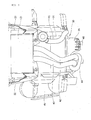
Fig. 3 that represents a view onarrow 3 ofFig. 2 , theoil pan 35 is disposed, in a vehicle front view, on one side in the vehicle width direction (on the right-hand side in the vehicle width direction in the example), whileexhaust pipes internal combustion engine 30 are disposed on the other side in the vehicle width direction. Afin 46 is disposed in a grid pattern on part of theoil pan 35 from a front surface toward a bottom surface thereof. Thefin 46 promotes cooling of theoil pan 35 and increases strength of theoil pan 35. - The
exhaust pipes catalyzer 44 is connected to theexhaust pipes catalyzer 44 undergoes muffling by amuffler 45 disposed on the right of the vehicle body before being discharged. - Referring to
Fig. 2 , thecatalyzer 44 is disposed so as to overlap theoil pan 35 in a vehicle side view. - Referring further to
Fig. 3 , thecoolant return pipe 41 that extends from theradiator 21 is disposed on one side in the vehicle width direction. - Specifically, the
exhaust pipes oil pan 35 are juxtaposed in the vehicle width direction, so that theexhaust pipes exhaust pipes exhaust pipes oil pan 35, theoil pan 35 is affected by heat. If theexhaust pipes oil pan 35 as in the present embodiment, however, cooling performance of theoil pan 35 can be maintained. - Additionally, the
coolant return pipe 41 is disposed on one side in the vehicle width direction, while theexhaust pipes catalyzer 44 is disposed on the other side in the vehicle width direction. Thecoolant return pipe 41 can be spaced away from theexhaust pipes catalyzer 44 having high temperatures, so that a coolant temperature can be prevented from increasing. -
Fig. 4 shows what are shown inFig. 3 to which the undercowl 50 is additionally drawn. - Referring to
Fig. 4 , the undercowl 50 covers theoil pan 35 and thecatalyzer 44 from the forward direction. The undercowl 50 protects thecatalyzer 44 as well as theoil pan 35. As a result, gravel or sand flying from a road surface is less likely to be hit against theoil pan 35 or thecatalyzer 44. - Referring again to
Fig. 2 , anairflow introducing port 56 is disposed on the front side of the sheet inFig. 2 with respect to theexhaust pipe 42 and theexhaust pipe 42 and theairflow introducing port 56 overlap each other in a vehicle side view. Specifically, referring toFig. 4 , theexhaust pipes airflow introducing port 56 are separate in the vehicle width direction, so that the airflow is directed to theexhaust pipes airflow introducing port 56, while the airflow is directed to theoil pan 35 straightly via theairflow introducing port 56. - As a result, the exposed
exhaust pipes oil pan 35 is favorably protected by the undercowl 50, particularly afront surface cover 55. - Referring to
Fig. 5 , the undercowl 50 includes a cowl lefthalf unit 51 and a cowlright half unit 52 which are formed of a resin and split into respective halves, aleft extension 53 which is formed of a resin, connected to a rear portion of the cowl lefthalf unit 51, and extends rearwardly therefrom along the vehicle, aright extension 54 which is formed of a metal, connected to a rear portion of the cowl righthalf unit 52, and extends rearwardly therefrom along the vehicle, and the front surface cover 55 which is integrated with, or removably mounted on, a front portion of the cowl lefthalf unit 51. Thefront surface cover 55 has theairflow introducing port 56. Theright extension 54 covers a side of the catalyzer (reference numeral 44 inFig. 4 ) and is thus exposed to high temperatures. Nonetheless, theright extension 54 is formed of a metal and favorable in terms of heat resistance. - Preferably, a
slit 62 as a long and thin opening is formed between a rear portion of the cowl lefthalf unit 51 and a front portion of theleft extension 53. Aslit 63 is formed between a rear portion of the cowl righthalf unit 52 and a front portion of theright extension 54. Theslits under cowl 50. The airflow flowing in through theairflow introducing port 56 flows rearwardly along the vehicle, while being assisted by the fast airflow flowing through theslits slits under cowl 50. - Preferably, the
front surface cover 55 has an upper flange (reference numeral 57 inFig. 6 ), alower flange 58, aleft flange 59, and a right flange (reference numeral 61 inFig. 6 ) extended rearwardly along the vehicle from respective edges of theairflow introducing port 56. Having theflanges airflow introducing port 56. - Referring to
Fig. 6 , thefront surface cover 55 is inclined such that an upper end thereof is disposed rearwardly of a lower end thereof along the vehicle in a vehicle side view. Theairflow introducing port 56 formed in such afront surface cover 55 opens obliquely upwardly so as to introduce the airflow to theoil pan 35 as shown by an arrow. - While the
upper flange 57 and theright flange 61 extend rearwardly along the vehicle substantially in parallel with a vehicle longitudinal axis, thelower flange 58 is inclined such that a rear portion thereof is disposed upwardly of a front portion thereof. - As a result, the
lower flange 58 is visible in a vehicle front view as shown inFig. 4 , thus narrowing a range over which theoil pan 35 is visible. - Referring also to
Fig. 4 , theairflow introducing port 56 in the undercowl 50 is disposed so as to overlap theoil pan 35 in a vehicle front view. This allows the airflow introduced through theairflow introducing port 56 to be directed straight to theoil pan 35, thus promoting cooling of theoil pan 35. - Referring to
Fig. 6 , theairflow introducing port 56 is open obliquely upwardly such that an upper end thereof is disposed rearwardly of a lower end thereof along the vehicle in a vehicle side view. Since theairflow introducing port 56 is open upwardly, flying gravel or sand from the road surface is less likely to enter theairflow introducing port 56, so that, for example, the flying gravel is less likely to hit against theoil pan 35. - Additionally, though the
airflow introducing port 56 is open obliquely upwardly, thelower flange 58 is visible when theairflow introducing port 56 is viewed from above as shown inFig. 5 . Specifically, theoil pan 35 is not readily visible through theairflow introducing port 56 in a plan view, which enhances appearance. - Referring to
Fig. 6 , the cowl lefthalf unit 51 is dogleg-shaped (a V-shape turned sideways to protrude forwardly) in a side view with the front surface cover 55 attached. An upper half portion of the dogleg shape is formed with thefront surface cover 55 and a lower half portion of the dogleg shape is aninclined surface 51 a extending obliquely downwardly toward the rear (or obliquely upwardly toward the front). - The under
cowl 50 is substantially shaped like a cone. This enhances windbreak performance and reduces running resistance. Additionally, a good part of gravel and other objects flying from the road surface hits against theinclined surface 51 a. Since theinclined surface 51 a is inclined, flying gravel and other objects are quickly returned back to the road surface. Thus, theoil pan 35 is favorably cooled by the airflow and protected from flying gravel and other objects. - The saddle riding type vehicle according to the present invention has been applied to a motorcycle in the embodiment. The saddle riding type vehicle according to the present invention may nonetheless be applied to saddle riding type three-wheeled or four-wheeled vehicles.
- The present invention is suitable for under cowls of saddle riding type vehicles.
- The present invention is directed to provide an under cowl structure that can enhance cooling performance of an oil pan, while retaining favorable appearance.
- A
front surface cover 55 is inclined such that an upper end thereof is disposed rearwardly of a lower end thereof along a vehicle in a vehicle side view. Anairflow introducing port 56 formed in such afront surface cover 55 opens obliquely upwardly so as to introduce airflow to anoil pan 35 as shown by an arrow. While anupper flange 57 and aright flange 61 extend rearwardly along a vehicle substantially in parallel with a vehicle longitudinal axis, alower flange 58 is inclined such that a rear portion thereof is disposed upwardly of a front portion thereof. - Airflow can be directed straight to the oil pan despite the presence of the under cowl. The inclined lower flange makes the oil pan less easily visible when viewed from above or front, thus achieving enhanced appearance.
- To provide an under cowl structure that can enhance cooling performance of an oil pan, while retaining favorable appearance.
- A front surface cover (55) is inclined such that an upper end thereof is disposed rearwardly of a lower end thereof along a vehicle in a vehicle side view. An airflow introducing port (56) formed in such a front surface cover (55) opens obliquely upwardly so as to introduce airflow to an oil pan (35) as shown by an arrow. While an upper flange (57) and a right flange (61) extend rearwardly along a vehicle substantially in parallel with a vehicle longitudinal axis, a lower flange (58) is inclined such that a rear portion thereof is disposed upwardly of a front portion thereof.
- Airflow can be directed straight to the oil pan despite the presence of the under cowl. The inclined lower flange makes the oil pan less easily visible when viewed from above or front, thus achieving enhanced appearance.
Claims (6)
- A saddle riding type vehicle in which an internal combustion engine (30) is supported on a vehicle body frame (40), an oil pan (35) is provided at a lower portion of the internal combustion engine (30), and an under cowl (50) covers an area forward of the oil pan (35), wherein
the under cowl (50) has an airflow introducing port (56) that opens at a position overlapping the oil pan (35) in a vehicle front view and opens obliquely upwardly such that an upper end of the airflow introducing port (56) is disposed rearwardly of a lower end thereof along a vehicle in a vehicle side view to thereby introduce airflow to the oil pan (35). - The saddle riding type vehicle according to claim 1, wherein upper and lower flanges (57 and 58) and left and right flanges (59 and 61) extend rearwardly along the vehicle from edges of the airflow introducing port (56).
- The saddle riding type vehicle according to claim 2, wherein the lower flange (58) is inclined such that a rear portion thereof is disposed upwardly of a front portion thereof.
- The saddle riding type vehicle according to any one of claims 1 to 3,
wherein
in a vehicle front view, the oil pan (35) is disposed on one side in a vehicle width direction, and exhaust pipes (42 and 43) extending from the internal combustion engine (30) are disposed on the other side in the vehicle width direction, and
in a vehicle side view, the exhaust pipes (42 and 43) overlap the airflow introducing port (56). - The saddle riding type vehicle according to claim 4, wherein
a catalyzer (44) for purifying exhaust gas is disposed on the exhaust pipes (42 and 43), the catalyzer (44) being disposed at a position overlapping the oil pan (35) in a vehicle side view, and
the exhaust pipes (42 and 43) from the internal combustion engine (30) to the catalyzer (44) are bent toward the other side in the vehicle width direction from a vehicle body center in a vehicle front view. - The saddle riding type vehicle according to claim 4 or 5, wherein a coolant return pipe (41) extending from a radiator (21) is disposed on the one side in the vehicle width direction in a vehicle front view.
Applications Claiming Priority (1)
| Application Number | Priority Date | Filing Date | Title |
|---|---|---|---|
| JP2012031859A JP5932382B2 (en) | 2012-02-16 | 2012-02-16 | Saddle riding vehicle |
Publications (2)
| Publication Number | Publication Date |
|---|---|
| EP2628670A1 true EP2628670A1 (en) | 2013-08-21 |
| EP2628670B1 EP2628670B1 (en) | 2014-04-02 |
Family
ID=47227522
Family Applications (1)
| Application Number | Title | Priority Date | Filing Date |
|---|---|---|---|
| EP12192013.6A Not-in-force EP2628670B1 (en) | 2012-02-16 | 2012-11-09 | Saddle riding type vehicle |
Country Status (3)
| Country | Link |
|---|---|
| EP (1) | EP2628670B1 (en) |
| JP (1) | JP5932382B2 (en) |
| BR (1) | BR102013003442A2 (en) |
Cited By (1)
| Publication number | Priority date | Publication date | Assignee | Title |
|---|---|---|---|---|
| CN106005136B (en) * | 2015-03-31 | 2019-01-04 | 本田技研工业株式会社 | The lower cover structure of saddle ride type vehicle |
Families Citing this family (1)
| Publication number | Priority date | Publication date | Assignee | Title |
|---|---|---|---|---|
| JP7238008B2 (en) * | 2021-03-29 | 2023-03-13 | 本田技研工業株式会社 | saddle-riding vehicle |
Citations (3)
| Publication number | Priority date | Publication date | Assignee | Title |
|---|---|---|---|---|
| JP2007118653A (en) * | 2005-10-25 | 2007-05-17 | Honda Motor Co Ltd | Engine cooling structure for saddle riding type vehicles |
| JP2009113654A (en) * | 2007-11-07 | 2009-05-28 | Yamaha Motor Co Ltd | Motorcycle |
| JP2011074801A (en) | 2009-09-30 | 2011-04-14 | Honda Motor Co Ltd | Arrangement structure for evaporated fuel treatment device of saddle-type vehicle |
Family Cites Families (3)
| Publication number | Priority date | Publication date | Assignee | Title |
|---|---|---|---|---|
| JP2004116375A (en) * | 2002-09-25 | 2004-04-15 | Yamaha Motor Co Ltd | Sound insulation structure of forced air-cooled engine for motorcycle |
| JP5568890B2 (en) * | 2009-06-02 | 2014-08-13 | スズキ株式会社 | Oil breather device for motorcycle engines |
| JP5496579B2 (en) * | 2009-08-28 | 2014-05-21 | 本田技研工業株式会社 | Cover structure of saddle-ride type vehicle |
-
2012
- 2012-02-16 JP JP2012031859A patent/JP5932382B2/en not_active Expired - Fee Related
- 2012-11-09 EP EP12192013.6A patent/EP2628670B1/en not_active Not-in-force
-
2013
- 2013-02-14 BR BRBR102013003442-8A patent/BR102013003442A2/en not_active Application Discontinuation
Patent Citations (3)
| Publication number | Priority date | Publication date | Assignee | Title |
|---|---|---|---|---|
| JP2007118653A (en) * | 2005-10-25 | 2007-05-17 | Honda Motor Co Ltd | Engine cooling structure for saddle riding type vehicles |
| JP2009113654A (en) * | 2007-11-07 | 2009-05-28 | Yamaha Motor Co Ltd | Motorcycle |
| JP2011074801A (en) | 2009-09-30 | 2011-04-14 | Honda Motor Co Ltd | Arrangement structure for evaporated fuel treatment device of saddle-type vehicle |
Cited By (1)
| Publication number | Priority date | Publication date | Assignee | Title |
|---|---|---|---|---|
| CN106005136B (en) * | 2015-03-31 | 2019-01-04 | 本田技研工业株式会社 | The lower cover structure of saddle ride type vehicle |
Also Published As
| Publication number | Publication date |
|---|---|
| EP2628670B1 (en) | 2014-04-02 |
| JP5932382B2 (en) | 2016-06-08 |
| JP2013167224A (en) | 2013-08-29 |
| BR102013003442A2 (en) | 2015-06-16 |
Similar Documents
| Publication | Publication Date | Title |
|---|---|---|
| US8146693B2 (en) | Motorcycle and intake device thereof | |
| US9663175B2 (en) | Front fender structure for saddle-ride type vehicle | |
| EP1612378A2 (en) | Muffler Device | |
| JP6649083B2 (en) | Motorcycle | |
| JP4856485B2 (en) | Motorcycle cowling structure | |
| JP2006240315A (en) | Saddle riding vehicle | |
| JP2009107569A (en) | Motorcycle cowl and motorcycle | |
| US8322479B2 (en) | Covering for motorcycle exhaust tube | |
| EP2161187B1 (en) | Motorcycle | |
| TWM474689U (en) | Windproof structure of straddle type vehicle | |
| EP2889207A1 (en) | Motorcycle | |
| EP2562069B1 (en) | Saddle-riding type automotive vehicle | |
| JP5576308B2 (en) | Saddle riding | |
| JP5460376B2 (en) | Saddle riding vehicle | |
| EP2628670B1 (en) | Saddle riding type vehicle | |
| JP2012187974A (en) | Cowling device for motorcycle | |
| JP2024155427A (en) | Under cowl | |
| JP2018075934A (en) | Saddle-riding type vehicle | |
| JP6003477B2 (en) | Handle cover device for motorcycle | |
| EP2075188B1 (en) | Straddle-type vehicle | |
| JPWO2017057340A1 (en) | Saddle riding | |
| EP3964432B1 (en) | Front cowl | |
| JP4579127B2 (en) | Engine cooling structure for saddle riding type vehicles | |
| JP7216134B2 (en) | saddle-riding vehicle | |
| JP7661386B2 (en) | Saddle-type vehicle |
Legal Events
| Date | Code | Title | Description |
|---|---|---|---|
| PUAI | Public reference made under article 153(3) epc to a published international application that has entered the european phase |
Free format text: ORIGINAL CODE: 0009012 |
|
| 17P | Request for examination filed |
Effective date: 20121109 |
|
| AK | Designated contracting states |
Kind code of ref document: A1 Designated state(s): AL AT BE BG CH CY CZ DE DK EE ES FI FR GB GR HR HU IE IS IT LI LT LU LV MC MK MT NL NO PL PT RO RS SE SI SK SM TR |
|
| AX | Request for extension of the european patent |
Extension state: BA ME |
|
| GRAP | Despatch of communication of intention to grant a patent |
Free format text: ORIGINAL CODE: EPIDOSNIGR1 |
|
| RIC1 | Information provided on ipc code assigned before grant |
Ipc: F01M 5/00 20060101ALI20130930BHEP Ipc: B62J 17/02 20060101ALI20130930BHEP Ipc: B62J 17/00 20060101AFI20130930BHEP Ipc: B62J 23/00 20060101ALI20130930BHEP |
|
| INTG | Intention to grant announced |
Effective date: 20131024 |
|
| RIN1 | Information on inventor provided before grant (corrected) |
Inventor name: NAGATA, MASATO C/O HONDA R&D CO., LTD. Inventor name: TSUKUI, HIROAKI C/O HONDA R&D CO., LTD. |
|
| GRAS | Grant fee paid |
Free format text: ORIGINAL CODE: EPIDOSNIGR3 |
|
| GRAA | (expected) grant |
Free format text: ORIGINAL CODE: 0009210 |
|
| AK | Designated contracting states |
Kind code of ref document: B1 Designated state(s): AL AT BE BG CH CY CZ DE DK EE ES FI FR GB GR HR HU IE IS IT LI LT LU LV MC MK MT NL NO PL PT RO RS SE SI SK SM TR |
|
| REG | Reference to a national code |
Ref country code: GB Ref legal event code: FG4D |
|
| REG | Reference to a national code |
Ref country code: AT Ref legal event code: REF Ref document number: 659911 Country of ref document: AT Kind code of ref document: T Effective date: 20140415 Ref country code: CH Ref legal event code: EP |
|
| REG | Reference to a national code |
Ref country code: IE Ref legal event code: FG4D |
|
| REG | Reference to a national code |
Ref country code: DE Ref legal event code: R096 Ref document number: 602012001290 Country of ref document: DE Effective date: 20140515 |
|
| REG | Reference to a national code |
Ref country code: AT Ref legal event code: MK05 Ref document number: 659911 Country of ref document: AT Kind code of ref document: T Effective date: 20140402 |
|
| REG | Reference to a national code |
Ref country code: NL Ref legal event code: VDEP Effective date: 20140402 |
|
| REG | Reference to a national code |
Ref country code: LT Ref legal event code: MG4D |
|
| PG25 | Lapsed in a contracting state [announced via postgrant information from national office to epo] |
Ref country code: FI Free format text: LAPSE BECAUSE OF FAILURE TO SUBMIT A TRANSLATION OF THE DESCRIPTION OR TO PAY THE FEE WITHIN THE PRESCRIBED TIME-LIMIT Effective date: 20140402 Ref country code: LT Free format text: LAPSE BECAUSE OF FAILURE TO SUBMIT A TRANSLATION OF THE DESCRIPTION OR TO PAY THE FEE WITHIN THE PRESCRIBED TIME-LIMIT Effective date: 20140402 Ref country code: IS Free format text: LAPSE BECAUSE OF FAILURE TO SUBMIT A TRANSLATION OF THE DESCRIPTION OR TO PAY THE FEE WITHIN THE PRESCRIBED TIME-LIMIT Effective date: 20140802 Ref country code: BG Free format text: LAPSE BECAUSE OF FAILURE TO SUBMIT A TRANSLATION OF THE DESCRIPTION OR TO PAY THE FEE WITHIN THE PRESCRIBED TIME-LIMIT Effective date: 20140702 Ref country code: GR Free format text: LAPSE BECAUSE OF FAILURE TO SUBMIT A TRANSLATION OF THE DESCRIPTION OR TO PAY THE FEE WITHIN THE PRESCRIBED TIME-LIMIT Effective date: 20140703 Ref country code: NO Free format text: LAPSE BECAUSE OF FAILURE TO SUBMIT A TRANSLATION OF THE DESCRIPTION OR TO PAY THE FEE WITHIN THE PRESCRIBED TIME-LIMIT Effective date: 20140702 Ref country code: CY Free format text: LAPSE BECAUSE OF FAILURE TO SUBMIT A TRANSLATION OF THE DESCRIPTION OR TO PAY THE FEE WITHIN THE PRESCRIBED TIME-LIMIT Effective date: 20140402 Ref country code: NL Free format text: LAPSE BECAUSE OF FAILURE TO SUBMIT A TRANSLATION OF THE DESCRIPTION OR TO PAY THE FEE WITHIN THE PRESCRIBED TIME-LIMIT Effective date: 20140402 Ref country code: CZ Free format text: LAPSE BECAUSE OF FAILURE TO SUBMIT A TRANSLATION OF THE DESCRIPTION OR TO PAY THE FEE WITHIN THE PRESCRIBED TIME-LIMIT Effective date: 20140402 |
|
| PG25 | Lapsed in a contracting state [announced via postgrant information from national office to epo] |
Ref country code: AT Free format text: LAPSE BECAUSE OF FAILURE TO SUBMIT A TRANSLATION OF THE DESCRIPTION OR TO PAY THE FEE WITHIN THE PRESCRIBED TIME-LIMIT Effective date: 20140402 Ref country code: PL Free format text: LAPSE BECAUSE OF FAILURE TO SUBMIT A TRANSLATION OF THE DESCRIPTION OR TO PAY THE FEE WITHIN THE PRESCRIBED TIME-LIMIT Effective date: 20140402 Ref country code: HR Free format text: LAPSE BECAUSE OF FAILURE TO SUBMIT A TRANSLATION OF THE DESCRIPTION OR TO PAY THE FEE WITHIN THE PRESCRIBED TIME-LIMIT Effective date: 20140402 Ref country code: LV Free format text: LAPSE BECAUSE OF FAILURE TO SUBMIT A TRANSLATION OF THE DESCRIPTION OR TO PAY THE FEE WITHIN THE PRESCRIBED TIME-LIMIT Effective date: 20140402 Ref country code: SE Free format text: LAPSE BECAUSE OF FAILURE TO SUBMIT A TRANSLATION OF THE DESCRIPTION OR TO PAY THE FEE WITHIN THE PRESCRIBED TIME-LIMIT Effective date: 20140402 Ref country code: ES Free format text: LAPSE BECAUSE OF FAILURE TO SUBMIT A TRANSLATION OF THE DESCRIPTION OR TO PAY THE FEE WITHIN THE PRESCRIBED TIME-LIMIT Effective date: 20140402 Ref country code: RS Free format text: LAPSE BECAUSE OF FAILURE TO SUBMIT A TRANSLATION OF THE DESCRIPTION OR TO PAY THE FEE WITHIN THE PRESCRIBED TIME-LIMIT Effective date: 20140402 |
|
| PG25 | Lapsed in a contracting state [announced via postgrant information from national office to epo] |
Ref country code: PT Free format text: LAPSE BECAUSE OF FAILURE TO SUBMIT A TRANSLATION OF THE DESCRIPTION OR TO PAY THE FEE WITHIN THE PRESCRIBED TIME-LIMIT Effective date: 20140804 |
|
| REG | Reference to a national code |
Ref country code: DE Ref legal event code: R097 Ref document number: 602012001290 Country of ref document: DE |
|
| PG25 | Lapsed in a contracting state [announced via postgrant information from national office to epo] |
Ref country code: SK Free format text: LAPSE BECAUSE OF FAILURE TO SUBMIT A TRANSLATION OF THE DESCRIPTION OR TO PAY THE FEE WITHIN THE PRESCRIBED TIME-LIMIT Effective date: 20140402 Ref country code: DK Free format text: LAPSE BECAUSE OF FAILURE TO SUBMIT A TRANSLATION OF THE DESCRIPTION OR TO PAY THE FEE WITHIN THE PRESCRIBED TIME-LIMIT Effective date: 20140402 Ref country code: BE Free format text: LAPSE BECAUSE OF FAILURE TO SUBMIT A TRANSLATION OF THE DESCRIPTION OR TO PAY THE FEE WITHIN THE PRESCRIBED TIME-LIMIT Effective date: 20140402 Ref country code: EE Free format text: LAPSE BECAUSE OF FAILURE TO SUBMIT A TRANSLATION OF THE DESCRIPTION OR TO PAY THE FEE WITHIN THE PRESCRIBED TIME-LIMIT Effective date: 20140402 Ref country code: RO Free format text: LAPSE BECAUSE OF FAILURE TO SUBMIT A TRANSLATION OF THE DESCRIPTION OR TO PAY THE FEE WITHIN THE PRESCRIBED TIME-LIMIT Effective date: 20140402 |
|
| PLBE | No opposition filed within time limit |
Free format text: ORIGINAL CODE: 0009261 |
|
| STAA | Information on the status of an ep patent application or granted ep patent |
Free format text: STATUS: NO OPPOSITION FILED WITHIN TIME LIMIT |
|
| 26N | No opposition filed |
Effective date: 20150106 |
|
| REG | Reference to a national code |
Ref country code: DE Ref legal event code: R097 Ref document number: 602012001290 Country of ref document: DE Effective date: 20150106 |
|
| PG25 | Lapsed in a contracting state [announced via postgrant information from national office to epo] |
Ref country code: RS Free format text: LAPSE BECAUSE OF FAILURE TO SUBMIT A TRANSLATION OF THE DESCRIPTION OR TO PAY THE FEE WITHIN THE PRESCRIBED TIME-LIMIT Effective date: 20141119 |
|
| PG25 | Lapsed in a contracting state [announced via postgrant information from national office to epo] |
Ref country code: LU Free format text: LAPSE BECAUSE OF FAILURE TO SUBMIT A TRANSLATION OF THE DESCRIPTION OR TO PAY THE FEE WITHIN THE PRESCRIBED TIME-LIMIT Effective date: 20141109 Ref country code: MC Free format text: LAPSE BECAUSE OF FAILURE TO SUBMIT A TRANSLATION OF THE DESCRIPTION OR TO PAY THE FEE WITHIN THE PRESCRIBED TIME-LIMIT Effective date: 20140402 |
|
| PG25 | Lapsed in a contracting state [announced via postgrant information from national office to epo] |
Ref country code: SI Free format text: LAPSE BECAUSE OF FAILURE TO SUBMIT A TRANSLATION OF THE DESCRIPTION OR TO PAY THE FEE WITHIN THE PRESCRIBED TIME-LIMIT Effective date: 20140402 |
|
| REG | Reference to a national code |
Ref country code: IE Ref legal event code: MM4A |
|
| REG | Reference to a national code |
Ref country code: FR Ref legal event code: PLFP Year of fee payment: 4 |
|
| PG25 | Lapsed in a contracting state [announced via postgrant information from national office to epo] |
Ref country code: IE Free format text: LAPSE BECAUSE OF NON-PAYMENT OF DUE FEES Effective date: 20141109 |
|
| REG | Reference to a national code |
Ref country code: CH Ref legal event code: PL |
|
| PG25 | Lapsed in a contracting state [announced via postgrant information from national office to epo] |
Ref country code: HU Free format text: LAPSE BECAUSE OF FAILURE TO SUBMIT A TRANSLATION OF THE DESCRIPTION OR TO PAY THE FEE WITHIN THE PRESCRIBED TIME-LIMIT; INVALID AB INITIO Effective date: 20121109 Ref country code: MT Free format text: LAPSE BECAUSE OF FAILURE TO SUBMIT A TRANSLATION OF THE DESCRIPTION OR TO PAY THE FEE WITHIN THE PRESCRIBED TIME-LIMIT Effective date: 20140402 Ref country code: CH Free format text: LAPSE BECAUSE OF NON-PAYMENT OF DUE FEES Effective date: 20151130 Ref country code: TR Free format text: LAPSE BECAUSE OF FAILURE TO SUBMIT A TRANSLATION OF THE DESCRIPTION OR TO PAY THE FEE WITHIN THE PRESCRIBED TIME-LIMIT Effective date: 20140402 Ref country code: LI Free format text: LAPSE BECAUSE OF NON-PAYMENT OF DUE FEES Effective date: 20151130 |
|
| REG | Reference to a national code |
Ref country code: FR Ref legal event code: PLFP Year of fee payment: 5 |
|
| PG25 | Lapsed in a contracting state [announced via postgrant information from national office to epo] |
Ref country code: SM Free format text: LAPSE BECAUSE OF FAILURE TO SUBMIT A TRANSLATION OF THE DESCRIPTION OR TO PAY THE FEE WITHIN THE PRESCRIBED TIME-LIMIT Effective date: 20140402 |
|
| GBPC | Gb: european patent ceased through non-payment of renewal fee |
Effective date: 20161109 |
|
| REG | Reference to a national code |
Ref country code: FR Ref legal event code: PLFP Year of fee payment: 6 |
|
| PG25 | Lapsed in a contracting state [announced via postgrant information from national office to epo] |
Ref country code: GB Free format text: LAPSE BECAUSE OF NON-PAYMENT OF DUE FEES Effective date: 20161109 |
|
| PG25 | Lapsed in a contracting state [announced via postgrant information from national office to epo] |
Ref country code: MK Free format text: LAPSE BECAUSE OF FAILURE TO SUBMIT A TRANSLATION OF THE DESCRIPTION OR TO PAY THE FEE WITHIN THE PRESCRIBED TIME-LIMIT Effective date: 20140402 |
|
| REG | Reference to a national code |
Ref country code: FR Ref legal event code: PLFP Year of fee payment: 7 |
|
| PG25 | Lapsed in a contracting state [announced via postgrant information from national office to epo] |
Ref country code: AL Free format text: LAPSE BECAUSE OF FAILURE TO SUBMIT A TRANSLATION OF THE DESCRIPTION OR TO PAY THE FEE WITHIN THE PRESCRIBED TIME-LIMIT Effective date: 20140402 |
|
| PGFP | Annual fee paid to national office [announced via postgrant information from national office to epo] |
Ref country code: IT Payment date: 20181122 Year of fee payment: 7 Ref country code: FR Payment date: 20181011 Year of fee payment: 7 |
|
| REG | Reference to a national code |
Ref country code: DE Ref legal event code: R084 Ref document number: 602012001290 Country of ref document: DE |
|
| PGFP | Annual fee paid to national office [announced via postgrant information from national office to epo] |
Ref country code: DE Payment date: 20191029 Year of fee payment: 8 |
|
| PG25 | Lapsed in a contracting state [announced via postgrant information from national office to epo] |
Ref country code: FR Free format text: LAPSE BECAUSE OF NON-PAYMENT OF DUE FEES Effective date: 20191130 Ref country code: IT Free format text: LAPSE BECAUSE OF NON-PAYMENT OF DUE FEES Effective date: 20191109 |
|
| REG | Reference to a national code |
Ref country code: DE Ref legal event code: R119 Ref document number: 602012001290 Country of ref document: DE |
|
| PG25 | Lapsed in a contracting state [announced via postgrant information from national office to epo] |
Ref country code: DE Free format text: LAPSE BECAUSE OF NON-PAYMENT OF DUE FEES Effective date: 20210601 |