EP2628638A2 - Automotive body element comprising a light source on its inner face - Google Patents
Automotive body element comprising a light source on its inner face Download PDFInfo
- Publication number
- EP2628638A2 EP2628638A2 EP13155528.6A EP13155528A EP2628638A2 EP 2628638 A2 EP2628638 A2 EP 2628638A2 EP 13155528 A EP13155528 A EP 13155528A EP 2628638 A2 EP2628638 A2 EP 2628638A2
- Authority
- EP
- European Patent Office
- Prior art keywords
- coating layer
- light source
- body element
- additional coating
- opening
- Prior art date
- Legal status (The legal status is an assumption and is not a legal conclusion. Google has not performed a legal analysis and makes no representation as to the accuracy of the status listed.)
- Granted
Links
- 239000011247 coating layer Substances 0.000 claims abstract description 104
- 239000000463 material Substances 0.000 claims abstract description 16
- 239000010410 layer Substances 0.000 claims description 50
- VYZAMTAEIAYCRO-UHFFFAOYSA-N Chromium Chemical compound [Cr] VYZAMTAEIAYCRO-UHFFFAOYSA-N 0.000 claims description 21
- 239000003973 paint Substances 0.000 claims description 19
- 238000000034 method Methods 0.000 claims description 11
- 239000002966 varnish Substances 0.000 claims description 10
- 238000004519 manufacturing process Methods 0.000 claims description 8
- 239000011248 coating agent Substances 0.000 claims description 2
- 238000000576 coating method Methods 0.000 claims description 2
- 238000005240 physical vapour deposition Methods 0.000 description 5
- 238000001746 injection moulding Methods 0.000 description 3
- 238000004544 sputter deposition Methods 0.000 description 3
- 239000012780 transparent material Substances 0.000 description 3
- 239000004743 Polypropylene Substances 0.000 description 2
- 238000004026 adhesive bonding Methods 0.000 description 2
- 238000003486 chemical etching Methods 0.000 description 2
- 239000000835 fiber Substances 0.000 description 2
- 238000010329 laser etching Methods 0.000 description 2
- 229920003229 poly(methyl methacrylate) Polymers 0.000 description 2
- 239000004417 polycarbonate Substances 0.000 description 2
- 239000004926 polymethyl methacrylate Substances 0.000 description 2
- 229920001155 polypropylene Polymers 0.000 description 2
- 239000000126 substance Substances 0.000 description 2
- 239000000758 substrate Substances 0.000 description 2
- 239000004676 acrylonitrile butadiene styrene Substances 0.000 description 1
- 238000005034 decoration Methods 0.000 description 1
- 239000000428 dust Substances 0.000 description 1
- 238000000465 moulding Methods 0.000 description 1
- 239000012994 photoredox catalyst Substances 0.000 description 1
- 229920000515 polycarbonate Polymers 0.000 description 1
- -1 polypropylene Polymers 0.000 description 1
- 239000012815 thermoplastic material Substances 0.000 description 1
- 229920006352 transparent thermoplastic Polymers 0.000 description 1
Images
Classifications
-
- B—PERFORMING OPERATIONS; TRANSPORTING
- B60—VEHICLES IN GENERAL
- B60Q—ARRANGEMENT OF SIGNALLING OR LIGHTING DEVICES, THE MOUNTING OR SUPPORTING THEREOF OR CIRCUITS THEREFOR, FOR VEHICLES IN GENERAL
- B60Q1/00—Arrangement of optical signalling or lighting devices, the mounting or supporting thereof or circuits therefor
- B60Q1/26—Arrangement of optical signalling or lighting devices, the mounting or supporting thereof or circuits therefor the devices being primarily intended to indicate the vehicle, or parts thereof, or to give signals, to other traffic
-
- B—PERFORMING OPERATIONS; TRANSPORTING
- B60—VEHICLES IN GENERAL
- B60Q—ARRANGEMENT OF SIGNALLING OR LIGHTING DEVICES, THE MOUNTING OR SUPPORTING THEREOF OR CIRCUITS THEREFOR, FOR VEHICLES IN GENERAL
- B60Q1/00—Arrangement of optical signalling or lighting devices, the mounting or supporting thereof or circuits therefor
- B60Q1/26—Arrangement of optical signalling or lighting devices, the mounting or supporting thereof or circuits therefor the devices being primarily intended to indicate the vehicle, or parts thereof, or to give signals, to other traffic
- B60Q1/2661—Arrangement of optical signalling or lighting devices, the mounting or supporting thereof or circuits therefor the devices being primarily intended to indicate the vehicle, or parts thereof, or to give signals, to other traffic mounted on parts having other functions
Landscapes
- Engineering & Computer Science (AREA)
- Mechanical Engineering (AREA)
- Illuminated Signs And Luminous Advertising (AREA)
- Vehicle Interior And Exterior Ornaments, Soundproofing, And Insulation (AREA)
- Vehicle Waterproofing, Decoration, And Sanitation Devices (AREA)
- Lighting Device Outwards From Vehicle And Optical Signal (AREA)
- Non-Portable Lighting Devices Or Systems Thereof (AREA)
Abstract
Description
- The present invention relates to an automotive body element comprising a translucent body having an outer face, intended to be turned towards outside the vehicle, and an inner face, intended to be turned towards inside the vehicle, at least one of said faces being coated by a coating layer made of opaque material.
- The invention also relates to a method for producing such a body element.
- In order to improve the appearance of an automotive vehicle, it is known to provide luminous elements arranged to illuminate the body of the vehicle. These luminous elements are for example formed by light guides arranged along air inlets of the vehicle, for example around an air inlet grid, or forming a logo or along the door openings, etc. The light sources of such luminous elements are arranged in openings provided in body elements or between adjacent body elements and are directly visible from the outside of the vehicle.
- Therefore, the appearance of the vehicle is improved when the light sources are turned on, but these light sources remain visible from outside the vehicle when they are turned off, which negatively impacts on the appearance of the vehicle.
- The same issue may arise with functional light sources, such as stop lights or other lights.
- It is also known to perform multistep processes for the manufacture of decorative rods, such as chromed ornamental strips of automotive bumpers. Such processes generally involve the injection-moulding of a substrate, followed by galvanisation of the substrate in several chemical baths.
- A further known process consists of film-insert moulding. A coated film is trimmed, formed and then injection-moulded. The resulting product is opaque.
- The known chroming of body components leads to a chrome layer thickness incompatible with backlighting applications. Backlighting is only possible by intentionally destroying the visible surface.
- One of the goals of the invention is to overcome the above-mentioned drawbacks by proposing a body element having an outer face which can be illuminated without the light source being visible from outside of the vehicle when it is turned off.
- To this end, the invention relates to a body element of the afore-mentioned type, wherein said coating layer comprises at least one opening, said element further comprising at least one light source extending on the inner face of the body opposite the opening, an additional coating layer made of opaque material being arranged on the body element on the outer face side of the translucent body at least opposite the opening, said additional coating layer being arranged to let the light coming from the light source pass through said additional coating layer, when the light source is turned on, and to prevent natural light to pass through the additional coating layer when the light source is turned off.
- The light source is hidden by the body element and is therefore not directly visible from outside the vehicle. Furthermore, the additional coating layer prevents natural light from reaching the light source, when said light source is turned off. Consequently, the appearance of the vehicle is not negatively impacted when the light source is turned off and is improved when it is turned on. Furthermore, the invention offers a greater liberty in the arrangement of the light sources, said light sources not needing to be arranged in specific openings or places between the body elements.
- According to other features of the body element according to the invention:
- the additional coating layer extends continuously on the outer face side of the body and has no opening.
- the coating layer comprises a paint or chrome layer.
- the additional coating layer is a paint or chrome layer having a reflective outer face;
- the light source is formed by a light guide extending on the inner face of the body, a light emitting element being connected to at least one of the extreme part of said light guide;
- the body element comprises a translucent varnish layer extending on the additional coating layer;
- the coating layer extends on the outer face of the body, the additional coating layer extending on said coating layer ;
- the coating layer further comprises a primer layer arranged on the outer face of the body;
- the coating layer extends on the inner face of the body; and
- the light source is arranged in the opening of the coating layer.
- The invention also relates to a method for producing a body element as described above, the method comprising the following steps:
- providing a body made of translucent material,
- coating the inner face or the outer face of said body by a coating layer made of opaque material,
- providing an opening in the coating layer,
- attaching a light source on the inner face of the body,
- providing an additional coating layer made of opaque material arranged on the body element on the outer face side of the body at least opposite the opening, said additional coating layer being arranged to let the light coming from the light source pass through said additional coating layer, when the light source is turned, on and to prevent natural light to pass through the additional coating layer when the light source is turned off.
- Other aspects and advantages of the invention will appear upon reading the following description, given by way of example and made in reference to the appended drawings, wherein :
-
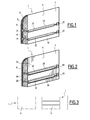
Fig. 1 is a diagrammatical perspective and partially cross-section view of part of a body element according to a first embodiment of the invention, -
Fig. 2 is a diagrammatical perspective and partially cross-section view of part of a body element according to a second embodiment of the invention, -
Fig. 3 is a diagrammatical front view of the body element according to the first and second embodiments of the invention when the light source is turned off (on the left) and when it is turned on (on the right), -
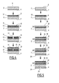
Fig. 4 is a diagrammatical cross-section view of the different steps of the method for producing a body element according to the first embodiment of the invention, and -
Fig. 5 is a diagrammatical cross-section view of the different steps of the method for producing a body element according to the second embodiment of the invention. - Referring to
Figs. 1 and 2 , an automotivevehicle body element 1 will be described. By body element, it is meant any element intended to extend toward the outside of the vehicle, such as a trim element, a decoration element of the decorative cover, medallion, decorative rod or air inlet grid type or other. - The
body element 1 comprises abody 2 defining the shape and the thickness of the body element. Therefore, in the case of a rod for example, thebody 2 will be substantially of parallelepipedic and elongated shape. Thus, the shape and thickness of thebody 2 depend on the type ofbody element 1 it is intended to form and can vary from onebody element 1 to another. - The
body 2 comprises aninner face 4, intended to be turned towards the inside of the automotive vehicle, and anouter face 6, intended to be turned towards the outside of the vehicle, i.e. to extend outside the vehicle and to be visible from the outside of the vehicle. - The
body 2 is made in a translucent or transparent material, i.e. a material allowing light to pass from theinner face 4 to theouter face 6 and vice-versa. Thebody 2 is for example made of one or more translucent or transparent thermoplastic materials, such as acrylonitrile butadiene styrene (ABS), polycarbonate (PC), ABS-PC, polymethyl methacrylate (PMMA), polypropylene (PP) or other or a mix of these materials. - Referring to
Figs. 1 and4 , it will now be described a first embodiment of the invention. - In the first embodiment, the
outer face 6 of thebody 2 is coated by an at least partiallyopaque coating layer 8, i.e. not letting the light coming from the body pass towards the outside of the body element, or coming from the outside of the body element pass towards thebody 2. Thecoating layer 8 covers the entireouter face 6 of thebody 2. - The
coating layer 8 comprises at least a paint orchrome layer 10. - According to an embodiment, the
coating layer 8 further comprise aprimer layer 12, improving in a known way the adhesion of the paint orchrome layer 10 on the body. Theprimer layer 12 is arranged directly on theouter face 6 of thebody 2 and the paint or chrome layer extends on theprimer layer 12 opposite theouter face 6 of thebody 2, as shown inFig. 4 . - The
coating layer 8 comprises at least one opening 14 passing through saidcoating layer 8, i.e. passing through the paint or chrome layer and, if needed, theprimer layer 12. On the side of the outer face6 of thebody 2, theopening 14 is closed by thebody 2. Therefore, the light passing through thebody 2 can be diffused towards the outside of thebody element 1 through theopening 14. As way of example, theopening 14 has a width comprised between 1 micrometer and a few millimetres. - The
opening 14 can have any desired shape in order to create a pattern on the outer face of thebody element 1 as will be described later. Severaldistinct openings 14 can be provided to create the pattern, as shown inFig. 1 . - An
additional coating layer 15 is arranged on thecoating layer 8 and fills theopening 14. Theadditional layer 15 has no opening and is substantially uniform all over thecoating layer 8. Theadditional coating layer 15 gives its outer aspect to thebody element 1. The outer face of theadditional layer 15 is reflective such that light coming from the outside of the vehicle does not pass through theadditional coating layer 15 into thecoating layer 8. Therefore, theopening 14 and thebody 2 are not visible from outside thebody element 1. The thickness of theadditional coating layer 15 is arranged to let the light coming from a light source arranged on theinner face 4 of thebody 2 pass through theadditional coating layer 15 towards outside the body element when the light source is turned on, as will be described later, whereas light coming from outside does not make the elements extending on theinner face 4 of the body visible as explained previously. - Consequently, from outside the
body element 1, an observer only sees the uniformadditional coating layer 15 and does not perceive the presence of elements behind thebody 2 or the presence of the pattern designed by the opening(s) 14, when thebody element 1 is illuminated by natural light. For this observer, thebody element 1 has therefore a uniform aspect when illuminated with light coming from outside the vehicle. Theadditional coating layer 15 for example comprises at least one paint or chrome layer and has a thickness for example comprised between 1 micrometer and 100 micrometers. - It should be noted that the
additional coating layer 15 protects theopening 14 from being filled by small elements or objects, such as dust. - A
varnish layer 16 is arranged on theadditional coating layer 15. Thevarnish layer 16 is substantially transparent or translucent such that theadditional coating layer 15 remains visible from outside thebody element 1. - At least one
light source 18 is arranged on theinner face 4 of thebody 2. Thelight source 18 if for example formed by at least onelight guide 20, for example of the optic fibre type, and by at least onelight emitting element 22, for example of the light-emitting diode, connected to at least one of the extreme part of thelight guide 20, as shown inFig. 1 . Thelight guide 20 is arranged to emit light coming from the light source towards theouter face 6 of thebody 2, as shown by ray F inFig. 1 . Thelight guide 20 is for example glued toinner face 4 of thebody 2 or welded thereto and extends along a path defining a pattern to be lighted on theouter face 6 of thebody element 1. Thelight emitting element 22 and its powering electronics can also be attached to theinner face 4 of thebody 2. - The pattern can have any desired shape, from a simple straight line, as shown in
Fig. 3 , or a curve or a logo or else. Severallight sources 18 can be provided to create the pattern. - The opening(s) 14 made in the
coating layer 8 are provided opposite the light source(s) 18 and follow for example the pattern defined by thelight guide 20. According to an embodiment, several openings can be provided opposite onelight guide 20 with areas ofcoating layer 8 between these openings, in order to form interrupted lines from a singlelight guide 20. The openings thereby form a mask enabling to define the pattern to be lighted on the outer face of thebody element 1 when thelight source 18 is turned on. - Consequently, when the
light source 18 is turned on, the light emitted through thebody 2 to theouter face 6 is emitted towards the outside of the body element through the opening(s) 14 and through theadditional coating layer 15, which gives a particular aspect to the automotive vehicle. - Referring to
Fig. 4 , the method for producing thebody element 1 according to the first embodiment will now be described. - A
body 2 made of translucent or transparent material having the desired shape of the body element is first provided. Preferably, thebody 2 is obtained by injection-moulding. - The
body 2 is coated on itsouter face 6 by aprimer layer 12 which eases the applying of the paint orchrome layer 10 on thebody 2. The paint orchrome layer 10 is applied all over theprimer layer 12 in a conventional known way, in order to form thecoating layer 8. Preferably, the paint orchrome layer 10 is applied by physical vapour deposition or sputtering. - The opening(s) 14 is then realized in the
coating layer 8. The opening(s) 14 is for example made by laser or chemical etching of the coating layer or by any other suitable method from outside the outer face of thecoating layer 8 opposite theouter face 6 of thebody 2. - The
additional coating layer 15 is then applied all over thecoating layer 8 such as to cover it and to fill the opening(s) 14. - The
varnish layer 16 is then applied all over theadditional coating layer 15 in order to protect it from the outer environment. - The light source(s) 18 is then attached, for example by gluing or else, to the
inner face 4 of the body opposite the opening(s) 14. According to an embodiment, the light source(s) 18 can also be attached to the body before or during one of the steps described previously. - Referring to
Figs. 2 and5 , a second embodiment of the invention will now be described. - In the second embodiment, the
inner face 4 of thebody 2 is coated with acoating layer 24. - The
coating layer 24 comprises at least an opaque layer made of an opaque material, for example paint or chrome, preventing light from passing through. - According to one embodiment, the
coating layer 24 further comprises a primer layer, between the inner face of thebody 2 and the layer made of opaque material, improving the adhesion of the opaque layer on thebody 2. - According to one embodiment, the opaque layer may be coated with one or both of a "hardcoat" and an opaque varnish.
- At least one
opening 26 is provided in thecoating layer 24 through said coating layer to theinner face 4 of thebody 2. On theinner face 4 side of thebody 2, theopening 26 is closed by thebody 2. As way of example, theopening 26 has a width comprised between 1 micrometer and a few millimetres. - The
opening 26 can have any desired shape in order to create a pattern on the outer face of thebody element 1 as will be described later. Severaldistinct openings 26 can be provided to create the pattern, as shown inFig. 3 . - An
additional coating layer 28 is arranged on theouter face 6 of the body, opposite theinner face 4, and covers theouter face 6. - The
additional coating layer 28 comprises at least one paint orchrome layer 30, giving its outer aspect to thebody element 1. - According to an embodiment, the
coating layer 28 further comprisesprimer layer 32, improving in a known way the adhesion of the paint orchrome layer 30 on the body. Theprimer layer 32 is arranged directly on theouter face 6 of thebody 2 and the paint orchrome layer 30 extends on theprimer layer 32 opposite theouter face 6 of thebody 2, as shown inFig. 5 . - The outer face of the
additional coating layer 28 is reflective such that light coming from the outside of the vehicle does not pass through theadditional coating layer 28 into thebody 2. Therefore, thebody 2, thecoating layer 24 and theopening 26 are not visible from outside thebody element 1. The thickness of theadditional coating layer 28 is arranged to let the light coming from a light source arranged on theinner face 4 of thebody 2 pass through theadditional coating layer 28 towards outside the body element when the light source is turned on, as will be described later, whereas light coming from outside does not make the elements extending on theinner face 4 of the body visible as explained previously. - Consequently, from outside the
body element 1, an observer only sees the uniformadditional coating layer 28 and does not perceive the presence of elements behind thebody 2 or the presence of the pattern designed by the opening(s) 26, when thebody element 1 is illuminated by natural light. For this observer, thebody element 1 has therefore a uniform aspect when illuminated with light coming from outside the vehicle. Theadditional coating layer 28 has a thickness for example comprised between 1 micrometer and 100 micrometers. - A
varnish layer 34 is arranged on theadditional coating layer 28. Thisvarnish layer 34 is transparent or translucent such that theadditional coating layer 28 remains visible from outside thebody element 1. Thevarnish layer 34 protects theadditional coating layer 28 from the outer environment. - At least one
light source 36 is arranged on theinner face 4 of thebody 2. Thelight source 36 if for example formed by at least onelight guide 38, for example of the optic fibre type, and by at least onelight emitting element 40, for example of the light-emitting diode, connected to at least one of the extreme part of thelight guide 38, as shown inFig. 2 . Thelight guide 38 is arranged to emit light coming from the light source towards theouter face 6 of thebody 2, as shown by ray F' inFig. 2 . Thelight guide 38 is for example glued toinner face 4 of thebody 2 or welded thereto and extends along a path defining a pattern to be lighted on theouter face 6 of thebody element 1. Thelight emitting element 40 and its powering electronics can also be attached to theinner face 4 of thebody 2. - The pattern can have any desired shape, from a simple straight line, as shown in
Fig. 3 , or a curve or a logo or else. Severallight sources 36 can be provided to create the pattern. - The
light source 36 is arranged in theopening 26 of thecoating layer 24, in order to inject the light directly into thebody 2. Theopening 26 enables to form a guide for positioning thelight source 36 on theinner face 4 and to define the pattern to be lighted. According to an embodiment, areas ofcoating layer 24 can be left opposite thelight source 36 in order to form interrupted lines from a singlelight guide 38 The openings thereby form a mask enabling to define the pattern to be lighted on the outer face of thebody element 1 when thelight source 36 is turned on. - Referring to
Fig. 5 , the method for producing thebody element 1 according to the second embodiment will now be described. - A
body 2 made of translucent or transparent material having the desired shape of the body element is first provided. Preferably, thebody 2 is obtained by injection-moulding. - The
body 2 is coated on itsouter face 6 by aprimer layer 32 which eases the applying of the paint orchrome layer 30 on thebody 2. The paint orchrome layer 30 is applied all over theprimer layer 12 in a conventional known way, in order to form theadditional coating layer 28. Preferably, the paint orchrome layer 30 is applied by physical vapour deposition (PVD) or sputtering. Avarnish layer 34 is then applied on theadditional coating layer 28. - The
inner face 4 of thebody 2 is then coated by thecoating layer 24, preferably involving physical vapour deposition or sputtering. The opening(s) 26 are then provided in thecoating layer 24. The opening(s) 26 is for example made by laser or chemical etching of the coating layer or by any other suitable method. - The light source(s) 36 are then attached, for example by gluing or else, on the
inner face 4 of thebody 2 in the opening(s) 26. - The
body element 1 according to the first and second embodiments described above allows to provide lightings on the face of an automotive vehicle without the light sources being visible when these light sources are turned off, as shown on theleft body element 1 ofFig. 3 . When the light sources are turned on, the lighting appears on the outer face of thebody element 1, as shown on the right body element ofFig. 3 . - The various layers arranged on the body can be applied on said body via a PVD process and the chrome layer can be applied by a galvanization process in several chemical baths.
- A
body element 1 having an improved appearance and offering a greater liberty in the arrangement of the lightings is thereby obtained. The lighting can be a decorative lighting, for example when the body element forms an air inlet grid or a medallion forming a logo, or a functional lighting, for example when the body element extends in the area provided for breaking lights.
Claims (11)
- Automotive vehicle body element (1), comprising a translucent body (2) having an outer face (6), intended to be turned towards outside the vehicle, and an inner face (4), intended to be turned towards inside the vehicle, at least one of said faces (4, 6) being coated by a coating layer (8, 24) made of opaque material, characterized in that said coating layer (8, 24) comprises at least one opening (14, 26), said element further comprising at least one light source (18, 36) extending on the inner face (4) of the body (2) opposite the opening (14, 26), an additional coating layer (15, 28) made of opaque material being arranged on the body element on the outer face (6) side of the translucent body at least opposite the opening (14, 26), said additional coating layer (15, 28) being arranged to let the light coming from the light source (18, 36) pass through said additional coating layer (15, 28), when the light source is turned on, and to prevent natural light to pass through the additional coating layer (15, 28) when the light source (18, 36) is turned off.
- Body element according to claim 1, wherein the additional coating layer (15, 28) extends continuously on the outer face (6) side of the body (2) and has no opening.
- Body element according to claim 1 or 2, wherein the coating layer (8, 24) comprises a paint or chrome layer (10, 30).
- Body element according to any one of claims 1 to 3, wherein the additional coating layer (15, 28) is a paint or chrome layer having a reflective outer face.
- Body element according to any one of claims 1 to 4, wherein the light source (18, 36) is formed by a light guide (20, 38) extending on the inner face (4) of the body (2), a light emitting element (22, 40) being connected to at least one of the extreme part of said light guide (20, 38).
- Body element according to any one of claims 1 to 5, further comprising a translucent varnish layer (16, 34) extending on the additional coating layer (15, 28).
- Body element according to any one of claims 1 to 6, wherein the coating layer (8) extends on the outer face (6) of the body (2), the additional coating layer (15) extending on said coating layer (8).
- Body element according to claim 7, wherein the coating layer (8) further comprises a primer layer (12) arranged on the outer face (6) of the body (2).
- Body element according to any one of claims 1 to 6, wherein the coating layer (24) extends on the inner face (4) of the body (2).
- Body element according to claim 9, wherein the light source (36) is arranged in the opening (26) of the coating layer (24).
- Method for producing a body element (1) according to any one of claims 1 to 10, said method comprising the following steps :- providing a body (2) made of translucent material,- coating the inner face (4) or the outer face (6) of said body (2) by a coating layer (8, 24) made of opaque material,said method being characterized in that it further comprises the following steps :- providing an opening (14, 26) in the coating layer (8, 24),- attaching a light source (18, 36) on the inner face (4) of the body (2),- providing an additional coating layer (15, 28) made of opaque material arranged on the body element on the outer face (6) side of the body at least opposite the opening (14, 26), said additional coating layer (15, 28) being arranged to let the light coming from the light source (18, 36) pass through said additional coating layer (15, 28), when the light source is turned, on and to prevent natural light to pass through the additional coating layer (15, 28) when the light source (18, 36) is turned off.
Priority Applications (1)
| Application Number | Priority Date | Filing Date | Title |
|---|---|---|---|
| EP13155528.6A EP2628638B1 (en) | 2012-02-17 | 2013-02-15 | Automotive body element comprising a light source on its inner face |
Applications Claiming Priority (3)
| Application Number | Priority Date | Filing Date | Title |
|---|---|---|---|
| DE102012003083 | 2012-02-17 | ||
| EP13151850 | 2013-01-18 | ||
| EP13155528.6A EP2628638B1 (en) | 2012-02-17 | 2013-02-15 | Automotive body element comprising a light source on its inner face |
Publications (3)
| Publication Number | Publication Date |
|---|---|
| EP2628638A2 true EP2628638A2 (en) | 2013-08-21 |
| EP2628638A3 EP2628638A3 (en) | 2015-04-29 |
| EP2628638B1 EP2628638B1 (en) | 2021-08-11 |
Family
ID=47720422
Family Applications (1)
| Application Number | Title | Priority Date | Filing Date |
|---|---|---|---|
| EP13155528.6A Active EP2628638B1 (en) | 2012-02-17 | 2013-02-15 | Automotive body element comprising a light source on its inner face |
Country Status (3)
| Country | Link |
|---|---|
| US (1) | US20130215631A1 (en) |
| EP (1) | EP2628638B1 (en) |
| ES (1) | ES2896969T3 (en) |
Cited By (8)
| Publication number | Priority date | Publication date | Assignee | Title |
|---|---|---|---|---|
| USD744158S1 (en) * | 2014-08-01 | 2015-11-24 | Gm Globlal Technology Operations Llc | Vehicle rear taillamp lens |
| EP3342642A1 (en) * | 2016-12-27 | 2018-07-04 | REHAU AG + Co | Cladding part for a motor vehicle |
| WO2020212072A1 (en) * | 2019-04-18 | 2020-10-22 | Bayerische Motoren Werke Aktiengesellschaft | Motor vehicle having a decorative part or trim part in the external region |
| EP3770015A1 (en) | 2019-07-24 | 2021-01-27 | Motherson Innovations Company Limited | Lighting device for a passenger and / or goods transport means or for an external or internal cladding component of a passenger and / or goods transport means, external or internal cladding component, and passenger and / or goods transport means comprising such a lighting device |
| EP3770016A1 (en) | 2019-07-24 | 2021-01-27 | Motherson Innovations Company Limited | Lighting device for a passenger and / or goods transport means or for an external or internal cladding component of a passenger and / or goods transport means, external or internal cladding component, and passenger and / or goods transport means comprising such a lighting device |
| EP3733457B1 (en) | 2019-05-03 | 2022-06-01 | Compagnie Plastic Omnium | Bodywork part comprising a backlit area |
| EP4309805A1 (en) * | 2022-07-21 | 2024-01-24 | Compagnie Plastic Omnium SE | Method for producing a coated vehicle part |
| EP4353520A1 (en) * | 2022-10-13 | 2024-04-17 | Magna Exteriors GmbH | Information display on the vehicle exterior, and method for actuating a flap cover as an information display |
Families Citing this family (7)
| Publication number | Priority date | Publication date | Assignee | Title |
|---|---|---|---|---|
| ES2564877B1 (en) * | 2014-09-25 | 2017-01-18 | BSH Electrodomésticos España S.A. | Domestic appliance for the treatment of garments with a glass window with specific door lining |
| WO2016102468A1 (en) * | 2014-12-22 | 2016-06-30 | Faurecia Bloc Avant | Vehicle body element comprising a translucent body and method for producing such a body |
| GB2552996A (en) * | 2016-08-19 | 2018-02-21 | Gsm Automotive Ltd | Illuminated panel assembly |
| US10576877B2 (en) | 2017-03-24 | 2020-03-03 | Honda Patents & Technologies North America, Llc | Illuminated grille |
| FR3099714B1 (en) | 2019-08-05 | 2023-04-14 | Cie Plastic Omnium Se | Process for manufacturing a transparent vehicle part |
| FR3099713B1 (en) * | 2019-08-05 | 2023-04-14 | Cie Plastic Omnium Se | Process for manufacturing a transparent vehicle part |
| FR3129625B1 (en) * | 2021-12-01 | 2023-10-27 | Cie Plastic Omnium Se | Process for manufacturing a translucent or transparent vehicle part |
Family Cites Families (10)
| Publication number | Priority date | Publication date | Assignee | Title |
|---|---|---|---|---|
| US5910854A (en) * | 1993-02-26 | 1999-06-08 | Donnelly Corporation | Electrochromic polymeric solid films, manufacturing electrochromic devices using such solid films, and processes for making such solid films and devices |
| DE50011967D1 (en) * | 1999-12-08 | 2006-02-02 | Hella Kgaa Hueck & Co | Headlamp unit for vehicles |
| US6652128B2 (en) * | 2001-01-31 | 2003-11-25 | Textron Automotive Company, Inc. | Backlighting method for an automotive trim panel |
| GB2386461B (en) * | 2002-03-13 | 2006-02-22 | Mcgavigan John Ltd | Decorative panel |
| US8113695B2 (en) * | 2005-02-04 | 2012-02-14 | Adac Plastics, Inc. | Trim component with concealed indicium |
| JP2009156952A (en) * | 2007-12-25 | 2009-07-16 | Nitto Denko Corp | Optical waveguide for light emitting device and method of manufacturing the same |
| US20110002138A1 (en) * | 2009-07-02 | 2011-01-06 | International Automotive Components Group North America, Inc. | Selectively illuminated trim panels |
| US8256940B2 (en) * | 2009-09-16 | 2012-09-04 | Control Solutions LLC | Securable cover with electrically activatable light inhibiting lens for vehicle lights |
| US20110249458A1 (en) * | 2010-04-13 | 2011-10-13 | Gator Licensing Llc | Illuminated Panel Portion and Method of Production Thereof |
| EP2752615A4 (en) * | 2011-09-01 | 2015-07-08 | Koito Mfg Co Ltd | Automotive headlamp apparatus |
-
2013
- 2013-02-15 ES ES13155528T patent/ES2896969T3/en active Active
- 2013-02-15 US US13/768,592 patent/US20130215631A1/en not_active Abandoned
- 2013-02-15 EP EP13155528.6A patent/EP2628638B1/en active Active
Non-Patent Citations (1)
| Title |
|---|
| None * |
Cited By (10)
| Publication number | Priority date | Publication date | Assignee | Title |
|---|---|---|---|---|
| USD744158S1 (en) * | 2014-08-01 | 2015-11-24 | Gm Globlal Technology Operations Llc | Vehicle rear taillamp lens |
| EP3342642A1 (en) * | 2016-12-27 | 2018-07-04 | REHAU AG + Co | Cladding part for a motor vehicle |
| WO2020212072A1 (en) * | 2019-04-18 | 2020-10-22 | Bayerische Motoren Werke Aktiengesellschaft | Motor vehicle having a decorative part or trim part in the external region |
| CN113692365A (en) * | 2019-04-18 | 2021-11-23 | 宝马股份公司 | Motor vehicle with a decorative or covering part in the outer region |
| EP3733457B1 (en) | 2019-05-03 | 2022-06-01 | Compagnie Plastic Omnium | Bodywork part comprising a backlit area |
| EP3770015A1 (en) | 2019-07-24 | 2021-01-27 | Motherson Innovations Company Limited | Lighting device for a passenger and / or goods transport means or for an external or internal cladding component of a passenger and / or goods transport means, external or internal cladding component, and passenger and / or goods transport means comprising such a lighting device |
| EP3770016A1 (en) | 2019-07-24 | 2021-01-27 | Motherson Innovations Company Limited | Lighting device for a passenger and / or goods transport means or for an external or internal cladding component of a passenger and / or goods transport means, external or internal cladding component, and passenger and / or goods transport means comprising such a lighting device |
| EP4309805A1 (en) * | 2022-07-21 | 2024-01-24 | Compagnie Plastic Omnium SE | Method for producing a coated vehicle part |
| FR3138056A1 (en) * | 2022-07-21 | 2024-01-26 | Compagnie Plastic Omnium Se | Process for manufacturing a vehicle part provided with a coating |
| EP4353520A1 (en) * | 2022-10-13 | 2024-04-17 | Magna Exteriors GmbH | Information display on the vehicle exterior, and method for actuating a flap cover as an information display |
Also Published As
| Publication number | Publication date |
|---|---|
| EP2628638A3 (en) | 2015-04-29 |
| ES2896969T3 (en) | 2022-02-28 |
| US20130215631A1 (en) | 2013-08-22 |
| EP2628638B1 (en) | 2021-08-11 |
Similar Documents
| Publication | Publication Date | Title |
|---|---|---|
| EP2628638B1 (en) | Automotive body element comprising a light source on its inner face | |
| JP6880418B2 (en) | Light emitting parts for vehicles and door linings for vehicles | |
| US10380924B2 (en) | Illuminable display element and method for producing such a display element | |
| US10207632B2 (en) | Vehicle body element comprising a translucent body and method for producing such a body | |
| US9879840B2 (en) | Light guide for a vehicle lighting unit | |
| CN108602469B (en) | Illuminated identification badge | |
| US20190023195A1 (en) | Backlit Bodywork Element | |
| US11512830B2 (en) | Light emitting system, a design element, a rear view device, a covering device, and a body component of a vehicle | |
| US11807159B2 (en) | Selectively illuminable metallic looking trims and their methods of manufacture | |
| US10870404B2 (en) | Elongate illuminated automotive design element, injection molded vehicle parts, and methods of manufacturing same | |
| EP4074551A1 (en) | Automotive bodywork part comprising an ornamental motif | |
| US9863600B2 (en) | Galvanically decorated decorative element with contour light | |
| CN113195307A (en) | Backlit vehicle body part | |
| EP2793062A1 (en) | Motor vehicle body element including a light source and a light-guiding means | |
| CN117561561A (en) | Method for manufacturing a luminous member for a vehicle | |
| US20220155409A1 (en) | Backlit radar protection device | |
| CN106573574A (en) | Rearview mirror with selective reflection and method of manufacture | |
| KR102405781B1 (en) | Garnish for a vehicle | |
| CN220219949U (en) | Decorative part for a vehicle | |
| EP3848628A1 (en) | A light emitting system, a design element, a rear view device, a covering device, and a body component of a vehicle | |
| JP2018069993A (en) | Vehicle interior equipment | |
| JP6674143B2 (en) | Decorative parts | |
| CN117781227A (en) | Lighting system for an exterior cladding portion of a motor vehicle | |
| JP4917528B2 (en) | A method for producing a synthetic resin molded body having a millimeter-wave transparency and having a metallic color decoration inside | |
| JP2022022789A (en) | Illumination device |
Legal Events
| Date | Code | Title | Description |
|---|---|---|---|
| PUAI | Public reference made under article 153(3) epc to a published international application that has entered the european phase |
Free format text: ORIGINAL CODE: 0009012 |
|
| AK | Designated contracting states |
Kind code of ref document: A2 Designated state(s): AL AT BE BG CH CY CZ DE DK EE ES FI FR GB GR HR HU IE IS IT LI LT LU LV MC MK MT NL NO PL PT RO RS SE SI SK SM TR |
|
| AX | Request for extension of the european patent |
Extension state: BA ME |
|
| RIN1 | Information on inventor provided before grant (corrected) |
Inventor name: GOERSE, HERGEN Inventor name: BENBOUJEMA, CHAWKI Inventor name: HEMERY, CECILE Inventor name: BUECKER, DIRK Inventor name: MICOLLIER, AUDE Inventor name: BERKAU, REINHOLD Inventor name: BOIS, FREDERIC Inventor name: IMBERT, DIDIER Inventor name: GUKKENBERGER, MICHAEL |
|
| PUAL | Search report despatched |
Free format text: ORIGINAL CODE: 0009013 |
|
| AK | Designated contracting states |
Kind code of ref document: A3 Designated state(s): AL AT BE BG CH CY CZ DE DK EE ES FI FR GB GR HR HU IE IS IT LI LT LU LV MC MK MT NL NO PL PT RO RS SE SI SK SM TR |
|
| AX | Request for extension of the european patent |
Extension state: BA ME |
|
| RIC1 | Information provided on ipc code assigned before grant |
Ipc: B60Q 1/26 20060101AFI20150325BHEP |
|
| 17P | Request for examination filed |
Effective date: 20151022 |
|
| RBV | Designated contracting states (corrected) |
Designated state(s): AL AT BE BG CH CY CZ DE DK EE ES FI FR GB GR HR HU IE IS IT LI LT LU LV MC MK MT NL NO PL PT RO RS SE SI SK SM TR |
|
| RAP1 | Party data changed (applicant data changed or rights of an application transferred) |
Owner name: FLEX-N-GATE FRANCE Owner name: FAURECIA EXTERIORS GMBH |
|
| RAP1 | Party data changed (applicant data changed or rights of an application transferred) |
Owner name: FLEX-N-GATE FRANCE Owner name: FAURECIA EXTERIORS GMBH |
|
| STAA | Information on the status of an ep patent application or granted ep patent |
Free format text: STATUS: EXAMINATION IS IN PROGRESS |
|
| 17Q | First examination report despatched |
Effective date: 20200527 |
|
| STAA | Information on the status of an ep patent application or granted ep patent |
Free format text: STATUS: EXAMINATION IS IN PROGRESS |
|
| GRAP | Despatch of communication of intention to grant a patent |
Free format text: ORIGINAL CODE: EPIDOSNIGR1 |
|
| STAA | Information on the status of an ep patent application or granted ep patent |
Free format text: STATUS: GRANT OF PATENT IS INTENDED |
|
| INTG | Intention to grant announced |
Effective date: 20210305 |
|
| RIN1 | Information on inventor provided before grant (corrected) |
Inventor name: BENBOUDJEMA, CHAWKI Inventor name: IMBERT, DIDIER Inventor name: BERKAU, REINHOLD Inventor name: HEMERY, CECILE Inventor name: GOERSE, HERGEN Inventor name: BOIS, FREDERIC Inventor name: GUKKENBERGER, MICHAEL Inventor name: MICOLLIER, AUDE Inventor name: BUECKER, DIRK |
|
| GRAS | Grant fee paid |
Free format text: ORIGINAL CODE: EPIDOSNIGR3 |
|
| GRAA | (expected) grant |
Free format text: ORIGINAL CODE: 0009210 |
|
| STAA | Information on the status of an ep patent application or granted ep patent |
Free format text: STATUS: THE PATENT HAS BEEN GRANTED |
|
| AK | Designated contracting states |
Kind code of ref document: B1 Designated state(s): AL AT BE BG CH CY CZ DE DK EE ES FI FR GB GR HR HU IE IS IT LI LT LU LV MC MK MT NL NO PL PT RO RS SE SI SK SM TR |
|
| REG | Reference to a national code |
Ref country code: GB Ref legal event code: FG4D |
|
| REG | Reference to a national code |
Ref country code: CH Ref legal event code: EP |
|
| REG | Reference to a national code |
Ref country code: DE Ref legal event code: R096 Ref document number: 602013078718 Country of ref document: DE |
|
| REG | Reference to a national code |
Ref country code: IE Ref legal event code: FG4D Ref country code: AT Ref legal event code: REF Ref document number: 1419073 Country of ref document: AT Kind code of ref document: T Effective date: 20210915 |
|
| REG | Reference to a national code |
Ref country code: LT Ref legal event code: MG9D |
|
| REG | Reference to a national code |
Ref country code: NL Ref legal event code: MP Effective date: 20210811 |
|
| REG | Reference to a national code |
Ref country code: AT Ref legal event code: MK05 Ref document number: 1419073 Country of ref document: AT Kind code of ref document: T Effective date: 20210811 |
|
| PG25 | Lapsed in a contracting state [announced via postgrant information from national office to epo] |
Ref country code: HR Free format text: LAPSE BECAUSE OF FAILURE TO SUBMIT A TRANSLATION OF THE DESCRIPTION OR TO PAY THE FEE WITHIN THE PRESCRIBED TIME-LIMIT Effective date: 20210811 Ref country code: SE Free format text: LAPSE BECAUSE OF FAILURE TO SUBMIT A TRANSLATION OF THE DESCRIPTION OR TO PAY THE FEE WITHIN THE PRESCRIBED TIME-LIMIT Effective date: 20210811 Ref country code: LT Free format text: LAPSE BECAUSE OF FAILURE TO SUBMIT A TRANSLATION OF THE DESCRIPTION OR TO PAY THE FEE WITHIN THE PRESCRIBED TIME-LIMIT Effective date: 20210811 Ref country code: AT Free format text: LAPSE BECAUSE OF FAILURE TO SUBMIT A TRANSLATION OF THE DESCRIPTION OR TO PAY THE FEE WITHIN THE PRESCRIBED TIME-LIMIT Effective date: 20210811 Ref country code: BG Free format text: LAPSE BECAUSE OF FAILURE TO SUBMIT A TRANSLATION OF THE DESCRIPTION OR TO PAY THE FEE WITHIN THE PRESCRIBED TIME-LIMIT Effective date: 20211111 Ref country code: FI Free format text: LAPSE BECAUSE OF FAILURE TO SUBMIT A TRANSLATION OF THE DESCRIPTION OR TO PAY THE FEE WITHIN THE PRESCRIBED TIME-LIMIT Effective date: 20210811 Ref country code: PT Free format text: LAPSE BECAUSE OF FAILURE TO SUBMIT A TRANSLATION OF THE DESCRIPTION OR TO PAY THE FEE WITHIN THE PRESCRIBED TIME-LIMIT Effective date: 20211213 Ref country code: RS Free format text: LAPSE BECAUSE OF FAILURE TO SUBMIT A TRANSLATION OF THE DESCRIPTION OR TO PAY THE FEE WITHIN THE PRESCRIBED TIME-LIMIT Effective date: 20210811 Ref country code: NO Free format text: LAPSE BECAUSE OF FAILURE TO SUBMIT A TRANSLATION OF THE DESCRIPTION OR TO PAY THE FEE WITHIN THE PRESCRIBED TIME-LIMIT Effective date: 20211111 |
|
| PG25 | Lapsed in a contracting state [announced via postgrant information from national office to epo] |
Ref country code: PL Free format text: LAPSE BECAUSE OF FAILURE TO SUBMIT A TRANSLATION OF THE DESCRIPTION OR TO PAY THE FEE WITHIN THE PRESCRIBED TIME-LIMIT Effective date: 20210811 Ref country code: LV Free format text: LAPSE BECAUSE OF FAILURE TO SUBMIT A TRANSLATION OF THE DESCRIPTION OR TO PAY THE FEE WITHIN THE PRESCRIBED TIME-LIMIT Effective date: 20210811 Ref country code: GR Free format text: LAPSE BECAUSE OF FAILURE TO SUBMIT A TRANSLATION OF THE DESCRIPTION OR TO PAY THE FEE WITHIN THE PRESCRIBED TIME-LIMIT Effective date: 20211112 |
|
| REG | Reference to a national code |
Ref country code: ES Ref legal event code: FG2A Ref document number: 2896969 Country of ref document: ES Kind code of ref document: T3 Effective date: 20220228 |
|
| PG25 | Lapsed in a contracting state [announced via postgrant information from national office to epo] |
Ref country code: NL Free format text: LAPSE BECAUSE OF FAILURE TO SUBMIT A TRANSLATION OF THE DESCRIPTION OR TO PAY THE FEE WITHIN THE PRESCRIBED TIME-LIMIT Effective date: 20210811 |
|
| PG25 | Lapsed in a contracting state [announced via postgrant information from national office to epo] |
Ref country code: DK Free format text: LAPSE BECAUSE OF FAILURE TO SUBMIT A TRANSLATION OF THE DESCRIPTION OR TO PAY THE FEE WITHIN THE PRESCRIBED TIME-LIMIT Effective date: 20210811 |
|
| REG | Reference to a national code |
Ref country code: DE Ref legal event code: R097 Ref document number: 602013078718 Country of ref document: DE |
|
| PG25 | Lapsed in a contracting state [announced via postgrant information from national office to epo] |
Ref country code: SM Free format text: LAPSE BECAUSE OF FAILURE TO SUBMIT A TRANSLATION OF THE DESCRIPTION OR TO PAY THE FEE WITHIN THE PRESCRIBED TIME-LIMIT Effective date: 20210811 Ref country code: SK Free format text: LAPSE BECAUSE OF FAILURE TO SUBMIT A TRANSLATION OF THE DESCRIPTION OR TO PAY THE FEE WITHIN THE PRESCRIBED TIME-LIMIT Effective date: 20210811 Ref country code: RO Free format text: LAPSE BECAUSE OF FAILURE TO SUBMIT A TRANSLATION OF THE DESCRIPTION OR TO PAY THE FEE WITHIN THE PRESCRIBED TIME-LIMIT Effective date: 20210811 Ref country code: EE Free format text: LAPSE BECAUSE OF FAILURE TO SUBMIT A TRANSLATION OF THE DESCRIPTION OR TO PAY THE FEE WITHIN THE PRESCRIBED TIME-LIMIT Effective date: 20210811 Ref country code: CZ Free format text: LAPSE BECAUSE OF FAILURE TO SUBMIT A TRANSLATION OF THE DESCRIPTION OR TO PAY THE FEE WITHIN THE PRESCRIBED TIME-LIMIT Effective date: 20210811 Ref country code: AL Free format text: LAPSE BECAUSE OF FAILURE TO SUBMIT A TRANSLATION OF THE DESCRIPTION OR TO PAY THE FEE WITHIN THE PRESCRIBED TIME-LIMIT Effective date: 20210811 |
|
| PLBE | No opposition filed within time limit |
Free format text: ORIGINAL CODE: 0009261 |
|
| STAA | Information on the status of an ep patent application or granted ep patent |
Free format text: STATUS: NO OPPOSITION FILED WITHIN TIME LIMIT |
|
| 26N | No opposition filed |
Effective date: 20220512 |
|
| PG25 | Lapsed in a contracting state [announced via postgrant information from national office to epo] |
Ref country code: IT Free format text: LAPSE BECAUSE OF FAILURE TO SUBMIT A TRANSLATION OF THE DESCRIPTION OR TO PAY THE FEE WITHIN THE PRESCRIBED TIME-LIMIT Effective date: 20210811 |
|
| PG25 | Lapsed in a contracting state [announced via postgrant information from national office to epo] |
Ref country code: SI Free format text: LAPSE BECAUSE OF FAILURE TO SUBMIT A TRANSLATION OF THE DESCRIPTION OR TO PAY THE FEE WITHIN THE PRESCRIBED TIME-LIMIT Effective date: 20210811 |
|
| PG25 | Lapsed in a contracting state [announced via postgrant information from national office to epo] |
Ref country code: MC Free format text: LAPSE BECAUSE OF FAILURE TO SUBMIT A TRANSLATION OF THE DESCRIPTION OR TO PAY THE FEE WITHIN THE PRESCRIBED TIME-LIMIT Effective date: 20210811 |
|
| REG | Reference to a national code |
Ref country code: CH Ref legal event code: PL |
|
| REG | Reference to a national code |
Ref country code: BE Ref legal event code: MM Effective date: 20220228 |
|
| PG25 | Lapsed in a contracting state [announced via postgrant information from national office to epo] |
Ref country code: LU Free format text: LAPSE BECAUSE OF NON-PAYMENT OF DUE FEES Effective date: 20220215 |
|
| PG25 | Lapsed in a contracting state [announced via postgrant information from national office to epo] |
Ref country code: LI Free format text: LAPSE BECAUSE OF NON-PAYMENT OF DUE FEES Effective date: 20220228 Ref country code: CH Free format text: LAPSE BECAUSE OF NON-PAYMENT OF DUE FEES Effective date: 20220228 Ref country code: IE Free format text: LAPSE BECAUSE OF NON-PAYMENT OF DUE FEES Effective date: 20220215 |
|
| PG25 | Lapsed in a contracting state [announced via postgrant information from national office to epo] |
Ref country code: BE Free format text: LAPSE BECAUSE OF NON-PAYMENT OF DUE FEES Effective date: 20220228 |
|
| PGFP | Annual fee paid to national office [announced via postgrant information from national office to epo] |
Ref country code: FR Payment date: 20230227 Year of fee payment: 11 |
|
| PGFP | Annual fee paid to national office [announced via postgrant information from national office to epo] |
Ref country code: GB Payment date: 20230220 Year of fee payment: 11 Ref country code: DE Payment date: 20230216 Year of fee payment: 11 |
|
| PGFP | Annual fee paid to national office [announced via postgrant information from national office to epo] |
Ref country code: ES Payment date: 20230426 Year of fee payment: 11 |
|
| PG25 | Lapsed in a contracting state [announced via postgrant information from national office to epo] |
Ref country code: HU Free format text: LAPSE BECAUSE OF FAILURE TO SUBMIT A TRANSLATION OF THE DESCRIPTION OR TO PAY THE FEE WITHIN THE PRESCRIBED TIME-LIMIT; INVALID AB INITIO Effective date: 20130215 |
|
| PGFP | Annual fee paid to national office [announced via postgrant information from national office to epo] |
Ref country code: ES Payment date: 20240325 Year of fee payment: 12 |