EP2628613A1 - Pneumatic tire tread - Google Patents
Pneumatic tire tread Download PDFInfo
- Publication number
- EP2628613A1 EP2628613A1 EP10858418.6A EP10858418A EP2628613A1 EP 2628613 A1 EP2628613 A1 EP 2628613A1 EP 10858418 A EP10858418 A EP 10858418A EP 2628613 A1 EP2628613 A1 EP 2628613A1
- Authority
- EP
- European Patent Office
- Prior art keywords
- groove
- fences
- tread
- abovementioned
- fence
- Prior art date
- Legal status (The legal status is an assumption and is not a legal conclusion. Google has not performed a legal analysis and makes no representation as to the accuracy of the status listed.)
- Granted
Links
Images


Classifications
-
- B—PERFORMING OPERATIONS; TRANSPORTING
- B60—VEHICLES IN GENERAL
- B60C—VEHICLE TYRES; TYRE INFLATION; TYRE CHANGING; CONNECTING VALVES TO INFLATABLE ELASTIC BODIES IN GENERAL; DEVICES OR ARRANGEMENTS RELATED TO TYRES
- B60C11/00—Tyre tread bands; Tread patterns; Anti-skid inserts
- B60C11/03—Tread patterns
- B60C11/13—Tread patterns characterised by the groove cross-section, e.g. for buttressing or preventing stone-trapping
- B60C11/1353—Tread patterns characterised by the groove cross-section, e.g. for buttressing or preventing stone-trapping with special features of the groove bottom
-
- B—PERFORMING OPERATIONS; TRANSPORTING
- B60—VEHICLES IN GENERAL
- B60C—VEHICLE TYRES; TYRE INFLATION; TYRE CHANGING; CONNECTING VALVES TO INFLATABLE ELASTIC BODIES IN GENERAL; DEVICES OR ARRANGEMENTS RELATED TO TYRES
- B60C11/00—Tyre tread bands; Tread patterns; Anti-skid inserts
- B60C11/03—Tread patterns
- B60C11/13—Tread patterns characterised by the groove cross-section, e.g. for buttressing or preventing stone-trapping
-
- B—PERFORMING OPERATIONS; TRANSPORTING
- B60—VEHICLES IN GENERAL
- B60C—VEHICLE TYRES; TYRE INFLATION; TYRE CHANGING; CONNECTING VALVES TO INFLATABLE ELASTIC BODIES IN GENERAL; DEVICES OR ARRANGEMENTS RELATED TO TYRES
- B60C11/00—Tyre tread bands; Tread patterns; Anti-skid inserts
- B60C11/03—Tread patterns
- B60C11/04—Tread patterns in which the raised area of the pattern consists only of continuous circumferential ribs, e.g. zig-zag
- B60C11/042—Tread patterns in which the raised area of the pattern consists only of continuous circumferential ribs, e.g. zig-zag further characterised by the groove cross-section
- B60C11/047—Tread patterns in which the raised area of the pattern consists only of continuous circumferential ribs, e.g. zig-zag further characterised by the groove cross-section the groove bottom comprising stone trapping protection elements, e.g. ribs
-
- B—PERFORMING OPERATIONS; TRANSPORTING
- B60—VEHICLES IN GENERAL
- B60C—VEHICLE TYRES; TYRE INFLATION; TYRE CHANGING; CONNECTING VALVES TO INFLATABLE ELASTIC BODIES IN GENERAL; DEVICES OR ARRANGEMENTS RELATED TO TYRES
- B60C19/00—Tyre parts or constructions not otherwise provided for
- B60C19/002—Noise damping elements provided in the tyre structure or attached thereto, e.g. in the tyre interior
-
- B—PERFORMING OPERATIONS; TRANSPORTING
- B60—VEHICLES IN GENERAL
- B60C—VEHICLE TYRES; TYRE INFLATION; TYRE CHANGING; CONNECTING VALVES TO INFLATABLE ELASTIC BODIES IN GENERAL; DEVICES OR ARRANGEMENTS RELATED TO TYRES
- B60C11/00—Tyre tread bands; Tread patterns; Anti-skid inserts
- B60C11/03—Tread patterns
- B60C11/13—Tread patterns characterised by the groove cross-section, e.g. for buttressing or preventing stone-trapping
- B60C11/1353—Tread patterns characterised by the groove cross-section, e.g. for buttressing or preventing stone-trapping with special features of the groove bottom
- B60C2011/1361—Tread patterns characterised by the groove cross-section, e.g. for buttressing or preventing stone-trapping with special features of the groove bottom with protrusions extending from the groove bottom
Definitions
- the present invention relates to a tread for a pneumatic tyre, and in particular relates to a tread for a pneumatic tyre in which drainage performance can be maintained and air column resonance sound can be reduced by forming groove fences in circumferential grooves of the tread, while the groove fences can be caused to wear to a degree equivalent to that of the tread portion.
- Air column resonance sound in circumferential grooves formed in tyre treads is generated by means of resonance in a tube (air column) formed by the circumferential groove and the road surface, and the resonant frequency depends on the length of the air column formed between the circumferential groove and the road surface.
- This air column resonance sound manifests itself in the form of noise inside and outside the vehicle, and its peak is often at around 1kHz, which readily reaches the human ear.
- As a technique for reducing the air column resonance noise of circumferential grooves it is known to reduce the air column resonance noise by interrupting the flow of air in the direction in which the circumferential groove is formed, by providing so-called groove fences, in other words protrusions, which extend from the bottom or the walls of the circumferential groove, blocking all or most of the circumferential groove.
- interrupting the flow of air in the direction in which the circumferential groove is formed also interrupts the flow within the circumferential groove of water that penetrates into the circumferential groove when being driven on a wet road surface, and because there is a deterioration in the drainage of water interposed between the pneumatic tyre and the road surface, handling stability on wet road surfaces deteriorates.
- Figure 4 of Patent literature article 1 discloses a technique aimed at achieving both drainage and a reduction in air column resonance sound by disposing within a circumferential groove three groove fences spaced apart from each other and extending respectively from the groove bottom and from opposing groove walls within the groove.
- Figure 3 of Patent literature article 2 discloses a technique aimed at achieving both drainage and a reduction in air column resonance sound by disposing groove fences, which extend from the bottom of a circumferential groove, in such a way that the greater part thereof from the opening of the circumferential groove does not touch the groove walls.
- Patent literature article 1 Japanese Patent Kokai 1999-105511
- Patent literature article 2 Japanese Patent Kokai 2006-341655
- the present invention is intended to resolve the problems faced by the prior art described above, and its aim is to provide a pneumatic tyre in which groove fences can be caused to wear to a degree equivalent to that of the tread portion, while reducing the air column resonance sound and maintaining drainage performance.
- the present invention is a tread for a pneumatic tyre having at least one circumferential groove having a bottom portion and opposing walls, at least two ribs adjacent to the circumferential groove, and a plurality of groove fences formed within the at least one circumferential groove such that the circumferential groove is interrupted, characterised in that the groove fences are formed extending from the bottom portion of the circumferential groove in a direction perpendicular to the axis of rotation of the tyre in such a way that there are gaps to the walls, and at least 70% of the cross-sectional area of the circumferential groove in which the abovementioned groove fences are formed is blocked, and in that the bending parameter of the groove fences, defined as E • I h 3 ⁇ l where E is the modulus at 10% elongation of the material used for the groove fences, I is the second moment of area of the groove fence, h is the height of the groove fence, and 1 is the width of the groove
- the groove fences which are formed extending in the radial direction of the tyre inside the circumferential groove from the bottom portion thereof and which block at least 70% of the cross-sectional area of the circumferential groove, alter, relative to a case in which groove fences are not formed, the length of an air column formed between the circumferential groove and the road surface, and it is straightforward to shift the peak of the air column resonance sound away from the frequency band which readily reaches the human ear, and as a result noise due to the air column resonance sound is improved.
- the configuration is such that the bending parameter of the groove fences, defined as E ⁇ I/(h 3 l) is at most equal to 350Pa, and thus the groove fences collapse under the pressure of water that has penetrated into the circumferential groove, and drainage of the circumferential groove can be ensured.
- the bending parameter of the groove fences is larger than 350Pa then the groove fences become less liable to collapse under the pressure of water that has penetrated into the circumferential groove, and thus drainage performance deteriorates.
- the configuration is such that the bending parameter of the groove fences, defined as E ⁇ I/(h 3 l), is at least equal to 250Pa, and thus when a groove fence is in direct contact with the road surface while passing through the tread footprint when the tyre is rolling, it is possible to cause an appropriate contact pressure to be generated between the road surface and the groove fence without excessive bending occurring when the distal end portion of the groove fence comes into contact with the road surface and is subjected to a reaction force, and as a result the groove fence can be caused to wear to a degree equivalent to the amount of wear of the tread portion which has at least two ribs.
- the groove fences buckle under the reaction force when in contact with the road surface, an appropriate contact pressure cannot be generated between the road surface and the groove fence, and it is thus not possible to cause the groove fence to wear to a degree equivalent to that of the tread portion.
- the bending parameter of the groove fences is defined as E ⁇ I(h 3 l).
- E is the modulus at 10% elongation (M 10 ) of the material used for the groove fences
- l is the width of the groove fence projected onto a surface parallel to the axis of rotation of the tyre
- I is the second moment of area.
- the second moment of area I is defined as e 3 ⁇ l 12 for cases in which the abovementioned groove fence has a fixed width l in its height direction, and the groove fence has a fixed thickness e.
- h is the height of the groove fence in a direction perpendicular to the axis of rotation of the tyre.
- the bending parameter of the groove fence is a compound function of the dimensions of the groove fence and the properties of the material used for the groove fence.
- this groove fence bending parameter E • I h 3 ⁇ l to be a parameter suitable for evaluating these effects (in particular drainage performance and groove fence wear performance), and found through analysis and experimentation that the effects described above could be obtained effectively if the parameter was within the range of values mentioned above (at least equal to 250Pa and at most equal to 350Pa).
- 'groove' refers to a space having a width and a depth and demarcated by two walls which under normal usage conditions do not come into contact with each other.
- 'circumferential groove' refers to a groove which extends in the circumferential direction of the tyre, including not only straight grooves but also grooves which extend around the whole tyre in the circumferential direction in a zigzag or wave-like fashion.
- 'tread footprint' refers to the surface region of the tread that is in contact with the road surface when the tyre is mounted on an applicable rim as defined in the industrial standards mentioned below, is inflated to its rated pressure and a rated load is applied.
- 'standards' are defined by industrial standards that are valid in the region in which the tyre is manufactured or used. Examples of industrial standards are: in Europe, the ETRTO (The European Tyre and Rim Technical Organisation) "Standards Manual”; in the USA, the TRA (the Tire and Rim Association, Inc.) "Year Book”; and in Japan, the Japan Automobile Tyre Manufacturers Association (JATMA) "JATMA Year Book”.
- 'applicable rim' refers to a rim prescribed in these standards according to the size of the tyre
- 'rated pressure' refers to the air pressure prescribed in these standards corresponding with the load-carrying capacity
- 'rated load' refers to the maximum mass with which the tyre is permitted to be loaded according to these standards.
- the 'modulus of the material' in the present invention refers to the tensile stress (modulus) at 10% elongation (M 10 ) obtained by a vulcanised rubber composition tensile test at 23°C measured in conformance with JISK6251, and in the present invention the tensile stress at 10% elongation in a test based on this JIS standard is used as the value 'E' mentioned above.
- unvulcanised rubber composition is vulcanised for 40 minutes at 150°C and is punched out using a prescribed dumbbell-shaped or ring-shaped punch cutting die.
- the test specimens may be collected from vulcanised tyres.
- the collected rubber composition is sliced into thin sections having a thickness of between 0.4mm and 10mm, and is punched out using a ring-shaped punch cutting die with an outer diameter in the range of 3mm to 10mm.
- the elongation of the test specimens is measured after the test specimens have been stress softened, and is computed by dividing the tensile force at 10% elongation by the initial cross-sectional area of the test specimen. The measurements are performed in conformance with JISK6250 and under conditions of standard temperature (23 ⁇ 2°C) and humidity (relative humidity 50 ⁇ 5%).
- the modulus at 10% elongation (M 10 ) of the material used for the groove fences is preferably between 2.0Mpa and 8.0MPa.
- the modulus at 10% elongation (M 10 ) of the material used for the groove fences is smaller than 2.0MPa, then there is an increased danger that the groove fences will buckle when in contact with the road surface, due to reduced material stiffness, and it thus becomes difficult to cause the groove fences to wear to approximately the same degree as the tread portion.
- the modulus at 10% elongation (M 10 ) of the material used for the groove fences is larger than 8.0MPa, then due to the higher material stiffness it becomes difficult to cause the groove fences to collapse under the pressure of water that has penetrated into the circumferential groove. Therefore, if the modulus at 10% elongation (M 10 ) of the material used for the groove fences is set to between 2.0MPa and 8.0MPa, then drainage can be ensured and the groove fences can be caused to wear to a degree equivalent to that of the tread portion, while achieving a reduction in the air column resonance sound.
- the thickness of the groove fences is preferably between 0.5mm and 0.7mm.
- the present invention configured in this way, drainage can be ensured and the groove fences can be caused to wear to a degree equivalent to that of the tread portion, while achieving a reduction in the air column resonance sound.
- the thickness of the groove fences is smaller than 0.5mm, then there is an increased danger that the groove fences will buckle when in contact with the road surface, due to reduced dimensional stiffness of the groove fences, and it thus becomes difficult to cause the groove fences to wear to approximately the same degree as the tread portion.
- the thickness of the groove fences is larger than 0.7mm, then due to the higher dimensional stiffness of the groove fences it becomes difficult to cause the groove fences to collapse under the pressure of water that has penetrated into the circumferential groove. Therefore, if the thickness of the groove fences is set to between 0.5mm and 0.7mm, then drainage can be ensured and the groove fences can be caused to wear to a degree equivalent to that of the tread portion, while achieving a reduction in the air column resonance sound.
- the material used for the groove fences is preferably the same material as the tread part including the at least two ribs.
- the present invention configured in this way, drainage can be ensured and the groove fences can be caused to wear to a degree equivalent to that of the tread portion while achieving a reduction in the air column resonance sound, without the use of a special process during manufacture, since a special material is not used for the groove fence portion.
- the material used for the groove fences is preferably a different material to the tread part including the at least two ribs.
- the present invention configured in this way, drainage can be ensured and the groove fences can be caused to wear to a degree equivalent to that of the tread portion while achieving a reduction in the air column resonance sound, even if a special material is used for the tread portion, which is critical to the performance when in contact with the ground, since it is possible to use for the groove fence portion an appropriate material adapted to the dimensions thereof.
- the cross-sectional shape of the groove fences is preferably rectangular.
- an effective groove fence bending efficiency can be obtained since the cross-sectional shape of the groove fences is rectangular, and as a result drainage can be ensured more reliably and the groove fences can be caused to wear to a degree equivalent to that of the tread portion while achieving a reduction in the air column resonance sound.
- the groove fences can be caused to wear to a degree equivalent to that of the tread portion, while the air column resonance sound is reduced and drainage performance is maintained.
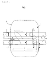
- Figure 1 is a diagram illustrating schematically a tread for a pneumatic tyre according to an embodiment of the present invention
- Figure 2 is an enlarged sectional view of the tread for a pneumatic tyre as viewed along line II-II in Figure 1
- Figure 3 is an enlarged sectional view of the tread for a pneumatic tyre as viewed along line III-III in Figure 1 .
- reference number 1 indicates a pneumatic tyre tread 1 according to the present embodiment
- two circumferential grooves 2 having a width W and extending in the circumferential direction of the tyre as indicated by XX' are formed in the tread 1, and ribs 3 demarcated by these circumferential grooves 2 are formed in the tread 1.
- the size of the tyre in this example is 225/55R16.
- the width W of the circumferential grooves 2 is 14.5mm.
- the installation interval P between groove fences 4 formed in the same circumferential groove 2 is provided in such a way that it is a shorter interval than the footprint length L, so that at least one groove fence is always present within the footprint 5 in each circumferential groove 2.
- the width l of the groove fences 4 is 13.5mm.
- the bottom portion 41 of the groove fence 4 is connected as shown in the diagrams to the bottom portion 21 of the circumferential groove 2, and as shown in Figure 3 , the groove fence 4 is provided in such a way that it extends in the radial direction of the tyre (the direction that is perpendicular to the axis of rotation of the tyre). Further, as shown in Figure 2 , side surface portions 42 on each side of the groove fence 4 are provided in such a way that there is a prescribed gap between the whole thereof, excluding the connecting portion (41) described above, and opposing walls 22 of the circumferential groove 4.
- each groove fence 4 is formed such that it extends in a direction perpendicular to the direction in which the circumferential grooves 2 extend.
- Each groove fence 4 has a rectangular cross-sectional shape, and the rectangular cross section has a width l as described above, and a thickness e (refer to Figure 3 ).
- the groove fence 4 as viewed in the longitudinal direction (front view) of the circumferential groove 2 is formed in the shape of a rectangle, and as shown in Figure 2 and Figure 3 it has a height h which is slightly lower than the depth D of the circumferential groove 2.
- the groove fence 4 is formed such that it blocks at least 70% of the cross-sectional area of the circumferential groove 2, and is formed such that it collapses under the water pressure of liquids such as principally water that flow within the circumferential groove 2.
- the depth D of the circumferential groove 2 is 8.0mm
- the height h of the groove fence 4 is 7.0mm
- the thickness e of the groove fence 4 is 0.6mm
- the groove fence 4 blocks approximately 87% of the cross-sectional area of the circumferential groove 2.
- the groove fence 4 should be of a rectangular shape having a height h of at least approximately 5.6mm such that it blocks at least 70% of the cross-sectional area of the circumferential groove 2. It should be noted that without limitation to the present mode of embodiment, if the width W and the depth D of the tyre circumferential groove 2 change, the height h of the groove fence 4 should be modified accordingly such that it blocks at least 70% of the cross-sectional area of the circumferential groove 2.
- the groove fences 4 consist of the same material as the ribs 3 of the tread 1 (the tread part). It should be noted that the groove fences 4 may consist of a different material to the ribs 3.
- the groove fences 4 are formed using a material which has a modulus at 10% elongation (M 10 ) of 5.8MPa.
- M 10 modulus at 10% elongation
- the bending parameter of the groove fence 4 prescribed (defined) by E • I h 3 ⁇ l is 304Pa.
- the value of this bending parameter 304Pa is a value such that the groove fence 4 does not collapse when only air is flowing through the circumferential groove 2 when being driven on a normal dry road surface, as a result of which the air column becomes shorter and air column resonance sound is reduced. It should be noted that the same effect is obtained if the value of the bending parameter is at least equal to 250Pa and at most equal to 350Pa.
- E is the modulus at 10% elongation (M 10 ) of the material used for the groove fence 4
- l is the width of the groove fence 4 projected onto a surface parallel to the axis of rotation of the tyre
- I is the second moment of area, defined from the abovementioned width l of the groove fence 4 and thickness e of the groove fence 4, as e 3 ⁇ l 12
- h is the height of the groove fence 4 in a direction perpendicular to the axis of rotation of the tyre.
- Figure 4 is an enlarged sectional view illustrating a state in which the tread for a pneumatic tyre as viewed along line II-II in Figure 1 is being driven on a wet road surface
- Figure 5 is an enlarged sectional view illustrating a state in which the tread for a pneumatic tyre as viewed along line III-III in Figure 1 is being driven on a wet road surface.
- the groove fence 4 having a bending parameter set to 304Pa as described above collapses or bends under the water pressure generated by liquids such as principally water flowing through the circumferential groove 2 when being driven on a wet road surface, and as a result its height is reduced to h*, the main part of the circumferential groove is released by virtue of the fact that the height is reduced, and drainage is ensured. It should be noted that the same effect is obtained if the value of the bending parameter is at least equal to 250Pa and at most equal to 350Pa.
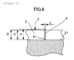
- Figure 6 is an enlarged sectional view of a state in which the tread for a pneumatic tyre as viewed along line III-III in Figure 1 has been worn down by approximately 30%.
- Figure 6 illustrates a state in which, after having been driven a prescribed distance, the depth D of the circumferential groove 2 has been worn down to a depth D' which is shallower than the original height h of the groove fence 4.
- the groove fence 4 having a bending parameter set to 304Pa as described above has worn down such that its distal end portion which is in contact with the road surface is oblique and its height has been reduced from its original height h to h' on the high side and h" on the low side, and the height h" on the low side is approximately the same height as the depth D' of the circumferential groove 2. It should be noted that the same effect is obtained if the value of the bending parameter is at least equal to 250Pa and at most equal to 350Pa.
- a groove fence 4 of which the bending parameter described above has been appropriately set (although it is 304Pa in the present mode of embodiment, the value of the bending parameter may be at least equal to 250Pa and at most equal to 350Pa.) does not collapse under the pressure of air when rolling while being driven on a dry road surface, and it also does not buckle. Further, although it falls slightly or bends due to reaction forces when it comes into contact with the road surface, an appropriate contact pressure is generated between the distal end portion of the groove fence 4 and the road surface, and it becomes worn through the generation of slippage within the tread footprint as a result of the rolling of the tyre. As a result, the groove fence 4 can be caused to wear to a degree equivalent to that of the tread portion.
- the shape of the groove fence 4 across the width l may be formed with an undulating shape such that it collapses under water pressure as described above and such that an appropriate contact pressure is generated against the road surface; or the surface of the groove fence 4 as viewed from the longitudinal direction (front view) of the circumferential groove 2 may for example be provided to some extent with an uneven portion which adjusts the degree to which the groove fence 4 can bend; or it may be formed as another shape such as a rectangular or trapezoidal shape with corners that are rounded when viewed from the front.
- the second moment of area may be calculated by approximation using the defining equation described above (e 3 l/12), using the average thickness e of the groove fence 4, or a suitable second moment of area defining equation appropriate to the cross-sectional shape according to the variation may be used.
- the specimen tyres according to the conventional example, the comparative example and embodiment 1 were in each case tyres of size 225/55R16, the wheel size was 7.0J x 16, and the pressure was set to 250kPa.
- Embodiment 1 Conventional example Comparative example Groove fences? Yes No Yes Groove fence thickness (mm) 0.6 - 0.6 Initial groove fence height (mm) 7.0 - 7.0 Modulus (M 10 ) of groove fence material (MPa) 5.8 5.8 1.3 Groove fence bending parameter (Pa) 304 - 68 Depth of remaining circumferential groove (mm) 5.5 5.5 5.5 Height of remaining groove fence (high side) (mm) 6.0 - 7.0 Height of remaining groove fence (low side) (mm) 5.5 - 6.5 Drainage performance (index) 100 100 100 100 Noise performance (dBA) 0.0 +2.0 0.0
Landscapes
- Engineering & Computer Science (AREA)
- Mechanical Engineering (AREA)
- Tires In General (AREA)
Abstract
Description
- The present invention relates to a tread for a pneumatic tyre, and in particular relates to a tread for a pneumatic tyre in which drainage performance can be maintained and air column resonance sound can be reduced by forming groove fences in circumferential grooves of the tread, while the groove fences can be caused to wear to a degree equivalent to that of the tread portion.
- Air column resonance sound in circumferential grooves formed in tyre treads is generated by means of resonance in a tube (air column) formed by the circumferential groove and the road surface, and the resonant frequency depends on the length of the air column formed between the circumferential groove and the road surface.
- This air column resonance sound manifests itself in the form of noise inside and outside the vehicle, and its peak is often at around 1kHz, which readily reaches the human ear. As a technique for reducing the air column resonance noise of circumferential grooves it is known to reduce the air column resonance noise by interrupting the flow of air in the direction in which the circumferential groove is formed, by providing so-called groove fences, in other words protrusions, which extend from the bottom or the walls of the circumferential groove, blocking all or most of the circumferential groove. However, interrupting the flow of air in the direction in which the circumferential groove is formed also interrupts the flow within the circumferential groove of water that penetrates into the circumferential groove when being driven on a wet road surface, and because there is a deterioration in the drainage of water interposed between the pneumatic tyre and the road surface, handling stability on wet road surfaces deteriorates.
-
Figure 4 of Patent literature article 1 discloses a technique aimed at achieving both drainage and a reduction in air column resonance sound by disposing within a circumferential groove three groove fences spaced apart from each other and extending respectively from the groove bottom and from opposing groove walls within the groove. - Also,
Figure 3 ofPatent literature article 2 discloses a technique aimed at achieving both drainage and a reduction in air column resonance sound by disposing groove fences, which extend from the bottom of a circumferential groove, in such a way that the greater part thereof from the opening of the circumferential groove does not touch the groove walls. - Patent literature article 1: Japanese Patent Kokai
1999-105511 2006-341655 - However, with the techniques disclosed in the abovementioned Patent literature article 1 and
Patent literature article 2, in order for the groove fences to function, the groove fences are thin in the circumferential direction of the tyre and deform readily, but there are problems in that depending on the material used groove fences which deform readily do not wear readily when being driven repeatedly, a difference arises between the amount of wear of the groove fence and that of the tread portion, and as a result the groove fence protrudes from the tread part and the groove fence hits the road surface generating an abnormal sound. Generation of such an abnormal sound contradicts the original role of the groove fence described above, namely to reduce noise by reducing the amount of air column resonance sound. There is also a problem in that by virtue of the fact that the groove fence protrudes from the tread portion, unintended parts of the groove fence come into contact with the ground and are subjected to wear, and the groove fence becomes damaged when being driven. - To this end, the present invention is intended to resolve the problems faced by the prior art described above, and its aim is to provide a pneumatic tyre in which groove fences can be caused to wear to a degree equivalent to that of the tread portion, while reducing the air column resonance sound and maintaining drainage performance.
- In order to achieve the abovementioned objective, the present invention is a tread for a pneumatic tyre having at least one circumferential groove having a bottom portion and opposing walls, at least two ribs adjacent to the circumferential groove, and a plurality of groove fences formed within the at least one circumferential groove such that the circumferential groove is interrupted, characterised in that the groove fences are formed extending from the bottom portion of the circumferential groove in a direction perpendicular to the axis of rotation of the tyre in such a way that there are gaps to the walls, and at least 70% of the cross-sectional area of the circumferential groove in which the abovementioned groove fences are formed is blocked, and in that the bending parameter of the groove fences, defined as

where E is the modulus at 10% elongation of the material used for the groove fences, I is the second moment of area of the groove fence, h is the height of the groove fence, and 1 is the width of the groove fence, is at least equal to 250Pa and at most equal to 350Pa. - In the present invention configured in this way, the groove fences which are formed extending in the radial direction of the tyre inside the circumferential groove from the bottom portion thereof and which block at least 70% of the cross-sectional area of the circumferential groove, alter, relative to a case in which groove fences are not formed, the length of an air column formed between the circumferential groove and the road surface, and it is straightforward to shift the peak of the air column resonance sound away from the frequency band which readily reaches the human ear, and as a result noise due to the air column resonance sound is improved.
- Further, in the present invention the configuration is such that the bending parameter of the groove fences, defined as E·I/(h3l) is at most equal to 350Pa, and thus the groove fences collapse under the pressure of water that has penetrated into the circumferential groove, and drainage of the circumferential groove can be ensured. In other words, if the bending parameter of the groove fences is larger than 350Pa then the groove fences become less liable to collapse under the pressure of water that has penetrated into the circumferential groove, and thus drainage performance deteriorates.
- Further, in the present invention the configuration is such that the bending parameter of the groove fences, defined as E·I/(h3l), is at least equal to 250Pa, and thus when a groove fence is in direct contact with the road surface while passing through the tread footprint when the tyre is rolling, it is possible to cause an appropriate contact pressure to be generated between the road surface and the groove fence without excessive bending occurring when the distal end portion of the groove fence comes into contact with the road surface and is subjected to a reaction force, and as a result the groove fence can be caused to wear to a degree equivalent to the amount of wear of the tread portion which has at least two ribs. In other words, if the bending parameter of the groove fences is smaller than 250Pa then the groove fences buckle under the reaction force when in contact with the road surface, an appropriate contact pressure cannot be generated between the road surface and the groove fence, and it is thus not possible to cause the groove fence to wear to a degree equivalent to that of the tread portion.
- Here, the bending parameter of the groove fences is defined as E·I(h3l). Here, E is the modulus at 10% elongation (M10) of the material used for the groove fences, l is the width of the groove fence projected onto a surface parallel to the axis of rotation of the tyre, and I is the second moment of area. The second moment of area I is defined as

for cases in which the abovementioned groove fence has a fixed width l in its height direction, and the groove fence has a fixed thickness e.
Further, h is the height of the groove fence in a direction perpendicular to the axis of rotation of the tyre. Thus the bending parameter of the groove fence: E·I/(h3l) is a compound function of the dimensions of the groove fence and the properties of the material used for the groove fence.
In developing a tread for a pneumatic tyre in which, as described hereinabove, the groove fence is caused to wear to a degree equivalent to that of the tread portion, while air column resonance sound is reduced and drainage performance is maintained, the inventors found this groove fence bending parameter
to be a parameter suitable for evaluating these effects (in particular drainage performance and groove fence wear performance), and found through analysis and experimentation that the effects described above could be obtained effectively if the parameter was within the range of values mentioned above (at least equal to 250Pa and at most equal to 350Pa). - Here, 'groove' refers to a space having a width and a depth and demarcated by two walls which under normal usage conditions do not come into contact with each other.
- Further, 'circumferential groove' refers to a groove which extends in the circumferential direction of the tyre, including not only straight grooves but also grooves which extend around the whole tyre in the circumferential direction in a zigzag or wave-like fashion.
- Further, 'tread footprint' refers to the surface region of the tread that is in contact with the road surface when the tyre is mounted on an applicable rim as defined in the industrial standards mentioned below, is inflated to its rated pressure and a rated load is applied.
- Further, 'standards' are defined by industrial standards that are valid in the region in which the tyre is manufactured or used. Examples of industrial standards are: in Europe, the ETRTO (The European Tyre and Rim Technical Organisation) "Standards Manual"; in the USA, the TRA (the Tire and Rim Association, Inc.) "Year Book"; and in Japan, the Japan Automobile Tyre Manufacturers Association (JATMA) "JATMA Year Book". Further, 'applicable rim' refers to a rim prescribed in these standards according to the size of the tyre, 'rated pressure' refers to the air pressure prescribed in these standards corresponding with the load-carrying capacity, and 'rated load' refers to the maximum mass with which the tyre is permitted to be loaded according to these standards.
- Further, the 'modulus of the material' in the present invention refers to the tensile stress (modulus) at 10% elongation (M10) obtained by a vulcanised rubber composition tensile test at 23°C measured in conformance with JISK6251, and in the present invention the tensile stress at 10% elongation in a test based on this JIS standard is used as the value 'E' mentioned above. For the test specimens, unvulcanised rubber composition is vulcanised for 40 minutes at 150°C and is punched out using a prescribed dumbbell-shaped or ring-shaped punch cutting die. The test specimens may be collected from vulcanised tyres. In this case the collected rubber composition is sliced into thin sections having a thickness of between 0.4mm and 10mm, and is punched out using a ring-shaped punch cutting die with an outer diameter in the range of 3mm to 10mm. The elongation of the test specimens is measured after the test specimens have been stress softened, and is computed by dividing the tensile force at 10% elongation by the initial cross-sectional area of the test specimen. The measurements are performed in conformance with JISK6250 and under conditions of standard temperature (23±2°C) and humidity (relative humidity 50±5%).
- In the present invention, the modulus at 10% elongation (M10) of the material used for the groove fences is preferably between 2.0Mpa and 8.0MPa. In the present invention configured in this way, drainage can be ensured and the groove fences can be caused to wear to approximately the same degree as the tread portion, while achieving a reduction in the air column resonance sound. In other words, if the modulus at 10% elongation (M10) of the material used for the groove fences is smaller than 2.0MPa, then there is an increased danger that the groove fences will buckle when in contact with the road surface, due to reduced material stiffness, and it thus becomes difficult to cause the groove fences to wear to approximately the same degree as the tread portion. On the other hand, if the modulus at 10% elongation (M10) of the material used for the groove fences is larger than 8.0MPa, then due to the higher material stiffness it becomes difficult to cause the groove fences to collapse under the pressure of water that has penetrated into the circumferential groove. Therefore, if the modulus at 10% elongation (M10) of the material used for the groove fences is set to between 2.0MPa and 8.0MPa, then drainage can be ensured and the groove fences can be caused to wear to a degree equivalent to that of the tread portion, while achieving a reduction in the air column resonance sound.
- In the present invention the thickness of the groove fences is preferably between 0.5mm and 0.7mm. In the present invention configured in this way, drainage can be ensured and the groove fences can be caused to wear to a degree equivalent to that of the tread portion, while achieving a reduction in the air column resonance sound. In other words, if the thickness of the groove fences is smaller than 0.5mm, then there is an increased danger that the groove fences will buckle when in contact with the road surface, due to reduced dimensional stiffness of the groove fences, and it thus becomes difficult to cause the groove fences to wear to approximately the same degree as the tread portion. On the other hand, if the thickness of the groove fences is larger than 0.7mm, then due to the higher dimensional stiffness of the groove fences it becomes difficult to cause the groove fences to collapse under the pressure of water that has penetrated into the circumferential groove. Therefore, if the thickness of the groove fences is set to between 0.5mm and 0.7mm, then drainage can be ensured and the groove fences can be caused to wear to a degree equivalent to that of the tread portion, while achieving a reduction in the air column resonance sound.
- In the present invention, the material used for the groove fences is preferably the same material as the tread part including the at least two ribs. In the present invention configured in this way, drainage can be ensured and the groove fences can be caused to wear to a degree equivalent to that of the tread portion while achieving a reduction in the air column resonance sound, without the use of a special process during manufacture, since a special material is not used for the groove fence portion.
- In the present invention, the material used for the groove fences is preferably a different material to the tread part including the at least two ribs. In the present invention configured in this way, drainage can be ensured and the groove fences can be caused to wear to a degree equivalent to that of the tread portion while achieving a reduction in the air column resonance sound, even if a special material is used for the tread portion, which is critical to the performance when in contact with the ground, since it is possible to use for the groove fence portion an appropriate material adapted to the dimensions thereof.
- In the present invention the cross-sectional shape of the groove fences is preferably rectangular.
In the present invention configured in this way, an effective groove fence bending efficiency can be obtained since the cross-sectional shape of the groove fences is rectangular, and as a result drainage can be ensured more reliably and the groove fences can be caused to wear to a degree equivalent to that of the tread portion while achieving a reduction in the air column resonance sound. - When the pneumatic tyre tread according to the present invention is employed, the groove fences can be caused to wear to a degree equivalent to that of the tread portion, while the air column resonance sound is reduced and drainage performance is maintained.
-
- [
Figure 1 ] is a diagram illustrating schematically a tread for a pneumatic tyre according to an embodiment of the present invention. - [
Figure 2 ] is an enlarged sectional view of the tread for a pneumatic tyre as viewed along line II-II inFigure 1 . - [
Figure 3 ] is an enlarged sectional view of the tread for a pneumatic tyre as viewed along line III-III inFigure 1 . - [
Figure 4 ] is a diagram which illustrates, similarly toFigure 2 , an enlarged sectional view of the tread for a pneumatic tyre as viewed along line II-II inFigure 1 , illustrating schematically a state in which the tyre is being driven on a wet road surface. - [
Figure 5 ] is a diagram which illustrates, similarly toFigure 3 , an enlarged sectional view of the tread for a pneumatic tyre as viewed along line III-III inFigure 1 , illustrating schematically a state in which the tyre is being driven on a wet road surface. - [
Figure 6 ] is a diagram which illustrates, similarly toFigure 3 , an enlarged sectional view of the tread for a pneumatic tyre as viewed along line III-III inFigure 1 , illustrating schematically a state in which the tread portion has been worn down by approximately 30%. - A preferred mode of embodiment of the present invention will now be described with reference to the diagrams.
First, a tread for a pneumatic tyre according to a mode of embodiment of the present invention will be described based onFigure 1 to Figure 3 .Figure 1 is a diagram illustrating schematically a tread for a pneumatic tyre according to an embodiment of the present invention,Figure 2 is an enlarged sectional view of the tread for a pneumatic tyre as viewed along line II-II inFigure 1 , andFigure 3 is an enlarged sectional view of the tread for a pneumatic tyre as viewed along line III-III inFigure 1 .
First, as shown inFigure 1 , reference number 1 indicates a pneumatic tyre tread 1 according to the present embodiment, twocircumferential grooves 2 having a width W and extending in the circumferential direction of the tyre as indicated by XX' are formed in the tread 1, andribs 3 demarcated by thesecircumferential grooves 2 are formed in the tread 1. It should be noted that the size of the tyre in this example is 225/55R16. In the present mode of embodiment, the width W of thecircumferential grooves 2 is 14.5mm.
On the diagram are shown thetread footprint 5 and the tread footprint length L when the tyre is inflated to its rated pressure and a rated load is applied. It should be noted that according to the 'ETRTO Standard Manual 2010' the applicable rim for this size is 7J, the rated pressure is 250kPa, and the rated load is 690kg, and in the present embodiment the footprint length L is 143mm. - When the tyre is rolling, air columns are formed between the road surface and each of the
circumferential grooves 2 which pass through thetread footprint 5, and since the resonant frequency of thecircumferential grooves 2 depends on the length of the air column formed in this way, in order to vary the frequency of the air column resonance sound the length of the air column should be varied.
As shown inFigure 1 , a plurality ofgroove fences 4 of width l, with which thecircumferential grooves 2 can be largely blocked, are formed in eachcircumferential groove 2 for the purpose of varying the length of the air column. The installation interval P betweengroove fences 4 formed in the samecircumferential groove 2 is provided in such a way that it is a shorter interval than the footprint length L, so that at least one groove fence is always present within thefootprint 5 in eachcircumferential groove 2. In the present mode of embodiment, the width l of thegroove fences 4 is 13.5mm. - Next, as shown in
Figure 2 and Figure 3 , thebottom portion 41 of thegroove fence 4 is connected as shown in the diagrams to thebottom portion 21 of thecircumferential groove 2, and as shown inFigure 3 , thegroove fence 4 is provided in such a way that it extends in the radial direction of the tyre (the direction that is perpendicular to the axis of rotation of the tyre). Further, as shown inFigure 2 ,side surface portions 42 on each side of thegroove fence 4 are provided in such a way that there is a prescribed gap between the whole thereof, excluding the connecting portion (41) described above, and opposingwalls 22 of thecircumferential groove 4. - As shown in
Figure 1 , eachgroove fence 4 is formed such that it extends in a direction perpendicular to the direction in which thecircumferential grooves 2 extend. Eachgroove fence 4 has a rectangular cross-sectional shape, and the rectangular cross section has a width l as described above, and a thickness e (refer toFigure 3 ).
Further, as shown inFigure 2 , thegroove fence 4 as viewed in the longitudinal direction (front
view) of thecircumferential groove 2 is formed in the shape of a rectangle, and as shown inFigure 2 and Figure 3 it has a height h which is slightly lower than the depth D of thecircumferential groove 2. - The
groove fence 4 is formed such that it blocks at least 70% of the cross-sectional area of thecircumferential groove 2, and is formed such that it collapses under the water pressure of liquids such as principally water that flow within thecircumferential groove 2. In the present mode of embodiment, the depth D of thecircumferential groove 2 is 8.0mm, the height h of thegroove fence 4 is 7.0mm, the thickness e of thegroove fence 4 is 0.6mm, and thegroove fence 4 blocks approximately 87% of the cross-sectional area of thecircumferential groove 2. It should be noted that for example in the case of the tyre in the present mode of embodiment thegroove fence 4 should be of a rectangular shape having a height h of at least approximately 5.6mm such that it blocks at least 70% of the cross-sectional area of thecircumferential groove 2. It should be noted that without limitation to the present mode of embodiment, if the width W and the depth D of the tyrecircumferential groove 2 change, the height h of thegroove fence 4 should be modified accordingly such that it blocks at least 70% of the cross-sectional area of thecircumferential groove 2. - In the present mode of embodiment, the
groove fences 4 consist of the same material as theribs 3 of the tread 1 (the tread part). It should be noted that thegroove fences 4 may consist of a different material to theribs 3. - Further, in the present mode of embodiment the
groove fences 4 are formed using a material which has a modulus at 10% elongation (M10) of 5.8MPa. Thus in the present invention the bending parameter of thegroove fence 4, prescribed (defined) by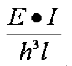
is 304Pa. The value of this bending parameter 304Pa is a value such that thegroove fence 4 does not collapse when only air is flowing through thecircumferential groove 2 when being driven on a normal dry road surface, as a result of which the air column becomes shorter and air column resonance sound is reduced. It should be noted that the same effect is obtained if the value of the bending parameter is at least equal to 250Pa and at most equal to 350Pa.
Here, E is the modulus at 10% elongation (M10) of the material used for thegroove fence 4, l is the width of thegroove fence 4 projected onto a surface parallel to the axis of rotation of the tyre, I is the second moment of area, defined from the abovementioned width l of thegroove fence 4 and thickness e of thegroove fence 4, as
and h is the height of thegroove fence 4 in a direction perpendicular to the axis of rotation of the tyre. - Next, the condition when a tread for a pneumatic tyre according to a mode of embodiment of the present invention is being driven on a wet road surface will be described with reference to
Figure 4 and Figure 5 .
Figure 4 is an enlarged sectional view illustrating a state in which the tread for a pneumatic tyre as viewed along line II-II inFigure 1 is being driven on a wet road surface, andFigure 5 is an enlarged sectional view illustrating a state in which the tread for a pneumatic tyre as viewed along line III-III inFigure 1 is being driven on a wet road surface. - As shown in
Figure 4 and Figure 5 , thegroove fence 4 having a bending parameter set to 304Pa as described above collapses or bends under the water pressure generated by liquids such as principally water flowing through thecircumferential groove 2 when being driven on a wet road surface, and as a result its height is reduced to h*, the main part of the circumferential groove is released by virtue of the fact that the height is reduced, and drainage is ensured. It should be noted that the same effect is obtained if the value of the bending parameter is at least equal to 250Pa and at most equal to 350Pa. - Next, the state after the tread has become worn, in a tread for a pneumatic tyre according to a mode of embodiment of the present invention, will now be described with reference to
figure 6 .
Figure 6 is an enlarged sectional view of a state in which the tread for a pneumatic tyre as viewed along line III-III inFigure 1 has been worn down by approximately 30%.
Figure 6 illustrates a state in which, after having been driven a prescribed distance, the depth D of thecircumferential groove 2 has been worn down to a depth D' which is shallower than the original height h of thegroove fence 4.
After having been driven a prescribed distance, thegroove fence 4 having a bending parameter set to 304Pa as described above has worn down such that its distal end portion which is in contact with the road surface is oblique and its height has been reduced from its original height h to h' on the high side and h" on the low side, and the height h" on the low side is approximately the same height as the depth D' of thecircumferential groove 2. It should be noted that the same effect is obtained if the value of the bending parameter is at least equal to 250Pa and at most equal to 350Pa. - A
groove fence 4 of which the bending parameter described above has been appropriately set (although it is 304Pa in the present mode of embodiment, the value of the bending parameter may be at least equal to 250Pa and at most equal to 350Pa.) does not collapse under the pressure of air when rolling while being driven on a dry road surface, and it also does not buckle. Further, although it falls slightly or bends due to reaction forces when it comes into contact with the road surface, an appropriate contact pressure is generated between the distal end portion of thegroove fence 4 and the road surface, and it becomes worn through the generation of slippage within the tread footprint as a result of the rolling of the tyre. As a result, thegroove fence 4 can be caused to wear to a degree equivalent to that of the tread portion. - It should be noted that as variations of the present mode of embodiment, provided that it has the effect described above, the shape of the
groove fence 4 across the width l (the cross-sectional shape) may be formed with an undulating shape such that it collapses under water pressure as described above and such that an appropriate contact pressure is generated against the road surface; or the surface of thegroove fence 4 as viewed from the longitudinal direction (front view) of thecircumferential groove 2 may for example be provided to some extent with an uneven portion which adjusts the degree to which thegroove fence 4 can bend; or it may be formed as another shape such as a rectangular or trapezoidal shape with corners that are rounded when viewed from the front.
In such cases, if for example a wave-shaped or protruding body is provided as described above then the second moment of area may be calculated by approximation using the defining equation described above (e3l/12), using the average thickness e of thegroove fence 4, or a suitable second moment of area defining equation appropriate to the cross-sectional shape according to the variation may be used. - A particularly preferred mode of embodiment of the present invention has been described hereinabove, but the present invention may be modified and implemented in the form of various embodiments without limitation to the mode of embodiment shown in the diagrams.
- Next, in order to clarify the advantages of the present invention, an explanation will be given of the results of tests performed using a conventional example in which groove fences are not provided, a comparative example provided with groove fences, and a pneumatic tyre according to embodiment 1 of the present invention.
- The specimen tyres according to the conventional example, the comparative example and embodiment 1 were in each case tyres of size 225/55R16, the wheel size was 7.0J x 16, and the pressure was set to 250kPa.
-
- (1) Wear performance:
Unused specimen tyres were mounted, using the rims and at the pressure mentioned above, onto the four wheels of three identical vehicles (2000cc displacement FR cars) which were driven in a three-vehicle convoy approximately 7,000km on a prescribed asphalt test course with one driver in each vehicle, and the depths of the remaining grooves and the heights of the remaining groove fences were measured. - (2) Drainage performance:
Unused specimen tyres were mounted, using the rims and at the pressure mentioned above, onto the four wheels of vehicles (4300cc displacement FR cars) which were driven, with one driver in each vehicle, on a straight-line course comprising an asphalt road surface provided with a pool of water of depth approximately 10mm, and the driving speed at which the driver in the vehicle felt that the tyres were hydroplaning is presented as an index, where 100 corresponds to the conventional example. A larger index indicates a more satisfactory performance. - (3) Noise performance:
Unused specimen tyres were caused to rotate, using the rims and at the pressure mentioned above, at a speed of 60km/h on a rotating drum of diameter 2.7m installed in an anechoic chamber, and the noise level was measured using a microphone installed in the vicinity of the point at which the tyre entered the tread footprint. The measured noise is presented as the difference in sound pressure level compared with the conventional example, for the sound pressure level of the frequency band from 0 to 2,000Hz to which an A filter has been applied. A smaller value indicates a more satisfactory performance. -
[Table 1] Embodiment 1 Conventional example Comparative example Groove fences? Yes No Yes Groove fence thickness (mm) 0.6 - 0.6 Initial groove fence height (mm) 7.0 - 7.0 Modulus (M10) of groove fence material (MPa) 5.8 5.8 1.3 Groove fence bending parameter (Pa) 304 - 68 Depth of remaining circumferential groove (mm) 5.5 5.5 5.5 Height of remaining groove fence (high side) (mm) 6.0 - 7.0 Height of remaining groove fence (low side) (mm) 5.5 - 6.5 Drainage performance (index) 100 100 100 Noise performance (dBA) 0.0 +2.0 0.0 - As shown in Table 1, it can be confirmed that the groove fences in the product according to the embodiment are subjected to an equivalent degree of wear to the wear of the tread portion, while noise performance and drainage performance are maintained.
-
- 1
- Pneumatic tyre tread
- 2
- Circumferential groove
- 21
- Bottom portion of
circumferential groove 2 - 22
- Opposing walls of
circumferential groove 4 - 3
- Rib
- 4
- Groove fence
- 41
- Bottom portion of groove fence 4 (portion connected to
bottom portion 21 of circumferential groove 2) - 42
- Side surface portions on either side of
groove fence 4 - 5
- Tread footprint
Claims (6)
- Tread for a pneumatic tyre having at least one circumferential groove having a bottom portion and opposing walls, at least two ribs adjacent to the circumferential groove, and a plurality of groove fences formed within the abovementioned at least one circumferential groove such that the abovementioned circumferential groove is interrupted, characterised in that the abovementioned groove fences are formed extending from the bottom portion of the abovementioned circumferential groove in a direction perpendicular to the axis of rotation of the tyre in such a way that there are gaps to the abovementioned walls, and at least 70% of the cross-sectional area of the abovementioned circumferential groove in which the abovementioned groove fences are formed is blocked, and in that the bending parameter of the groove fences which extend from the bottom portion of the abovementioned circumferential groove in a direction perpendicular to the axis of rotation of the tyre, defined as

where E is the modulus at 10% elongation of the material used for the abovementioned groove fences, I is the second moment of area of the abovementioned groove fence, h is the height of the abovementioned groove fence, and l is the width of the abovementioned groove fence, is at least equal to 250Pa and at most equal to 350Pa. - Tread for a pneumatic tyre according to
Claim 1, characterised in that the modulus at 10% elongation (M10) of the material used for the abovementioned groove fences is at least equal to 2.0MPa and at most equal to 8.0MPa. - Tread for a pneumatic tyre according to
Claim 1 or Claim 2, characterised in that the thickness of the abovementioned groove fences is at least equal to 0.5mm and at most equal to 0.7mm. - Tread for a pneumatic tyre according to any
one of Claims 1 to 3, characterised in that the material used for the abovementioned groove fences is the same material as the material of the tread part including the abovementioned at least two ribs. - Tread for a pneumatic tyre according to any
one of Claims 1 to 3, characterised in that the material used for the abovementioned groove fences is a different material to the material of the tread part including the abovementioned at least two ribs. - Tread for a pneumatic tyre according to any
one of Claims 1 to 5, characterised in that the cross-sectional shape of the abovementioned groove fences is rectangular.
Applications Claiming Priority (1)
| Application Number | Priority Date | Filing Date | Title |
|---|---|---|---|
| PCT/JP2010/068180 WO2012049772A1 (en) | 2010-10-15 | 2010-10-15 | Pneumatic tire tread |
Publications (3)
| Publication Number | Publication Date |
|---|---|
| EP2628613A1 true EP2628613A1 (en) | 2013-08-21 |
| EP2628613A4 EP2628613A4 (en) | 2017-04-05 |
| EP2628613B1 EP2628613B1 (en) | 2018-07-11 |
Family
ID=45938020
Family Applications (1)
| Application Number | Title | Priority Date | Filing Date |
|---|---|---|---|
| EP10858418.6A Active EP2628613B1 (en) | 2010-10-15 | 2010-10-15 | Pneumatic tire tread |
Country Status (7)
| Country | Link |
|---|---|
| US (1) | US9597930B2 (en) |
| EP (1) | EP2628613B1 (en) |
| JP (1) | JP5728018B2 (en) |
| CN (1) | CN103209841B (en) |
| BR (1) | BR112013008396A8 (en) |
| RU (1) | RU2515621C1 (en) |
| WO (1) | WO2012049772A1 (en) |
Cited By (5)
| Publication number | Priority date | Publication date | Assignee | Title |
|---|---|---|---|---|
| EP2727748A4 (en) * | 2011-06-30 | 2015-04-15 | Michelin & Cie | TIRE TREAD TIRE |
| EP2727747A4 (en) * | 2011-06-30 | 2015-04-22 | Michelin & Cie | TIRE TREAD TIRE |
| EP2727745A4 (en) * | 2011-06-30 | 2015-04-29 | Michelin & Cie | TIRE TREAD TIRE |
| US9296261B2 (en) | 2011-06-30 | 2016-03-29 | Compagnie Generale Des Etablissements Michelin | Pneumatic tire tread |
| EP3086959A4 (en) * | 2013-12-26 | 2017-08-16 | Bridgestone Americas Tire Operations, LLC | Tire tread having a flexible gate apparatus |
Families Citing this family (3)
| Publication number | Priority date | Publication date | Assignee | Title |
|---|---|---|---|---|
| WO2017209159A1 (en) * | 2016-05-31 | 2017-12-07 | Compagnie Generale Des Etablissements Michelin | A noise reducing tread |
| US10518590B2 (en) * | 2018-03-05 | 2019-12-31 | Sensata Technologies, Inc. | System and method for tracking tire tread wear |
| KR102373832B1 (en) * | 2020-07-22 | 2022-03-14 | 엘지전자 주식회사 | Robot Cleaner |
Family Cites Families (14)
| Publication number | Priority date | Publication date | Assignee | Title |
|---|---|---|---|---|
| JPH03276802A (en) | 1990-03-05 | 1991-12-09 | Bridgestone Corp | Pneumatic tire |
| JP3815758B2 (en) | 1997-10-06 | 2006-08-30 | 株式会社ブリヂストン | Heavy duty pneumatic tire |
| JPH11217007A (en) * | 1998-02-03 | 1999-08-10 | Yokohama Rubber Co Ltd:The | Pneumatic tire |
| JP2002002223A (en) * | 2000-06-21 | 2002-01-08 | Yokohama Rubber Co Ltd:The | Pneumatic tire |
| US7004216B2 (en) * | 2003-12-11 | 2006-02-28 | The Goodyear Tire & Rubber Company | Tire tread including spaced projections in base of groove |
| JP4639974B2 (en) * | 2005-06-07 | 2011-02-23 | 横浜ゴム株式会社 | Pneumatic tire |
| JP2007290538A (en) * | 2006-04-25 | 2007-11-08 | Bridgestone Corp | Pneumatic tire for motorcycle |
| US7980281B2 (en) * | 2006-10-02 | 2011-07-19 | Toyo Tire & Rubber Co., Ltd. | Pneumatic tire with tread having protruding stripe in groove bottom and tire mold for making the tire |
| JP5148102B2 (en) * | 2006-11-24 | 2013-02-20 | 東洋ゴム工業株式会社 | Pneumatic tire |
| JP5211823B2 (en) * | 2008-04-21 | 2013-06-12 | 横浜ゴム株式会社 | Pneumatic tire with tread pattern |
| JP2010052698A (en) * | 2008-08-29 | 2010-03-11 | Bridgestone Corp | Tire |
| JP2010052699A (en) * | 2008-08-29 | 2010-03-11 | Bridgestone Corp | Tire |
| FR2939365B1 (en) * | 2008-12-05 | 2012-03-16 | Michelin Soc Tech | NOISE ATTENUATING DEVICE FOR ROLLING BAND. |
| FR2955289B1 (en) * | 2010-01-19 | 2012-01-27 | Soc Tech Michelin | TIRE TREAD COMPRISING AN IMPROVED NOISE REDUCING DEVICE |
-
2010
- 2010-10-15 WO PCT/JP2010/068180 patent/WO2012049772A1/en not_active Ceased
- 2010-10-15 EP EP10858418.6A patent/EP2628613B1/en active Active
- 2010-10-15 CN CN201080069598.XA patent/CN103209841B/en active Active
- 2010-10-15 RU RU2013122130/11A patent/RU2515621C1/en not_active IP Right Cessation
- 2010-10-15 BR BR112013008396A patent/BR112013008396A8/en not_active Application Discontinuation
- 2010-10-15 US US13/879,306 patent/US9597930B2/en active Active
- 2010-10-15 JP JP2012538541A patent/JP5728018B2/en active Active
Cited By (8)
| Publication number | Priority date | Publication date | Assignee | Title |
|---|---|---|---|---|
| EP2727748A4 (en) * | 2011-06-30 | 2015-04-15 | Michelin & Cie | TIRE TREAD TIRE |
| EP2727747A4 (en) * | 2011-06-30 | 2015-04-22 | Michelin & Cie | TIRE TREAD TIRE |
| EP2727745A4 (en) * | 2011-06-30 | 2015-04-29 | Michelin & Cie | TIRE TREAD TIRE |
| US9205707B2 (en) | 2011-06-30 | 2015-12-08 | Compagnie Generale Des Etablissements Michelin | Pneumatic tire tread |
| US9205708B2 (en) | 2011-06-30 | 2015-12-08 | Compagnie Generale Des Etablissements Michelin | Pneumatic tire tread |
| US9296261B2 (en) | 2011-06-30 | 2016-03-29 | Compagnie Generale Des Etablissements Michelin | Pneumatic tire tread |
| EP3086959A4 (en) * | 2013-12-26 | 2017-08-16 | Bridgestone Americas Tire Operations, LLC | Tire tread having a flexible gate apparatus |
| US10926586B2 (en) | 2013-12-26 | 2021-02-23 | Bridgestone Americas Tire Operations, Llc | Tire tread having a flexible gate apparatus |
Also Published As
| Publication number | Publication date |
|---|---|
| JP5728018B2 (en) | 2015-06-03 |
| BR112013008396A8 (en) | 2018-01-02 |
| JPWO2012049772A1 (en) | 2014-02-24 |
| US9597930B2 (en) | 2017-03-21 |
| US20140007997A1 (en) | 2014-01-09 |
| WO2012049772A1 (en) | 2012-04-19 |
| EP2628613B1 (en) | 2018-07-11 |
| CN103209841B (en) | 2015-10-21 |
| EP2628613A4 (en) | 2017-04-05 |
| CN103209841A (en) | 2013-07-17 |
| RU2515621C1 (en) | 2014-05-20 |
| BR112013008396A2 (en) | 2016-06-21 |
Similar Documents
| Publication | Publication Date | Title |
|---|---|---|
| EP2628613B1 (en) | Pneumatic tire tread | |
| EP1892127B1 (en) | Pneumatic tire | |
| EP2011671B1 (en) | Pneumatic tire | |
| CN108136853B (en) | Pneumatic tire | |
| EP3205516B1 (en) | Pneumatic tire | |
| KR950008772B1 (en) | Heavy Duty Air Tires Prevent Uneven Wear | |
| EP2614966B1 (en) | Heavy duty pneumatic tire | |
| EP2769853B1 (en) | Pneumatic tire | |
| RU2663262C1 (en) | Pneumatic tyre | |
| EP2586627B1 (en) | Pneumatic tire | |
| EP3269567B1 (en) | Tire | |
| EP3501852B1 (en) | Tyre | |
| EP2127910B1 (en) | Pneumatic tire | |
| EP3885162B1 (en) | Tire | |
| JP2010023728A (en) | Tire and its manufacturing method | |
| EP3466726A1 (en) | Tire | |
| EP3393826B1 (en) | A noise reducing tread | |
| EP3501850B1 (en) | Tire | |
| EP4265442B1 (en) | TIRE | |
| JP4925660B2 (en) | tire | |
| CN109311352B (en) | Noise reducing tread | |
| JP5437851B2 (en) | Pneumatic tire | |
| JP2020117150A (en) | tire | |
| JP5039376B2 (en) | Pneumatic tire | |
| JP5489661B2 (en) | Pneumatic tire |
Legal Events
| Date | Code | Title | Description |
|---|---|---|---|
| PUAI | Public reference made under article 153(3) epc to a published international application that has entered the european phase |
Free format text: ORIGINAL CODE: 0009012 |
|
| 17P | Request for examination filed |
Effective date: 20130515 |
|
| AK | Designated contracting states |
Kind code of ref document: A1 Designated state(s): AL AT BE BG CH CY CZ DE DK EE ES FI FR GB GR HR HU IE IS IT LI LT LU LV MC MK MT NL NO PL PT RO RS SE SI SK SM TR |
|
| DAX | Request for extension of the european patent (deleted) | ||
| RA4 | Supplementary search report drawn up and despatched (corrected) |
Effective date: 20170308 |
|
| RIC1 | Information provided on ipc code assigned before grant |
Ipc: B60C 11/04 20060101AFI20170302BHEP Ipc: B60C 11/13 20060101ALI20170302BHEP |
|
| RAP1 | Party data changed (applicant data changed or rights of an application transferred) |
Owner name: COMPAGNIE GENERALE DES ETABLISSEMENTS MICHELIN |
|
| RAP1 | Party data changed (applicant data changed or rights of an application transferred) |
Owner name: COMPAGNIE GENERALE DES ETABLISSEMENTS MICHELIN |
|
| GRAP | Despatch of communication of intention to grant a patent |
Free format text: ORIGINAL CODE: EPIDOSNIGR1 |
|
| RIC1 | Information provided on ipc code assigned before grant |
Ipc: B60C 19/00 20060101ALI20180306BHEP Ipc: B60C 11/13 20060101ALI20180306BHEP Ipc: B60C 11/04 20060101AFI20180306BHEP |
|
| INTG | Intention to grant announced |
Effective date: 20180409 |
|
| RIN1 | Information on inventor provided before grant (corrected) |
Inventor name: DAUTREY, NICOLAS Inventor name: SHIMANAKA, NANAE Inventor name: FUTAMURA, YASUHIKO Inventor name: ROTY, GAEL Inventor name: KANNO, YUJI Inventor name: GREVERIE, LUDOVIC |
|
| GRAS | Grant fee paid |
Free format text: ORIGINAL CODE: EPIDOSNIGR3 |
|
| GRAA | (expected) grant |
Free format text: ORIGINAL CODE: 0009210 |
|
| AK | Designated contracting states |
Kind code of ref document: B1 Designated state(s): AL AT BE BG CH CY CZ DE DK EE ES FI FR GB GR HR HU IE IS IT LI LT LU LV MC MK MT NL NO PL PT RO RS SE SI SK SM TR |
|
| REG | Reference to a national code |
Ref country code: GB Ref legal event code: FG4D |
|
| REG | Reference to a national code |
Ref country code: CH Ref legal event code: EP |
|
| REG | Reference to a national code |
Ref country code: AT Ref legal event code: REF Ref document number: 1016482 Country of ref document: AT Kind code of ref document: T Effective date: 20180715 |
|
| REG | Reference to a national code |
Ref country code: DE Ref legal event code: R096 Ref document number: 602010051928 Country of ref document: DE |
|
| REG | Reference to a national code |
Ref country code: IE Ref legal event code: FG4D |
|
| REG | Reference to a national code |
Ref country code: NL Ref legal event code: FP |
|
| REG | Reference to a national code |
Ref country code: FR Ref legal event code: PLFP Year of fee payment: 9 |
|
| RAP2 | Party data changed (patent owner data changed or rights of a patent transferred) |
Owner name: COMPAGNIE GENERALE DES ETABLISSEMENTS MICHELIN |
|
| REG | Reference to a national code |
Ref country code: LT Ref legal event code: MG4D |
|
| REG | Reference to a national code |
Ref country code: AT Ref legal event code: MK05 Ref document number: 1016482 Country of ref document: AT Kind code of ref document: T Effective date: 20180711 |
|
| PGFP | Annual fee paid to national office [announced via postgrant information from national office to epo] |
Ref country code: NL Payment date: 20181019 Year of fee payment: 9 |
|
| PG25 | Lapsed in a contracting state [announced via postgrant information from national office to epo] |
Ref country code: BG Free format text: LAPSE BECAUSE OF FAILURE TO SUBMIT A TRANSLATION OF THE DESCRIPTION OR TO PAY THE FEE WITHIN THE PRESCRIBED TIME-LIMIT Effective date: 20181011 Ref country code: AT Free format text: LAPSE BECAUSE OF FAILURE TO SUBMIT A TRANSLATION OF THE DESCRIPTION OR TO PAY THE FEE WITHIN THE PRESCRIBED TIME-LIMIT Effective date: 20180711 Ref country code: SE Free format text: LAPSE BECAUSE OF FAILURE TO SUBMIT A TRANSLATION OF THE DESCRIPTION OR TO PAY THE FEE WITHIN THE PRESCRIBED TIME-LIMIT Effective date: 20180711 Ref country code: LT Free format text: LAPSE BECAUSE OF FAILURE TO SUBMIT A TRANSLATION OF THE DESCRIPTION OR TO PAY THE FEE WITHIN THE PRESCRIBED TIME-LIMIT Effective date: 20180711 Ref country code: PL Free format text: LAPSE BECAUSE OF FAILURE TO SUBMIT A TRANSLATION OF THE DESCRIPTION OR TO PAY THE FEE WITHIN THE PRESCRIBED TIME-LIMIT Effective date: 20180711 Ref country code: FI Free format text: LAPSE BECAUSE OF FAILURE TO SUBMIT A TRANSLATION OF THE DESCRIPTION OR TO PAY THE FEE WITHIN THE PRESCRIBED TIME-LIMIT Effective date: 20180711 Ref country code: RS Free format text: LAPSE BECAUSE OF FAILURE TO SUBMIT A TRANSLATION OF THE DESCRIPTION OR TO PAY THE FEE WITHIN THE PRESCRIBED TIME-LIMIT Effective date: 20180711 Ref country code: IS Free format text: LAPSE BECAUSE OF FAILURE TO SUBMIT A TRANSLATION OF THE DESCRIPTION OR TO PAY THE FEE WITHIN THE PRESCRIBED TIME-LIMIT Effective date: 20181111 Ref country code: GR Free format text: LAPSE BECAUSE OF FAILURE TO SUBMIT A TRANSLATION OF THE DESCRIPTION OR TO PAY THE FEE WITHIN THE PRESCRIBED TIME-LIMIT Effective date: 20181012 Ref country code: NO Free format text: LAPSE BECAUSE OF FAILURE TO SUBMIT A TRANSLATION OF THE DESCRIPTION OR TO PAY THE FEE WITHIN THE PRESCRIBED TIME-LIMIT Effective date: 20181011 |
|
| PG25 | Lapsed in a contracting state [announced via postgrant information from national office to epo] |
Ref country code: ES Free format text: LAPSE BECAUSE OF FAILURE TO SUBMIT A TRANSLATION OF THE DESCRIPTION OR TO PAY THE FEE WITHIN THE PRESCRIBED TIME-LIMIT Effective date: 20180711 Ref country code: LV Free format text: LAPSE BECAUSE OF FAILURE TO SUBMIT A TRANSLATION OF THE DESCRIPTION OR TO PAY THE FEE WITHIN THE PRESCRIBED TIME-LIMIT Effective date: 20180711 Ref country code: HR Free format text: LAPSE BECAUSE OF FAILURE TO SUBMIT A TRANSLATION OF THE DESCRIPTION OR TO PAY THE FEE WITHIN THE PRESCRIBED TIME-LIMIT Effective date: 20180711 Ref country code: AL Free format text: LAPSE BECAUSE OF FAILURE TO SUBMIT A TRANSLATION OF THE DESCRIPTION OR TO PAY THE FEE WITHIN THE PRESCRIBED TIME-LIMIT Effective date: 20180711 |
|
| REG | Reference to a national code |
Ref country code: DE Ref legal event code: R097 Ref document number: 602010051928 Country of ref document: DE |
|
| PG25 | Lapsed in a contracting state [announced via postgrant information from national office to epo] |
Ref country code: RO Free format text: LAPSE BECAUSE OF FAILURE TO SUBMIT A TRANSLATION OF THE DESCRIPTION OR TO PAY THE FEE WITHIN THE PRESCRIBED TIME-LIMIT Effective date: 20180711 Ref country code: CZ Free format text: LAPSE BECAUSE OF FAILURE TO SUBMIT A TRANSLATION OF THE DESCRIPTION OR TO PAY THE FEE WITHIN THE PRESCRIBED TIME-LIMIT Effective date: 20180711 Ref country code: IT Free format text: LAPSE BECAUSE OF FAILURE TO SUBMIT A TRANSLATION OF THE DESCRIPTION OR TO PAY THE FEE WITHIN THE PRESCRIBED TIME-LIMIT Effective date: 20180711 Ref country code: EE Free format text: LAPSE BECAUSE OF FAILURE TO SUBMIT A TRANSLATION OF THE DESCRIPTION OR TO PAY THE FEE WITHIN THE PRESCRIBED TIME-LIMIT Effective date: 20180711 |
|
| PLBE | No opposition filed within time limit |
Free format text: ORIGINAL CODE: 0009261 |
|
| STAA | Information on the status of an ep patent application or granted ep patent |
Free format text: STATUS: NO OPPOSITION FILED WITHIN TIME LIMIT |
|
| PG25 | Lapsed in a contracting state [announced via postgrant information from national office to epo] |
Ref country code: SK Free format text: LAPSE BECAUSE OF FAILURE TO SUBMIT A TRANSLATION OF THE DESCRIPTION OR TO PAY THE FEE WITHIN THE PRESCRIBED TIME-LIMIT Effective date: 20180711 Ref country code: DK Free format text: LAPSE BECAUSE OF FAILURE TO SUBMIT A TRANSLATION OF THE DESCRIPTION OR TO PAY THE FEE WITHIN THE PRESCRIBED TIME-LIMIT Effective date: 20180711 Ref country code: SM Free format text: LAPSE BECAUSE OF FAILURE TO SUBMIT A TRANSLATION OF THE DESCRIPTION OR TO PAY THE FEE WITHIN THE PRESCRIBED TIME-LIMIT Effective date: 20180711 |
|
| REG | Reference to a national code |
Ref country code: CH Ref legal event code: PL |
|
| 26N | No opposition filed |
Effective date: 20190412 |
|
| GBPC | Gb: european patent ceased through non-payment of renewal fee |
Effective date: 20181015 |
|
| REG | Reference to a national code |
Ref country code: BE Ref legal event code: MM Effective date: 20181031 |
|
| PG25 | Lapsed in a contracting state [announced via postgrant information from national office to epo] |
Ref country code: LU Free format text: LAPSE BECAUSE OF NON-PAYMENT OF DUE FEES Effective date: 20181015 Ref country code: MC Free format text: LAPSE BECAUSE OF FAILURE TO SUBMIT A TRANSLATION OF THE DESCRIPTION OR TO PAY THE FEE WITHIN THE PRESCRIBED TIME-LIMIT Effective date: 20180711 |
|
| REG | Reference to a national code |
Ref country code: IE Ref legal event code: MM4A |
|
| PG25 | Lapsed in a contracting state [announced via postgrant information from national office to epo] |
Ref country code: BE Free format text: LAPSE BECAUSE OF NON-PAYMENT OF DUE FEES Effective date: 20181031 Ref country code: SI Free format text: LAPSE BECAUSE OF FAILURE TO SUBMIT A TRANSLATION OF THE DESCRIPTION OR TO PAY THE FEE WITHIN THE PRESCRIBED TIME-LIMIT Effective date: 20180711 Ref country code: CH Free format text: LAPSE BECAUSE OF NON-PAYMENT OF DUE FEES Effective date: 20181031 Ref country code: LI Free format text: LAPSE BECAUSE OF NON-PAYMENT OF DUE FEES Effective date: 20181031 |
|
| PG25 | Lapsed in a contracting state [announced via postgrant information from national office to epo] |
Ref country code: GB Free format text: LAPSE BECAUSE OF NON-PAYMENT OF DUE FEES Effective date: 20181015 Ref country code: IE Free format text: LAPSE BECAUSE OF NON-PAYMENT OF DUE FEES Effective date: 20181015 |
|
| PG25 | Lapsed in a contracting state [announced via postgrant information from national office to epo] |
Ref country code: MT Free format text: LAPSE BECAUSE OF NON-PAYMENT OF DUE FEES Effective date: 20181015 |
|
| PG25 | Lapsed in a contracting state [announced via postgrant information from national office to epo] |
Ref country code: TR Free format text: LAPSE BECAUSE OF FAILURE TO SUBMIT A TRANSLATION OF THE DESCRIPTION OR TO PAY THE FEE WITHIN THE PRESCRIBED TIME-LIMIT Effective date: 20180711 |
|
| PG25 | Lapsed in a contracting state [announced via postgrant information from national office to epo] |
Ref country code: PT Free format text: LAPSE BECAUSE OF FAILURE TO SUBMIT A TRANSLATION OF THE DESCRIPTION OR TO PAY THE FEE WITHIN THE PRESCRIBED TIME-LIMIT Effective date: 20180711 |
|
| REG | Reference to a national code |
Ref country code: NL Ref legal event code: MM Effective date: 20191101 |
|
| PG25 | Lapsed in a contracting state [announced via postgrant information from national office to epo] |
Ref country code: MK Free format text: LAPSE BECAUSE OF NON-PAYMENT OF DUE FEES Effective date: 20180711 Ref country code: HU Free format text: LAPSE BECAUSE OF FAILURE TO SUBMIT A TRANSLATION OF THE DESCRIPTION OR TO PAY THE FEE WITHIN THE PRESCRIBED TIME-LIMIT; INVALID AB INITIO Effective date: 20101015 Ref country code: CY Free format text: LAPSE BECAUSE OF FAILURE TO SUBMIT A TRANSLATION OF THE DESCRIPTION OR TO PAY THE FEE WITHIN THE PRESCRIBED TIME-LIMIT Effective date: 20180711 |
|
| PG25 | Lapsed in a contracting state [announced via postgrant information from national office to epo] |
Ref country code: NL Free format text: LAPSE BECAUSE OF NON-PAYMENT OF DUE FEES Effective date: 20191101 |
|
| PGFP | Annual fee paid to national office [announced via postgrant information from national office to epo] |
Ref country code: DE Payment date: 20251021 Year of fee payment: 16 |
|
| PGFP | Annual fee paid to national office [announced via postgrant information from national office to epo] |
Ref country code: FR Payment date: 20251030 Year of fee payment: 16 |