EP2628457A1 - Adjustable balloon including access tip - Google Patents
Adjustable balloon including access tip Download PDFInfo
- Publication number
- EP2628457A1 EP2628457A1 EP13155443.8A EP13155443A EP2628457A1 EP 2628457 A1 EP2628457 A1 EP 2628457A1 EP 13155443 A EP13155443 A EP 13155443A EP 2628457 A1 EP2628457 A1 EP 2628457A1
- Authority
- EP
- European Patent Office
- Prior art keywords
- handle
- inflatable structure
- medical device
- port
- sleeve
- Prior art date
- Legal status (The legal status is an assumption and is not a legal conclusion. Google has not performed a legal analysis and makes no representation as to the accuracy of the status listed.)
- Withdrawn
Links
Images


Classifications
-
- A—HUMAN NECESSITIES
- A61—MEDICAL OR VETERINARY SCIENCE; HYGIENE
- A61B—DIAGNOSIS; SURGERY; IDENTIFICATION
- A61B17/00—Surgical instruments, devices or methods, e.g. tourniquets
- A61B17/56—Surgical instruments or methods for treatment of bones or joints; Devices specially adapted therefor
- A61B17/58—Surgical instruments or methods for treatment of bones or joints; Devices specially adapted therefor for osteosynthesis, e.g. bone plates, screws, setting implements or the like
- A61B17/88—Osteosynthesis instruments; Methods or means for implanting or extracting internal or external fixation devices
- A61B17/885—Tools for expanding or compacting bones or discs or cavities therein
- A61B17/8852—Tools for expanding or compacting bones or discs or cavities therein capable of being assembled or enlarged, or changing shape, inside the bone or disc
- A61B17/8858—Tools for expanding or compacting bones or discs or cavities therein capable of being assembled or enlarged, or changing shape, inside the bone or disc laterally or radially expansible
-
- A—HUMAN NECESSITIES
- A61—MEDICAL OR VETERINARY SCIENCE; HYGIENE
- A61B—DIAGNOSIS; SURGERY; IDENTIFICATION
- A61B17/00—Surgical instruments, devices or methods, e.g. tourniquets
- A61B17/56—Surgical instruments or methods for treatment of bones or joints; Devices specially adapted therefor
- A61B17/58—Surgical instruments or methods for treatment of bones or joints; Devices specially adapted therefor for osteosynthesis, e.g. bone plates, screws, setting implements or the like
- A61B17/88—Osteosynthesis instruments; Methods or means for implanting or extracting internal or external fixation devices
- A61B17/8802—Equipment for handling bone cement or other fluid fillers
- A61B17/8805—Equipment for handling bone cement or other fluid fillers for introducing fluid filler into bone or extracting it
- A61B17/8819—Equipment for handling bone cement or other fluid fillers for introducing fluid filler into bone or extracting it characterised by the introducer proximal part, e.g. cannula handle, or by parts which are inserted inside each other, e.g. stylet and cannula
-
- A—HUMAN NECESSITIES
- A61—MEDICAL OR VETERINARY SCIENCE; HYGIENE
- A61B—DIAGNOSIS; SURGERY; IDENTIFICATION
- A61B17/00—Surgical instruments, devices or methods, e.g. tourniquets
- A61B17/56—Surgical instruments or methods for treatment of bones or joints; Devices specially adapted therefor
- A61B17/58—Surgical instruments or methods for treatment of bones or joints; Devices specially adapted therefor for osteosynthesis, e.g. bone plates, screws, setting implements or the like
- A61B17/88—Osteosynthesis instruments; Methods or means for implanting or extracting internal or external fixation devices
- A61B17/885—Tools for expanding or compacting bones or discs or cavities therein
- A61B17/8852—Tools for expanding or compacting bones or discs or cavities therein capable of being assembled or enlarged, or changing shape, inside the bone or disc
- A61B17/8855—Tools for expanding or compacting bones or discs or cavities therein capable of being assembled or enlarged, or changing shape, inside the bone or disc inflatable, e.g. kyphoplasty balloons
Definitions
- Osteoporosis is a disease that gradually weakens bones and causes them to become brittle. Left untreated, osteoporosis can progress painlessly until a bone breaks. In some cases, osteoporosis can cause compression fractures in the spine. This occurs when the bony block, or vertebral body, in the spine collapses. This causes severe pain, deformity, and loss of height. It can also lead to nerve compression.
- Balloon based vertebral augmentation is a procedure that involves making small incisions and placing a catheter into the vertebral space where the fracture is located. A cavity is created inside the bone (e.g. drilled) and a balloon is inserted. The balloon may be support by a guidance wire that is passed through a central lumen of the catheter. The balloon is then inflated with contrast medium until it expands to a desired height, deflated and removed. The balloon is used to compress bone and reposition the vertebral body and to create a cavity for cement. The cavity created by the balloon may then be filled with PMMA, binding the fracture. The balloon based vertebral augmentation procedure has the potential to restore height to the spine, thus reducing deformity and also providing pain relief.
- the balloons utilized by vertebral augmentation balloon catheters are typically of a fixed size.
- the surgeon must first select a balloon having an appropriate size for the vertebral body undergoing the procedure. A selection of an inappropriately-sized balloon may lead to unsuccessful result.
- an adjustable balloon that includes a handle having an inflation port, an access cannula, a rotary handle, an inner sleeve and sharp tip.
- the inner sleeve extends within the access cannula to support a compliant, inflatable structure.
- the access cannula may be retracted into the handle by operation of the rotary handle to expose the inflatable structure, such that the inflatable structure may have an adjustable length.
- the access cannula may include length indicators to show a length of the inflatable structure as a result of the access cannula being withdrawn into the handle.
- a medical device for creating a cavity in bone.
- the device may include a handle, an inner sleeve extending from the handle that has a cutting tip, an inflatable structure that is supported by the inner sleeve, and an outer sleeve surround the inner sleeve that is retractable within the handle to reveal the inflatable structure.
- a method for treating bone using a balloon having an adjustable inflatable structure may include introducing the balloon into a surgical region; retracting an outer sleeve of the balloon to expose the adjustable inflatable structure; inflating the adjustable inflatable structure to compress bone within the surgical region; deflating the adjustable inflatable structure to reveal a cavity within the surgical region; and introducing a flowable material to fill the cavity.
- a medical device for creating a cavity in bone.
- the device may include a handle having an inflation port and an inner sleeve extending from the handle.
- the inner sleeve has a cutting tip and defines an inflation lumen between an inner wall and an outer wall thereof.
- the outer wall defines an orifice that communicates with the inflation port.
- An outer sleeve surrounds the inner sleeve, where the outer sleeve is retractable within the handle.
- An inflatable structure is supported by the inner sleeve and enclosed by the outer sleeve in a first position and is exposed when the outer sleeve is in a retracted position within the handle.
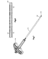
- FIG. 1 is a view of an adjustable balloon including bone access tip
- FIG. 2 is a cross-sectional view of a handle of the balloon of FIG. 1 ;
- FIG. 3 is a perspective view of a portion of an access cannula, an inner sleeve and a threaded sleeve of the balloon of FIG. 1 ;
- FIG. 4 is another cross-sectional view of the handle showing an inflation lumen and orifice of the inner sleeve
- FIG. 5 is a cross-sectional view of the inner sleeve and outer access cannula
- FIG. 6 is a cross-sectional view of a distal end of the inner sleeve and access cannula showing an inflatable structure
- FIG. 7 is a perspective view of the balloon of FIG. 1 showing the access cannula in a retracted position
- FIG. 8 is another cross-sectional view of the handle showing the threaded sleeve position with the access cannula in the retracted position;
- FIG. 9 shows the inflatable structure in an inflated state
- FIG. 10 is a perspective view of the balloon of FIG. 1 with the inflatable structure in an inflated state
- FIGS. 11-15 illustrate stages in a medical procedure using the balloon of the present disclosures.
- the balloon 100 includes a handle 102 having an inflation/communication port 110 and an inflation/communication port 112, an access cannula 104, a rotary handle 106, an inner sleeve 116 and sharp tip 108.
- the access cannula 104 and the inner sleeve 116 may be made from, e.g., metal or extruded plastic materials.
- the inner sleeve 116 extends within the access cannula 104 to support compliant, inflatable structure 122 (see, FIG. 6 ).
- the tip 108 is formed at a distal end of the inner sleeve 116 such that the inner sleeve 116 and tip 108 may be formed having a unitary construction.
- the tip 108 is sharp enough to provide access to, e.g., a vertebral body.
- the proximal ends of the inner sleeve 116 and the access cannula 104 are contained within the handle 102.
- the access cannula 104 may be retracted into the handle 102 by operation of the rotary handle 106 to expose the inflatable structure 122, such that the inflatable structure 122 may have an adjustable length.
- the access cannula 104 may include length indicators to show a length of the inflatable structure 122 as a result of the access cannula 104 being withdrawn into the handle 102 by the rotary handle 106.
- FIGS. 1-6 illustrate aspects of the balloon 100 in an extended position, where the inflatable structure 122 is disposed within the access cannula 104 and supported by the inner sleeve 116.
- the inflatable structure 122 may be made, e.g., from a deformable plastic or other compliant material. As will be described below, in use, the inflatable structure 122 is deployed and expanded inside bone, e.g., in a vertebral body, to compact cancellous bone and/or displace cortical bone.
- the proximal end of the inner sleeve 116 extends within the handle 102 and mates with the inflation/communication port 110 at a proximal end of the handle 102.
- the inner sleeve 116 also forms an inflation lumen 118 between and inner and outer wall thereof.
- the outer wall of the inner sleeve 116 also defines an orifice 120 of the inflation lumen 118 that interfaces with the inflation/communication port 112 on the handle 102.
- the proximal end of the inner sleeve 116 is sealed.
- the inflation/communication ports 110 and 112 may include luer fittings.
- the inflation/communication port 112 and the orifice 120 create an inflation port of the inflation lumen 118.
- the inflation/communication port 112 is positioned at an approximately right angle to the inflation/communication port 110 on the handle 102. Although the inflation/communication port 112 is shown at approximately at right angle, the inflation/communication port 112 may be positioned at any angle between 0° and 90°.
- a guidance wire may be extended through the inner sleeve 116 and the inflation/communication port 110 to direct the balloon 100 during use.
- the inflatable structure 122 is coupled at its proximal end to the inner wall and the outer wall of the inner sleeve 116 to allow for an inflation fluid within the inflation lumen 118 to enter and pressurize the inflatable structure 122.
- the inflation lumen 118 conveys a pressurized flowable medium, e.g., sterile water, radiopaque fluid, or other flowable substance into the inflatable structure 122, to expand it.
- the inflatable structure 122 is coupled at its distal end to a joint formed at the boundary between the inner sleeve 116 and a proximal wall of the tip 108.
- the inflatable structure 122 may be folded, etc. to fit within a space defined between the access cannula 104 and the inner sleeve 116.
- the rotary handle 106 may be used to retract the access cannula 104 into the handle 102.
- a threaded sleeve 114 which is attached to a proximal end of the access cannula 104, may be retracted (or extended) within an inner area of the rotary handled 106 by action of outer threads of the threaded sleeve 114 that cooperate with inner threads of the rotary handled 106.
- FIG. 8 shows the result of operation of the rotary handle 106 whereby the threaded sleeve 114 is retracted approximately one-half of the distance of the rotary handle 106.
- the inflatable structure 122 is exposed having an associated length and ready for inflation.
- the inflation/communication port 112 on the handle 102 serves to couple the inflation lumen 118 to the source of pressurized flowable medium (not shown) that is introduced within the inflation lumen 118 through the orifice 120.
- the inflatable structure 122 may be expanded as shown in FIGS. 9 and 10 .
- the inflation/communication port 110 may be used to introduce bone filler into, e.g., a vertebral body after an inflation operation, as described below.
- the material from which the inflatable structure 122 is made may possess various physical and mechanical properties to optimize its functional capabilities to compact cancellous bone. Such properties may include the ability to expand in volume, the ability to deform in a desired way when expanding and assume a desired shape inside bone, and/or the ability to withstand abrasion, tearing, and puncture when in contact with cancellous and/or cortical bone.
- FIGS. 11-15 illustrate stages of a procedure using the balloon 100 within a vertebral body.
- the expanded shape inside bone may be selected to optimize the formation of a cavity that, when filled with a selected, flowable material (e.g., PMMA, calcium phosphate, etc.), provides support across the region of the bone being treated.
- a selected, flowable material e.g., PMMA, calcium phosphate, etc.
- the balloon 100 is introduced within the vertebral body, with ( FIG. 12 ) or without ( FIG. 11 ) a guidance wire.
- the guidance wire may pass within the inner sleeve 116.
- the access cannula 104 is retracted by an amount appropriate to expose a selected length of the inflatable structure 112 by operation of the rotary handle 106.
- the access cannula 104 may be retracted an amount determined in accordance with the size pf the vertebral body.
- the inflatable structure need not have a predetermined length that is preselected based on the size of the vertebral body.
- the selection of the shape of the inflatable structure 122 inside bone may take into account the cancellous bone volume which should be compacted to achieve the desired therapeutic result.
- Another consideration for the selection of the shape of the inflatable structure 122 is the amount that the targeted fractured bone region has been displaced or depressed.
- the inflatable structure 122 is shown in an inflated state, which creates a cavity within, e.g., the cancellous bone of a vertebral body of a surgical area.
- the expansion of the inflatable structure 122 inside a bone may also elevate or push the fractured cortical wall back to or near its anatomic position occupied before fracture occurred.
- the inflatable structures is then deflated and the balloon 100 is retracted a small amount.
- the cavity is filled with a selected material 130 through, e.g., inflation/communication port 110.
- the procedure is described using a single balloon 100, the procedure may be performed using two balloons 100, each being introduced from opposite sides of the body.
Landscapes
- Health & Medical Sciences (AREA)
- Life Sciences & Earth Sciences (AREA)
- Orthopedic Medicine & Surgery (AREA)
- Surgery (AREA)
- Medical Informatics (AREA)
- Engineering & Computer Science (AREA)
- Biomedical Technology (AREA)
- Heart & Thoracic Surgery (AREA)
- Nuclear Medicine, Radiotherapy & Molecular Imaging (AREA)
- Molecular Biology (AREA)
- Animal Behavior & Ethology (AREA)
- General Health & Medical Sciences (AREA)
- Public Health (AREA)
- Veterinary Medicine (AREA)
- Surgical Instruments (AREA)
- Prostheses (AREA)
Abstract
Description
- Osteoporosis is a disease that gradually weakens bones and causes them to become brittle. Left untreated, osteoporosis can progress painlessly until a bone breaks. In some cases, osteoporosis can cause compression fractures in the spine. This occurs when the bony block, or vertebral body, in the spine collapses. This causes severe pain, deformity, and loss of height. It can also lead to nerve compression.
- Balloon based vertebral augmentation is a procedure that involves making small incisions and placing a catheter into the vertebral space where the fracture is located. A cavity is created inside the bone (e.g. drilled) and a balloon is inserted. The balloon may be support by a guidance wire that is passed through a central lumen of the catheter. The balloon is then inflated with contrast medium until it expands to a desired height, deflated and removed. The balloon is used to compress bone and reposition the vertebral body and to create a cavity for cement. The cavity created by the balloon may then be filled with PMMA, binding the fracture. The balloon based vertebral augmentation procedure has the potential to restore height to the spine, thus reducing deformity and also providing pain relief.
- However, the balloons utilized by vertebral augmentation balloon catheters are typically of a fixed size. Thus, to perform a vertebral augmentation balloon procedure, the surgeon must first select a balloon having an appropriate size for the vertebral body undergoing the procedure. A selection of an inappropriately-sized balloon may lead to unsuccessful result.
- Described is an adjustable balloon that includes a handle having an inflation port, an access cannula, a rotary handle, an inner sleeve and sharp tip. The inner sleeve extends within the access cannula to support a compliant, inflatable structure. The access cannula may be retracted into the handle by operation of the rotary handle to expose the inflatable structure, such that the inflatable structure may have an adjustable length. The access cannula may include length indicators to show a length of the inflatable structure as a result of the access cannula being withdrawn into the handle.
- In accordance with some implementations, there is provided a medical device for creating a cavity in bone. The device may include a handle, an inner sleeve extending from the handle that has a cutting tip, an inflatable structure that is supported by the inner sleeve, and an outer sleeve surround the inner sleeve that is retractable within the handle to reveal the inflatable structure.
- In accordance with some implementations, there is provided a method for treating bone using a balloon having an adjustable inflatable structure. The method may include introducing the balloon into a surgical region; retracting an outer sleeve of the balloon to expose the adjustable inflatable structure; inflating the adjustable inflatable structure to compress bone within the surgical region; deflating the adjustable inflatable structure to reveal a cavity within the surgical region; and introducing a flowable material to fill the cavity.
- In accordance with some implementations there is provided a medical device for creating a cavity in bone. The device may include a handle having an inflation port and an inner sleeve extending from the handle. The inner sleeve has a cutting tip and defines an inflation lumen between an inner wall and an outer wall thereof. The outer wall defines an orifice that communicates with the inflation port. An outer sleeve surrounds the inner sleeve, where the outer sleeve is retractable within the handle. An inflatable structure is supported by the inner sleeve and enclosed by the outer sleeve in a first position and is exposed when the outer sleeve is in a retracted position within the handle.
- This summary is provided to introduce a selection of concepts in a simplified form that are further described below in the detailed description. This summary is not intended to identify key features or essential features of the claimed subject matter, nor is it intended that this summary be used to limit the scope of the claimed subject matter. Furthermore, the claimed subject matter is not limited to implementations that solve any or all disadvantages noted in any part of this disclosure.
- To facilitate an understanding of and for the purpose of illustrating the present disclosure, exemplary features and implementations are disclosed in the accompanying drawings, it being understood, however, that the present disclosure is not limited to the precise arrangements and instrumentalities shown, and wherein similar reference characters denote similar elements throughout the several views, and wherein:
-
FIG. 1 is a view of an adjustable balloon including bone access tip; -
FIG. 2 is a cross-sectional view of a handle of the balloon ofFIG. 1 ; -
FIG. 3 is a perspective view of a portion of an access cannula, an inner sleeve and a threaded sleeve of the balloon ofFIG. 1 ; -
FIG. 4 is another cross-sectional view of the handle showing an inflation lumen and orifice of the inner sleeve; -
FIG. 5 is a cross-sectional view of the inner sleeve and outer access cannula; -
FIG. 6 is a cross-sectional view of a distal end of the inner sleeve and access cannula showing an inflatable structure; -
FIG. 7 is a perspective view of the balloon ofFIG. 1 showing the access cannula in a retracted position; -
FIG. 8 is another cross-sectional view of the handle showing the threaded sleeve position with the access cannula in the retracted position; -
FIG. 9 shows the inflatable structure in an inflated state; -
FIG. 10 is a perspective view of the balloon ofFIG. 1 with the inflatable structure in an inflated state; and -
FIGS. 11-15 illustrate stages in a medical procedure using the balloon of the present disclosures. - Referring now to
FIGS. 1-10 , there is illustrated aspects of anadjustable balloon 100. Theballoon 100 includes ahandle 102 having an inflation/communication port 110 and an inflation/communication port 112, anaccess cannula 104, arotary handle 106, aninner sleeve 116 andsharp tip 108. Theaccess cannula 104 and theinner sleeve 116 may be made from, e.g., metal or extruded plastic materials. Theinner sleeve 116 extends within theaccess cannula 104 to support compliant, inflatable structure 122 (see,FIG. 6 ). - The
tip 108 is formed at a distal end of theinner sleeve 116 such that theinner sleeve 116 andtip 108 may be formed having a unitary construction. Thetip 108 is sharp enough to provide access to, e.g., a vertebral body. The proximal ends of theinner sleeve 116 and theaccess cannula 104 are contained within thehandle 102. As will be described below, theaccess cannula 104 may be retracted into thehandle 102 by operation of therotary handle 106 to expose theinflatable structure 122, such that theinflatable structure 122 may have an adjustable length. Theaccess cannula 104 may include length indicators to show a length of theinflatable structure 122 as a result of theaccess cannula 104 being withdrawn into thehandle 102 by therotary handle 106. -
FIGS. 1-6 illustrate aspects of theballoon 100 in an extended position, where theinflatable structure 122 is disposed within theaccess cannula 104 and supported by theinner sleeve 116. Theinflatable structure 122 may be made, e.g., from a deformable plastic or other compliant material. As will be described below, in use, theinflatable structure 122 is deployed and expanded inside bone, e.g., in a vertebral body, to compact cancellous bone and/or displace cortical bone. - As shown in
FIGS. 2 and4 , the proximal end of theinner sleeve 116 extends within thehandle 102 and mates with the inflation/communication port 110 at a proximal end of thehandle 102. Theinner sleeve 116 also forms aninflation lumen 118 between and inner and outer wall thereof. The outer wall of theinner sleeve 116 also defines anorifice 120 of theinflation lumen 118 that interfaces with the inflation/communication port 112 on thehandle 102. The proximal end of theinner sleeve 116 is sealed. The inflation/communication ports - The inflation/
communication port 112 and theorifice 120 create an inflation port of theinflation lumen 118. The inflation/communication port 112 is positioned at an approximately right angle to the inflation/communication port 110 on thehandle 102. Although the inflation/communication port 112 is shown at approximately at right angle, the inflation/communication port 112 may be positioned at any angle between 0° and 90°. A guidance wire may be extended through theinner sleeve 116 and the inflation/communication port 110 to direct theballoon 100 during use. - As shown in
FIG. 5 , theinflatable structure 122 is coupled at its proximal end to the inner wall and the outer wall of theinner sleeve 116 to allow for an inflation fluid within theinflation lumen 118 to enter and pressurize theinflatable structure 122. In use, theinflation lumen 118 conveys a pressurized flowable medium, e.g., sterile water, radiopaque fluid, or other flowable substance into theinflatable structure 122, to expand it. Theinflatable structure 122 is coupled at its distal end to a joint formed at the boundary between theinner sleeve 116 and a proximal wall of thetip 108. Theinflatable structure 122 may be folded, etc. to fit within a space defined between theaccess cannula 104 and theinner sleeve 116. - As introduced above, the
rotary handle 106 may be used to retract theaccess cannula 104 into thehandle 102. For example, if therotary handle 106 is turned in a first direction, a threadedsleeve 114, which is attached to a proximal end of theaccess cannula 104, may be retracted (or extended) within an inner area of the rotary handled 106 by action of outer threads of the threadedsleeve 114 that cooperate with inner threads of the rotary handled 106.FIG. 8 shows the result of operation of therotary handle 106 whereby the threadedsleeve 114 is retracted approximately one-half of the distance of therotary handle 106. As such, as shown inFIG. 7 , theinflatable structure 122 is exposed having an associated length and ready for inflation. - In use, the inflation/
communication port 112 on the handle 102 (see, e.g.,FIG. 1 ) serves to couple theinflation lumen 118 to the source of pressurized flowable medium (not shown) that is introduced within theinflation lumen 118 through theorifice 120. Thus, theinflatable structure 122 may be expanded as shown inFIGS. 9 and10 . The inflation/communication port 110 may be used to introduce bone filler into, e.g., a vertebral body after an inflation operation, as described below. - The material from which the
inflatable structure 122 is made may possess various physical and mechanical properties to optimize its functional capabilities to compact cancellous bone. Such properties may include the ability to expand in volume, the ability to deform in a desired way when expanding and assume a desired shape inside bone, and/or the ability to withstand abrasion, tearing, and puncture when in contact with cancellous and/or cortical bone. -
FIGS. 11-15 illustrate stages of a procedure using theballoon 100 within a vertebral body. In general, when compressing cancellous bone and/or creating a cavity, the expanded shape inside bone may be selected to optimize the formation of a cavity that, when filled with a selected, flowable material (e.g., PMMA, calcium phosphate, etc.), provides support across the region of the bone being treated. InFIGS. 11-12 , theballoon 100 is introduced within the vertebral body, with (FIG. 12 ) or without (FIG. 11 ) a guidance wire. The guidance wire may pass within theinner sleeve 116. - In
FIG. 13 , theaccess cannula 104 is retracted by an amount appropriate to expose a selected length of theinflatable structure 112 by operation of therotary handle 106. For example, theaccess cannula 104 may be retracted an amount determined in accordance with the size pf the vertebral body. Thus, the inflatable structure need not have a predetermined length that is preselected based on the size of the vertebral body. In cases where the bone disease causing fracture is the loss of cancellous bone mass, as in osteoporosis, the selection of the shape of theinflatable structure 122 inside bone may take into account the cancellous bone volume which should be compacted to achieve the desired therapeutic result. Another consideration for the selection of the shape of theinflatable structure 122 is the amount that the targeted fractured bone region has been displaced or depressed. - In
FIG. 14 , theinflatable structure 122 is shown in an inflated state, which creates a cavity within, e.g., the cancellous bone of a vertebral body of a surgical area. The expansion of theinflatable structure 122 inside a bone may also elevate or push the fractured cortical wall back to or near its anatomic position occupied before fracture occurred. The inflatable structures is then deflated and theballoon 100 is retracted a small amount. InFig. 15 , the cavity is filled with a selectedmaterial 130 through, e.g., inflation/communication port 110. - Although the above procedure is described using a
single balloon 100, the procedure may be performed using twoballoons 100, each being introduced from opposite sides of the body. - The subject matter described above is provided by way of illustration only and should not be construed as limiting. Various modifications and changes may be made to the subject matter described herein without following the example embodiments and applications illustrated and described, and without departing from the true spirit and scope of the present invention, which is set forth in the following claims.
Claims (15)
- A medical device (100) for creating a cavity in bone, the device comprising:a handle (102);an inner sleeve (116) extending from the handle (102), the inner sleeve (116) having a cutting tip (108);an inflatable structure (122) that is supported by the inner sleeve (116); andan outer sleeve (104) surround the inner sleeve (116), the outer sleeve (104) being retractable within the handle (102) to reveal the inflatable structure (122).
- The medical device of claim 1, the handle (102) further comprising:a first port (112) for conveying a pressurized flowable medium to the inflatable structure (122); anda second port (110) for passing a guidance wire to guide the medical device (100) to a surgical area.
- The medical device of claim 2, wherein the inner sleeve (116) defines an inflation lumen (118) having an orifice (120), and wherein the orifice (120) receives the pressurized flowable medium from the first port (112) of the handle (102).
- The medical device of claim 2 or 3, wherein the second port (110) in the handle (102) is configured such that a biocompatible flowable material can be introduced into the surgical area through the second port (110) to stabilize bone in the surgical area.
- The medical device of any one of claims 1 to 4, wherein the inner sleeve (116) comprises an inner wall and an outer wall, and wherein an inflation lumen (118) is formed between and the inner wall and the outer wall to provide a pressurized flowable medium to the inflatable structure (122).
- The medical device of claim 5, wherein the inflatable structure (122) is coupled at a proximal end to the inner wall and the outer wall of the inner sleeve (116), and wherein the inflatable structure (122) is coupled at a distal end to a joint formed at a boundary between the inner sleeve (116) and a proximal wall of the cutting tip (108).
- The medical device of claim 1, wherein the handle (102) has an inflation port (112), the inner sleeve (116) defines an inflation lumen (118) between an inner wall and an outer wall thereof, the outer wall defining an orifice (120) that communicates with the inflation port (112), the inflatable structure (122) is enclosed by the outer sleeve (104) in a first position, and wherein the inflatable structure (122) is exposed when the outer sleeve (104) is in a retracted position within the handle (102).
- The medical device of claim 7, the handle further comprising a second port for passing a guidance wire or introducing bone cement into a surgical area.
- The medical device of claim 7, the handle further comprising a second port that is configured such that a biocompatible flowable material can be introduced into a surgical area through the second port in the handle to stabilize bone in the surgical area.
- The medical device of any one of claims 7 to 9, wherein the inflation port (112) is configured such that a pressurized flowable medium can be provided to the inflatable structure (122) via the inflation port (112).
- The medical device of any one of claims 1 to 10, the handle (102) further comprising a rotary handle (106), wherein operation of the rotary handle (106) retracts the outer sleeve (104) into the handle (102).
- The medical device of claim 11, further comprising a threaded sleeve (114) that is attached to a proximal end of the outer sleeve (104), wherein the threaded sleeve (114) cooperates with the rotary handle (106) to retract the outer sleeve (104) into the handle (102).
- The medical device of any one of claims 1 to 12, wherein length indicators are provided on an outer surface of the outer sleeve (104) to show a length of the inflatable structure (122) as a result of the outer sleeve (104) being retracted into the handle (102).
- The medical device of any one of claims 1 to 13, wherein the inflatable structure (122) is made from a deformable plastic or compliant material.
- The medical device of any one of claims 1 to 14, wherein the inflatable structure (122) has an adjustable size.
Applications Claiming Priority (1)
| Application Number | Priority Date | Filing Date | Title |
|---|---|---|---|
| US13/399,009 US10034700B2 (en) | 2012-02-17 | 2012-02-17 | Adjustable balloon including bone access tip |
Publications (1)
| Publication Number | Publication Date |
|---|---|
| EP2628457A1 true EP2628457A1 (en) | 2013-08-21 |
Family
ID=47757335
Family Applications (1)
| Application Number | Title | Priority Date | Filing Date |
|---|---|---|---|
| EP13155443.8A Withdrawn EP2628457A1 (en) | 2012-02-17 | 2013-02-15 | Adjustable balloon including access tip |
Country Status (2)
| Country | Link |
|---|---|
| US (2) | US10034700B2 (en) |
| EP (1) | EP2628457A1 (en) |
Families Citing this family (6)
| Publication number | Priority date | Publication date | Assignee | Title |
|---|---|---|---|---|
| DE10154163A1 (en) * | 2001-11-03 | 2003-05-22 | Advanced Med Tech | Device for straightening and stabilizing the spine |
| RU2013126242A (en) | 2010-11-12 | 2014-12-20 | Смит Энд Нефью, Инк. | INFLATABLE CONTROLLED CYLINDER FOR LIFTING FABRIC INSIDE THE BODY |
| WO2014039998A1 (en) * | 2012-09-07 | 2014-03-13 | Zimmer Knee Creations, Inc. | Subchondral treatment of bone defects with bone-derived implant |
| DE112018006160T5 (en) | 2017-12-28 | 2020-09-03 | Cardio Voyage Innovations, LLC. | DEVICE FOR DIRECTIVE KYPHOPLASTY AND METHOD OF USING SUCH DEVICE |
| CN111281483B (en) * | 2020-03-06 | 2024-08-13 | 华中科技大学同济医学院附属协和医院 | Bone marrow focus removing device and using method thereof |
| US11298238B1 (en) * | 2021-07-23 | 2022-04-12 | Focus Medical Company, Llc | Balloon kyphoplasty surgical device and method |
Citations (4)
| Publication number | Priority date | Publication date | Assignee | Title |
|---|---|---|---|---|
| US20090299378A1 (en) * | 2008-06-02 | 2009-12-03 | Knopp Peter G | Controlled deployment handles for bone stabilization devices |
| US20090326538A1 (en) * | 2006-12-15 | 2009-12-31 | Sennett Andrew R | Devices and methods for fracture reduction |
| US20110054416A1 (en) * | 2007-09-14 | 2011-03-03 | Hollowell Daniel R | Material control device for inserting material into a targeted anatomical region |
| US20110251615A1 (en) * | 2010-04-08 | 2011-10-13 | Dfine, Inc. | System for use in treatment of vertebral fractures |
Family Cites Families (11)
| Publication number | Priority date | Publication date | Assignee | Title |
|---|---|---|---|---|
| US6719773B1 (en) * | 1998-06-01 | 2004-04-13 | Kyphon Inc. | Expandable structures for deployment in interior body regions |
| US8613744B2 (en) * | 2002-09-30 | 2013-12-24 | Relievant Medsystems, Inc. | Systems and methods for navigating an instrument through bone |
| WO2005096970A2 (en) * | 2004-03-31 | 2005-10-20 | Advanced Biomaterial Systems, Inc. | Methods and devices for cavity creation in mammalian bone tissue |
| US7465318B2 (en) * | 2004-04-15 | 2008-12-16 | Soteira, Inc. | Cement-directing orthopedic implants |
| US8403937B2 (en) * | 2007-03-30 | 2013-03-26 | Kyphon Sarl | Apparatus and method for medical procedures within a spine |
| US8262609B2 (en) * | 2009-10-29 | 2012-09-11 | Kyphon Sarl | Anterior inflation balloon |
| US20120010624A1 (en) * | 2009-12-07 | 2012-01-12 | O'halloran Damien | Methods and Apparatus For Treating Vertebral Fractures |
| US8734458B2 (en) * | 2009-12-07 | 2014-05-27 | Globus Medical, Inc. | Methods and apparatus for treating vertebral fractures |
| US8454615B2 (en) * | 2011-07-05 | 2013-06-04 | Kyphon Sarl | Combination directional and non-directional bone tamp |
| US9387030B2 (en) * | 2013-01-07 | 2016-07-12 | Kyphon SÀRL | Catheter with integrated cement delivery balloon |
| US10595918B2 (en) * | 2018-01-08 | 2020-03-24 | Medtronic Holding Company Sàrl | High-pressure balloon catheter with pressure regulating valve |
-
2012
- 2012-02-17 US US13/399,009 patent/US10034700B2/en active Active
-
2013
- 2013-02-15 EP EP13155443.8A patent/EP2628457A1/en not_active Withdrawn
-
2018
- 2018-07-30 US US16/048,993 patent/US11033313B2/en active Active
Patent Citations (4)
| Publication number | Priority date | Publication date | Assignee | Title |
|---|---|---|---|---|
| US20090326538A1 (en) * | 2006-12-15 | 2009-12-31 | Sennett Andrew R | Devices and methods for fracture reduction |
| US20110054416A1 (en) * | 2007-09-14 | 2011-03-03 | Hollowell Daniel R | Material control device for inserting material into a targeted anatomical region |
| US20090299378A1 (en) * | 2008-06-02 | 2009-12-03 | Knopp Peter G | Controlled deployment handles for bone stabilization devices |
| US20110251615A1 (en) * | 2010-04-08 | 2011-10-13 | Dfine, Inc. | System for use in treatment of vertebral fractures |
Also Published As
| Publication number | Publication date |
|---|---|
| US20130218164A1 (en) | 2013-08-22 |
| US10034700B2 (en) | 2018-07-31 |
| US20190059966A1 (en) | 2019-02-28 |
| US11033313B2 (en) | 2021-06-15 |
Similar Documents
| Publication | Publication Date | Title |
|---|---|---|
| US11666366B2 (en) | Systems and methods for vertebral or other bone structure height restoration and stabilization | |
| US11033313B2 (en) | Adjustable balloon including bone access tip | |
| US10278755B2 (en) | Double threaded guidance or stiffening wire for multiple use vertebral augmentation (VA) balloon | |
| US10405907B2 (en) | Low cost low profile inflatable bone tamp | |
| KR101179856B1 (en) | Insertion devices and method of use | |
| US8262609B2 (en) | Anterior inflation balloon | |
| JP2007044544A (en) | Device for treating fractured and/or diseased bone | |
| EP2627288A1 (en) | Double threaded guidance or stiffening wire for multiple use vertebral augmentation (va) balloon | |
| US9393061B2 (en) | Method for balloon-assisted augmentation and fusion of adjacent vertebral bodies | |
| AU2014332328B2 (en) | Systems for balloon-aided vertebral augmentation |
Legal Events
| Date | Code | Title | Description |
|---|---|---|---|
| PUAI | Public reference made under article 153(3) epc to a published international application that has entered the european phase |
Free format text: ORIGINAL CODE: 0009012 |
|
| AK | Designated contracting states |
Kind code of ref document: A1 Designated state(s): AL AT BE BG CH CY CZ DE DK EE ES FI FR GB GR HR HU IE IS IT LI LT LU LV MC MK MT NL NO PL PT RO RS SE SI SK SM TR |
|
| AX | Request for extension of the european patent |
Extension state: BA ME |
|
| 17P | Request for examination filed |
Effective date: 20140121 |
|
| RBV | Designated contracting states (corrected) |
Designated state(s): AL AT BE BG CH CY CZ DE DK EE ES FI FR GB GR HR HU IE IS IT LI LT LU LV MC MK MT NL NO PL PT RO RS SE SI SK SM TR |
|
| STAA | Information on the status of an ep patent application or granted ep patent |
Free format text: STATUS: EXAMINATION IS IN PROGRESS |
|
| 17Q | First examination report despatched |
Effective date: 20171109 |
|
| STAA | Information on the status of an ep patent application or granted ep patent |
Free format text: STATUS: EXAMINATION IS IN PROGRESS |
|
| GRAP | Despatch of communication of intention to grant a patent |
Free format text: ORIGINAL CODE: EPIDOSNIGR1 |
|
| STAA | Information on the status of an ep patent application or granted ep patent |
Free format text: STATUS: GRANT OF PATENT IS INTENDED |
|
| INTG | Intention to grant announced |
Effective date: 20211004 |
|
| STAA | Information on the status of an ep patent application or granted ep patent |
Free format text: STATUS: THE APPLICATION IS DEEMED TO BE WITHDRAWN |
|
| 18D | Application deemed to be withdrawn |
Effective date: 20220215 |