EP2628449A2 - Ultrasound apparatus and method of generating ultrasound image - Google Patents
Ultrasound apparatus and method of generating ultrasound image Download PDFInfo
- Publication number
- EP2628449A2 EP2628449A2 EP13155425.5A EP13155425A EP2628449A2 EP 2628449 A2 EP2628449 A2 EP 2628449A2 EP 13155425 A EP13155425 A EP 13155425A EP 2628449 A2 EP2628449 A2 EP 2628449A2
- Authority
- EP
- European Patent Office
- Prior art keywords
- vector information
- velocity
- predetermined point
- prediction
- ultrasound
- Prior art date
- Legal status (The legal status is an assumption and is not a legal conclusion. Google has not performed a legal analysis and makes no representation as to the accuracy of the status listed.)
- Granted
Links
Images


Classifications
-
- A—HUMAN NECESSITIES
- A61—MEDICAL OR VETERINARY SCIENCE; HYGIENE
- A61B—DIAGNOSIS; SURGERY; IDENTIFICATION
- A61B8/00—Diagnosis using ultrasonic, sonic or infrasonic waves
- A61B8/54—Control of the diagnostic device
-
- A—HUMAN NECESSITIES
- A61—MEDICAL OR VETERINARY SCIENCE; HYGIENE
- A61B—DIAGNOSIS; SURGERY; IDENTIFICATION
- A61B8/00—Diagnosis using ultrasonic, sonic or infrasonic waves
- A61B8/08—Detecting organic movements or changes, e.g. tumours, cysts, swellings
- A61B8/0891—Detecting organic movements or changes, e.g. tumours, cysts, swellings for diagnosis of blood vessels
-
- A—HUMAN NECESSITIES
- A61—MEDICAL OR VETERINARY SCIENCE; HYGIENE
- A61B—DIAGNOSIS; SURGERY; IDENTIFICATION
- A61B8/00—Diagnosis using ultrasonic, sonic or infrasonic waves
- A61B8/48—Diagnostic techniques
- A61B8/488—Diagnostic techniques involving Doppler signals
-
- A—HUMAN NECESSITIES
- A61—MEDICAL OR VETERINARY SCIENCE; HYGIENE
- A61B—DIAGNOSIS; SURGERY; IDENTIFICATION
- A61B8/00—Diagnosis using ultrasonic, sonic or infrasonic waves
- A61B8/52—Devices using data or image processing specially adapted for diagnosis using ultrasonic, sonic or infrasonic waves
- A61B8/5207—Devices using data or image processing specially adapted for diagnosis using ultrasonic, sonic or infrasonic waves involving processing of raw data to produce diagnostic data, e.g. for generating an image
-
- G—PHYSICS
- G01—MEASURING; TESTING
- G01S—RADIO DIRECTION-FINDING; RADIO NAVIGATION; DETERMINING DISTANCE OR VELOCITY BY USE OF RADIO WAVES; LOCATING OR PRESENCE-DETECTING BY USE OF THE REFLECTION OR RERADIATION OF RADIO WAVES; ANALOGOUS ARRANGEMENTS USING OTHER WAVES
- G01S15/00—Systems using the reflection or reradiation of acoustic waves, e.g. sonar systems
- G01S15/88—Sonar systems specially adapted for specific applications
- G01S15/89—Sonar systems specially adapted for specific applications for mapping or imaging
- G01S15/8906—Short-range imaging systems; Acoustic microscope systems using pulse-echo techniques
- G01S15/8979—Combined Doppler and pulse-echo imaging systems
- G01S15/8984—Measuring the velocity vector
-
- A—HUMAN NECESSITIES
- A61—MEDICAL OR VETERINARY SCIENCE; HYGIENE
- A61B—DIAGNOSIS; SURGERY; IDENTIFICATION
- A61B8/00—Diagnosis using ultrasonic, sonic or infrasonic waves
- A61B8/46—Ultrasonic, sonic or infrasonic diagnostic devices with special arrangements for interfacing with the operator or the patient
- A61B8/467—Ultrasonic, sonic or infrasonic diagnostic devices with special arrangements for interfacing with the operator or the patient characterised by special input means
- A61B8/469—Ultrasonic, sonic or infrasonic diagnostic devices with special arrangements for interfacing with the operator or the patient characterised by special input means for selection of a region of interest
-
- G—PHYSICS
- G01—MEASURING; TESTING
- G01S—RADIO DIRECTION-FINDING; RADIO NAVIGATION; DETERMINING DISTANCE OR VELOCITY BY USE OF RADIO WAVES; LOCATING OR PRESENCE-DETECTING BY USE OF THE REFLECTION OR RERADIATION OF RADIO WAVES; ANALOGOUS ARRANGEMENTS USING OTHER WAVES
- G01S7/00—Details of systems according to groups G01S13/00, G01S15/00, G01S17/00
- G01S7/52—Details of systems according to groups G01S13/00, G01S15/00, G01S17/00 of systems according to group G01S15/00
- G01S7/52017—Details of systems according to groups G01S13/00, G01S15/00, G01S17/00 of systems according to group G01S15/00 particularly adapted to short-range imaging
- G01S7/52053—Display arrangements
- G01S7/52057—Cathode ray tube displays
- G01S7/52071—Multicolour displays; using colour coding; Optimising colour or information content in displays, e.g. parametric imaging
Definitions
- the present disclosure relates to a method and apparatus for generating an ultrasound image and, more particularly, to a method and apparatus for generating a Doppler image of an object.
- Ultrasound apparatuses are used to monitor the internal structure of an organic body. Ultrasound apparatuses are non-invasive test devices and show structural details, tissues, and fluidic flows in the body.
- An ultrasound apparatus may display the flow of blood or movement of tissues as a color Doppler image or a spectral Doppler image, and a user may view the color Doppler image or the spectral Doppler image to check the motion of heart valves, a blood velocity or a blood flow rate in blood vessels, or the like.
- the color Doppler image and the spectral Doppler image include information about a velocity magnitude and a velocity direction of a blood flow or tissues, a method of accurately measuring the information is required.
- the present disclosure provides an ultrasound apparatus and a method of generating an ultrasound image which are capable of accurately measuring vector information of an object.
- the present disclosure also provides an ultrasound apparatus and a method of generating an ultrasound image which are capable of providing a reliable color Doppler image or a reliable spectral Doppler image to a user.
- a method of generating an ultrasound image including transmitting an ultrasound signal to a predetermined point included in an object and receiving at least three response signals reflected from the predetermined point; extracting a plurality of response signal pairs by combining the received at least three response signals two-by-two; obtaining a plurality of pieces of prediction vector information, each of the pieces of prediction vector information indicating a prediction velocity magnitude and a prediction velocity direction of the predetermined point, based on reception angles and Doppler frequencies of the response signals included in the plurality of response signal pairs; and determining vector information indicating a velocity magnitude and a velocity direction of the predetermined point, based on the plurality of pieces of prediction vector information.
- the determining of the vector information may include determining the vector information based on a linear vector sum of the plurality of pieces of prediction vector information.
- the determining of the vector information may include determining any one of the plurality of prediction velocity directions included in the plurality of pieces of prediction vector information, as the velocity direction of the predetermined point; and determining a linear sum of the plurality of prediction velocity magnitudes included in the plurality of pieces of prediction vector information, as the velocity magnitude of the predetermined point.
- the method may further include determining vector information of a plurality of additional points located within a preset distance from the predetermined point.
- the determining of the vector information may include compensating for the velocity direction of the predetermined point by applying a smoothing filter to velocity directions of the plurality of additional points; and determining the compensated velocity direction as the velocity direction of the predetermined point.
- the determining of the vector information may include compensating for the velocity magnitude of the predetermined point by applying a smoothing filter to velocity magnitudes of the plurality of additional points; and determining the compensated velocity magnitude as the velocity magnitude of the predetermined point.
- the transmitting of the ultrasound signal may include transmitting the ultrasound signal a plurality of times and receiving each of the at least three response signals a plurality of times, a plurality of the same received response signal forming ensemble signals for the respective response signal, and the obtaining of the plurality of pieces of prediction vector information may include obtaining a Doppler frequency of each response signal included in the plurality of response signal pairs by using autocorrelation between the ensemble signals of the response signals.
- a method of generating an ultrasound image including transmitting an ultrasound signal to a point included in an object and receiving a response signal reflected from the point; determining vector information indicating a velocity magnitude of the point, based on a reception angle and a Doppler frequency of the response signal; and displaying a color Doppler image of the object by mapping the velocity magnitude of the point to a color scale.
- the method may further include determining vector information including a velocity direction of a plurality of points included in the object; estimating an overall velocity direction of the object by using the velocity directions of the plurality of points; and displaying the color Doppler image of the object by mapping angle differences between the velocity directions of the plurality of points and the overall velocity direction of the object to a color scale.
- the method may further include determining vector information including a velocity magnitude of a plurality of points included in the object, and the displaying of the color Doppler image of the object may include mapping a velocity magnitude of a point having a first velocity direction component, from among the plurality of points, to a first color and mapping a velocity magnitude of a point having a second velocity direction component opposite to the first velocity direction component, from among the plurality of points, to a second color.
- a method of generating an ultrasound image including dividing an object into a plurality of regions; transmitting an ultrasound signal to the plurality of regions and receiving response signals reflected from the plurality of regions; measuring power levels or Doppler frequencies of the received response signals; and determining a monitoring region from among the plurality of regions by using the power levels or the Doppler frequencies of the received response signals.
- the determining of the monitoring region may include arbitrarily setting an initial region from among the plurality of regions; and determining one of the regions reflecting response signals having Doppler frequencies in a first predetermined range, which is closest to the initial region, as the monitoring region.
- the determining of the monitoring region may include determining one of the regions reflecting a response signal having a Doppler frequency in a second predetermined range, as the monitoring region.
- the determining of the monitoring region may include arbitrarily setting an initial region from among the plurality of regions; and determining one of the regions reflecting response signals having power levels in a third predetermined range, which is closest to the initial region, as the monitoring region.
- the determining of the monitoring region may include determining one of the regions reflecting a response signal having a power level in a fourth predetermined range, as the monitoring region.
- the determining of the monitoring region may include determining one of the regions reflecting a response signal having a power level in a fifth predetermined range from among the response signals that pass through a clutter filter, as the monitoring region.
- the method may further include adjusting a region of interest in such a way that the monitoring region is included in the region of interest.
- the method may further include adjusting a range gate in such a way that the range gate is located in the monitoring region.
- the method may further include measuring power levels or Doppler frequencies of response signals reflected from a plurality of the regions located within a preset distance from the monitoring region; obtaining a modeled line by applying a fitting method to the power levels or the Doppler frequencies of the response signals reflected from the plurality of regions; determining a blood vessel direction of the object based on the obtained modeled line; and adjusting a steering angle of the ultrasound signal in such a way that an angle between the blood vessel direction and an incident direction of the ultrasound signal transmitted to the plurality of regions is a predetermined angle.
- an ultrasound apparatus including a probe which transmits an ultrasound signal to a predetermined point included in an object and receives at least three response signals reflected from the predetermined point; an extraction unit which extracts a plurality of response signal pairs by combining the received at least three response signals two-by-two; a vector information obtaining unit which obtains a plurality of pieces of prediction vector information, each of the pieces of prediction vector information indicating a prediction velocity magnitude and a prediction velocity direction of the predetermined point, based on reception angles and Doppler frequencies of response signals included in the plurality of response signal pairs; and a vector information determination unit which determines vector information indicating a velocity magnitude and a velocity direction of the predetermined point, based on the plurality of pieces of prediction vector information.
- the vector information determination unit may determine the vector information by using a linear vector sum of the plurality of pieces of prediction vector information.
- the vector information determination unit may determine any one of the plurality of prediction velocity directions included in the plurality of pieces of prediction vector information, as the velocity direction of the predetermined point, and may determine a linear sum of the plurality of prediction velocity magnitudes included in the plurality of pieces of prediction vector information, as the velocity magnitude of the predetermined point.
- the vector information determination unit may determine vector information of a plurality of additional points located within a preset distance from the predetermined point.
- the vector information determination unit may compensate for the velocity direction of the predetermined point by applying a smoothing filter to velocity directions of the plurality of additional points, and may determine the compensated velocity direction as the velocity direction of the predetermined point.
- the vector information determination unit may compensate for the velocity magnitude of the predetermined point by applying a smoothing filter to velocity magnitudes of the plurality of additional points, and may determine the compensated velocity magnitude as the velocity magnitude of the predetermined point.
- the probe may transmit the ultrasound signal a plurality of times and receive each of the at least three response signals a plurality of times, a plurality of the same received response signal forming ensemble signals for the respective response signal, and the vector information obtaining unit may obtain a Doppler frequency of each response signal included in the plurality of response signal pairs by using autocorrelation between the ensemble signals of the response signals.
- an ultrasound apparatus including a probe which transmits an ultrasound signal to a point included in an object and receives a response signal reflected from the point; a vector information determination unit which determines vector information indicating a velocity magnitude of the point, based on a reception angle and a Doppler frequency of the response signal; and a display unit which displays a color Doppler image of the object by mapping the velocity magnitude of the point to a color scale.
- the vector information determination unit may determine vector information including velocity directions of a plurality of points included in the object and estimates an overall velocity direction of the object by using the velocity directions of the plurality of points, and the display unit may display the color Doppler image of the object by mapping angle differences between the velocity directions of the plurality of points and the overall velocity direction of the object to a color scale.
- the vector information determination unit may determine vector information including a vector magnitude of a plurality of points included in the object, and the display unit may map a velocity magnitude of a point having a first velocity direction component, from among the plurality of points, to a first color and may map a velocity magnitude of a point having a second velocity direction component opposite to the first velocity direction component, from among the plurality of points, to a second color.
- an ultrasound apparatus including a region dividing unit which divides an object into a plurality of regions; a probe which transmits an ultrasound signal to the plurality of regions and receives response signals reflected from the plurality of regions; a measurement unit which measures power levels or Doppler frequencies of the received response signals; and a control unit which determines a monitoring region from among the plurality of regions by using the power levels or the Doppler frequencies of the received response signals.
- the control unit arbitrarily may set an initial region from among the plurality of regions, and may determine one of the regions reflecting response signals having Doppler frequencies in a first predetermined range, which is closest to the initial region, as the monitoring region.
- the control unit may determine one of the regions reflecting a response signal having a Doppler frequency in a second predetermined range, as the monitoring region.
- the control unit may arbitrarily set an initial region from among the plurality of regions, and may determine one of the regions reflecting response signals having power levels in a third predetermined range, which is closest to the initial region, as the monitoring region.
- the control unit may determine one of the regions reflecting a response signal having a power level in a fourth predetermined range, as the monitoring region.
- the control unit may determine one of the regions reflecting a response signal having a power level in a fifth predetermined range from among the response signals that pass through a clutter filter, as the monitoring region.
- the control unit may adjust a region of interest in such a way that the monitoring region is included in the region of interest.
- the control unit may adjust a range gate in such a way that the range gate is located in the monitoring region.
- the measurement unit may measure power levels or Doppler frequencies of response signals reflected from a plurality of the regions located within a preset distance from the monitoring region, and the control unit may determine a blood vessel direction of the object based on a modeled line obtained by applying a fitting method to the power levels or the Doppler frequencies of the response signals reflected from the plurality of regions, and may adjust a steering angle of the ultrasound signal in such a way that an angle between the blood vessel direction and an incident direction of the ultrasound signal transmitted to the plurality of regions is a predetermined angle.
- a non-transitory computer-readable recording medium having recorded thereon a computer program for executing the method according to exemplary embodiments.
- an ultrasound apparatus including a probe which transmits an ultrasound signal to a point of an object and receives a plurality of response signals reflected back from the point, and a vector information determiner which determines a velocity direction and a velocity magnitude of the point based on the response signals, wherein, for each of the plurality of response signals, an angle between a reflection direction of the response signal and a velocity direction of the point is less than or greater than 90°.
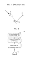
- FIG. 1 is a schematic diagram for describing a general method of obtaining a velocity magnitude of an object
- FIG. 2 is a block diagram of an ultrasound apparatus according to an exemplary embodiment
- FIG. 3 is a schematic diagram showing an ultrasound signal being transmitted to a predetermined point of an object and response signals being received from the predetermined point using the ultrasound apparatus illustrated in FIG. 2 ;
- FIG. 4 is a schematic diagram for describing a method of obtaining vector information of the predetermined point of the object using the ultrasound apparatus illustrated in FIG. 2 ;
- FIG. 5A is a schematic diagram showing vector information of a plurality of points of the object obtained using the ultrasound apparatus illustrated in FIG. 2 ;
- FIG. 5B is a schematic diagram showing a result of applying a smoothing filter to the vector information illustrated in FIG. 5A ;
- FIG. 6 is a block diagram of an ultrasound apparatus according to another exemplary embodiment
- FIGS. 7A and 7B are color Doppler images in which vector information of a plurality of points of an object is mapped to a color scale
- FIG. 8 is a flowchart of a method of generating an ultrasound image, according to an exemplary embodiment
- FIG. 9 is a block diagram of an ultrasound apparatus according to another exemplary embodiment.
- FIG. 10 is a schematic diagram for describing a method of determining a monitoring region from among a plurality of regions of an object, using the ultrasound apparatus illustrated in FIG. 9 ;
- FIG. 11 is a schematic diagram for describing another method of determining a monitoring region from among a plurality of regions of an object, using the ultrasound apparatus illustrated in FIG. 9 ;
- FIG. 12 is a schematic diagram for describing a method of determining a location of a blood vessel included in an object, using the ultrasound apparatus illustrated in FIG. 9 ;
- FIG. 13 is a schematic diagram for describing a method of adjusting a steering angle of an ultrasound signal, using the ultrasound apparatus illustrated in FIG. 9 ;
- FIG. 14 is a flowchart of a method of generating an ultrasound image, according to another exemplary embodiment.
- unit in the exemplary embodiments of the present disclosure may refer to a software component or a hardware component, such as a field-programmable gate array (FPGA) or an application-specific integrated circuit (ASIC), that performs a specific function.
- FPGA field-programmable gate array
- ASIC application-specific integrated circuit
- the term “unit” is not limited to software or hardware.
- the “unit” may be formed so as to be stored in an addressable storage medium, or may be formed so as to operate one or more processors.
- the term “unit” may refer to components such as software components, object-oriented software components, class components, and task components, processes, functions, properties, procedures, subroutines, segments of program codes, drivers, firmware, micro codes, circuits, data, databases, data structures, tables, arrays, and parameters. Functions provided by elements and “units” may be combined in a smaller number of elements and “units” or may be separated into additional elements and “units”.
- the term 'vector information' refers to a vector value indicating a velocity magnitude and a velocity direction
- the term 'velocity magnitude' refers to a scalar value not indicating a direction of a velocity but indicating only a magnitude of the velocity
- the term 'velocity direction' refers to a direction in which a certain point of an object moves at an arbitrary time.
- FIG. 1 is a schematic diagram for describing a general method of obtaining a velocity magnitude of an object 20.
- an 'object' refers to a certain body part of which an ultrasound image is to be obtained, e.g., tissue, blood, or an organ.
- a predetermined point P (22) of the object moves at a velocity magnitude v and in a velocity direction A.
- a probe 10 of an ultrasound apparatus transmits an ultrasound signal having a frequency f0 to the predetermined point P 22 and receives a response signal reflected from the predetermined point P (22).
- a frequency of the response signal varies according to the velocity magnitude v of the predetermined point P (22) and an angle ⁇ between an incident direction of the ultrasound signal and the velocity direction A of the predetermined point P (22), and a difference between the frequency of the ultrasound signal transmitted to the predetermined point P (22) and the frequency of the response signal is referred to as a Doppler frequency.
- a signal having the Doppler frequency is referred to as a Doppler signal.
- the velocity magnitude v of the predetermined point P (22) may be obtained by using the Doppler frequency.
- a velocity magnitude of the point may be accurately measured. However, a velocity magnitude of a point that is moving in another direction may not be accurately measured. In particular, if an angle between a velocity direction of each point and an incident direction of an ultrasound signal transmitted to an object is 90°, since a Doppler frequency is 0 Hz, a velocity magnitude of the point is measured as 0.
- FIG. 2 is a block diagram of an ultrasound apparatus 100 according to an exemplary embodiment.
- the ultrasound apparatus 100 includes a probe 110, an extraction unit 120, a vector information obtaining unit 130, and a vector information determination unit 140 (also referred to as vector information determiner).
- the extraction unit 120, the vector information obtaining unit 130, and the vector information determination unit 140 may be formed as microprocessors, although are not limited thereto.
- the probe 110 includes a plurality of piezoelectric elements, and transmits an ultrasound signal to a predetermined point P (22) of an object and receives at least three response signals reflected from the predetermined point P (22).
- Each of the at least three response signals may have a Doppler frequency and a reception angle that is an incident angle from the probe 110.
- FIG. 3 is a schematic diagram showing an ultrasound signal T being transmitted to a predetermined point P (22) of an object and response signals R 1 , R 2 , and R 3 being received from the predetermined point P (22), using the ultrasound apparatus 100 illustrated in FIG. 2 .
- the probe 110 transmits the ultrasound signal T to the predetermined point P (22) in a blood vessel 24 of the object and receives the response signals R 1 , R 2 , and R 3 reflected from the predetermined point P (22).
- the response signals R 1 , R 2 , and R 3 respectively have reception angles ⁇ 1 , ⁇ 2 , and ⁇ 3 .
- the probe 110 may transmit the ultrasound signal T to the predetermined point P (22) of the object a plurality of times and may receive each of the at least three response signals reflected from the predetermined point P (22) a plurality of times.
- the probe 110 receives each of the response signals R 1 , R 2 , and R 3 a plurality of times.
- a plurality of response signals R 1 , a plurality of response signals R 2 , and a plurality of response signals R 3 are referred to as ensemble signals. That is, ensemble signals refer to a plurality of response signals received at the same reception angle.
- a response signal pair R 12 may be extracted by combining the response signals R 1 and R 2
- a response signal pair R 13 may be extracted by combining the response signals R 1 and R 3
- a response signal pair R 23 may be extracted by combining the response signals R 2 and R 3 .
- the vector information obtaining unit 130 obtains a plurality of pieces of prediction vector information indicating a prediction velocity magnitude and a prediction velocity direction of the predetermined point P (22), based on reception angles and Doppler frequencies of response signals included in the plurality of response signal pairs.
- the vector information obtaining unit 130 may obtain a Doppler frequency of each response signal included in the plurality of response signal pairs by using autocorrelation between ensemble signals of the response signal.
- the vector information determination unit 140 determines vector information indicating a velocity magnitude and a velocity direction of the predetermined point P (22) of the object, by using the plurality of pieces of prediction vector information.
- vector information of a predetermined point of an object is obtained by using only two response signals reflected from the predetermined point.
- an angle between a reflection direction of any one response signal and a velocity direction of the predetermined point is close to 90°, accurate vector information may not be obtained.
- vector information of the predetermined point P (22) of the object is obtained by using at least three response signals reflected from the predetermined point P (22), accurate vector information may be obtained.
- FIG. 4 is a schematic diagram for describing a method of obtaining vector information V of the predetermined point P (22) of the object, using the ultrasound apparatus 100 illustrated in FIG. 2 .
- FIG. 4 shows three pieces of prediction vector information V 12 , V 23 , and V 13 obtained by using response signal pairs of three response signals reflected from the predetermined point P (22) in the blood vessel 24.
- the vector information determination unit 140 may obtain vector information V of the predetermined point P (22) by using a linear vector sum of the pieces of prediction vector information V 12 , V 23 , and V 13 .
- the vector information determination unit 140 may obtain the vector information V of the predetermined point P (22) by using Equation 1.
- V a ⁇ V 12 + b ⁇ V 23 + c ⁇ V 13 a ⁇ b ⁇ and c are real numbers
- the vector information V may be a simple vector sum of the pieces of prediction vector information V 12 , V 23 , and V 13 . If all of a, b, and c are set as 1/3, the vector information V may be an average of the pieces of prediction vector information V 12 , V 23 , and V 13 . Alternatively, a, b, and c may be set as different real numbers to apply a weight to a certain piece of prediction vector information.
- a prediction velocity direction included in each piece of prediction vector information is not significantly different from an actual velocity direction of the predetermined point P (22), and a significant difference does not exist between prediction velocity directions.
- the vector information determination unit 140 may determine any one of the prediction velocity directions included in the pieces of prediction vector information as being the velocity direction of the predetermined point P (22), and may determine a linear sum of prediction velocity magnitudes included in the pieces of prediction vector information as being the velocity magnitude of the predetermined point P (22).
- the velocity magnitude of the predetermined point P (22) may be obtained by using Equation 2. According to this technique, the amount of calculations for obtaining the vector information of the predetermined point P (22) may be reduced.
- V a V 12 + b V 23 + c V 13 a ⁇ b ⁇ and c are arbitrary real numbers
- FIG. 5A is a schematic diagram showing vector information of a plurality of points including the predetermined point P (22), obtained using the ultrasound apparatus illustrated in FIG. 2 .
- FIG. 5B is a schematic diagram showing a result of applying a smoothing filter to the vector information illustrated in FIG. 5A .
- vector information of the predetermined point P (22) may not be accurately obtained. Since the predetermined point P (22) of the object and peripheral points of the predetermined point P (22) have similar velocity magnitudes and velocity directions, accurate vector information may be obtained in consideration of the velocity magnitudes and the velocity directions of the peripheral points as well as the velocity magnitude and the velocity direction of the predetermined point P (22).
- the vector information determination unit 140 determines vector information of each of a plurality of points located within a preset distance from the predetermined point P (22).
- the probe 110 transmits an ultrasound signal to the plurality of points and receives at least three response signals reflected from each of the plurality of points.
- the extraction unit 120 extracts a plurality of response signal pairs with respect to each of the plurality of points, and the vector information obtaining unit 130 obtains a plurality of pieces of prediction vector information of each of the plurality of points by using the plurality of response signal pairs.
- the vector information determination unit 140 determines vector information of the plurality of points by using the plurality of pieces of prediction vector information.
- the vector information of the plurality of points is represented by arrows in FIG. 5A . It is understood that the vector information of the plurality of points is not limited to being represented by the arrows shown in FIG. 5A , and may be represented in other ways as well.
- a smoothing filter is commonly used in the fields of, for example, statistics and image processing, and is a technology for smoothing a data set to extract a pattern of the data set and to remove noise.
- the smoothing filter may apply different weights to data of a plurality of points including a certain point so as to calculate their average and may determine the calculated average as data of the certain point.
- FIG. 5B shows a result of applying a smoothing filter to the velocity magnitudes and the velocity directions of the plurality of points illustrated in FIG. 5A .
- the smoothing filter by using the smoothing filter, the velocity magnitude and the velocity direction of the predetermined point P (22), which were significantly different from the velocity magnitudes and the velocity directions of the peripheral points before using the smoothing filter (as shown in FIG. 5A ), are compensated.
- the vector information determination unit 140 may compensate for only the velocity direction of the predetermined point P (22) by applying a smoothing filter to velocity directions of the plurality of points, or may compensate for only the velocity magnitude of the predetermined point P (22) by applying a smoothing filter to velocity magnitudes of the plurality of points.
- FIG. 6 is a block diagram of an ultrasound apparatus 100 according to another exemplary embodiment of the present invention.
- the ultrasound apparatus 100 according to the exemplary embodiment shown in FIG. 6 may further include a display unit 150.
- the ultrasound apparatus 100 includes the display unit 150 which may display a color Doppler image of an object to a user.
- the display unit 150 may display the color Doppler image of the object by mapping velocity magnitudes of a plurality of points of the object to a color scale. It is understood that the display unit 150 is not required to display a color image, and may also display other types of images, e.g., black and white images, according to other exemplary embodiments.
- the ultrasound apparatus 100 may obtain vector information of a predetermined point of the object by using a method of obtaining the vector information of the predetermined point, and may display the color Doppler image of the object by mapping a velocity magnitude of the predetermined point to a color scale.
- the probe 110 transmits an ultrasound signal to a predetermined point included in an object and receives a response signal reflected from the predetermined point.
- the vector information determination unit 140 determines vector information indicating a velocity magnitude and a velocity direction of the predetermined point, based on a reception angle and a Doppler frequency of the response signal.
- the vector information determination unit 140 may determine the vector information of the predetermined point based on reception angles and Doppler frequencies of two response signals.
- the display unit 150 may display a color Doppler image of the object by mapping the velocity magnitude of the predetermined point to a color scale.
- FIGS. 7A and 7B are color Doppler images in which vector information of a plurality of points of an object is mapped to a color scale 25.
- the display unit 150 may display the color Doppler image of the object by mapping velocity magnitudes of the plurality of points to predetermined colors of the color scale 25. As such, a user may instinctively and easily check movement of, for example, blood in a blood vessel.
- the color Doppler image should be formed in consideration of velocity magnitudes and velocity directions of the plurality of points.
- the display unit 150 of the ultrasound apparatus 100 may map a velocity magnitude of a point having a first velocity direction component to a first color, and may map a velocity magnitude of a point having a second velocity direction component opposite to the first velocity direction component to a second color, as illustrated in FIG. 7A .
- the color scale 25 of FIG. 7A include colors corresponding to velocity magnitudes from 0 to -1, or from 0 to 1. That is, points having a velocity direction 1 are mapped to the first color (corresponding to a part above the velocity magnitude 0 in the color scale 25 of FIG. 7A ), and points having a velocity direction 2 are mapped to the second color (corresponding to a part below the velocity magnitude 0 in the color scale 25 of FIG. 7A ).
- a user may easily check blood flow and may easily identify different types of blood flow, such as backflow.
- the vector information determination unit 140 may estimate an overall velocity direction of the object by using the velocity directions of the plurality of points. For example, the vector information determination unit 140 may estimate an overall velocity direction of the object by using a vector sum of the vector information of the plurality of points.
- the display unit 150 may display the color Doppler image of the object by mapping angle differences between the velocity directions of the plurality of points and the overall velocity direction of the object to the color scale 25. As such, a user may easily check blood flow and may easily identify different types of blood flow, such as turbulent flow or backflow.
- the display unit 150 may display the color Doppler image of the object by mapping velocity magnitudes of the plurality of points and angle differences between the velocity directions of the plurality of points and the overall velocity direction of the object to the color scale 25, as illustrated in FIG. 7B . That is, referring to FIG. 7B , points having different velocity magnitudes and velocity directions are mapped to different colors.
- the circular color scale 25 of FIG. 7B includes colors corresponding to increasing or decreasing velocity magnitudes as indicated by the relative positions of the colors from a center of the circular color scale 25 toward a circumference of the circular color scale 25, and includes colors corresponding to angle differences between the velocity directions of the plurality of points and the overall velocity direction of the object as indicated by the relative angular positions of the colors within the circular color scale 25.
- FIG. 8 is a flowchart of a method of generating an ultrasound image, according to an exemplary embodiment.
- the method according to the exemplary embodiment includes operations performed in series by the ultrasound apparatus 100 illustrated in FIG. 2 . Accordingly, although not mentioned particularly below, the descriptions provided above in relation to the ultrasound apparatus 100 illustrated in FIG. 2 may also be applied to the method illustrated in FIG. 8 . It is understood that the method shown in FIG. 8 is not required to be performed by the ultrasound apparatus 100 illustrated in FIG. 2 , and may alternatively be performed by other apparatuses according to other exemplary embodiments.
- the ultrasound apparatus 100 transmits an ultrasound signal to the predetermined point P (22) included in the object.
- the ultrasound apparatus 100 receives at least three response signals reflected from the predetermined point P (22).
- Each of the at least three response signals has a Doppler frequency and a reception angle.
- the ultrasound apparatus 100 obtains a plurality of pieces of prediction vector information by using the plurality of response signal pairs.
- the plurality of pieces of prediction vector information includes a prediction velocity magnitude and a prediction velocity direction of the predetermined point P (22).
- the ultrasound apparatus 100 determines vector information indicating a velocity magnitude and a velocity direction of the predetermined point P (22) by using the plurality of pieces of prediction vector information.
- FIG. 9 is a block diagram of an ultrasound apparatus 200 according to another exemplary embodiment.
- the ultrasound apparatus 200 locates a region of interest in an image generated by a color Doppler apparatus and a range gate in an image generated by a spectral Doppler apparatus accurately on a region of an object to be measured, and adjusts a steering angle of an ultrasound signal in such a way that an angle between a velocity direction of the region to be measured and an incident direction of the ultrasound signal transmitted to the object is not 90°.
- the ultrasound apparatus 200 includes a probe 210, a region dividing unit 220, a measurement unit 230, and a control unit 240.
- the region dividing unit 220 and the control unit 240 may be formed as microprocessors, although are not limited thereto.
- the region dividing unit 220 divides the object into a plurality of regions.
- the region dividing unit 220 may divide only a portion of the object into a plurality of regions.
- the probe 210 transmits an ultrasound signal to the plurality of regions and receives response signals reflected from the plurality of regions.
- the measurement unit 230 measures power levels or Doppler frequencies of the received response signals.
- the control unit 240 determines a monitoring region from among the plurality of regions by using the power levels or the Doppler frequencies of the response signals.
- the region of interest should be adjusted to include blood in the blood vessel and the range gate should be adjusted to be located in blood in the blood vessel.
- the user manually adjusts the region of interest and the range gate an inaccurate Doppler image may be generated.
- the ultrasound apparatus 200 automatically adjusts the monitoring region of the ultrasound apparatus 200 to be located in blood in the blood vessel and correspondingly adjusts the region of interest or the range gate.
- FIGS. 10 and 11 are schematic diagrams for describing methods of determining a monitoring region 36 from among a plurality of regions 28 of an object 20, using the ultrasound apparatus 200 illustrated in FIG. 9 .
- a user desires to monitor movement of blood in a blood vessel 24. It is understood that many other types of objects and flows may also be monitored.
- FIGS. 10 and 11 show the object 20 including tissues 26 and the blood vessel 24, and a portion of the object 20 is divided into the plurality of regions 28.
- control unit 240 arbitrarily sets an initial region 32 from among the plurality of regions 28.
- the measurement unit 230 measures power levels or Doppler frequencies of response signals reflected from the plurality of regions 28.
- power levels of response signals reflected from the tissues 26 are higher than those of response signals reflected from blood, and a Doppler frequency of a response signal reflected from the tissue 26 is less than that of a response signal reflected from blood.
- the control unit 240 selects regions 34 reflecting response signals having Doppler frequencies in a first predetermined range and determines one of the regions 34, which is the closest to the initial region 32 set by the control unit 240, as the monitoring region 36.
- the first predetermined range may be a Doppler frequency range equal to or greater than a preset value and equal to or less than the highest Doppler frequency from among the Doppler frequencies of the response signals. Since the regions 34 reflecting response signals having Doppler frequencies greater than the preset value are mostly distributed in a region where blood flows in the blood vessel 24, the control unit 240 determines one of the regions 34, which is the closest to the initial region 32, as the monitoring region 36.
- the first predetermined range may vary within a range that is well known to one of ordinary skill in the art.
- the control unit 240 may not set an initial region and may determine a region reflecting a response signal having a Doppler frequency in a second predetermined range from among the Doppler frequencies of the received response signals, as the monitoring region 36.
- the second predetermined range may include the highest Doppler frequency from among the Doppler frequencies of the response signals, and may vary within a range that is well known to one of ordinary skill in the art.
- control unit 240 may select regions 34 reflecting response signals having a power level in a third predetermined range and may determine one of the regions 34, which is the closest to the initial region 32 set by the control unit 240, as the monitoring region 36.
- the third predetermined range may be a power level range greater than 0 and equal to or less than a preset value. Since the regions 34 reflecting response signals having a power level less than the preset value are mostly distributed in a region where blood flows in the blood vessel 24, the control unit 240 determines one of the regions 34, which is the closest to the initial region 32, as the monitoring region 36.
- the third predetermined range may vary within a range that is well known to one of ordinary skill in the art.
- control unit 240 may not set an initial region and may determine a region reflecting a response signal having a power level in a fourth predetermined range, as the monitoring region 36.
- the fourth predetermined range may include the lowest power level from among the power levels of the response signals, and may vary within a range that is well known to one of ordinary skill in the art.
- the response signals reflected from the plurality of regions 28 include the response signals reflected from the tissues 26 and the response signals reflected from blood.
- the response signals reflected from the tissues 26 may be removed by applying a clutter filter to the received response signals.
- the response signals reflected from the tissues 26, which have power levels relatively higher than those of response signals reflected from blood may be removed.
- the control unit 240 may determine a region reflecting a response signal having a power level in a fifth predetermined range from among the response signals that pass through the clutter filter, as the monitoring region 36.
- the fifth predetermined range may include the highest power level from among the power levels of the response signals that pass through the clutter filter, and may vary within a range that is well known to one of ordinary skill in the art.
- control unit 240 may adjust the region of interest in such a way that the monitoring region 36 is included in the region of interest.
- the control unit 240 may adjust the range gate in such a way that the range gate is located in the monitoring region 36.
- the monitoring region 36 is determined based on power levels or Doppler frequencies of response signals, a user may automatically obtain accurate location information of blood and may obtain an accurate Doppler image.
- a region corresponding to blood in a blood vessel is determined as a monitoring region in the above description, it will be understood by one of ordinary skill in the art that, due to a simple modification, a region corresponding to tissues or other objects may also be determined as the monitoring region.
- a velocity magnitude of the predetermined point P (22) may not be easily measured in an accurate fashion. Accordingly, a steering angle of the ultrasound signal should be adjusted.
- FIG. 12 is a schematic diagram for describing a method of determining a location of the blood vessel 24 included in the object 20, using the ultrasound apparatus 200 illustrated in FIG. 9 .
- the measurement unit 230 measures power levels or Doppler frequencies of response signals reflected from a plurality of regions located within a preset distance from the monitoring region 36.
- the control unit 240 obtains a modeled line 38 by applying a fitting method to the Doppler frequencies of the response signals.
- the fitting method may include many different type of fitting, e.g., linear fitting or curve fitting, and the modeled line 38 may include a linear line or a curved line.
- the fitting method is a method of obtaining a line indicating a tendency of data distribution, and is used in statistics.
- a location of the modeled line 38 obtained by applying the fitting method to the Doppler frequencies of the response signals very closely corresponds to the location of the blood vessel 24. Since blood in the blood vessel 24 flows along the blood vessel 24, the control unit 240 adjusts a steering angle of an ultrasound signal transmitted to the plurality of regions in such a way that an angle between the obtained modeled line 38 and an incident direction of the ultrasound signal is a predetermined angle. If the modeled line 38 is a curved line, a direction of a tangent to the curved line may be determined as a direction of the blood vessel 24. Alternatively, the control unit 240 may apply the fitting method to velocity magnitudes of the plurality of regions, which are obtained from the Doppler frequencies of the response signals, based on the concept that blood has velocity magnitudes less than those of the tissues 26.
- control unit 240 may obtain the modeled line 38 by applying the fitting method to power levels of the response signals. Since power levels of response signals reflected from blood are lower than those of response signals reflected from the tissues 26, the control unit 240 may obtain reciprocals of the power levels of the response signals and may apply a high-pass filter to the reciprocals of the power levels so as to reduce a data distribution of the response signals reflected from the tissues 26. As such, data of the response signals reflected from blood are mostly distributed along the blood vessel 24, and data of the response signals reflected from regions other than blood are reduced.
- the modeled line 38 illustrated in FIG. 12 may be obtained, and the control unit 240 may adjust the steering angle of the ultrasound signal transmitted to the plurality of regions in such a way that the angle between the obtained modeled line 38 and the incident direction of the ultrasound signal is the predetermined angle.
- FIG. 13 is a schematic diagram for describing a method of adjusting a steering angle of an ultrasound signal, using the ultrasound apparatus 200 illustrated in FIG. 9 .
- an angle between the ultrasound signal and the modeled line 38 is ⁇
- the steering angle of the ultrasound signal is ⁇ .
- the control unit 240 adjusts the steering angle ⁇ of the ultrasound signal transmitted to the object 20 in such a way that the angle ⁇ between an incident direction of the ultrasound signal and the modeled line 38 is not 90°. That is, the control unit 240 may adjust the steering angle ⁇ in such a way that the angle ⁇ between the incident direction of the transmitted ultrasound signal and the modeled line 38 is close to 0°.
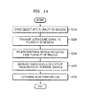
- FIG. 14 is a flowchart of a method of generating an ultrasound image, according to another exemplary embodiment.
- the method according to another exemplary embodiment includes operations performed in series by the ultrasound apparatus 200 illustrated in FIG. 9 . Accordingly, although not mentioned particularly below, the descriptions provided above in relation to the ultrasound apparatus 200 illustrated in FIG. 9 may also be applied to the method illustrated in FIG. 14 . It is understood that the method shown in FIG. 14 is not required to be performed by the ultrasound apparatus 200 illustrated in FIG. 9 , and may alternatively be performed by other apparatuses according to other exemplary embodiments.
- the ultrasound apparatus 200 divides an image of an object into a plurality of regions.
- the ultrasound apparatus 200 may divide a portion of the object into a plurality of regions.
- the ultrasound apparatus 200 transmits an ultrasound signal to the plurality of regions.
- the ultrasound apparatus 200 receives response signals reflected from the plurality of regions.
- the ultrasound apparatus 200 measures power levels or Doppler frequencies of the response signals reflected from the plurality of regions.
- the ultrasound apparatus 200 determines a monitoring region from among the plurality of regions by using the power levels or the Doppler frequencies of the response signals.
- the ultrasound apparatus 200 may adjust a region of interest in such a way that the monitoring region is included in the region of interest, or may adjust a range gate in such a way that the range gate is located in the monitoring region.
- Exemplary embodiments of the present disclosure can be written as computer programs and can be implemented in general-use digital computers that execute the programs using a computer-readable recording medium.
- Examples of the computer-readable recording medium include magnetic storage media (e.g., ROM, floppy disks, hard disks, etc.), optical recording media (e.g., CD-ROMs or DVDs), etc.
- magnetic storage media e.g., ROM, floppy disks, hard disks, etc.
- optical recording media e.g., CD-ROMs or DVDs
Abstract
Description
- This application claims the benefit of
U.S. Provisional Patent Application No. 61/600,062, filed on February 17, 2012 10-2012-0075171, filed on July 10, 2012 - The present disclosure relates to a method and apparatus for generating an ultrasound image and, more particularly, to a method and apparatus for generating a Doppler image of an object.
- Ultrasound apparatuses are used to monitor the internal structure of an organic body. Ultrasound apparatuses are non-invasive test devices and show structural details, tissues, and fluidic flows in the body.
- An ultrasound apparatus may display the flow of blood or movement of tissues as a color Doppler image or a spectral Doppler image, and a user may view the color Doppler image or the spectral Doppler image to check the motion of heart valves, a blood velocity or a blood flow rate in blood vessels, or the like.
- Since the color Doppler image and the spectral Doppler image include information about a velocity magnitude and a velocity direction of a blood flow or tissues, a method of accurately measuring the information is required.
- The present disclosure provides an ultrasound apparatus and a method of generating an ultrasound image which are capable of accurately measuring vector information of an object.
- The present disclosure also provides an ultrasound apparatus and a method of generating an ultrasound image which are capable of providing a reliable color Doppler image or a reliable spectral Doppler image to a user.
- According to the present invention there is provided an apparatus and method as set forth in the appended claims. Other features of the invention will be apparent from the dependent claims, and the description which follows.
- According to an aspect of an exemplary embodiment, there is provided a method of generating an ultrasound image, the method including transmitting an ultrasound signal to a predetermined point included in an object and receiving at least three response signals reflected from the predetermined point; extracting a plurality of response signal pairs by combining the received at least three response signals two-by-two; obtaining a plurality of pieces of prediction vector information, each of the pieces of prediction vector information indicating a prediction velocity magnitude and a prediction velocity direction of the predetermined point, based on reception angles and Doppler frequencies of the response signals included in the plurality of response signal pairs; and determining vector information indicating a velocity magnitude and a velocity direction of the predetermined point, based on the plurality of pieces of prediction vector information.
- The determining of the vector information may include determining the vector information based on a linear vector sum of the plurality of pieces of prediction vector information.
- The determining of the vector information may include determining any one of the plurality of prediction velocity directions included in the plurality of pieces of prediction vector information, as the velocity direction of the predetermined point; and determining a linear sum of the plurality of prediction velocity magnitudes included in the plurality of pieces of prediction vector information, as the velocity magnitude of the predetermined point.
- The method may further include determining vector information of a plurality of additional points located within a preset distance from the predetermined point.
- The determining of the vector information may include compensating for the velocity direction of the predetermined point by applying a smoothing filter to velocity directions of the plurality of additional points; and determining the compensated velocity direction as the velocity direction of the predetermined point.
- The determining of the vector information may include compensating for the velocity magnitude of the predetermined point by applying a smoothing filter to velocity magnitudes of the plurality of additional points; and determining the compensated velocity magnitude as the velocity magnitude of the predetermined point.
- The transmitting of the ultrasound signal may include transmitting the ultrasound signal a plurality of times and receiving each of the at least three response signals a plurality of times, a plurality of the same received response signal forming ensemble signals for the respective response signal, and the obtaining of the plurality of pieces of prediction vector information may include obtaining a Doppler frequency of each response signal included in the plurality of response signal pairs by using autocorrelation between the ensemble signals of the response signals.
- According to another aspect of an exemplary embodiment, there is provided a method of generating an ultrasound image, the method including transmitting an ultrasound signal to a point included in an object and receiving a response signal reflected from the point; determining vector information indicating a velocity magnitude of the point, based on a reception angle and a Doppler frequency of the response signal; and displaying a color Doppler image of the object by mapping the velocity magnitude of the point to a color scale.
- The method may further include determining vector information including a velocity direction of a plurality of points included in the object; estimating an overall velocity direction of the object by using the velocity directions of the plurality of points; and displaying the color Doppler image of the object by mapping angle differences between the velocity directions of the plurality of points and the overall velocity direction of the object to a color scale.
- The method may further include determining vector information including a velocity magnitude of a plurality of points included in the object, and the displaying of the color Doppler image of the object may include mapping a velocity magnitude of a point having a first velocity direction component, from among the plurality of points, to a first color and mapping a velocity magnitude of a point having a second velocity direction component opposite to the first velocity direction component, from among the plurality of points, to a second color.
- According to another aspect of an exemplary embodiment, there is provided a method of generating an ultrasound image, the method including dividing an object into a plurality of regions; transmitting an ultrasound signal to the plurality of regions and receiving response signals reflected from the plurality of regions; measuring power levels or Doppler frequencies of the received response signals; and determining a monitoring region from among the plurality of regions by using the power levels or the Doppler frequencies of the received response signals.
- The determining of the monitoring region may include arbitrarily setting an initial region from among the plurality of regions; and determining one of the regions reflecting response signals having Doppler frequencies in a first predetermined range, which is closest to the initial region, as the monitoring region.
- The determining of the monitoring region may include determining one of the regions reflecting a response signal having a Doppler frequency in a second predetermined range, as the monitoring region.
- The determining of the monitoring region may include arbitrarily setting an initial region from among the plurality of regions; and determining one of the regions reflecting response signals having power levels in a third predetermined range, which is closest to the initial region, as the monitoring region.
- The determining of the monitoring region may include determining one of the regions reflecting a response signal having a power level in a fourth predetermined range, as the monitoring region.
- The determining of the monitoring region may include determining one of the regions reflecting a response signal having a power level in a fifth predetermined range from among the response signals that pass through a clutter filter, as the monitoring region.
- The method may further include adjusting a region of interest in such a way that the monitoring region is included in the region of interest.
- The method may further include adjusting a range gate in such a way that the range gate is located in the monitoring region.
- The method may further include measuring power levels or Doppler frequencies of response signals reflected from a plurality of the regions located within a preset distance from the monitoring region; obtaining a modeled line by applying a fitting method to the power levels or the Doppler frequencies of the response signals reflected from the plurality of regions; determining a blood vessel direction of the object based on the obtained modeled line; and adjusting a steering angle of the ultrasound signal in such a way that an angle between the blood vessel direction and an incident direction of the ultrasound signal transmitted to the plurality of regions is a predetermined angle.
- According to another aspect of an exemplary embodiment, there is provided an ultrasound apparatus including a probe which transmits an ultrasound signal to a predetermined point included in an object and receives at least three response signals reflected from the predetermined point; an extraction unit which extracts a plurality of response signal pairs by combining the received at least three response signals two-by-two; a vector information obtaining unit which obtains a plurality of pieces of prediction vector information, each of the pieces of prediction vector information indicating a prediction velocity magnitude and a prediction velocity direction of the predetermined point, based on reception angles and Doppler frequencies of response signals included in the plurality of response signal pairs; and a vector information determination unit which determines vector information indicating a velocity magnitude and a velocity direction of the predetermined point, based on the plurality of pieces of prediction vector information.
- The vector information determination unit may determine the vector information by using a linear vector sum of the plurality of pieces of prediction vector information.
- The vector information determination unit may determine any one of the plurality of prediction velocity directions included in the plurality of pieces of prediction vector information, as the velocity direction of the predetermined point, and may determine a linear sum of the plurality of prediction velocity magnitudes included in the plurality of pieces of prediction vector information, as the velocity magnitude of the predetermined point.
- The vector information determination unit may determine vector information of a plurality of additional points located within a preset distance from the predetermined point.
- The vector information determination unit may compensate for the velocity direction of the predetermined point by applying a smoothing filter to velocity directions of the plurality of additional points, and may determine the compensated velocity direction as the velocity direction of the predetermined point.
- The vector information determination unit may compensate for the velocity magnitude of the predetermined point by applying a smoothing filter to velocity magnitudes of the plurality of additional points, and may determine the compensated velocity magnitude as the velocity magnitude of the predetermined point.
- The probe may transmit the ultrasound signal a plurality of times and receive each of the at least three response signals a plurality of times, a plurality of the same received response signal forming ensemble signals for the respective response signal, and the vector information obtaining unit may obtain a Doppler frequency of each response signal included in the plurality of response signal pairs by using autocorrelation between the ensemble signals of the response signals.
- According to another aspect of an exemplary embodiment, there is provided an ultrasound apparatus including a probe which transmits an ultrasound signal to a point included in an object and receives a response signal reflected from the point; a vector information determination unit which determines vector information indicating a velocity magnitude of the point, based on a reception angle and a Doppler frequency of the response signal; and a display unit which displays a color Doppler image of the object by mapping the velocity magnitude of the point to a color scale.
- The vector information determination unit may determine vector information including velocity directions of a plurality of points included in the object and estimates an overall velocity direction of the object by using the velocity directions of the plurality of points, and the display unit may display the color Doppler image of the object by mapping angle differences between the velocity directions of the plurality of points and the overall velocity direction of the object to a color scale.
- The vector information determination unit may determine vector information including a vector magnitude of a plurality of points included in the object, and the display unit may map a velocity magnitude of a point having a first velocity direction component, from among the plurality of points, to a first color and may map a velocity magnitude of a point having a second velocity direction component opposite to the first velocity direction component, from among the plurality of points, to a second color.
- According to another aspect of an exemplary embodiment, there is provided an ultrasound apparatus including a region dividing unit which divides an object into a plurality of regions; a probe which transmits an ultrasound signal to the plurality of regions and receives response signals reflected from the plurality of regions; a measurement unit which measures power levels or Doppler frequencies of the received response signals; and a control unit which determines a monitoring region from among the plurality of regions by using the power levels or the Doppler frequencies of the received response signals.
- The control unit arbitrarily may set an initial region from among the plurality of regions, and may determine one of the regions reflecting response signals having Doppler frequencies in a first predetermined range, which is closest to the initial region, as the monitoring region.
- The control unit may determine one of the regions reflecting a response signal having a Doppler frequency in a second predetermined range, as the monitoring region.
- The control unit may arbitrarily set an initial region from among the plurality of regions, and may determine one of the regions reflecting response signals having power levels in a third predetermined range, which is closest to the initial region, as the monitoring region.
- The control unit may determine one of the regions reflecting a response signal having a power level in a fourth predetermined range, as the monitoring region.
- The control unit may determine one of the regions reflecting a response signal having a power level in a fifth predetermined range from among the response signals that pass through a clutter filter, as the monitoring region.
- The control unit may adjust a region of interest in such a way that the monitoring region is included in the region of interest.
- The control unit may adjust a range gate in such a way that the range gate is located in the monitoring region.
- The measurement unit may measure power levels or Doppler frequencies of response signals reflected from a plurality of the regions located within a preset distance from the monitoring region, and the control unit may determine a blood vessel direction of the object based on a modeled line obtained by applying a fitting method to the power levels or the Doppler frequencies of the response signals reflected from the plurality of regions, and may adjust a steering angle of the ultrasound signal in such a way that an angle between the blood vessel direction and an incident direction of the ultrasound signal transmitted to the plurality of regions is a predetermined angle.
- According to another aspect of an exemplary embodiment, there is provided a non-transitory computer-readable recording medium having recorded thereon a computer program for executing the method according to exemplary embodiments.
- According to another aspect of an exemplary embodiment, there is provided an ultrasound apparatus including a probe which transmits an ultrasound signal to a point of an object and receives a plurality of response signals reflected back from the point, and a vector information determiner which determines a velocity direction and a velocity magnitude of the point based on the response signals, wherein, for each of the plurality of response signals, an angle between a reflection direction of the response signal and a velocity direction of the point is less than or greater than 90°.
- The above and other features and advantages of the present disclosure will become more apparent by describing in detail exemplary embodiments thereof with reference to the attached drawings in which:
-
FIG. 1 is a schematic diagram for describing a general method of obtaining a velocity magnitude of an object; -
FIG. 2 is a block diagram of an ultrasound apparatus according to an exemplary embodiment; -
FIG. 3 is a schematic diagram showing an ultrasound signal being transmitted to a predetermined point of an object and response signals being received from the predetermined point using the ultrasound apparatus illustrated inFIG. 2 ; -
FIG. 4 is a schematic diagram for describing a method of obtaining vector information of the predetermined point of the object using the ultrasound apparatus illustrated inFIG. 2 ; -
FIG. 5A is a schematic diagram showing vector information of a plurality of points of the object obtained using the ultrasound apparatus illustrated inFIG. 2 ; -
FIG. 5B is a schematic diagram showing a result of applying a smoothing filter to the vector information illustrated inFIG. 5A ; -
FIG. 6 is a block diagram of an ultrasound apparatus according to another exemplary embodiment; -
FIGS. 7A and 7B are color Doppler images in which vector information of a plurality of points of an object is mapped to a color scale; -
FIG. 8 is a flowchart of a method of generating an ultrasound image, according to an exemplary embodiment; -
FIG. 9 is a block diagram of an ultrasound apparatus according to another exemplary embodiment; -
FIG. 10 is a schematic diagram for describing a method of determining a monitoring region from among a plurality of regions of an object, using the ultrasound apparatus illustrated inFIG. 9 ; -
FIG. 11 is a schematic diagram for describing another method of determining a monitoring region from among a plurality of regions of an object, using the ultrasound apparatus illustrated inFIG. 9 ; -
FIG. 12 is a schematic diagram for describing a method of determining a location of a blood vessel included in an object, using the ultrasound apparatus illustrated inFIG. 9 ; -
FIG. 13 is a schematic diagram for describing a method of adjusting a steering angle of an ultrasound signal, using the ultrasound apparatus illustrated inFIG. 9 ; and -
FIG. 14 is a flowchart of a method of generating an ultrasound image, according to another exemplary embodiment. - The present disclosure will now be described more fully with reference to the accompanying drawings, in which exemplary embodiments are shown. The exemplary embodiments may, however, be embodied in many different forms and should not be construed as being limited to the exemplary embodiments set forth herein; rather, these exemplary embodiments are provided so that this disclosure will be thorough and complete, and will fully convey the concept of the exemplary embodiments to one of ordinary skill in the art. Like reference numerals in the drawings denote like elements.
- The term "unit" in the exemplary embodiments of the present disclosure may refer to a software component or a hardware component, such as a field-programmable gate array (FPGA) or an application-specific integrated circuit (ASIC), that performs a specific function. However, the term "unit" is not limited to software or hardware. The "unit" may be formed so as to be stored in an addressable storage medium, or may be formed so as to operate one or more processors. Thus, for example, the term "unit" may refer to components such as software components, object-oriented software components, class components, and task components, processes, functions, properties, procedures, subroutines, segments of program codes, drivers, firmware, micro codes, circuits, data, databases, data structures, tables, arrays, and parameters. Functions provided by elements and "units" may be combined in a smaller number of elements and "units" or may be separated into additional elements and "units".
- According to exemplary embodiments, the term 'vector information' refers to a vector value indicating a velocity magnitude and a velocity direction, and the term 'velocity magnitude' refers to a scalar value not indicating a direction of a velocity but indicating only a magnitude of the velocity. According to exemplary embodiments, the term 'velocity direction' refers to a direction in which a certain point of an object moves at an arbitrary time.
-
FIG. 1 is a schematic diagram for describing a general method of obtaining a velocity magnitude of anobject 20. - In the present disclosure, an 'object' refers to a certain body part of which an ultrasound image is to be obtained, e.g., tissue, blood, or an organ.
- A predetermined point P (22) of the object moves at a velocity magnitude v and in a velocity direction A. A
probe 10 of an ultrasound apparatus transmits an ultrasound signal having a frequency f0 to thepredetermined point P 22 and receives a response signal reflected from the predetermined point P (22). Based on the Doppler effect, a frequency of the response signal varies according to the velocity magnitude v of the predetermined point P (22) and an angle θ between an incident direction of the ultrasound signal and the velocity direction A of the predetermined point P (22), and a difference between the frequency of the ultrasound signal transmitted to the predetermined point P (22) and the frequency of the response signal is referred to as a Doppler frequency. Also, a signal having the Doppler frequency is referred to as a Doppler signal. The velocity magnitude v of the predetermined point P (22) may be obtained by using the Doppler frequency. - If an angle between a velocity direction of each point and an incident direction of an ultrasound signal transmitted to an object is 0°, a velocity magnitude of the point may be accurately measured. However, a velocity magnitude of a point that is moving in another direction may not be accurately measured. In particular, if an angle between a velocity direction of each point and an incident direction of an ultrasound signal transmitted to an object is 90°, since a Doppler frequency is 0 Hz, a velocity magnitude of the point is measured as 0.
-
FIG. 2 is a block diagram of anultrasound apparatus 100 according to an exemplary embodiment. - Referring to
FIG. 2 , theultrasound apparatus 100 according to the exemplary embodiment includes aprobe 110, anextraction unit 120, a vectorinformation obtaining unit 130, and a vector information determination unit 140 (also referred to as vector information determiner). Theextraction unit 120, the vectorinformation obtaining unit 130, and the vectorinformation determination unit 140 may be formed as microprocessors, although are not limited thereto. - The
probe 110 includes a plurality of piezoelectric elements, and transmits an ultrasound signal to a predetermined point P (22) of an object and receives at least three response signals reflected from the predetermined point P (22). Each of the at least three response signals may have a Doppler frequency and a reception angle that is an incident angle from theprobe 110. -
FIG. 3 is a schematic diagram showing an ultrasound signal T being transmitted to a predetermined point P (22) of an object and response signals R1, R2, and R3 being received from the predetermined point P (22), using theultrasound apparatus 100 illustrated inFIG. 2 . Referring toFIG. 3 , theprobe 110 transmits the ultrasound signal T to the predetermined point P (22) in ablood vessel 24 of the object and receives the response signals R1, R2, and R3 reflected from the predetermined point P (22). The response signals R1, R2, and R3 respectively have reception angles θ1, θ2, and θ3. - The
probe 110 may transmit the ultrasound signal T to the predetermined point P (22) of the object a plurality of times and may receive each of the at least three response signals reflected from the predetermined point P (22) a plurality of times. For example, if the three response signals include the response signals R1, R2, and R3, theprobe 110 receives each of the response signals R1, R2, and R3 a plurality of times. A plurality of response signals R1, a plurality of response signals R2, and a plurality of response signals R3 are referred to as ensemble signals. That is, ensemble signals refer to a plurality of response signals received at the same reception angle. By receiving a response signal a plurality of times, the reliability of data obtained by using the response signal may be improved. - The
extraction unit 120 extracts a plurality of response signal pairs by combining the at least three response signals received by theprobe 110 two-by-two. If n response signals are received, a certain number of response signal pairs may be extracted.. The certain number may be nC2 (nC2 = {n*(n-1)} / (2*1)). - For example, if the
probe 110 receives the response signals R1, R2, and R3, a response signal pair R12 may be extracted by combining the response signals R1 and R2, a response signal pair R13 may be extracted by combining the response signals R1 and R3, and a response signal pair R23 may be extracted by combining the response signals R2 and R3. - The vector
information obtaining unit 130 obtains a plurality of pieces of prediction vector information indicating a prediction velocity magnitude and a prediction velocity direction of the predetermined point P (22), based on reception angles and Doppler frequencies of response signals included in the plurality of response signal pairs. The vectorinformation obtaining unit 130 may obtain a Doppler frequency of each response signal included in the plurality of response signal pairs by using autocorrelation between ensemble signals of the response signal. - Many different methods of obtaining vector information indicating a velocity magnitude and a velocity direction of a predetermined point by using Doppler frequencies and reception angles of two response signals may be used according to exemplary embodiments, and a detailed description thereof is not provided here.
- The vector
information determination unit 140 determines vector information indicating a velocity magnitude and a velocity direction of the predetermined point P (22) of the object, by using the plurality of pieces of prediction vector information. - In a conventional ultrasound apparatus using a vector Doppler technique, vector information of a predetermined point of an object is obtained by using only two response signals reflected from the predetermined point. However, if an angle between a reflection direction of any one response signal and a velocity direction of the predetermined point is close to 90°, accurate vector information may not be obtained. On the other hand, by using the
ultrasound apparatus 100 according to exemplary embodiments or by using a method of generating an ultrasound image according to exemplary embodiments, since vector information of the predetermined point P (22) of the object is obtained by using at least three response signals reflected from the predetermined point P (22), accurate vector information may be obtained. -
FIG. 4 is a schematic diagram for describing a method of obtaining vector information V of the predetermined point P (22) of the object, using theultrasound apparatus 100 illustrated inFIG. 2 . -
FIG. 4 shows three pieces of prediction vector information V12, V23, and V13 obtained by using response signal pairs of three response signals reflected from the predetermined point P (22) in theblood vessel 24. - The vector
information determination unit 140 may obtain vector information V of the predetermined point P (22) by using a linear vector sum of the pieces of prediction vector information V12, V23, and V13. - That is, the vector
information determination unit 140 may obtain the vector information V of the predetermined point P (22) by usingEquation 1. - [Equation 1]
-

- If all of a, b, and c are set as 1, the vector information V may be a simple vector sum of the pieces of prediction vector information V12, V23, and V13. If all of a, b, and c are set as 1/3, the vector information V may be an average of the pieces of prediction vector information V12, V23, and V13. Alternatively, a, b, and c may be set as different real numbers to apply a weight to a certain piece of prediction vector information.
- A prediction velocity direction included in each piece of prediction vector information is not significantly different from an actual velocity direction of the predetermined point P (22), and a significant difference does not exist between prediction velocity directions.
- Accordingly, the vector
information determination unit 140 may determine any one of the prediction velocity directions included in the pieces of prediction vector information as being the velocity direction of the predetermined point P (22), and may determine a linear sum of prediction velocity magnitudes included in the pieces of prediction vector information as being the velocity magnitude of the predetermined point P (22). The velocity magnitude of the predetermined point P (22) may be obtained by using Equation 2. According to this technique, the amount of calculations for obtaining the vector information of the predetermined point P (22) may be reduced. - [Equation 2]
-

-
FIG. 5A is a schematic diagram showing vector information of a plurality of points including the predetermined point P (22), obtained using the ultrasound apparatus illustrated inFIG. 2 .FIG. 5B is a schematic diagram showing a result of applying a smoothing filter to the vector information illustrated inFIG. 5A . - If a response signal reflected from the predetermined point P (22) has noise, vector information of the predetermined point P (22) may not be accurately obtained. Since the predetermined point P (22) of the object and peripheral points of the predetermined point P (22) have similar velocity magnitudes and velocity directions, accurate vector information may be obtained in consideration of the velocity magnitudes and the velocity directions of the peripheral points as well as the velocity magnitude and the velocity direction of the predetermined point P (22).
- The vector
information determination unit 140 determines vector information of each of a plurality of points located within a preset distance from the predetermined point P (22). In more detail, theprobe 110 transmits an ultrasound signal to the plurality of points and receives at least three response signals reflected from each of the plurality of points. Theextraction unit 120 extracts a plurality of response signal pairs with respect to each of the plurality of points, and the vectorinformation obtaining unit 130 obtains a plurality of pieces of prediction vector information of each of the plurality of points by using the plurality of response signal pairs. The vectorinformation determination unit 140 determines vector information of the plurality of points by using the plurality of pieces of prediction vector information. The vector information of the plurality of points is represented by arrows inFIG. 5A . It is understood that the vector information of the plurality of points is not limited to being represented by the arrows shown inFIG. 5A , and may be represented in other ways as well. - A smoothing filter is commonly used in the fields of, for example, statistics and image processing, and is a technology for smoothing a data set to extract a pattern of the data set and to remove noise. For example, the smoothing filter may apply different weights to data of a plurality of points including a certain point so as to calculate their average and may determine the calculated average as data of the certain point.
-
FIG. 5B shows a result of applying a smoothing filter to the velocity magnitudes and the velocity directions of the plurality of points illustrated inFIG. 5A . As shown inFIG. 5B , by using the smoothing filter, the velocity magnitude and the velocity direction of the predetermined point P (22), which were significantly different from the velocity magnitudes and the velocity directions of the peripheral points before using the smoothing filter (as shown inFIG. 5A ), are compensated. - The vector
information determination unit 140 may compensate for only the velocity direction of the predetermined point P (22) by applying a smoothing filter to velocity directions of the plurality of points, or may compensate for only the velocity magnitude of the predetermined point P (22) by applying a smoothing filter to velocity magnitudes of the plurality of points. -
FIG. 6 is a block diagram of anultrasound apparatus 100 according to another exemplary embodiment of the present invention. Theultrasound apparatus 100 according to the exemplary embodiment shown inFIG. 6 may further include adisplay unit 150. - The
ultrasound apparatus 100 includes thedisplay unit 150 which may display a color Doppler image of an object to a user. Thedisplay unit 150 may display the color Doppler image of the object by mapping velocity magnitudes of a plurality of points of the object to a color scale. It is understood that thedisplay unit 150 is not required to display a color image, and may also display other types of images, e.g., black and white images, according to other exemplary embodiments. - Also, the
ultrasound apparatus 100 may obtain vector information of a predetermined point of the object by using a method of obtaining the vector information of the predetermined point, and may display the color Doppler image of the object by mapping a velocity magnitude of the predetermined point to a color scale. - In more detail, the
probe 110 transmits an ultrasound signal to a predetermined point included in an object and receives a response signal reflected from the predetermined point. The vectorinformation determination unit 140 determines vector information indicating a velocity magnitude and a velocity direction of the predetermined point, based on a reception angle and a Doppler frequency of the response signal. The vectorinformation determination unit 140 may determine the vector information of the predetermined point based on reception angles and Doppler frequencies of two response signals. Thedisplay unit 150 may display a color Doppler image of the object by mapping the velocity magnitude of the predetermined point to a color scale. -
FIGS. 7A and 7B are color Doppler images in which vector information of a plurality of points of an object is mapped to acolor scale 25. - The
display unit 150 may display the color Doppler image of the object by mapping velocity magnitudes of the plurality of points to predetermined colors of thecolor scale 25. As such, a user may instinctively and easily check movement of, for example, blood in a blood vessel. - If only velocity magnitudes of the plurality of points are mapped to the
color scale 25, two points having opposite velocity directions but having the same velocity magnitude may be mapped to the same color. Accordingly, the color Doppler image should be formed in consideration of velocity magnitudes and velocity directions of the plurality of points. - From among the plurality of points, the
display unit 150 of theultrasound apparatus 100 may map a velocity magnitude of a point having a first velocity direction component to a first color, and may map a velocity magnitude of a point having a second velocity direction component opposite to the first velocity direction component to a second color, as illustrated inFIG. 7A . Thecolor scale 25 ofFIG. 7A include colors corresponding to velocity magnitudes from 0 to -1, or from 0 to 1. That is, points having avelocity direction ① are mapped to the first color (corresponding to a part above thevelocity magnitude 0 in thecolor scale 25 ofFIG. 7A ), and points having a velocity direction ② are mapped to the second color (corresponding to a part below thevelocity magnitude 0 in thecolor scale 25 ofFIG. 7A ). As such, a user may easily check blood flow and may easily identify different types of blood flow, such as backflow. - The vector
information determination unit 140 may estimate an overall velocity direction of the object by using the velocity directions of the plurality of points. For example, the vectorinformation determination unit 140 may estimate an overall velocity direction of the object by using a vector sum of the vector information of the plurality of points. - The
display unit 150 may display the color Doppler image of the object by mapping angle differences between the velocity directions of the plurality of points and the overall velocity direction of the object to thecolor scale 25. As such, a user may easily check blood flow and may easily identify different types of blood flow, such as turbulent flow or backflow. - The
display unit 150 may display the color Doppler image of the object by mapping velocity magnitudes of the plurality of points and angle differences between the velocity directions of the plurality of points and the overall velocity direction of the object to thecolor scale 25, as illustrated inFIG. 7B . That is, referring toFIG. 7B , points having different velocity magnitudes and velocity directions are mapped to different colors. Thecircular color scale 25 ofFIG. 7B includes colors corresponding to increasing or decreasing velocity magnitudes as indicated by the relative positions of the colors from a center of thecircular color scale 25 toward a circumference of thecircular color scale 25, and includes colors corresponding to angle differences between the velocity directions of the plurality of points and the overall velocity direction of the object as indicated by the relative angular positions of the colors within thecircular color scale 25. -
FIG. 8 is a flowchart of a method of generating an ultrasound image, according to an exemplary embodiment. Referring toFIG. 8 , the method according to the exemplary embodiment includes operations performed in series by theultrasound apparatus 100 illustrated inFIG. 2 . Accordingly, although not mentioned particularly below, the descriptions provided above in relation to theultrasound apparatus 100 illustrated inFIG. 2 may also be applied to the method illustrated inFIG. 8 . It is understood that the method shown inFIG. 8 is not required to be performed by theultrasound apparatus 100 illustrated inFIG. 2 , and may alternatively be performed by other apparatuses according to other exemplary embodiments. - In operation S110, the
ultrasound apparatus 100 transmits an ultrasound signal to the predetermined point P (22) included in the object. - In operation S120, the
ultrasound apparatus 100 receives at least three response signals reflected from the predetermined point P (22). Each of the at least three response signals has a Doppler frequency and a reception angle. - In operation S130, the
ultrasound apparatus 100 extracts a plurality of response signal pairs by combining the at least three response signals two-by-two. If theultrasound apparatus 100 receives n response signals, a certain number of response signal pairs may be extracted.. The certain number may be nC2 (nC2 = {n*(n-1)} / (2*1)). - In operation S140, the
ultrasound apparatus 100 obtains a plurality of pieces of prediction vector information by using the plurality of response signal pairs. The plurality of pieces of prediction vector information includes a prediction velocity magnitude and a prediction velocity direction of the predetermined point P (22). - In operation S150, the
ultrasound apparatus 100 determines vector information indicating a velocity magnitude and a velocity direction of the predetermined point P (22) by using the plurality of pieces of prediction vector information. -
FIG. 9 is a block diagram of anultrasound apparatus 200 according to another exemplary embodiment. - The
ultrasound apparatus 200 according to the exemplary embodiment shown inFIG. 9 locates a region of interest in an image generated by a color Doppler apparatus and a range gate in an image generated by a spectral Doppler apparatus accurately on a region of an object to be measured, and adjusts a steering angle of an ultrasound signal in such a way that an angle between a velocity direction of the region to be measured and an incident direction of the ultrasound signal transmitted to the object is not 90°. - Referring to
FIG. 9 , theultrasound apparatus 200 according to the exemplary embodiment includes aprobe 210, aregion dividing unit 220, ameasurement unit 230, and acontrol unit 240. Theregion dividing unit 220 and thecontrol unit 240 may be formed as microprocessors, although are not limited thereto. - Initially, the
region dividing unit 220 divides the object into a plurality of regions. Theregion dividing unit 220 may divide only a portion of the object into a plurality of regions. - The
probe 210 transmits an ultrasound signal to the plurality of regions and receives response signals reflected from the plurality of regions. - The
measurement unit 230 measures power levels or Doppler frequencies of the received response signals. - The
control unit 240 determines a monitoring region from among the plurality of regions by using the power levels or the Doppler frequencies of the response signals. - When a user desires to measure movement of blood in a blood vessel, the region of interest should be adjusted to include blood in the blood vessel and the range gate should be adjusted to be located in blood in the blood vessel. However, if the user manually adjusts the region of interest and the range gate, an inaccurate Doppler image may be generated.
- Accordingly, when a user desires to measure movement of blood in a blood vessel, the
ultrasound apparatus 200 automatically adjusts the monitoring region of theultrasound apparatus 200 to be located in blood in the blood vessel and correspondingly adjusts the region of interest or the range gate. -
FIGS. 10 and 11 are schematic diagrams for describing methods of determining amonitoring region 36 from among a plurality ofregions 28 of anobject 20, using theultrasound apparatus 200 illustrated inFIG. 9 . According to this example, a user desires to monitor movement of blood in ablood vessel 24. It is understood that many other types of objects and flows may also be monitored. -
FIGS. 10 and 11 show theobject 20 includingtissues 26 and theblood vessel 24, and a portion of theobject 20 is divided into the plurality ofregions 28. - In
FIG. 10 , thecontrol unit 240 arbitrarily sets aninitial region 32 from among the plurality ofregions 28. - The
measurement unit 230 measures power levels or Doppler frequencies of response signals reflected from the plurality ofregions 28. - In general, power levels of response signals reflected from the
tissues 26 are higher than those of response signals reflected from blood, and a Doppler frequency of a response signal reflected from thetissue 26 is less than that of a response signal reflected from blood. - The
control unit 240 selectsregions 34 reflecting response signals having Doppler frequencies in a first predetermined range and determines one of theregions 34, which is the closest to theinitial region 32 set by thecontrol unit 240, as themonitoring region 36. The first predetermined range may be a Doppler frequency range equal to or greater than a preset value and equal to or less than the highest Doppler frequency from among the Doppler frequencies of the response signals. Since theregions 34 reflecting response signals having Doppler frequencies greater than the preset value are mostly distributed in a region where blood flows in theblood vessel 24, thecontrol unit 240 determines one of theregions 34, which is the closest to theinitial region 32, as themonitoring region 36. However, the first predetermined range may vary within a range that is well known to one of ordinary skill in the art. - Referring to
FIG. 11 , thecontrol unit 240 may not set an initial region and may determine a region reflecting a response signal having a Doppler frequency in a second predetermined range from among the Doppler frequencies of the received response signals, as themonitoring region 36. In this case, the second predetermined range may include the highest Doppler frequency from among the Doppler frequencies of the response signals, and may vary within a range that is well known to one of ordinary skill in the art. - Also, the
control unit 240 may selectregions 34 reflecting response signals having a power level in a third predetermined range and may determine one of theregions 34, which is the closest to theinitial region 32 set by thecontrol unit 240, as themonitoring region 36. The third predetermined range may be a power level range greater than 0 and equal to or less than a preset value. Since theregions 34 reflecting response signals having a power level less than the preset value are mostly distributed in a region where blood flows in theblood vessel 24, thecontrol unit 240 determines one of theregions 34, which is the closest to theinitial region 32, as themonitoring region 36. However, the third predetermined range may vary within a range that is well known to one of ordinary skill in the art. - Furthermore, as illustrated in
FIG. 11 , thecontrol unit 240 may not set an initial region and may determine a region reflecting a response signal having a power level in a fourth predetermined range, as themonitoring region 36. In this case, the fourth predetermined range may include the lowest power level from among the power levels of the response signals, and may vary within a range that is well known to one of ordinary skill in the art. - As described above, the response signals reflected from the plurality of
regions 28 include the response signals reflected from thetissues 26 and the response signals reflected from blood. The response signals reflected from thetissues 26 may be removed by applying a clutter filter to the received response signals. As such, the response signals reflected from thetissues 26, which have power levels relatively higher than those of response signals reflected from blood, may be removed. In this case, thecontrol unit 240 may determine a region reflecting a response signal having a power level in a fifth predetermined range from among the response signals that pass through the clutter filter, as themonitoring region 36. The fifth predetermined range may include the highest power level from among the power levels of the response signals that pass through the clutter filter, and may vary within a range that is well known to one of ordinary skill in the art. - In the color Doppler apparatus, the
control unit 240 may adjust the region of interest in such a way that themonitoring region 36 is included in the region of interest. In the spectral Doppler apparatus, thecontrol unit 240 may adjust the range gate in such a way that the range gate is located in themonitoring region 36. - Since the
monitoring region 36 is determined based on power levels or Doppler frequencies of response signals, a user may automatically obtain accurate location information of blood and may obtain an accurate Doppler image. - Although a region corresponding to blood in a blood vessel is determined as a monitoring region in the above description, it will be understood by one of ordinary skill in the art that, due to a simple modification, a region corresponding to tissues or other objects may also be determined as the monitoring region.
- As described above, if an angle between an incident direction of an ultrasound signal transmitted to an object and a velocity direction of the predetermined point P (22) is close to 90°, a velocity magnitude of the predetermined point P (22) may not be easily measured in an accurate fashion. Accordingly, a steering angle of the ultrasound signal should be adjusted.
-
FIG. 12 is a schematic diagram for describing a method of determining a location of theblood vessel 24 included in theobject 20, using theultrasound apparatus 200 illustrated inFIG. 9 . - The
measurement unit 230 measures power levels or Doppler frequencies of response signals reflected from a plurality of regions located within a preset distance from themonitoring region 36. - Since Doppler frequencies of response signals reflected from blood are higher than those of response signals reflected from the
tissues 26, if a high-pass filter is applied to the response signals, the response signals that pass through the high-pass filter are mostly distributed along theblood vessel 24 and are scarcely distributed in the other regions. - The
control unit 240 obtains a modeledline 38 by applying a fitting method to the Doppler frequencies of the response signals. The fitting method may include many different type of fitting, e.g., linear fitting or curve fitting, and the modeledline 38 may include a linear line or a curved line. The fitting method is a method of obtaining a line indicating a tendency of data distribution, and is used in statistics. - A location of the modeled
line 38 obtained by applying the fitting method to the Doppler frequencies of the response signals very closely corresponds to the location of theblood vessel 24. Since blood in theblood vessel 24 flows along theblood vessel 24, thecontrol unit 240 adjusts a steering angle of an ultrasound signal transmitted to the plurality of regions in such a way that an angle between the obtained modeledline 38 and an incident direction of the ultrasound signal is a predetermined angle. If the modeledline 38 is a curved line, a direction of a tangent to the curved line may be determined as a direction of theblood vessel 24. Alternatively, thecontrol unit 240 may apply the fitting method to velocity magnitudes of the plurality of regions, which are obtained from the Doppler frequencies of the response signals, based on the concept that blood has velocity magnitudes less than those of thetissues 26. - Also, the
control unit 240 may obtain the modeledline 38 by applying the fitting method to power levels of the response signals. Since power levels of response signals reflected from blood are lower than those of response signals reflected from thetissues 26, thecontrol unit 240 may obtain reciprocals of the power levels of the response signals and may apply a high-pass filter to the reciprocals of the power levels so as to reduce a data distribution of the response signals reflected from thetissues 26. As such, data of the response signals reflected from blood are mostly distributed along theblood vessel 24, and data of the response signals reflected from regions other than blood are reduced. - If the fitting method is applied to the reciprocals of the power levels, the modeled
line 38 illustrated inFIG. 12 may be obtained, and thecontrol unit 240 may adjust the steering angle of the ultrasound signal transmitted to the plurality of regions in such a way that the angle between the obtained modeledline 38 and the incident direction of the ultrasound signal is the predetermined angle. -
FIG. 13 is a schematic diagram for describing a method of adjusting a steering angle of an ultrasound signal, using theultrasound apparatus 200 illustrated inFIG. 9 . - Referring to
FIG. 13 , an angle between the ultrasound signal and the modeledline 38 is θ, and the steering angle of the ultrasound signal is Φ. Thecontrol unit 240 adjusts the steering angle Φ of the ultrasound signal transmitted to theobject 20 in such a way that the angle θ between an incident direction of the ultrasound signal and the modeledline 38 is not 90°. That is, thecontrol unit 240 may adjust the steering angle Φ in such a way that the angle θ between the incident direction of the transmitted ultrasound signal and the modeledline 38 is close to 0°. -
FIG. 14 is a flowchart of a method of generating an ultrasound image, according to another exemplary embodiment. Referring toFIG. 14 , the method according to another exemplary embodiment includes operations performed in series by theultrasound apparatus 200 illustrated inFIG. 9 . Accordingly, although not mentioned particularly below, the descriptions provided above in relation to theultrasound apparatus 200 illustrated inFIG. 9 may also be applied to the method illustrated inFIG. 14 . It is understood that the method shown inFIG. 14 is not required to be performed by theultrasound apparatus 200 illustrated inFIG. 9 , and may alternatively be performed by other apparatuses according to other exemplary embodiments. - In operation S210, the
ultrasound apparatus 200 divides an image of an object into a plurality of regions. Theultrasound apparatus 200 may divide a portion of the object into a plurality of regions. - In operation S220, the
ultrasound apparatus 200 transmits an ultrasound signal to the plurality of regions. - In operation S230, the
ultrasound apparatus 200 receives response signals reflected from the plurality of regions. - In operation S240, the
ultrasound apparatus 200 measures power levels or Doppler frequencies of the response signals reflected from the plurality of regions. - In operation S250, the
ultrasound apparatus 200 determines a monitoring region from among the plurality of regions by using the power levels or the Doppler frequencies of the response signals. - The
ultrasound apparatus 200 may adjust a region of interest in such a way that the monitoring region is included in the region of interest, or may adjust a range gate in such a way that the range gate is located in the monitoring region. - Exemplary embodiments of the present disclosure can be written as computer programs and can be implemented in general-use digital computers that execute the programs using a computer-readable recording medium.
- Examples of the computer-readable recording medium include magnetic storage media (e.g., ROM, floppy disks, hard disks, etc.), optical recording media (e.g., CD-ROMs or DVDs), etc.
- While the present disclosure has been particularly shown and described with reference to exemplary embodiments thereof, it will be understood by those of ordinary skill in the art that various changes in form and details may be made therein without departing from the scope of the present disclosure as defined by the following claims.
- Attention is directed to all papers and documents which are filed concurrently with or previous to this specification in connection with this application and which are open to public inspection with this specification, and the contents of all such papers and documents are incorporated herein by reference.
- All of the features disclosed in this specification (including any accompanying claims, abstract and drawings), and/or all of the steps of any method or process so disclosed, may be combined in any combination, except combinations where at least some of such features and/or steps are mutually exclusive.
- Each feature disclosed in this specification (including any accompanying claims, abstract and drawings) may be replaced by alternative features serving the same, equivalent or similar purpose, unless expressly stated otherwise. Thus, unless expressly stated otherwise, each feature disclosed is one example only of a generic series of equivalent or similar features.
- The invention is not restricted to the details of the foregoing embodiment(s). The invention extends to any novel one, or any novel combination, of the features disclosed in this specification (including any accompanying claims, abstract and drawings), or to any novel one, or any novel combination, of the steps of any method or process so disclosed.
Claims (15)
- A method of generating an ultrasound image, the method comprising:transmitting an ultrasound signal to a predetermined point included in an object and receiving at least three response signals reflected from the predetermined point;extracting a plurality of response signal pairs by combining the received at least three response signals two-by-two;obtaining a plurality of pieces of prediction vector information, each of the plurality of pieces of prediction vector information indicating a prediction velocity magnitude and a prediction velocity direction of the predetermined point, based on reception angles and Doppler frequencies of the response signals included in the plurality of response signal pairs; anddetermining vector information indicating a velocity magnitude and a velocity direction of the predetermined point, based on the plurality of pieces of prediction vector information.
- The method of claim 1, wherein the determining of the vector information comprises determining the vector information based on a linear vector sum of the plurality of pieces of prediction vector information.
- The method of claim 1, wherein the determining of the vector information comprises:determining any one of the plurality of prediction velocity directions included in the plurality of pieces of prediction vector information, as the velocity direction of the predetermined point; anddetermining a linear sum of the plurality of prediction velocity magnitudes included in the plurality of pieces of prediction vector information, as the velocity magnitude of the predetermined point.
- The method of claim 1, further comprising determining vector information of a plurality of additional points located within a preset distance from the predetermined point.
- The method of claim 4, wherein the determining of the vector information comprises:compensating for the velocity direction of the predetermined point by applying a smoothing filter to velocity directions of the plurality of additional points; anddetermining the compensated velocity direction as the velocity direction of the predetermined point.
- The method of claim 4, wherein the determining of the vector information comprises:compensating for the velocity magnitude of the predetermined point by applying a smoothing filter to velocity magnitudes of the plurality of additional points; anddetermining the compensated velocity magnitude as the velocity magnitude of the predetermined point.
- The method of claim 1, wherein:the transmitting of the ultrasound signal comprises transmitting the ultrasound signal a plurality of times and receiving each of the at least three response signals a plurality of times, a plurality of the same received response signal forming ensemble signals for the respective response signal, andthe obtaining of the plurality of pieces of prediction vector information comprises obtaining a Doppler frequency of each response signal included in the plurality of response signal pairs by using autocorrelation between the ensemble signals of the response signals.
- An ultrasound apparatus comprising:a probe which transmits an ultrasound signal to a predetermined point included in an object and receives at least three response signals reflected from the predetermined point;an extraction unit which extracts a plurality of response signal pairs by combining the received at least three response signals two-by-two;a vector information obtaining unit which obtains a plurality of pieces of prediction vector information, each of the pieces of prediction vector information indicating a prediction velocity magnitude and a prediction velocity direction of the predetermined point, based on reception angles and Doppler frequencies of response signals included in the plurality of response signal pairs; anda vector information determination unit which determines vector information indicating a velocity magnitude and a velocity direction of the predetermined point, based on the plurality of pieces of prediction vector information.
- The ultrasound apparatus of claim 8, wherein the vector information determination unit determines the vector information by using a linear vector sum of the plurality of pieces of prediction vector information.
- The ultrasound apparatus of claim 8, wherein the vector information determination unit determines any one of the plurality of prediction velocity directions included in the plurality of pieces of prediction vector information, as the velocity direction of the predetermined point, and determines a linear sum of the plurality of prediction velocity magnitudes included in the plurality of pieces of prediction vector information, as the velocity magnitude of the predetermined point.
- The ultrasound apparatus of claim 8, wherein the vector information determination unit determines vector information of a plurality of additional points located within a preset distance from the predetermined point.
- The ultrasound apparatus of claim 11, wherein the vector information determination unit compensates for the velocity direction of the predetermined point by applying a smoothing filter to velocity directions of the plurality of additional points, and determines the compensated velocity direction as the velocity direction of the predetermined point.
- The ultrasound apparatus of claim 11, wherein the vector information determination unit compensates for the velocity magnitude of the predetermined point by applying a smoothing filter to velocity magnitudes of the plurality of additional points, and determines the compensated velocity magnitude as the velocity magnitude of the predetermined point.
- The ultrasound apparatus of claim 8, wherein the probe transmits the ultrasound signal a plurality of times and receives each of the at least three response signals a plurality of times, a plurality of the same received response signal forming ensemble signals for the respective response signal, and the vector information obtaining unit obtains a Doppler frequency of each response signal included in the plurality of response signal pairs by using autocorrelation between the ensemble signals of the response signal.
- A non-transitory computer-readable recording medium having recorded thereon a computer program for executing the method of any one of claims 1 through 7.
Applications Claiming Priority (2)
| Application Number | Priority Date | Filing Date | Title |
|---|---|---|---|
| US201261600062P | 2012-02-17 | 2012-02-17 | |
| KR1020120075171A KR20130095160A (en) | 2012-02-17 | 2012-07-10 | Ultrasound apparatus and method for generating ultrasound image |
Publications (3)
| Publication Number | Publication Date |
|---|---|
| EP2628449A2 true EP2628449A2 (en) | 2013-08-21 |
| EP2628449A3 EP2628449A3 (en) | 2013-09-04 |
| EP2628449B1 EP2628449B1 (en) | 2020-05-20 |
Family
ID=47826877
Family Applications (1)
| Application Number | Title | Priority Date | Filing Date |
|---|---|---|---|
| EP13155425.5A Active EP2628449B1 (en) | 2012-02-17 | 2013-02-15 | Ultrasound apparatus and method of generating ultrasound image |
Country Status (3)
| Country | Link |
|---|---|
| US (2) | US20130218014A1 (en) |
| EP (1) | EP2628449B1 (en) |
| WO (1) | WO2013122416A1 (en) |
Cited By (2)
| Publication number | Priority date | Publication date | Assignee | Title |
|---|---|---|---|---|
| EP2613176A3 (en) * | 2012-01-09 | 2015-01-28 | Samsung Electronics Co., Ltd. | Ultrasonic device and method of generating ultrasonic image using vector doppler |
| WO2015180069A1 (en) * | 2014-05-28 | 2015-12-03 | 深圳迈瑞生物医疗电子股份有限公司 | Ultrasonic imaging method and system |
Families Citing this family (4)
| Publication number | Priority date | Publication date | Assignee | Title |
|---|---|---|---|---|
| US9877699B2 (en) | 2012-03-26 | 2018-01-30 | Teratech Corporation | Tablet ultrasound system |
| US10667790B2 (en) | 2012-03-26 | 2020-06-02 | Teratech Corporation | Tablet ultrasound system |
| CN114848016A (en) * | 2016-09-30 | 2022-08-05 | 深圳迈瑞生物医疗电子股份有限公司 | Ultrasonic blood flow parameter display method and ultrasonic imaging system thereof |
| KR102322854B1 (en) * | 2017-03-13 | 2021-11-08 | 현대자동차주식회사 | Apparatus and method for detecting moving object using ultrasonic sensor, and alarming system thereof |
Family Cites Families (16)
| Publication number | Priority date | Publication date | Assignee | Title |
|---|---|---|---|---|
| US4800891A (en) * | 1987-11-13 | 1989-01-31 | Siemens Medical Laboratories, Inc. | Doppler velocity processing method and apparatus |
| US5454372A (en) * | 1994-06-17 | 1995-10-03 | Siemens Medical Systems, Inc. | Angle independent doppler in ultrasound imaging |
| US5544655A (en) * | 1994-09-16 | 1996-08-13 | Atlantis Diagnostics International, Llc | Ultrasonic multiline beamforming with interleaved sampling |
| JP3746115B2 (en) * | 1996-10-21 | 2006-02-15 | 株式会社東芝 | Ultrasonic diagnostic equipment |
| CA2290240C (en) * | 1999-11-24 | 2008-03-11 | Stergios Stergiopoulos | High resolution 3d ultrasound imaging system deploying a multi-dimensional array of sensors and method for multi-dimensional beamforming sensor signals |
| US6312385B1 (en) * | 2000-05-01 | 2001-11-06 | Ge Medical Systems Global Technology Company, Llc | Method and apparatus for automatic detection and sizing of cystic objects |
| US6464637B1 (en) * | 2000-06-23 | 2002-10-15 | Koninklijke Philips Electronics N.V. | Automatic flow angle correction by ultrasonic vector |
| WO2002026110A2 (en) * | 2000-09-29 | 2002-04-04 | New Health Sciences, Inc. | Systems and methods for screening for adverse effects of a treatment |
| US6589179B2 (en) * | 2001-11-27 | 2003-07-08 | Koninklijke Philips Electronics Nv | Three-dimensional doppler ultrasonic imaging system and method |
| KR100459616B1 (en) * | 2002-04-17 | 2004-12-04 | 주식회사 메디슨 | Ultrasonic diagnostic apparatus and method for measuring human tissue velocities using doppler effect |
| US6726628B2 (en) * | 2002-05-07 | 2004-04-27 | Dvx, Llc | Angle-independent doppler system for screening |
| US7066888B2 (en) * | 2003-10-29 | 2006-06-27 | Allez Physionix Ltd | Method and apparatus for determining an ultrasound fluid flow centerline |
| US7248725B2 (en) * | 2004-01-07 | 2007-07-24 | Ramot At Tel Avia University Ltd. | Methods and apparatus for analyzing ultrasound images |
| US7215802B2 (en) * | 2004-03-04 | 2007-05-08 | The Cleveland Clinic Foundation | System and method for vascular border detection |
| WO2007085999A1 (en) * | 2006-01-27 | 2007-08-02 | Koninklijke Philips Electronics N.V. | Automatic ultrasonic doppler measurements |
| EP2744416B1 (en) * | 2011-09-30 | 2018-02-28 | Koninklijke Philips N.V. | Ultrasound system with dynamically automated doppler flow settings as a sample volume is moved |
-
2013
- 2013-02-15 EP EP13155425.5A patent/EP2628449B1/en active Active
- 2013-02-15 WO PCT/KR2013/001195 patent/WO2013122416A1/en active Application Filing
- 2013-02-15 US US13/768,627 patent/US20130218014A1/en not_active Abandoned
-
2015
- 2015-12-28 US US14/981,218 patent/US20160106397A1/en not_active Abandoned
Non-Patent Citations (1)
| Title |
|---|
| None |
Cited By (5)
| Publication number | Priority date | Publication date | Assignee | Title |
|---|---|---|---|---|
| EP2613176A3 (en) * | 2012-01-09 | 2015-01-28 | Samsung Electronics Co., Ltd. | Ultrasonic device and method of generating ultrasonic image using vector doppler |
| WO2015180069A1 (en) * | 2014-05-28 | 2015-12-03 | 深圳迈瑞生物医疗电子股份有限公司 | Ultrasonic imaging method and system |
| CN105530870B (en) * | 2014-05-28 | 2019-02-22 | 深圳迈瑞生物医疗电子股份有限公司 | A kind of ultrasonic imaging method and system |
| US11259784B2 (en) | 2014-05-28 | 2022-03-01 | Shenzhen Mindray Bio-Medical Electronics Co., Ltd. | Ultrasound imaging method and system |
| US11826205B2 (en) | 2014-05-28 | 2023-11-28 | Shenzhen Mindray Bio-Medical Electronics Co., Ltd. | Ultrasound imaging method and system |
Also Published As
| Publication number | Publication date |
|---|---|
| US20130218014A1 (en) | 2013-08-22 |
| US20160106397A1 (en) | 2016-04-21 |
| EP2628449B1 (en) | 2020-05-20 |
| WO2013122416A1 (en) | 2013-08-22 |
| EP2628449A3 (en) | 2013-09-04 |
Similar Documents
| Publication | Publication Date | Title |
|---|---|---|
| US20200371232A1 (en) | Imaging methods and apparatuses for performing shear wave elastography imaging | |
| US20160106397A1 (en) | Ultrasound apparatus and method of generating ultrasound image | |
| US8523776B2 (en) | Ultrasonic doppler imaging apparatus and method with blood velocity waveform processing | |
| US10342515B2 (en) | Ultrasound system with automated Doppler flow settings | |
| US9072493B1 (en) | Ultrasonic diagnostic apparatus and elastic evaluation method | |
| US8801614B2 (en) | On-axis shear wave characterization with ultrasound | |
| US10166006B2 (en) | Ultrasound system with dynamically automated doppler flow settings as a sample volume is moved | |
| EP2982305A1 (en) | Diagnostic ultrasound apparatus and elasticity evaluation method | |
| US8882675B2 (en) | Methods and apparatus for ultrasound imaging | |
| US20110245672A1 (en) | Methods and apparatus for ultrasound imaging | |
| US20140046606A1 (en) | Methods and apparatus for multibeam doppler ultrasound display | |
| KR20130081626A (en) | Ultrasound apparatus and method for generating ultrasound image using vector doppler | |
| EP1977694A1 (en) | Ultrasound system and method of forming an ultrasound image | |
| US10456115B2 (en) | Ultrasound system and clutter filtering method thereof | |
| US8951198B2 (en) | Methods and apparatus for ultrasound imaging | |
| EP2613176A2 (en) | Ultrasonic device and method of generating ultrasonic image using vector doppler | |
| US20230104771A1 (en) | Liver disease activity estimation with ultrasound medical imaging | |
| JP6253360B2 (en) | Subject information acquisition apparatus, subject information acquisition method, and program | |
| KR20130095160A (en) | Ultrasound apparatus and method for generating ultrasound image | |
| US8189427B2 (en) | Clutter signal filtering for doppler signal | |
| CN109069113B (en) | Ultrasonic imaging device and method for detecting vascular wall shear index by utilizing ultrasonic | |
| US9737283B2 (en) | Ultrasound measurement apparatus and ultrasound measurement method | |
| CN114072060A (en) | Ultrasonic imaging method and ultrasonic imaging system | |
| JP7304230B2 (en) | Ultrasound imaging device | |
| JP7071889B2 (en) | Ultrasonic image processing equipment |
Legal Events
| Date | Code | Title | Description |
|---|---|---|---|
| PUAL | Search report despatched |
Free format text: ORIGINAL CODE: 0009013 |
|
| PUAI | Public reference made under article 153(3) epc to a published international application that has entered the european phase |
Free format text: ORIGINAL CODE: 0009012 |
|
| AK | Designated contracting states |
Kind code of ref document: A2 Designated state(s): AL AT BE BG CH CY CZ DE DK EE ES FI FR GB GR HR HU IE IS IT LI LT LU LV MC MK MT NL NO PL PT RO RS SE SI SK SM TR |
|
| AX | Request for extension of the european patent |
Extension state: BA ME |
|
| AK | Designated contracting states |
Kind code of ref document: A3 Designated state(s): AL AT BE BG CH CY CZ DE DK EE ES FI FR GB GR HR HU IE IS IT LI LT LU LV MC MK MT NL NO PL PT RO RS SE SI SK SM TR |
|
| AX | Request for extension of the european patent |
Extension state: BA ME |
|
| RIC1 | Information provided on ipc code assigned before grant |
Ipc: A61B 8/00 20060101AFI20130801BHEP |
|
| 17P | Request for examination filed |
Effective date: 20140303 |
|
| RBV | Designated contracting states (corrected) |
Designated state(s): AL AT BE BG CH CY CZ DE DK EE ES FI FR GB GR HR HU IE IS IT LI LT LU LV MC MK MT NL NO PL PT RO RS SE SI SK SM TR |
|
| STAA | Information on the status of an ep patent application or granted ep patent |
Free format text: STATUS: EXAMINATION IS IN PROGRESS |
|
| 17Q | First examination report despatched |
Effective date: 20180103 |
|
| GRAP | Despatch of communication of intention to grant a patent |
Free format text: ORIGINAL CODE: EPIDOSNIGR1 |
|
| STAA | Information on the status of an ep patent application or granted ep patent |
Free format text: STATUS: GRANT OF PATENT IS INTENDED |
|
| INTG | Intention to grant announced |
Effective date: 20200129 |
|
| GRAS | Grant fee paid |
Free format text: ORIGINAL CODE: EPIDOSNIGR3 |
|
| GRAA | (expected) grant |
Free format text: ORIGINAL CODE: 0009210 |
|
| STAA | Information on the status of an ep patent application or granted ep patent |
Free format text: STATUS: THE PATENT HAS BEEN GRANTED |
|
| AK | Designated contracting states |
Kind code of ref document: B1 Designated state(s): AL AT BE BG CH CY CZ DE DK EE ES FI FR GB GR HR HU IE IS IT LI LT LU LV MC MK MT NL NO PL PT RO RS SE SI SK SM TR |
|
| REG | Reference to a national code |
Ref country code: GB Ref legal event code: FG4D |
|
| REG | Reference to a national code |
Ref country code: CH Ref legal event code: EP |
|
| REG | Reference to a national code |
Ref country code: DE Ref legal event code: R096 Ref document number: 602013069213 Country of ref document: DE |
|
| REG | Reference to a national code |
Ref country code: AT Ref legal event code: REF Ref document number: 1272078 Country of ref document: AT Kind code of ref document: T Effective date: 20200615 |
|
| REG | Reference to a national code |
Ref country code: LT Ref legal event code: MG4D |
|
| REG | Reference to a national code |
Ref country code: NL Ref legal event code: MP Effective date: 20200520 |
|
| PG25 | Lapsed in a contracting state [announced via postgrant information from national office to epo] |
Ref country code: IS Free format text: LAPSE BECAUSE OF FAILURE TO SUBMIT A TRANSLATION OF THE DESCRIPTION OR TO PAY THE FEE WITHIN THE PRESCRIBED TIME-LIMIT Effective date: 20200920 Ref country code: SE Free format text: LAPSE BECAUSE OF FAILURE TO SUBMIT A TRANSLATION OF THE DESCRIPTION OR TO PAY THE FEE WITHIN THE PRESCRIBED TIME-LIMIT Effective date: 20200520 Ref country code: FI Free format text: LAPSE BECAUSE OF FAILURE TO SUBMIT A TRANSLATION OF THE DESCRIPTION OR TO PAY THE FEE WITHIN THE PRESCRIBED TIME-LIMIT Effective date: 20200520 Ref country code: GR Free format text: LAPSE BECAUSE OF FAILURE TO SUBMIT A TRANSLATION OF THE DESCRIPTION OR TO PAY THE FEE WITHIN THE PRESCRIBED TIME-LIMIT Effective date: 20200821 Ref country code: NO Free format text: LAPSE BECAUSE OF FAILURE TO SUBMIT A TRANSLATION OF THE DESCRIPTION OR TO PAY THE FEE WITHIN THE PRESCRIBED TIME-LIMIT Effective date: 20200820 Ref country code: PT Free format text: LAPSE BECAUSE OF FAILURE TO SUBMIT A TRANSLATION OF THE DESCRIPTION OR TO PAY THE FEE WITHIN THE PRESCRIBED TIME-LIMIT Effective date: 20200921 Ref country code: LT Free format text: LAPSE BECAUSE OF FAILURE TO SUBMIT A TRANSLATION OF THE DESCRIPTION OR TO PAY THE FEE WITHIN THE PRESCRIBED TIME-LIMIT Effective date: 20200520 |
|
| PG25 | Lapsed in a contracting state [announced via postgrant information from national office to epo] |
Ref country code: BG Free format text: LAPSE BECAUSE OF FAILURE TO SUBMIT A TRANSLATION OF THE DESCRIPTION OR TO PAY THE FEE WITHIN THE PRESCRIBED TIME-LIMIT Effective date: 20200820 Ref country code: RS Free format text: LAPSE BECAUSE OF FAILURE TO SUBMIT A TRANSLATION OF THE DESCRIPTION OR TO PAY THE FEE WITHIN THE PRESCRIBED TIME-LIMIT Effective date: 20200520 Ref country code: HR Free format text: LAPSE BECAUSE OF FAILURE TO SUBMIT A TRANSLATION OF THE DESCRIPTION OR TO PAY THE FEE WITHIN THE PRESCRIBED TIME-LIMIT Effective date: 20200520 Ref country code: LV Free format text: LAPSE BECAUSE OF FAILURE TO SUBMIT A TRANSLATION OF THE DESCRIPTION OR TO PAY THE FEE WITHIN THE PRESCRIBED TIME-LIMIT Effective date: 20200520 |
|
| REG | Reference to a national code |
Ref country code: AT Ref legal event code: MK05 Ref document number: 1272078 Country of ref document: AT Kind code of ref document: T Effective date: 20200520 |
|
| PG25 | Lapsed in a contracting state [announced via postgrant information from national office to epo] |
Ref country code: NL Free format text: LAPSE BECAUSE OF FAILURE TO SUBMIT A TRANSLATION OF THE DESCRIPTION OR TO PAY THE FEE WITHIN THE PRESCRIBED TIME-LIMIT Effective date: 20200520 Ref country code: AL Free format text: LAPSE BECAUSE OF FAILURE TO SUBMIT A TRANSLATION OF THE DESCRIPTION OR TO PAY THE FEE WITHIN THE PRESCRIBED TIME-LIMIT Effective date: 20200520 |
|
| PG25 | Lapsed in a contracting state [announced via postgrant information from national office to epo] |
Ref country code: EE Free format text: LAPSE BECAUSE OF FAILURE TO SUBMIT A TRANSLATION OF THE DESCRIPTION OR TO PAY THE FEE WITHIN THE PRESCRIBED TIME-LIMIT Effective date: 20200520 Ref country code: AT Free format text: LAPSE BECAUSE OF FAILURE TO SUBMIT A TRANSLATION OF THE DESCRIPTION OR TO PAY THE FEE WITHIN THE PRESCRIBED TIME-LIMIT Effective date: 20200520 Ref country code: SM Free format text: LAPSE BECAUSE OF FAILURE TO SUBMIT A TRANSLATION OF THE DESCRIPTION OR TO PAY THE FEE WITHIN THE PRESCRIBED TIME-LIMIT Effective date: 20200520 Ref country code: DK Free format text: LAPSE BECAUSE OF FAILURE TO SUBMIT A TRANSLATION OF THE DESCRIPTION OR TO PAY THE FEE WITHIN THE PRESCRIBED TIME-LIMIT Effective date: 20200520 Ref country code: RO Free format text: LAPSE BECAUSE OF FAILURE TO SUBMIT A TRANSLATION OF THE DESCRIPTION OR TO PAY THE FEE WITHIN THE PRESCRIBED TIME-LIMIT Effective date: 20200520 Ref country code: ES Free format text: LAPSE BECAUSE OF FAILURE TO SUBMIT A TRANSLATION OF THE DESCRIPTION OR TO PAY THE FEE WITHIN THE PRESCRIBED TIME-LIMIT Effective date: 20200520 Ref country code: IT Free format text: LAPSE BECAUSE OF FAILURE TO SUBMIT A TRANSLATION OF THE DESCRIPTION OR TO PAY THE FEE WITHIN THE PRESCRIBED TIME-LIMIT Effective date: 20200520 Ref country code: CZ Free format text: LAPSE BECAUSE OF FAILURE TO SUBMIT A TRANSLATION OF THE DESCRIPTION OR TO PAY THE FEE WITHIN THE PRESCRIBED TIME-LIMIT Effective date: 20200520 |
|
| REG | Reference to a national code |
Ref country code: DE Ref legal event code: R097 Ref document number: 602013069213 Country of ref document: DE |
|
| PG25 | Lapsed in a contracting state [announced via postgrant information from national office to epo] |
Ref country code: PL Free format text: LAPSE BECAUSE OF FAILURE TO SUBMIT A TRANSLATION OF THE DESCRIPTION OR TO PAY THE FEE WITHIN THE PRESCRIBED TIME-LIMIT Effective date: 20200520 Ref country code: SK Free format text: LAPSE BECAUSE OF FAILURE TO SUBMIT A TRANSLATION OF THE DESCRIPTION OR TO PAY THE FEE WITHIN THE PRESCRIBED TIME-LIMIT Effective date: 20200520 |
|
| PLBE | No opposition filed within time limit |
Free format text: ORIGINAL CODE: 0009261 |
|
| STAA | Information on the status of an ep patent application or granted ep patent |
Free format text: STATUS: NO OPPOSITION FILED WITHIN TIME LIMIT |
|
| 26N | No opposition filed |
Effective date: 20210223 |
|
| PG25 | Lapsed in a contracting state [announced via postgrant information from national office to epo] |
Ref country code: SI Free format text: LAPSE BECAUSE OF FAILURE TO SUBMIT A TRANSLATION OF THE DESCRIPTION OR TO PAY THE FEE WITHIN THE PRESCRIBED TIME-LIMIT Effective date: 20200520 |
|
| PGFP | Annual fee paid to national office [announced via postgrant information from national office to epo] |
Ref country code: GB Payment date: 20210122 Year of fee payment: 9 Ref country code: DE Payment date: 20210120 Year of fee payment: 9 |
|
| PG25 | Lapsed in a contracting state [announced via postgrant information from national office to epo] |
Ref country code: MC Free format text: LAPSE BECAUSE OF FAILURE TO SUBMIT A TRANSLATION OF THE DESCRIPTION OR TO PAY THE FEE WITHIN THE PRESCRIBED TIME-LIMIT Effective date: 20200520 |
|
| REG | Reference to a national code |
Ref country code: BE Ref legal event code: MM Effective date: 20210228 |
|
| PG25 | Lapsed in a contracting state [announced via postgrant information from national office to epo] |
Ref country code: CH Free format text: LAPSE BECAUSE OF NON-PAYMENT OF DUE FEES Effective date: 20210228 Ref country code: LU Free format text: LAPSE BECAUSE OF NON-PAYMENT OF DUE FEES Effective date: 20210215 Ref country code: LI Free format text: LAPSE BECAUSE OF NON-PAYMENT OF DUE FEES Effective date: 20210228 |
|
| PG25 | Lapsed in a contracting state [announced via postgrant information from national office to epo] |
Ref country code: FR Free format text: LAPSE BECAUSE OF NON-PAYMENT OF DUE FEES Effective date: 20210228 Ref country code: IE Free format text: LAPSE BECAUSE OF NON-PAYMENT OF DUE FEES Effective date: 20210215 |
|
| PG25 | Lapsed in a contracting state [announced via postgrant information from national office to epo] |
Ref country code: BE Free format text: LAPSE BECAUSE OF NON-PAYMENT OF DUE FEES Effective date: 20210228 |
|
| REG | Reference to a national code |
Ref country code: DE Ref legal event code: R119 Ref document number: 602013069213 Country of ref document: DE |
|
| GBPC | Gb: european patent ceased through non-payment of renewal fee |
Effective date: 20220215 |
|
| PG25 | Lapsed in a contracting state [announced via postgrant information from national office to epo] |
Ref country code: GB Free format text: LAPSE BECAUSE OF NON-PAYMENT OF DUE FEES Effective date: 20220215 Ref country code: DE Free format text: LAPSE BECAUSE OF NON-PAYMENT OF DUE FEES Effective date: 20220901 |
|
| PG25 | Lapsed in a contracting state [announced via postgrant information from national office to epo] |
Ref country code: HU Free format text: LAPSE BECAUSE OF FAILURE TO SUBMIT A TRANSLATION OF THE DESCRIPTION OR TO PAY THE FEE WITHIN THE PRESCRIBED TIME-LIMIT; INVALID AB INITIO Effective date: 20130215 |
|
| PG25 | Lapsed in a contracting state [announced via postgrant information from national office to epo] |
Ref country code: CY Free format text: LAPSE BECAUSE OF FAILURE TO SUBMIT A TRANSLATION OF THE DESCRIPTION OR TO PAY THE FEE WITHIN THE PRESCRIBED TIME-LIMIT Effective date: 20200520 |