EP2628441B1 - Instrument for rapid measurement of the optical properties of the eye across the whole field of vision - Google Patents
Instrument for rapid measurement of the optical properties of the eye across the whole field of vision Download PDFInfo
- Publication number
- EP2628441B1 EP2628441B1 EP11832172.8A EP11832172A EP2628441B1 EP 2628441 B1 EP2628441 B1 EP 2628441B1 EP 11832172 A EP11832172 A EP 11832172A EP 2628441 B1 EP2628441 B1 EP 2628441B1
- Authority
- EP
- European Patent Office
- Prior art keywords
- eye
- instrument
- vision
- measuring
- optical properties
- Prior art date
- Legal status (The legal status is an assumption and is not a legal conclusion. Google has not performed a legal analysis and makes no representation as to the accuracy of the status listed.)
- Active
Links
Images


Classifications
-
- A—HUMAN NECESSITIES
- A61—MEDICAL OR VETERINARY SCIENCE; HYGIENE
- A61B—DIAGNOSIS; SURGERY; IDENTIFICATION
- A61B3/00—Apparatus for testing the eyes; Instruments for examining the eyes
- A61B3/10—Objective types, i.e. instruments for examining the eyes independent of the patients' perceptions or reactions
- A61B3/103—Objective types, i.e. instruments for examining the eyes independent of the patients' perceptions or reactions for determining refraction, e.g. refractometers, skiascopes
-
- A—HUMAN NECESSITIES
- A61—MEDICAL OR VETERINARY SCIENCE; HYGIENE
- A61B—DIAGNOSIS; SURGERY; IDENTIFICATION
- A61B3/00—Apparatus for testing the eyes; Instruments for examining the eyes
- A61B3/10—Objective types, i.e. instruments for examining the eyes independent of the patients' perceptions or reactions
- A61B3/1015—Objective types, i.e. instruments for examining the eyes independent of the patients' perceptions or reactions for wavefront analysis
-
- A—HUMAN NECESSITIES
- A61—MEDICAL OR VETERINARY SCIENCE; HYGIENE
- A61B—DIAGNOSIS; SURGERY; IDENTIFICATION
- A61B3/00—Apparatus for testing the eyes; Instruments for examining the eyes
- A61B3/0008—Apparatus for testing the eyes; Instruments for examining the eyes provided with illuminating means
-
- A—HUMAN NECESSITIES
- A61—MEDICAL OR VETERINARY SCIENCE; HYGIENE
- A61B—DIAGNOSIS; SURGERY; IDENTIFICATION
- A61B3/00—Apparatus for testing the eyes; Instruments for examining the eyes
- A61B3/0083—Apparatus for testing the eyes; Instruments for examining the eyes provided with means for patient positioning
Definitions
- the present invention refers to an instrument for measuring optical properties, refraction and aberrations of the eye in the entire field of vision, especially for application for prescriptions of new systems of correction, such as eye glasses or contact lenses, that can control myopia in children and adolescents.
- peripheral vision is an important factor that influences the progression of myopia (see, for example, the publication of F. Rempt, J. Hoogerheide, and W.P.H. Hoogenboom, "Peripheral Retinoscopy and Skiagram", Ophthalmologica 162, 1-10 (1971 ), or the publication of J. Hoogerheide, F. Rempt, and W.P.H. Hoogenboom, "Acquired Myopia in Young Pilots", Ophthalmologica 163, 209-215 (1971 )).
- the optical device is a modifier of the peripheral retina of the eye for prophylaxis of the progression of myopia, consisting of a lens that in its inferior nasal quadrant progressively modifies the strength of the lens.
- the rest of the quadrants of the device present a graduated glass or flat glass configuration, depending on whether the user has a visual defect that requires optical correction or lacks said defect, respectively.
- the lens can either be an optical lens, a contact lens, or electro-optic systems.
- Hartmann-Shack wavefront sensor Said method is employed in many research laboratories throughout the world, and is also the most frequently used in commercially available systems. It consists in a micro-lens matrix that is optically conjugated with the pupil of the eye, and a camera placed on the focal plane of the micro-lenses. If a flat wavefront reaches the sensor, the camera registers a perfectly regular point distribution, whereas if the wavefront is deformed (that is, it has aberrations) the point distribution will be irregular. Mathematically, the displacement of each point is directly proportional to the derivative of the wavefront from each micro-lens. Wave aberrations are calculated from the images of the points.
- the instrument moves in a linear translation while rotating a beam splitter. It has a 90o scanning range.
- the advantages of the system are that it has a large scan field and that the alignment of the subject is less critical; however, it has several important drawbacks.
- the operating base of the method is empirical, and the calibration of the reflection of the light off the back of the eye is essential for obtaining correct results. Also, only the refraction from one meridian can be measured. That is, it provides very partial measurements of the peripheral optics of the eye. Moreover, due to its design, a mirror moves in front of the subject, a situation that could give rise to errors when used on subjects who lack experience, as they will tend to follow it during the measurement.
- the other scanner disclosed in the document of X. Wei and L. Thibos, "Design and validation of a scanning Shack Hartmann aberrometer for measurements of the eye over a wide field of view", Optics express 18, 1134-1143 (2010 ), measures aberrations of the eyes with the Hartmann-Shack (HS) technique.
- HS Hartmann-Shack
- this technique measures the wavefront that leaves the eye (see the documents of J. Liang, B. Grimm, S. Goelz and J.F. Bille, "Objective measurement of wave aberrations of the human eye with the use of a Hartmann-Shack wave-front sensor", J. Opt. Soc. Am. A 7, 1949-1957 (1994 ); P. M. Prieto, F.
- the advantages of the instrument are that the only moveable objects are two mirrors and that all of the aberrations are measured, as well as the refraction.
- the camp being measured is not only the nasal and temporal retina, but also the inferior and superior retina.
- the drawbacks are that the measurements have a very low density, as only a 30o field can be measured, which is too little to form a good idea of the peripheral vision. This system, which has already been published, covers a small field and is slow (it requires 8 seconds to measure 37 angles).
- EP 1728467 A1 aims to enable to supply an optimal and dedicated spectacle lens or spectacle for each spectacle wearer, and also to verify a spectacle wearing state appropriately.
- a spectacle wearing parameter measurement system sets a spectacle wearer to be in a distance vision state or a near vision state in which, in the near vision state, at least, one of an eyeball rotation angle and a near vision target distance is changeable optionally; takes an image of the spectacle wearer set in the distance vision state or near vision state by an image pickup device; imports the image; and measures and calculates a spectacle wearing parameter based on the image.
- a server computer of a factory received the image and uses the image data to manufacture a spectacle lens or a spectacle. Further, a spectacle wearing test system verifies whether or not a spectacle wearing state is appropriate based on a figure obtained by a comparison comparing a spectacle wearing parameter measured at present time after manufacturing the spectacle and the spectacle wearing parameter before manufacturing the spectacle.
- the object of the present invention is to provide an instrument for measuring the optical properties of the eye in the entire field of vision that resolves the mentioned drawbacks.
- the present invention refers to a new instrument and a new manner of application of the technique, which can be applied to learn more about the contribution of peripheral vision to the progression of myopia, and also be used for personalizing prescriptions of new systems of eyeglasses for preventing myopia by controlling peripheral optics.
- the invention provides an instrument for measuring the optical properties of the eye in the entire field of vision, including refraction and aberrations, which comprises:
- Another advantage of the invention is that the subject whose eye is going to be measured remains still, without having to change his line of sight.
- Another advantage of the invention is that it enables the subject whose eye is going to be measured to remain stationary and comfortable, as it is possible to equip the instrument with a chin rest to support the chin.
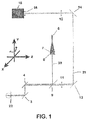
- FIG 1 shows schematically the optical components that constitute the instrument of the invention
- figures 2 and 3 show the instrument of the invention with all of its components mounted.
- the instrument comprises a frame 1 mounted on an ophthalmologic table 2, which can be oriented in three perpendicular directions X, Y, Z.
- Directions X, Z are on the same plane and direction Y is perpendicular to the plane of directions X, Z (see the axes system depicted in figure 2 ).
- the instrument has a support surface 19 for the head of the subject on whose eyes the measurements are going to be taken.
- the instrument also comprises an illumination sub-assembly 5 consisting of a fibre optic head 6; a lens 7 (L1), a diaphragm 8 (D), a beam splitter 9 (BS), and a measurement sub-assembly 10 with two lens 11 (L2) and 12 (L3), two mirrors 13 (M1) and 14 (M2), and a camera 15 with a matrix 16 of micro-lenses on the inlet of the camera 15, in such a way that said camera 15 is placed on the focal plane of the micro-lenses.
- Frame 1 has a motor 17 mounted on it (located on top of frame 1 in the embodiment of figures 2 and 3 ), the shaft of which rotates in the Y direction, to which an arm 18 is attached that can rotate on said shaft.
- the components of illumination sub-assembly 5, the components of measurement sub-assembly 10 and the camera 15 with the matrix 16 of micro-lenses are mounted on said arm 18.
- Input light 20 is depicted as a fine linear stroke and dark after fibre optic head 6, and output light 21 is depicted as a generally thicker linear stroke.
- Motor 17 employed can be a direct current servomotor. Likewise, the movement of motor 17 can be governed by a controller for direct current servomotor.
- the instrument can further comprise a laser pointer mounted on ophthalmologic table 2.
- the purpose of this element is to help the subject to stare at a point (in this case, the red point created by the laser pointer reflected on a surface located in front of the instrument).
- Arm 18 which is attached to the shaft of motor 17 and on which are mounted the components of illumination sub-assembly 5, the components of measurement sub-assembly 10 and the camera 15 with a matrix 16 of micro-lenses, can be L-shaped.
- the components of illumination sub-assembly 5 and the components of the measurement sub-assembly 10 are located on the vertical arm; the horizontal arm making it possible to distance said components to the desired measurement with respect to frame 1 of the instrument.
- support surface 19 for the head of the subject on whose eyes the measurements are going to be taken can consist in a chin rest with a curved concave central part, which makes it possible to restrain the head of the subject in a comfortable manner.
- the design of the instrument has been centred on measuring a single visual meridian, although it could also be used in all of the directions of the retina.
- the horizontal meridian was chosen because in the studies carried out to date, it has been found that this meridian is the most likely to be related to the possibility of developing myopia. It has yet to be determined up to what angle the peripheral vision could be important. For this reason the biggest angle possible up to which the Hartmann-Shack technique (on which it is based) can function without problems is being sought.
- the limit is around 35o to 40o of the visual angle. At greater than 40o, the size of the smallest radius of the elliptic pupil is too small in many subjects.
- the instrument has been designed for scanning on a field of 90o and measuring the central 80o of the field of vision.
- the speed of the measurement is important for the precision of the results.
- There are several dynamic sources in the eye accommodation, changes in the tear layer, and micro and macro saccadic movements) that can influence refraction and aberrations of the eye. To reduce the impact of these sources of error it is very important for the measurements to be taken rapidly (on the order of seconds).
- the duration of the measurements is also very important from the point of view of use of the instrument in clinical practice.
- An integral measurement (81 measurements on the horizontal meridian) takes 1.8 seconds. This makes it possible to measure the same eye several times in the same state. This allows taking an average which gives an even more precise result.
- An angular resolution of an image per angle is chosen.
- the high resolution also improves the precision of the results. It is a known fact that the variation of aberrations changes at a low frequency, and it is likewise known that when sudden changes are measured it is very likely due to a corrupted image, which can be eliminated without losing much information.
- Arm 18 L has two parts. An illumination part 5 and a measurement part. It is very important to ensure that the focal plane of L2 always coincides with PP 22 of the eye. It is mounted on a motor 17 which can rotate around the RY angle. Although it is not desirable to have moving components in the subject's field of vision, the design includes a large mirror 4 (LM) and a hot mirror 3 (HM). Both of these components are fixed. Given that hot mirror 3 is the only component placed in front of the eye of the subject, the subject has an open field of vision.
- Figure 1 displays a scheme of the system.
- a direct current servomotor governed by a controller can have speeds of 90o/s.
- a diode laser (whose light's wavelength is of 780 nm) connected to a fibre optic serves as a light source. The light enters the instrument at point F. D gives the possibility of adjusting the beam size between 1 mm for measuring and 12 mm for taking reference images.
- To reduce the size and weight of the system only one telescope (L2-L3) is used.
- ML is mounted on camera 15 using a type C mount. Camera 15 can have different technologies, sensor sizes and resolution times. In the case of the prototype developed to implement this invention, the camera has a 1024 x 768 pixel matrix with 8 bit resolution and can measure up to 117 images per second.
- Motor 17 functions with a USB cable and camera 15 through a standard Ethernet port, which makes it possible to use a standard computer.
- a specific support is designed to arrange all of the components of the instrument mounted on an ophthalmologic table 2 XYZ with chin rest. The table allows the instrument operator to align the instrument with the eye (right or left) of the subject without greatly bothering the subject by the side of the subject.
- Figures 2 and 3 show two views of the system.
- the only non-standard optical component is long mirror 4 (220 x 35 mm). This component is necessary because of the desire to avoid having moving components in the line of sight of the subject. For staring, the subject needs to look at a red point created by a laser point on the wall in front of the instrument.
- the laser is attached to table XYZ and always indicates the correct position to stare at from any position of the table.
- Aligning the instrument with the subject means putting the focal point of L2 in the centre of PP 22. Alignment follows a set and pre-established protocol. Two cameras are used. One shows the face / eyes of the subject. If the illuminating light does not enter the eye, the image of this camera can be seen, with a point on the face of the subject. Once the XY alignment is done, the system moves until reaching the position where the measuring beam enters the eye. Once the beam enters the eye, the HS camera begins registering images. The first alignment in direction Z is also done with the auxiliary camera. The system approaches until the cross drawn on the screen is superimposed on the pupil of the eye. To place the system in the correct position, arm 18 of the system moves up to 40o. When the HS image is in the same place as the image at 0°, the system is aligned. To ensure the measurements are always going to be correct, the system should also be placed at -40o. An experienced operator can align the instrument with the subject in about one minute.
- a program is developed for controlling the instrument.
- the movement of motor 17 and the saving of the images with the HS camera are synchronized by means of the software. Recording speed is calculated to optimize different parameters, such as illumination intensity, maximum speed of motor 17, maximum speed of camera 15, sensibility of camera 15, and synchronization software limits.
- the measurements are done continuously. This method has the drawback that the optical quality is not measured from a single point, but rather the result of an integration over a small path that is run. To reduce the error, the integration path is never more than 50% of the distance between two measurements. For this reason all of the measurements are isolated.
- the error is also very small because the density of the measurements is higher than the variability of the optical aberrations being investigated, which means that integration is carried out on a field having equal values.
- the method yields other advantages, as there is no loss of resolution. Integration reduces the important problem of coherent speckling that normally damages images taken at high velocity and results in higher quality images for analysis and processing. Furthermore, given that the instrument can move without stopping, there are no image perturbations caused by vibrations of motor 17.
- the standard system adjustments are detailed below:
- the system scans at a 90o angle.
- the images are only saved in the central zone of 80o so as to avoid perturbations of the images due to motor 17 stopping and starting.
- the illumination power is less than 10 ⁇ W, which is several orders of magnitude below the permitted exposure limits for this wavelength.
- Exposure time is 9 ms.
- the scanning is at 50o/s and the images are saved at 50 Hz. This means that an image is the integration of a path at a 0.45o visual angle and there is 0.55o of visible angle between the images.
- a measurement contains 81 HS images and saving it takes 1.8 seconds. Normally the measurement is repeated 4 times (324 HS images) and the result is the average.
- the total time is 7.2 seconds, which is still within the range in which the eye is at a constant state.
- the first phase consists in detecting the points in the HS image.
- the second phase consists in comparing the position of the points by measuring against the perfect position. The difference between both is used to determine the aberration of the wave expressed as a series of Zernike polynomials.
- the coefficients are rescaled to a circular pupil of 4 mm.
- the problem with elliptic pupils for measurements outside the axis is resolved by means of the enclosed circle method, as explained in the publication of L. Lundström, A. Mira-Agudela and P. Artal, "Peripheral optical errors and their change with accommodation differ between emmetropic and myopic eyes", Journal of Vision 9 (6), 1-11 (2009 ).
- the refraction is calculated based on the second order coefficients.
- the basic technique used in the instrument consists in an H-S sensor.
- the system is capable of measuring all of the aberrations and the refraction of the eye at an 80o angle within the field of vision with a resolution of 1 measurement per degree. In 1.8 seconds, 81 different angles can be measured.
- a new scanning method is used that makes rapid scanning possible over a wide angle of the retina. Given that from the mechanical point of view the method is optimized to take this type of measurements, it is possible to obtain a rapid, robust, precise and simple system.
Landscapes
- Life Sciences & Earth Sciences (AREA)
- Health & Medical Sciences (AREA)
- Medical Informatics (AREA)
- Biophysics (AREA)
- Ophthalmology & Optometry (AREA)
- Engineering & Computer Science (AREA)
- Biomedical Technology (AREA)
- Heart & Thoracic Surgery (AREA)
- Physics & Mathematics (AREA)
- Molecular Biology (AREA)
- Surgery (AREA)
- Animal Behavior & Ethology (AREA)
- General Health & Medical Sciences (AREA)
- Public Health (AREA)
- Veterinary Medicine (AREA)
- Eye Examination Apparatus (AREA)
Description
- The present invention refers to an instrument for measuring optical properties, refraction and aberrations of the eye in the entire field of vision, especially for application for prescriptions of new systems of correction, such as eye glasses or contact lenses, that can control myopia in children and adolescents.
- Nowadays, the interest in the quality of the peripheral vision of the human eye (that is, what occurs outside the central zone where details are seen clearly) is greater than ever. This interest began in the 70's with the suggestion that peripheral vision could be an important factor that influences the progression of myopia (see, for example, the publication of F. Rempt, J. Hoogerheide, and W.P.H. Hoogenboom, "Peripheral Retinoscopy and Skiagram", Ophthalmologica 162, 1-10 (1971), or the publication of J. Hoogerheide, F. Rempt, and W.P.H. Hoogenboom, "Acquired Myopia in Young Pilots", Ophthalmologica 163, 209-215 (1971)).
- To investigate said suggestion, several laboratories conducted tests with animals, as can observed in the following publications:
- F. Schaeffel, A. Glasser and H.C. Howland, "Accommodation, refractive error and eye growth in chickens", Vision Res. 28, 639-657 (1988).
- S. Diether and F. Schaeffel, "Local changes in Eye Growth induced by Imposed Local Refractive Error despite Active Accommodation", Vision Res. 37, 659-668 (1997).
- E.L. Smith, C. Kee, R. Ramamirham, Y. Qiao-Grider and L. Hung, "Peripheral Vision Can Influence Eye Growth and Refractive Development in Infant Monkeys", Invest. Ophthalmol. Vis. Sci. 46, 3965-3972 (2005).
- E.L. Smith, R. Ramamirtham, Y. Qiao-Grider, L. Hung, J. Huang, C. Kee, D. Coats and E. Paysse, "Effects of Foveal Ablation on Emmetropization and Form-Deprivation Myopia", Investigative Opthalmology & Visual Science 48, 3914-3922 (2007). D.O. Mutti, R.I. Sholtz, N.E. Friedman and K. Zadnik, "Peripheral Refraction and Ocular Shape in Children", Investigative Opthalmology & Visual Science 41, 1022-1030 (2000).
- The importance of peripheral vision in the progression of myopia has been reproduced in tests involving primates and other animals. With regard to experiments carried out on the human eye, several research groups have found correlations that may indicate that an eye that has relatively more hypermetropia in the peripheral retina than in the fovea has a greater likelihood of developing myopia, in accordance with the following publications:
- A. Seidemann, F. Schaeffel, A. Guirao, N. Lopez-Gil and P. Artal, "Peripheral refractive errors in myopic, emmetropic, and hyperopic young subjects", J. Opt. Soc. Am. A 19, 2363-2373 (2002).
- J. Wallman and J. Winawer, "Homeostasis of Eye Growth and the Question of Myopia", Neuron 43, 447-468 (2004).
- D.A. Atchison, N. Pritchard, K.L. Schmid, D.H. Scott, C.E. Jones and J.M. Pope, "Shape of the Retinal Surface in Emmetropia and Myopia", Investigative Opthalmology & Visual Science 46, 2698-2707 (2005).
- D.O. Mutti, J.R. Hayes, G.L. Mitchell, L.A. Jones, M.L. Moeschberger, S.A. Gotter, R.N. Kleinstein, R.E. Manny, J.D. Twelker and K. Zadnik, "Refrective Error, Axial Length, and Relative Peripheral Refractive Error before and after the Onset of Myopia", Investigative Opthalmology & Visual Science 48, 2510-2519 (2007).
- L. Lundström, A. Mira-Agudelo and P. Artal, "Peripheral optical errors and their change with accommodation differ between emmetropic and myopic eyes", Journal of Vision 9(6):17, 1-11 (2009).
- X. Chen, P. Sankaridurg, L. Donovan, Z. Lin, L. Li, A. Martinez, B. Holden and J. Ge, "Characteristics of peripheral refractive errors of myopic and non-myopic Chinese eyes", Vision Res. 50, 31-35 (2010).
- W.N. Charman, H. Radhakrishnan, "Peripheral refraction and the development of refractive error: a review", Ophtal. Physiol. Opt. 30, 321-338 (2010).
- Due to hypermetropia in the peripheral retina, the image is focused behind the retina. To obtain a focused image, the peripheral retina of the eye grows in order to compensate it, while at the same time it pushes the central retina back producing myopia. The first study with children who wear classes developed specifically for eliminating hypermetropia on the peripheral retina with the aim of preventing the progression of myopia corresponds to the publication by P.R. Sankaridurg, L. Donovan, S. Varnas, X. Chen, Z. Lin, S. Fisher, A. Ho, J. Ge, E. Smith and B. A. Holden, "Progression of Myopia With Spectacle Lenses Designed to Reduce Relative Peripheral Hyperopia: 12 Months Results", ARVO 2010 abstract, program # 2206.
-
ES-A1-2345027 - Currently, the most used technique for measuring ocular aberrations is based on the so called Hartmann-Shack wavefront sensor. Said method is employed in many research laboratories throughout the world, and is also the most frequently used in commercially available systems. It consists in a micro-lens matrix that is optically conjugated with the pupil of the eye, and a camera placed on the focal plane of the micro-lenses. If a flat wavefront reaches the sensor, the camera registers a perfectly regular point distribution, whereas if the wavefront is deformed (that is, it has aberrations) the point distribution will be irregular. Mathematically, the displacement of each point is directly proportional to the derivative of the wavefront from each micro-lens. Wave aberrations are calculated from the images of the points.
- To correctly investigate the impact of peripheral vision it is important to have instruments available that are capable of measuring it rapidly and with the necessary precision. Previously, instruments developed for measuring the refraction and / or aberrations of the central vision (on the fovea) were used. The only difference is that they require the subject to look at different angles in sequence while the fixed instrument takes the measurements. The measurements require a good deal of time (several minutes) and in order to shorten the time, the number of angles is reduced, which results in poor angular resolution. Furthermore, there are questions about whether rotating the eye changes the aberrations due to the tension of the eye muscles on the optics of the eye.
- There is a demand for instruments that explore all eye angles so as to improve the measurements. The main difference between a static system and a scanning system is that in the first the subject needs to change his line of sight, whereas in the second, it is the instrument that changes it position to measure other angles.
- There are two known instruments that perform a scan for measuring peripheral optical quality of the eye. The "peripheral photorefractor", in the document of J. Tabernero and F. Schaeffel, "Fast scanning photoretinoscope for measuring peripheral refraction as a function of accommodation", J. Opt. Soc. Am. A. 26, 2206-2210 (2009), is a system that only measures eye refraction on one meridian of the pupil. The instrument moves in a linear translation while rotating a beam splitter. It has a 90º scanning range. The advantages of the system are that it has a large scan field and that the alignment of the subject is less critical; however, it has several important drawbacks. The operating base of the method is empirical, and the calibration of the reflection of the light off the back of the eye is essential for obtaining correct results. Also, only the refraction from one meridian can be measured. That is, it provides very partial measurements of the peripheral optics of the eye. Moreover, due to its design, a mirror moves in front of the subject, a situation that could give rise to errors when used on subjects who lack experience, as they will tend to follow it during the measurement.
- The other scanner, disclosed in the document of X. Wei and L. Thibos, "Design and validation of a scanning Shack Hartmann aberrometer for measurements of the eye over a wide field of view", Optics express 18, 1134-1143 (2010), measures aberrations of the eyes with the Hartmann-Shack (HS) technique. As mentioned above, this technique measures the wavefront that leaves the eye (see the documents of J. Liang, B. Grimm, S. Goelz and J.F. Bille, "Objective measurement of wave aberrations of the human eye with the use of a Hartmann-Shack wave-front sensor", J. Opt. Soc. Am. A 7, 1949-1957 (1994); P. M. Prieto, F. Vargas-Martín, S. Goelz, P. Artal, "Analysis of the performance of the Hartmann-Shack sensor in the human eye", J. Opt. Soc. Am. A, 17, 1388-1398 (2000)). The advantages of the instrument are that the only moveable objects are two mirrors and that all of the aberrations are measured, as well as the refraction. The camp being measured is not only the nasal and temporal retina, but also the inferior and superior retina. The drawbacks are that the measurements have a very low density, as only a 30º field can be measured, which is too little to form a good idea of the peripheral vision. This system, which has already been published, covers a small field and is slow (it requires 8 seconds to measure 37 angles).
-
EP 1728467 A1 aims to enable to supply an optimal and dedicated spectacle lens or spectacle for each spectacle wearer, and also to verify a spectacle wearing state appropriately. A spectacle wearing parameter measurement system, sets a spectacle wearer to be in a distance vision state or a near vision state in which, in the near vision state, at least, one of an eyeball rotation angle and a near vision target distance is changeable optionally; takes an image of the spectacle wearer set in the distance vision state or near vision state by an image pickup device; imports the image; and measures and calculates a spectacle wearing parameter based on the image. A server computer of a factory received the image and uses the image data to manufacture a spectacle lens or a spectacle. Further, a spectacle wearing test system verifies whether or not a spectacle wearing state is appropriate based on a figure obtained by a comparison comparing a spectacle wearing parameter measured at present time after manufacturing the spectacle and the spectacle wearing parameter before manufacturing the spectacle. - Consequently, there is a need to have an instrument at hand to measure optical properties of the eye, refraction and aberrations, which is quick, robust, precise, and simple, and which makes it possible to take measurements on a broad visual field.
- The invention is defined in claim 1. Further aspects and preferred embodiments are defined in the appended claims. Aspects, embodiments and examples of the present disclosure which do not fall under the scope of the appended claims do not form part of the invention and are merely provided for illustrative purposes. Furthermore, the methods presented in the present description are provided for illustrative purposes only and do not form part of the present invention.
- The
object of the present invention is to provide an instrument for measuring the optical properties of the eye in the entire field of vision that resolves the mentioned drawbacks. - The present invention refers to a new instrument and a new manner of application of the technique, which can be applied to learn more about the contribution of peripheral vision to the progression of myopia, and also be used for personalizing prescriptions of new systems of eyeglasses for preventing myopia by controlling peripheral optics.
- The invention provides an instrument for measuring the optical properties of the eye in the entire field of vision, including refraction and aberrations, which comprises:
- a support surface for a head of a subject on whose eyes measurements are to be performed, with a plane of pupil of the eye;
- a frame mounted on an ophthalmologic table that can be oriented in three perpendicular directions X, Y, Z, with the X, Z directions being on the same plane and the Y direction perpendicular to the plane of the directions X, Z , a hot mirror and a long mirror being united to the frame and placed in front of the head of the subject;
- an optical assembly comprising an illumination sub-assembly consisting in a fibre optic head, a lens L1, a diaphragm D, a BS beam splitter, and a measurement sub-assembly with two lens L2 and L3, two mirrors M1 and M2 and a camera adapted with a matrix of micro-lenses on its inlet, in such a way that said camera is placed on the focal plane of the micro-lenses;
- wherein the frame has a motor mounted on it, the shaft of which rotates in the Y direction, to which an arm is attached that can rotate with said shaft and such that a conjugated plane of the micro-lenses coincides with the rotation axis of the shaft;
- wherein the optical assembly is mounted on the arm for rotational movement, the focal plane of the lens L2 coinciding with the plane of pupil of the eye.
- By means of this configuration with a rotating arm on which are mounted the illumination sub-assembly, the measurement sub-assembly and the camera with a matrix of micro-lenses the distance between the plane of the pupil of the eye of the subject on which the measurements are going to be taken and the components placed on said arm can be the same for all angles, the rotation axis being the same as the axis of the motor.
- Another advantage of the invention is that the subject whose eye is going to be measured remains still, without having to change his line of sight.
- Another advantage of the invention is that it enables the subject whose eye is going to be measured to remain stationary and comfortable, as it is possible to equip the instrument with a chin rest to support the chin.
- Other features and advantages of the present invention will be disclosed in the detailed description that follows from an exemplary embodiment of its object in relation to the accompanying figures.
- The following will illustrate, in a non-limiting manner, the object of the invention, making reference to the accompanying figures, in which:
-
Figure 1 shows a schematic view of the optical components of the instrument of the invention. -
Figure 2 shows a lateral view of the instrument of the invention with its components. -
Figure 3 shows a front view of the instrument of the invention with its components. -
Figure 1 shows schematically the optical components that constitute the instrument of the invention, andfigures 2 and3 show the instrument of the invention with all of its components mounted. - As can be seen in said figures, the instrument comprises a frame 1 mounted on an ophthalmologic table 2, which can be oriented in three perpendicular directions X, Y, Z. Directions X, Z are on the same plane and direction Y is perpendicular to the plane of directions X, Z (see the axes system depicted in
figure 2 ). The instrument has asupport surface 19 for the head of the subject on whose eyes the measurements are going to be taken. Located in front of the head of the subject and united to frame 1 there is ahot mirror 3 and a long mirror 4. - The instrument also comprises an
illumination sub-assembly 5 consisting of a fibre optic head 6; a lens 7 (L1), a diaphragm 8 (D), a beam splitter 9 (BS), and ameasurement sub-assembly 10 with two lens 11 (L2) and 12 (L3), two mirrors 13 (M1) and 14 (M2), and acamera 15 with amatrix 16 of micro-lenses on the inlet of thecamera 15, in such a way that saidcamera 15 is placed on the focal plane of the micro-lenses. Frame 1 has amotor 17 mounted on it (located on top of frame 1 in the embodiment offigures 2 and3 ), the shaft of which rotates in the Y direction, to which anarm 18 is attached that can rotate on said shaft. The components ofillumination sub-assembly 5, the components ofmeasurement sub-assembly 10 and thecamera 15 with thematrix 16 of micro-lenses are mounted on saidarm 18. -
Input light 20 is depicted as a fine linear stroke and dark after fibre optic head 6, andoutput light 21 is depicted as a generally thicker linear stroke. -
Motor 17 employed can be a direct current servomotor. Likewise, the movement ofmotor 17 can be governed by a controller for direct current servomotor. - The instrument can further comprise a laser pointer mounted on ophthalmologic table 2. The purpose of this element is to help the subject to stare at a point (in this case, the red point created by the laser pointer reflected on a surface located in front of the instrument).
-
Arm 18 which is attached to the shaft ofmotor 17 and on which are mounted the components ofillumination sub-assembly 5, the components ofmeasurement sub-assembly 10 and thecamera 15 with amatrix 16 of micro-lenses, can be L-shaped. Infigure 2 it can be seen that the components ofillumination sub-assembly 5 and the components of themeasurement sub-assembly 10 are located on the vertical arm; the horizontal arm making it possible to distance said components to the desired measurement with respect to frame 1 of the instrument. - Likewise,
support surface 19 for the head of the subject on whose eyes the measurements are going to be taken, can consist in a chin rest with a curved concave central part, which makes it possible to restrain the head of the subject in a comfortable manner. - The design of the instrument has been centred on measuring a single visual meridian, although it could also be used in all of the directions of the retina. The horizontal meridian was chosen because in the studies carried out to date, it has been found that this meridian is the most likely to be related to the possibility of developing myopia. It has yet to be determined up to what angle the peripheral vision could be important. For this reason the biggest angle possible up to which the Hartmann-Shack technique (on which it is based) can function without problems is being sought. The limit is around 35º to 40º of the visual angle. At greater than 40º, the size of the smallest radius of the elliptic pupil is too small in many subjects. The instrument has been designed for scanning on a field of 90º and measuring the central 80º of the field of vision. The speed of the measurement is important for the precision of the results. There are several dynamic sources in the eye (accommodation, changes in the tear layer, and micro and macro saccadic movements) that can influence refraction and aberrations of the eye. To reduce the impact of these sources of error it is very important for the measurements to be taken rapidly (on the order of seconds). The duration of the measurements is also very important from the point of view of use of the instrument in clinical practice. An integral measurement (81 measurements on the horizontal meridian) takes 1.8 seconds. This makes it possible to measure the same eye several times in the same state. This allows taking an average which gives an even more precise result.
- An angular resolution of an image per angle is chosen. The high resolution also improves the precision of the results. It is a known fact that the variation of aberrations changes at a low frequency, and it is likewise known that when sudden changes are measured it is very likely due to a corrupted image, which can be eliminated without losing much information.
- The main difference between static measurements and scanned measurements has been explained above. When the subject does not need to change the direction of the eyesight between different measurements, measurement time can be reduced and the eye maintains the same muscle tension during all of the measurements. Given that the subject's comfort is very important for obtaining good measurements, our design uses a chin rest to hold the head and there are no components that move through the line on which the subject is staring.
- For precise measuring it is important that the distance between the plane of
pupil 22 of the eye (PP) and the HS sensor remains the same at all angles. For this reason, our instrument is based on a rotational movement so that each point of the circle is exactly the same distance from the centre. The point of rotation is the centre ofmotor 17. This point is translated toPP 22 of the eye with an L-shapedarm 18, which holds different optical components. Calculating the dimensions of the system is necessary to optimise different parameters. The radius of rotation is a function of the desired dimensions, angular scan range, reduction of the telescopic optic, system weight and use of standard optical and mechanical components. - Arm 18 L has two parts. An
illumination part 5 and a measurement part. It is very important to ensure that the focal plane of L2 always coincides withPP 22 of the eye. It is mounted on amotor 17 which can rotate around the RY angle. Although it is not desirable to have moving components in the subject's field of vision, the design includes a large mirror 4 (LM) and a hot mirror 3 (HM). Both of these components are fixed. Given thathot mirror 3 is the only component placed in front of the eye of the subject, the subject has an open field of vision.Figure 1 displays a scheme of the system. - A direct current servomotor governed by a controller can have speeds of 90º/s. A diode laser (whose light's wavelength is of 780 nm) connected to a fibre optic serves as a light source. The light enters the instrument at point F. D gives the possibility of adjusting the beam size between 1 mm for measuring and 12 mm for taking reference images. To reduce the size and weight of the system only one telescope (L2-L3) is used. ML is mounted on
camera 15 using a type C mount.Camera 15 can have different technologies, sensor sizes and resolution times. In the case of the prototype developed to implement this invention, the camera has a 1024 x 768 pixel matrix with 8 bit resolution and can measure up to 117 images per second.Motor 17 functions with a USB cable andcamera 15 through a standard Ethernet port, which makes it possible to use a standard computer. A specific support is designed to arrange all of the components of the instrument mounted on an ophthalmologic table 2 XYZ with chin rest. The table allows the instrument operator to align the instrument with the eye (right or left) of the subject without greatly bothering the subject by the side of the subject.Figures 2 and3 show two views of the system. - The only non-standard optical component is long mirror 4 (220 x 35 mm). This component is necessary because of the desire to avoid having moving components in the line of sight of the subject. For staring, the subject needs to look at a red point created by a laser point on the wall in front of the instrument. The laser is attached to table XYZ and always indicates the correct position to stare at from any position of the table.
- Aligning the instrument with the subject means putting the focal point of L2 in the centre of
PP 22. Alignment follows a set and pre-established protocol. Two cameras are used. One shows the face / eyes of the subject. If the illuminating light does not enter the eye, the image of this camera can be seen, with a point on the face of the subject. Once the XY alignment is done, the system moves until reaching the position where the measuring beam enters the eye. Once the beam enters the eye, the HS camera begins registering images. The first alignment in direction Z is also done with the auxiliary camera. The system approaches until the cross drawn on the screen is superimposed on the pupil of the eye. To place the system in the correct position,arm 18 of the system moves up to 40º. When the HS image is in the same place as the image at 0°, the system is aligned. To ensure the measurements are always going to be correct, the system should also be placed at -40º. An experienced operator can align the instrument with the subject in about one minute. - Saving the images is completely automatic. A program is developed for controlling the instrument. The movement of
motor 17 and the saving of the images with the HS camera are synchronized by means of the software. Recording speed is calculated to optimize different parameters, such as illumination intensity, maximum speed ofmotor 17, maximum speed ofcamera 15, sensibility ofcamera 15, and synchronization software limits. To reduce image saving time the measurements are done continuously. This method has the drawback that the optical quality is not measured from a single point, but rather the result of an integration over a small path that is run. To reduce the error, the integration path is never more than 50% of the distance between two measurements. For this reason all of the measurements are isolated. The error is also very small because the density of the measurements is higher than the variability of the optical aberrations being investigated, which means that integration is carried out on a field having equal values. The method yields other advantages, as there is no loss of resolution. Integration reduces the important problem of coherent speckling that normally damages images taken at high velocity and results in higher quality images for analysis and processing. Furthermore, given that the instrument can move without stopping, there are no image perturbations caused by vibrations ofmotor 17. - The standard system adjustments are detailed below: The system scans at a 90º angle. The images are only saved in the central zone of 80º so as to avoid perturbations of the images due to
motor 17 stopping and starting. The illumination power is less than 10 µW, which is several orders of magnitude below the permitted exposure limits for this wavelength. Exposure time is 9 ms. The scanning is at 50º/s and the images are saved at 50 Hz. This means that an image is the integration of a path at a 0.45º visual angle and there is 0.55º of visible angle between the images. A measurement contains 81 HS images and saving it takes 1.8 seconds. Normally the measurement is repeated 4 times (324 HS images) and the result is the average. The total time is 7.2 seconds, which is still within the range in which the eye is at a constant state. - To determine optical aberrations based on HS images, a program was developed that combines different algorithms created to make the different phases of the elaboration. The first phase consists in detecting the points in the HS image. The second phase consists in comparing the position of the points by measuring against the perfect position. The difference between both is used to determine the aberration of the wave expressed as a series of Zernike polynomials. In the last phase the coefficients are rescaled to a circular pupil of 4 mm. The problem with elliptic pupils for measurements outside the axis is resolved by means of the enclosed circle method, as explained in the publication of L. Lundström, A. Mira-Agudela and P. Artal, "Peripheral optical errors and their change with accommodation differ between emmetropic and myopic eyes", Journal of Vision 9 (6), 1-11 (2009). The refraction is calculated based on the second order coefficients.
- As has been seen, the basic technique used in the instrument consists in an H-S sensor. The system is capable of measuring all of the aberrations and the refraction of the eye at an 80º angle within the field of vision with a resolution of 1 measurement per degree. In 1.8 seconds, 81 different angles can be measured. A new scanning method is used that makes rapid scanning possible over a wide angle of the retina. Given that from the mechanical point of view the method is optimized to take this type of measurements, it is possible to obtain a rapid, robust, precise and simple system.
- With the instrument of the invention a rapid system for measuring the optical quality on the retinal periphery of the eye is achieved. Without movements of the subject, rapid and precise. The refraction and optical results can be used for prescribing eyeglasses to control myopia.
- The same scanning principle could be applied to other systems of measurement of the optics of the eye besides Hartmann-Shack, as is proposed herein.
- Although some embodiments of the invention have been described and depicted, it is obvious that modifications can be made to them within their scope, and that the invention should not be considered limited to said embodiments, but rather only to the content of the following claims.
Claims (8)
- An instrument for measuring the optical properties of the eye in the entire field of vision, including refraction and aberrations, which comprises:a support surface (19) for a head of a subject on whose eyes measurements are to be performed, with a plane of pupil (22) of the eye;a frame (1) mounted on an ophthalmologic table (2) that can be oriented in three perpendicular directions X, Y, Z, with the X, Z directions being on the same plane and the Y direction perpendicular to the plane of the directions X, Z , a hot mirror (3) and a long mirror (4) being united to the frame (1) and placed in front of the head of the subject;an optical assembly comprising an illumination sub-assembly (5) consisting in a fibre optic head (6), a lens (7) L1, a diaphragm (8) D, a BS beam splitter (9), and a measurement sub-assembly (10) with two lens L2 (11) and L3 (12), two mirrors M1 (13) and M2 (14) and a camera (15) adapted with a matrix (16) of micro-lenses on its inlet, in such a way that said camera (15) is placed on the focal plane of the micro-lenses;characterized in that the frame (1) has a motor (17) mounted on it, the shaft of which rotates in the Y direction, to which an arm (18) is attached that can rotate with said shaft and such that a conjugated plane of the micro-lenses coindices with the rotation axis of the shaft;wherein the optical assembly is mounted on the arm (18) for rotational movement, the focal plane of the lens L2 (11) coinciding with the plane of pupil (22) of the eye.
- Instrument for measuring the optical properties of the eye in the entire field of vision, in accordance with claim 1, characterized in that motor (17) is a direct current servomotor.
- Instrument for measuring the optical properties of the eye in the entire field of vision, in accordance with claim 2, characterized in that the movement of motor (17) is governed by a direct current servomotor controller.
- Instrument for measuring the optical properties of the eye in the entire field of vision, in accordance with any of the previous claims, characterized in that it further comprises a laser pointer mounted on the ophthalmologic table (2).
- Instrument for measuring the optical properties of the eye in the entire field of vision in accordance with any of the previous claims, characterized in that the arm (18) that attaches to the shaft of the motor (17), on which are mounted the components of the illumination sub-assembly (5) and the measurement sub-assembly (10), is L-shaped.
- Instrument for measuring the optical properties of the eye in the entire field of vision, in accordance with any of the previous claims, characterized in that the support surface (19) for the head of the subject on whose eyes the measurements are going to be taken consists in a chin rest with a curved concave central part.
- Instrument for measuring the optical properties of the eye in the entire field of vision, in accordance with any of the previous claims, characterized in that the motor (17) and the camera (15) are connected to a computer.
- Instrument for measuring the optical properties of the eye in the entire field of vision, in accordance with claim 1, wherein the hot mirror (3) is the only component placed in front of the eye of the subject, the subject thus having an open field of vision.
Applications Claiming Priority (2)
| Application Number | Priority Date | Filing Date | Title |
|---|---|---|---|
| ES201031526A ES2380469B2 (en) | 2010-10-15 | 2010-10-15 | INSTRUMENT FOR THE QUICK MEASURE OF THE OPTICAL PROPERTIES OF THE EYE IN THE VISUAL FIELD. |
| PCT/ES2011/070640 WO2012049343A1 (en) | 2010-10-15 | 2011-09-13 | Instrument for rapid measurement of the optical properties of the eye across the whole field of vision. |
Publications (3)
| Publication Number | Publication Date |
|---|---|
| EP2628441A1 EP2628441A1 (en) | 2013-08-21 |
| EP2628441A4 EP2628441A4 (en) | 2016-12-28 |
| EP2628441B1 true EP2628441B1 (en) | 2019-01-16 |
Family
ID=45937933
Family Applications (1)
| Application Number | Title | Priority Date | Filing Date |
|---|---|---|---|
| EP11832172.8A Active EP2628441B1 (en) | 2010-10-15 | 2011-09-13 | Instrument for rapid measurement of the optical properties of the eye across the whole field of vision |
Country Status (5)
| Country | Link |
|---|---|
| US (1) | US9167965B2 (en) |
| EP (1) | EP2628441B1 (en) |
| CN (1) | CN103153170B (en) |
| ES (2) | ES2380469B2 (en) |
| WO (1) | WO2012049343A1 (en) |
Families Citing this family (12)
| Publication number | Priority date | Publication date | Assignee | Title |
|---|---|---|---|---|
| KR101525352B1 (en) * | 2014-04-25 | 2015-06-03 | 한정우 | Retinoscope |
| CN104905763B (en) | 2015-06-18 | 2017-12-19 | 苏州四海通仪器有限公司 | The optometry equipment of measurable other center defocus |
| ES2734740A1 (en) * | 2018-06-08 | 2019-12-11 | Bart Jan Jaeken | VIRTUAL REALITY INSTRUMENT TO MEASURE THE REFRACTION AND ABERRATIONS OF THE AUTOMATIC EYE (Machine-translation by Google Translate, not legally binding) |
| CN109512380A (en) * | 2018-11-02 | 2019-03-26 | 爱尔眼科医院集团股份有限公司 | The method for making full retina dioptric topographic map based on wavefront sensing technique |
| US12329514B2 (en) | 2020-01-09 | 2025-06-17 | Wavefront Dynamics, Inc. | Methods for dynamic position measurement of ocular structures using purkinje reflection spots |
| US12343081B2 (en) | 2021-05-19 | 2025-07-01 | Wavefront Dynamics, Inc. | Optical aberrometer systems for customizing intraocular lens |
| US12458536B2 (en) | 2021-05-19 | 2025-11-04 | Wavefront Dynamics, Inc. | Methods for customizing intraocular lens using an optical aberrometer |
| CN113616152A (en) | 2021-07-29 | 2021-11-09 | 爱尔眼科医院集团股份有限公司 | Ophthalmological instrument for measuring the optical quality of an eye |
| CN114246546A (en) * | 2022-01-25 | 2022-03-29 | 南京博视医疗科技有限公司 | Whole eyeball biological measurement system and measurement method thereof |
| CN115956875A (en) * | 2022-11-23 | 2023-04-14 | 杭州微晓医疗科技有限公司 | System and method for optical inspection of eye |
| WO2025008995A1 (en) * | 2023-07-06 | 2025-01-09 | Elisar Life Sciences Private Limited | System for alignment of ophthalmic diagnostic devices |
| WO2026044586A1 (en) | 2024-08-29 | 2026-03-05 | Carl Zeiss Vision International Gmbh | Ophthalmic lens and method for customizing defocus in myopia control |
Family Cites Families (37)
| Publication number | Priority date | Publication date | Assignee | Title |
|---|---|---|---|---|
| DE1253794B (en) * | 1965-11-25 | 1967-11-09 | Zeiss Carl Fa | Device for remote adjustment of measuring or work tables |
| US4490022A (en) * | 1982-01-04 | 1984-12-25 | Reynolds Alvin E | Apparatus for corneal corrective techniques |
| JPS5938A (en) * | 1982-06-23 | 1984-01-05 | 有限会社 宇津木光学研究所 | Intraocular observing and inspecting apparatus |
| NO151294C (en) | 1982-12-22 | 1985-03-13 | Norsk Hydro As | PREPARATION OF ENZYMETE BETA-GLUCANASE FOR THE PREPARATION OF SOPHES |
| JPS6060831A (en) * | 1983-09-14 | 1985-04-08 | 株式会社トプコン | fundus camera |
| US5227818A (en) * | 1987-08-26 | 1993-07-13 | El Hage Sami G | Apparatus for determining the contour of the cornea of a human eye |
| US5090797A (en) * | 1989-06-09 | 1992-02-25 | Lc Technologies Inc. | Method and apparatus for mirror control |
| US5120122A (en) * | 1990-03-08 | 1992-06-09 | Nishika Limited | Simultaneous stereo fundus camera |
| US5291231A (en) * | 1990-11-29 | 1994-03-01 | Kabushiki Kaisha Topcon | Opthalmological image processing system |
| US5220361A (en) * | 1991-06-05 | 1993-06-15 | Allergan Humphrey | Gaze tracking for field analyzer |
| US6450641B2 (en) * | 1992-06-02 | 2002-09-17 | Lasersight Technologies, Inc. | Method of corneal analysis using a checkered placido apparatus |
| US5491757A (en) * | 1993-12-22 | 1996-02-13 | Humphrey Instruments, Inc. | Field tester gaze tracking using content addressable memories to improve image data analysis speed |
| US5459536A (en) * | 1993-12-27 | 1995-10-17 | Alcon Laboratories, Inc. | Apparatus and method for automated perimetry |
| IL132123A0 (en) * | 1997-04-01 | 2001-03-19 | Univ Johns Hopkins | A system for imaging an ocular fundus semi-automatically at high resolution and wide field |
| DE59801938D1 (en) * | 1997-11-11 | 2001-12-06 | Haag Streit Ag Koeniz | Device for stereoscopic examination of a patient's eye |
| US5926252A (en) * | 1998-08-25 | 1999-07-20 | Reyburn; Thomas P. | Ophthalmic instrument that measures rotation of a toric contact lens |
| US7303281B2 (en) * | 1998-10-07 | 2007-12-04 | Tracey Technologies, Llc | Method and device for determining refractive components and visual function of the eye for vision correction |
| UA46833C2 (en) * | 1998-10-07 | 2002-06-17 | Інститут Біомедичної Техніки Та Технологій Академії Технологічних Наук України | EYE ABERATIONAL REFRACTION MEASURING INSTRUMENT |
| US6460997B1 (en) * | 2000-05-08 | 2002-10-08 | Alcon Universal Ltd. | Apparatus and method for objective measurements of optical systems using wavefront analysis |
| US6361167B1 (en) * | 2000-06-13 | 2002-03-26 | Massie Research Laboratories, Inc. | Digital eye camera |
| US6685317B2 (en) * | 2000-06-13 | 2004-02-03 | Massie Research Laboratories, Inc. | Digital eye camera |
| US6631990B2 (en) * | 2001-01-03 | 2003-10-14 | Acmed, Inc. | System for measuring distances in the anterior chamber of the eye |
| US6575572B2 (en) * | 2001-09-21 | 2003-06-10 | Carl Zeiss Ophthalmic Systems, Inc. | Method and apparatus for measuring optical aberrations of an eye |
| JP2003126043A (en) * | 2001-10-22 | 2003-05-07 | Canon Inc | Ophthalmic imaging equipment |
| JP4162450B2 (en) * | 2002-08-29 | 2008-10-08 | 株式会社ニデック | Cornea surgery device |
| CN101692979B (en) * | 2003-04-11 | 2011-08-31 | 博士伦公司 | System and method for acquiring data and aligning and tracking of eye |
| JP4428987B2 (en) * | 2003-11-17 | 2010-03-10 | キヤノン株式会社 | Ophthalmic equipment |
| EP1728467A4 (en) * | 2004-03-26 | 2009-09-16 | Hoya Corp | Spectacle lens supply system, spectacle wearing parameter measurement device, spectacle wearing inspection system, spectacle lens, and spectacle |
| US7527380B2 (en) * | 2006-02-09 | 2009-05-05 | Sis Ag, Surgical Instrument Systems | Ophthalmological measuring device |
| CN101051347B (en) * | 2006-04-07 | 2011-04-20 | 北京凯平艾森信息技术有限公司 | Eye image collector |
| JP4776450B2 (en) * | 2006-06-16 | 2011-09-21 | 株式会社トプコン | Ophthalmic imaging equipment |
| US7575322B2 (en) * | 2007-05-11 | 2009-08-18 | Amo Development Llc. | Auto-alignment and auto-focus system and method |
| US8348429B2 (en) * | 2008-03-27 | 2013-01-08 | Doheny Eye Institute | Optical coherence tomography device, method, and system |
| JP5248926B2 (en) * | 2008-06-05 | 2013-07-31 | 株式会社ニデック | Eye refractive power measuring device |
| ES2346392B1 (en) * | 2009-03-04 | 2011-10-03 | Voptica, S.L. | METHOD OF MEASUREMENT AND BINOCULAR CONTROL OF EYE ABERRATIONS, SIMULTANEOUS PRESENTATION OF VISUAL STIMULES, AND OPHTHALMIC INSTRUMENT THAT IMPLEMENTS SUCH METHOD. |
| ES2345027B1 (en) * | 2009-03-12 | 2011-09-30 | Universidad De Murcia | OPTICAL REFRACTION CORRECTION DEVICE IN THE PERIPHERAL RETINA OF ASYMMETRICAL WAY FOR THE CONTROL OF THE PROGRESSION OF MYOPIA. |
| GB0907557D0 (en) | 2009-05-01 | 2009-06-10 | Optos Plc | Improvements in or relating to scanning ophthalmoscopes |
-
2010
- 2010-10-15 ES ES201031526A patent/ES2380469B2/en active Active
-
2011
- 2011-09-13 CN CN201180049551.1A patent/CN103153170B/en active Active
- 2011-09-13 WO PCT/ES2011/070640 patent/WO2012049343A1/en not_active Ceased
- 2011-09-13 EP EP11832172.8A patent/EP2628441B1/en active Active
- 2011-09-13 ES ES11832172T patent/ES2718501T3/en active Active
- 2011-09-13 US US13/823,121 patent/US9167965B2/en active Active
Non-Patent Citations (1)
| Title |
|---|
| None * |
Also Published As
| Publication number | Publication date |
|---|---|
| ES2380469B2 (en) | 2013-04-10 |
| US9167965B2 (en) | 2015-10-27 |
| ES2380469A1 (en) | 2012-05-14 |
| CN103153170B (en) | 2016-06-29 |
| CN103153170A (en) | 2013-06-12 |
| EP2628441A1 (en) | 2013-08-21 |
| WO2012049343A1 (en) | 2012-04-19 |
| EP2628441A4 (en) | 2016-12-28 |
| US20130265544A1 (en) | 2013-10-10 |
| ES2718501T3 (en) | 2019-07-02 |
Similar Documents
| Publication | Publication Date | Title |
|---|---|---|
| US9167965B2 (en) | Instrument for rapid measurement of the optical properties of the eye in the entire field of vision | |
| EP2991540B1 (en) | Method and system for determining the refractive properties of an eye of a child | |
| Tabernero et al. | More irregular eye shape in low myopia than in emmetropia | |
| CN110367924B (en) | Subjective and objective integrated precise optometry device and optometry method | |
| KR20140108657A (en) | Device and method for determining at least one objective eye refraction parameter of a subject depending on a plurality of gaze directions | |
| US12285214B2 (en) | Wide-field multi-axis aberrometer | |
| KR20140134648A (en) | A refractometer with a remote wavefront generator | |
| CN109512380A (en) | The method for making full retina dioptric topographic map based on wavefront sensing technique | |
| US20200081269A1 (en) | Apparatus, Method and System for Measuring the Influence of Ophthalmic Lens Design | |
| López-Gil et al. | Limitations of the ocular wavefront correction with contact lenses | |
| CN114209559B (en) | Image display method, device and system | |
| US7559652B2 (en) | Adaptive optic ophthalmic design system | |
| Zhao et al. | Validation of widefield aberrometer for global peripheral aberration scanning | |
| WO2024229246A1 (en) | Scanning ocular wavefront sensor for characterizing optical quality across retinal eccentricity | |
| JP7021540B2 (en) | Awareness-based optometry device | |
| HK1261005B (en) | Method and system for determining the refractive properties of an eye of a child | |
| CN118234424A (en) | Method for comparing two ophthalmic lenses with different optical designs | |
| Osuagwu | Limitations in peripheral optics measurement of the eye | |
| Xu et al. | Information fusion method for ocular aberrations measurement based on subjective visual compensation | |
| Dubinin et al. | Methods of isoplanatic patch widening in human eye retina imaging | |
| Dubinin et al. | Adaptive optics in ophthalmology: current techniques and new methods of increasing field-of-view of fundus cameras | |
| HK1221628B (en) | Method and system for determining the refractive properties of an eye of a child | |
| Sahin | Correction of the aberrations of the eye using adaptive optics with pupil tracking |
Legal Events
| Date | Code | Title | Description |
|---|---|---|---|
| PUAI | Public reference made under article 153(3) epc to a published international application that has entered the european phase |
Free format text: ORIGINAL CODE: 0009012 |
|
| 17P | Request for examination filed |
Effective date: 20130429 |
|
| AK | Designated contracting states |
Kind code of ref document: A1 Designated state(s): AL AT BE BG CH CY CZ DE DK EE ES FI FR GB GR HR HU IE IS IT LI LT LU LV MC MK MT NL NO PL PT RO RS SE SI SK SM TR |
|
| DAX | Request for extension of the european patent (deleted) | ||
| RIC1 | Information provided on ipc code assigned before grant |
Ipc: A61B 3/103 20060101AFI20161115BHEP |
|
| RA4 | Supplementary search report drawn up and despatched (corrected) |
Effective date: 20161125 |
|
| RIC1 | Information provided on ipc code assigned before grant |
Ipc: A61B 3/103 20060101AFI20161118BHEP |
|
| GRAP | Despatch of communication of intention to grant a patent |
Free format text: ORIGINAL CODE: EPIDOSNIGR1 |
|
| STAA | Information on the status of an ep patent application or granted ep patent |
Free format text: STATUS: GRANT OF PATENT IS INTENDED |
|
| RIC1 | Information provided on ipc code assigned before grant |
Ipc: A61B 3/10 20060101ALI20180718BHEP Ipc: A61B 3/00 20060101ALI20180718BHEP Ipc: A61B 3/103 20060101AFI20180718BHEP |
|
| INTG | Intention to grant announced |
Effective date: 20180810 |
|
| RIN1 | Information on inventor provided before grant (corrected) |
Inventor name: JAEKEN, BART Inventor name: ARTAL SORIANO, PABLO |
|
| GRAS | Grant fee paid |
Free format text: ORIGINAL CODE: EPIDOSNIGR3 |
|
| GRAA | (expected) grant |
Free format text: ORIGINAL CODE: 0009210 |
|
| STAA | Information on the status of an ep patent application or granted ep patent |
Free format text: STATUS: THE PATENT HAS BEEN GRANTED |
|
| AK | Designated contracting states |
Kind code of ref document: B1 Designated state(s): AL AT BE BG CH CY CZ DE DK EE ES FI FR GB GR HR HU IE IS IT LI LT LU LV MC MK MT NL NO PL PT RO RS SE SI SK SM TR |
|
| REG | Reference to a national code |
Ref country code: GB Ref legal event code: FG4D |
|
| REG | Reference to a national code |
Ref country code: CH Ref legal event code: EP |
|
| REG | Reference to a national code |
Ref country code: IE Ref legal event code: FG4D |
|
| REG | Reference to a national code |
Ref country code: DE Ref legal event code: R096 Ref document number: 602011055806 Country of ref document: DE |
|
| REG | Reference to a national code |
Ref country code: AT Ref legal event code: REF Ref document number: 1089051 Country of ref document: AT Kind code of ref document: T Effective date: 20190215 |
|
| REG | Reference to a national code |
Ref country code: NL Ref legal event code: MP Effective date: 20190116 |
|
| REG | Reference to a national code |
Ref country code: LT Ref legal event code: MG4D |
|
| PG25 | Lapsed in a contracting state [announced via postgrant information from national office to epo] |
Ref country code: NL Free format text: LAPSE BECAUSE OF FAILURE TO SUBMIT A TRANSLATION OF THE DESCRIPTION OR TO PAY THE FEE WITHIN THE PRESCRIBED TIME-LIMIT Effective date: 20190116 |
|
| REG | Reference to a national code |
Ref country code: ES Ref legal event code: FG2A Ref document number: 2718501 Country of ref document: ES Kind code of ref document: T3 Effective date: 20190702 |
|
| REG | Reference to a national code |
Ref country code: AT Ref legal event code: MK05 Ref document number: 1089051 Country of ref document: AT Kind code of ref document: T Effective date: 20190116 |
|
| PG25 | Lapsed in a contracting state [announced via postgrant information from national office to epo] |
Ref country code: PL Free format text: LAPSE BECAUSE OF FAILURE TO SUBMIT A TRANSLATION OF THE DESCRIPTION OR TO PAY THE FEE WITHIN THE PRESCRIBED TIME-LIMIT Effective date: 20190116 Ref country code: LT Free format text: LAPSE BECAUSE OF FAILURE TO SUBMIT A TRANSLATION OF THE DESCRIPTION OR TO PAY THE FEE WITHIN THE PRESCRIBED TIME-LIMIT Effective date: 20190116 Ref country code: FI Free format text: LAPSE BECAUSE OF FAILURE TO SUBMIT A TRANSLATION OF THE DESCRIPTION OR TO PAY THE FEE WITHIN THE PRESCRIBED TIME-LIMIT Effective date: 20190116 Ref country code: PT Free format text: LAPSE BECAUSE OF FAILURE TO SUBMIT A TRANSLATION OF THE DESCRIPTION OR TO PAY THE FEE WITHIN THE PRESCRIBED TIME-LIMIT Effective date: 20190516 Ref country code: NO Free format text: LAPSE BECAUSE OF FAILURE TO SUBMIT A TRANSLATION OF THE DESCRIPTION OR TO PAY THE FEE WITHIN THE PRESCRIBED TIME-LIMIT Effective date: 20190416 Ref country code: SE Free format text: LAPSE BECAUSE OF FAILURE TO SUBMIT A TRANSLATION OF THE DESCRIPTION OR TO PAY THE FEE WITHIN THE PRESCRIBED TIME-LIMIT Effective date: 20190116 |
|
| PG25 | Lapsed in a contracting state [announced via postgrant information from national office to epo] |
Ref country code: LV Free format text: LAPSE BECAUSE OF FAILURE TO SUBMIT A TRANSLATION OF THE DESCRIPTION OR TO PAY THE FEE WITHIN THE PRESCRIBED TIME-LIMIT Effective date: 20190116 Ref country code: BG Free format text: LAPSE BECAUSE OF FAILURE TO SUBMIT A TRANSLATION OF THE DESCRIPTION OR TO PAY THE FEE WITHIN THE PRESCRIBED TIME-LIMIT Effective date: 20190416 Ref country code: IS Free format text: LAPSE BECAUSE OF FAILURE TO SUBMIT A TRANSLATION OF THE DESCRIPTION OR TO PAY THE FEE WITHIN THE PRESCRIBED TIME-LIMIT Effective date: 20190516 Ref country code: RS Free format text: LAPSE BECAUSE OF FAILURE TO SUBMIT A TRANSLATION OF THE DESCRIPTION OR TO PAY THE FEE WITHIN THE PRESCRIBED TIME-LIMIT Effective date: 20190116 Ref country code: GR Free format text: LAPSE BECAUSE OF FAILURE TO SUBMIT A TRANSLATION OF THE DESCRIPTION OR TO PAY THE FEE WITHIN THE PRESCRIBED TIME-LIMIT Effective date: 20190417 Ref country code: HR Free format text: LAPSE BECAUSE OF FAILURE TO SUBMIT A TRANSLATION OF THE DESCRIPTION OR TO PAY THE FEE WITHIN THE PRESCRIBED TIME-LIMIT Effective date: 20190116 |
|
| REG | Reference to a national code |
Ref country code: DE Ref legal event code: R097 Ref document number: 602011055806 Country of ref document: DE |
|
| PG25 | Lapsed in a contracting state [announced via postgrant information from national office to epo] |
Ref country code: AL Free format text: LAPSE BECAUSE OF FAILURE TO SUBMIT A TRANSLATION OF THE DESCRIPTION OR TO PAY THE FEE WITHIN THE PRESCRIBED TIME-LIMIT Effective date: 20190116 Ref country code: SK Free format text: LAPSE BECAUSE OF FAILURE TO SUBMIT A TRANSLATION OF THE DESCRIPTION OR TO PAY THE FEE WITHIN THE PRESCRIBED TIME-LIMIT Effective date: 20190116 Ref country code: RO Free format text: LAPSE BECAUSE OF FAILURE TO SUBMIT A TRANSLATION OF THE DESCRIPTION OR TO PAY THE FEE WITHIN THE PRESCRIBED TIME-LIMIT Effective date: 20190116 Ref country code: CZ Free format text: LAPSE BECAUSE OF FAILURE TO SUBMIT A TRANSLATION OF THE DESCRIPTION OR TO PAY THE FEE WITHIN THE PRESCRIBED TIME-LIMIT Effective date: 20190116 Ref country code: DK Free format text: LAPSE BECAUSE OF FAILURE TO SUBMIT A TRANSLATION OF THE DESCRIPTION OR TO PAY THE FEE WITHIN THE PRESCRIBED TIME-LIMIT Effective date: 20190116 Ref country code: AT Free format text: LAPSE BECAUSE OF FAILURE TO SUBMIT A TRANSLATION OF THE DESCRIPTION OR TO PAY THE FEE WITHIN THE PRESCRIBED TIME-LIMIT Effective date: 20190116 Ref country code: EE Free format text: LAPSE BECAUSE OF FAILURE TO SUBMIT A TRANSLATION OF THE DESCRIPTION OR TO PAY THE FEE WITHIN THE PRESCRIBED TIME-LIMIT Effective date: 20190116 |
|
| PLBE | No opposition filed within time limit |
Free format text: ORIGINAL CODE: 0009261 |
|
| STAA | Information on the status of an ep patent application or granted ep patent |
Free format text: STATUS: NO OPPOSITION FILED WITHIN TIME LIMIT |
|
| PG25 | Lapsed in a contracting state [announced via postgrant information from national office to epo] |
Ref country code: SM Free format text: LAPSE BECAUSE OF FAILURE TO SUBMIT A TRANSLATION OF THE DESCRIPTION OR TO PAY THE FEE WITHIN THE PRESCRIBED TIME-LIMIT Effective date: 20190116 |
|
| 26N | No opposition filed |
Effective date: 20191017 |
|
| PG25 | Lapsed in a contracting state [announced via postgrant information from national office to epo] |
Ref country code: SI Free format text: LAPSE BECAUSE OF FAILURE TO SUBMIT A TRANSLATION OF THE DESCRIPTION OR TO PAY THE FEE WITHIN THE PRESCRIBED TIME-LIMIT Effective date: 20190116 |
|
| PG25 | Lapsed in a contracting state [announced via postgrant information from national office to epo] |
Ref country code: TR Free format text: LAPSE BECAUSE OF FAILURE TO SUBMIT A TRANSLATION OF THE DESCRIPTION OR TO PAY THE FEE WITHIN THE PRESCRIBED TIME-LIMIT Effective date: 20190116 |
|
| PG25 | Lapsed in a contracting state [announced via postgrant information from national office to epo] |
Ref country code: MC Free format text: LAPSE BECAUSE OF FAILURE TO SUBMIT A TRANSLATION OF THE DESCRIPTION OR TO PAY THE FEE WITHIN THE PRESCRIBED TIME-LIMIT Effective date: 20190116 |
|
| REG | Reference to a national code |
Ref country code: CH Ref legal event code: PL |
|
| PG25 | Lapsed in a contracting state [announced via postgrant information from national office to epo] |
Ref country code: LI Free format text: LAPSE BECAUSE OF NON-PAYMENT OF DUE FEES Effective date: 20190930 Ref country code: LU Free format text: LAPSE BECAUSE OF NON-PAYMENT OF DUE FEES Effective date: 20190913 Ref country code: CH Free format text: LAPSE BECAUSE OF NON-PAYMENT OF DUE FEES Effective date: 20190930 Ref country code: IE Free format text: LAPSE BECAUSE OF NON-PAYMENT OF DUE FEES Effective date: 20190913 |
|
| REG | Reference to a national code |
Ref country code: BE Ref legal event code: MM Effective date: 20190930 |
|
| PG25 | Lapsed in a contracting state [announced via postgrant information from national office to epo] |
Ref country code: BE Free format text: LAPSE BECAUSE OF NON-PAYMENT OF DUE FEES Effective date: 20190930 |
|
| PG25 | Lapsed in a contracting state [announced via postgrant information from national office to epo] |
Ref country code: CY Free format text: LAPSE BECAUSE OF FAILURE TO SUBMIT A TRANSLATION OF THE DESCRIPTION OR TO PAY THE FEE WITHIN THE PRESCRIBED TIME-LIMIT Effective date: 20190116 |
|
| PG25 | Lapsed in a contracting state [announced via postgrant information from national office to epo] |
Ref country code: HU Free format text: LAPSE BECAUSE OF FAILURE TO SUBMIT A TRANSLATION OF THE DESCRIPTION OR TO PAY THE FEE WITHIN THE PRESCRIBED TIME-LIMIT; INVALID AB INITIO Effective date: 20110913 Ref country code: MT Free format text: LAPSE BECAUSE OF FAILURE TO SUBMIT A TRANSLATION OF THE DESCRIPTION OR TO PAY THE FEE WITHIN THE PRESCRIBED TIME-LIMIT Effective date: 20190116 |
|
| PG25 | Lapsed in a contracting state [announced via postgrant information from national office to epo] |
Ref country code: MK Free format text: LAPSE BECAUSE OF FAILURE TO SUBMIT A TRANSLATION OF THE DESCRIPTION OR TO PAY THE FEE WITHIN THE PRESCRIBED TIME-LIMIT Effective date: 20190116 |
|
| PGFP | Annual fee paid to national office [announced via postgrant information from national office to epo] |
Ref country code: ES Payment date: 20250930 Year of fee payment: 15 |
|
| PGFP | Annual fee paid to national office [announced via postgrant information from national office to epo] |
Ref country code: DE Payment date: 20250916 Year of fee payment: 15 |
|
| PGFP | Annual fee paid to national office [announced via postgrant information from national office to epo] |
Ref country code: IT Payment date: 20250909 Year of fee payment: 15 |
|
| PGFP | Annual fee paid to national office [announced via postgrant information from national office to epo] |
Ref country code: GB Payment date: 20250919 Year of fee payment: 15 |
|
| PGFP | Annual fee paid to national office [announced via postgrant information from national office to epo] |
Ref country code: FR Payment date: 20250930 Year of fee payment: 15 |