EP2628260B1 - Determining asymmetries in a communication network - Google Patents
Determining asymmetries in a communication network Download PDFInfo
- Publication number
- EP2628260B1 EP2628260B1 EP11757842.7A EP11757842A EP2628260B1 EP 2628260 B1 EP2628260 B1 EP 2628260B1 EP 11757842 A EP11757842 A EP 11757842A EP 2628260 B1 EP2628260 B1 EP 2628260B1
- Authority
- EP
- European Patent Office
- Prior art keywords
- link
- node
- delay
- wavelength
- measuring
- Prior art date
- Legal status (The legal status is an assumption and is not a legal conclusion. Google has not performed a legal analysis and makes no representation as to the accuracy of the status listed.)
- Active
Links
Images






Classifications
-
- H—ELECTRICITY
- H04—ELECTRIC COMMUNICATION TECHNIQUE
- H04L—TRANSMISSION OF DIGITAL INFORMATION, e.g. TELEGRAPHIC COMMUNICATION
- H04L43/00—Arrangements for monitoring or testing data switching networks
- H04L43/08—Monitoring or testing based on specific metrics, e.g. QoS, energy consumption or environmental parameters
- H04L43/0852—Delays
- H04L43/0864—Round trip delays
-
- H—ELECTRICITY
- H04—ELECTRIC COMMUNICATION TECHNIQUE
- H04B—TRANSMISSION
- H04B10/00—Transmission systems employing electromagnetic waves other than radio-waves, e.g. infrared, visible or ultraviolet light, or employing corpuscular radiation, e.g. quantum communication
- H04B10/07—Arrangements for monitoring or testing transmission systems; Arrangements for fault measurement of transmission systems
-
- H—ELECTRICITY
- H04—ELECTRIC COMMUNICATION TECHNIQUE
- H04B—TRANSMISSION
- H04B10/00—Transmission systems employing electromagnetic waves other than radio-waves, e.g. infrared, visible or ultraviolet light, or employing corpuscular radiation, e.g. quantum communication
- H04B10/07—Arrangements for monitoring or testing transmission systems; Arrangements for fault measurement of transmission systems
- H04B10/075—Arrangements for monitoring or testing transmission systems; Arrangements for fault measurement of transmission systems using an in-service signal
- H04B10/077—Arrangements for monitoring or testing transmission systems; Arrangements for fault measurement of transmission systems using an in-service signal using a supervisory or additional signal
- H04B10/0775—Performance monitoring and measurement of transmission parameters
-
- H—ELECTRICITY
- H04—ELECTRIC COMMUNICATION TECHNIQUE
- H04B—TRANSMISSION
- H04B10/00—Transmission systems employing electromagnetic waves other than radio-waves, e.g. infrared, visible or ultraviolet light, or employing corpuscular radiation, e.g. quantum communication
- H04B10/07—Arrangements for monitoring or testing transmission systems; Arrangements for fault measurement of transmission systems
- H04B10/075—Arrangements for monitoring or testing transmission systems; Arrangements for fault measurement of transmission systems using an in-service signal
- H04B10/079—Arrangements for monitoring or testing transmission systems; Arrangements for fault measurement of transmission systems using an in-service signal using measurements of the data signal
- H04B10/0795—Performance monitoring; Measurement of transmission parameters
-
- H—ELECTRICITY
- H04—ELECTRIC COMMUNICATION TECHNIQUE
- H04J—MULTIPLEX COMMUNICATION
- H04J14/00—Optical multiplex systems
- H04J14/02—Wavelength-division multiplex systems
- H04J14/0226—Fixed carrier allocation, e.g. according to service
-
- H—ELECTRICITY
- H04—ELECTRIC COMMUNICATION TECHNIQUE
- H04J—MULTIPLEX COMMUNICATION
- H04J14/00—Optical multiplex systems
- H04J14/02—Wavelength-division multiplex systems
- H04J14/0227—Operation, administration, maintenance or provisioning [OAMP] of WDM networks, e.g. media access, routing or wavelength allocation
- H04J14/0254—Optical medium access
- H04J14/0267—Optical signaling or routing
-
- H—ELECTRICITY
- H04—ELECTRIC COMMUNICATION TECHNIQUE
- H04J—MULTIPLEX COMMUNICATION
- H04J14/00—Optical multiplex systems
- H04J14/02—Wavelength-division multiplex systems
- H04J14/0227—Operation, administration, maintenance or provisioning [OAMP] of WDM networks, e.g. media access, routing or wavelength allocation
- H04J14/0254—Optical medium access
- H04J14/0272—Transmission of OAMP information
- H04J14/0275—Transmission of OAMP information using an optical service channel
-
- H—ELECTRICITY
- H04—ELECTRIC COMMUNICATION TECHNIQUE
- H04J—MULTIPLEX COMMUNICATION
- H04J3/00—Time-division multiplex systems
- H04J3/02—Details
- H04J3/06—Synchronising arrangements
- H04J3/0635—Clock or time synchronisation in a network
- H04J3/0638—Clock or time synchronisation among nodes; Internode synchronisation
- H04J3/0658—Clock or time synchronisation among packet nodes
- H04J3/0661—Clock or time synchronisation among packet nodes using timestamps
- H04J3/0667—Bidirectional timestamps, e.g. NTP or PTP for compensation of clock drift and for compensation of propagation delays
-
- H—ELECTRICITY
- H04—ELECTRIC COMMUNICATION TECHNIQUE
- H04Q—SELECTING
- H04Q11/00—Selecting arrangements for multiplex systems
- H04Q11/0001—Selecting arrangements for multiplex systems using optical switching
- H04Q11/0062—Network aspects
- H04Q11/0066—Provisions for optical burst or packet networks
-
- H—ELECTRICITY
- H04—ELECTRIC COMMUNICATION TECHNIQUE
- H04B—TRANSMISSION
- H04B2210/00—Indexing scheme relating to optical transmission systems
- H04B2210/07—Monitoring an optical transmission system using a supervisory signal
- H04B2210/072—Monitoring an optical transmission system using a supervisory signal using an overhead signal
-
- H—ELECTRICITY
- H04—ELECTRIC COMMUNICATION TECHNIQUE
- H04B—TRANSMISSION
- H04B2210/00—Indexing scheme relating to optical transmission systems
- H04B2210/07—Monitoring an optical transmission system using a supervisory signal
- H04B2210/078—Monitoring an optical transmission system using a supervisory signal using a separate wavelength
-
- H—ELECTRICITY
- H04—ELECTRIC COMMUNICATION TECHNIQUE
- H04J—MULTIPLEX COMMUNICATION
- H04J14/00—Optical multiplex systems
- H04J14/02—Wavelength-division multiplex systems
- H04J14/0201—Add-and-drop multiplexing
-
- H—ELECTRICITY
- H04—ELECTRIC COMMUNICATION TECHNIQUE
- H04J—MULTIPLEX COMMUNICATION
- H04J14/00—Optical multiplex systems
- H04J14/02—Wavelength-division multiplex systems
- H04J14/0227—Operation, administration, maintenance or provisioning [OAMP] of WDM networks, e.g. media access, routing or wavelength allocation
- H04J14/0254—Optical medium access
- H04J14/0272—Transmission of OAMP information
- H04J14/0273—Transmission of OAMP information using optical overhead, e.g. overhead processing
-
- H—ELECTRICITY
- H04—ELECTRIC COMMUNICATION TECHNIQUE
- H04Q—SELECTING
- H04Q11/00—Selecting arrangements for multiplex systems
- H04Q11/0001—Selecting arrangements for multiplex systems using optical switching
- H04Q11/0062—Network aspects
- H04Q2011/0079—Operation or maintenance aspects
- H04Q2011/0083—Testing; Monitoring
Definitions
- This invention relates to a communication network, such as an optical communication network, and to determining asymmetries between links of the network.
- One solution is to use a packet based method, where the timing is carried across a packet network by sending packets containing timestamp information.
- the timestamps are generated by a master (server) that has access to an accurate reference, such as Global Positioning System (GPS). This is shown in US 2007/0223537 .
- GPS Global Positioning System
- Each receiving system can run an algorithm that recovers the timing based on adaptive clock recovery methods, e.g. by comparing the local timing with the inter-arrival times of the packets (see ITU-T G.8261).
- the accuracy of the recovered clock is therefore affected by variable delays in the network, and one of the key requirements of the algorithm is to filter out the packet delay variation.
- NTP Network Time Protocol
- PTP Precision Time Protocol
- the scheme shown in Figure 1 relates to the time distribution via the PTP protocol (IEEE 1588). Similar discussion applies with other protocols such as NTP.
- the message exchange pattern is:
- the slave possesses all four timestamps. These timestamps may be used to compute the offset of the slave's clock with respect to the master and the mean propagation time of messages between the two clocks, which in Figure 1 is the mean of t-ms and t-sm.
- the slave shall synchronize to its master via the minimization of the ⁇ offsetFromMaster> value computed by the slave.
- the time error between a slave and master ordinary or boundary clock ( ⁇ offsetFromMaster>) is defined as:
- the ⁇ offsetFromMaster> value shall be computed by the slave as follows:
- the scheme is slightly different in case of Peer-to-Peer Transparent clocks where the Path delay is calculated at each hop and included in the correction field of the sync message (or Follow-up message in case of 2-steps clock) in addition to the latency.
- the corrections can be made as specified by the PTP protocol.
- IEEE 1588 defines the attribute "delayAsymmetry" as follows for t-ms and t-sm:
- delayAsymmetry is defined to be positive when the master-to-slave or responder-to requestor propagation time is longer than the slave-to-master or requestor-to-responder propagation time.
- the IEEE 1588 transparent clock is a function that provides a means of measuring the delay that has been added by the network element and of measuring the delays on links connected to the network element. The end-equipment can use this information to recover the time reference.
- the boundary clock terminates and regenerates timestamp packets. While any asymmetry in the node is effectively removed by means of the HW timestamping at the ingress and egress ports, still asymmetries may be present in the links connecting two nodes.
- phase/time synchronization required by mobile networks is typically in the order of microseconds. This implies that the requirements for technologies such as IEEE 1588v2 to provide precise phase/time over transport networks require that the handling of any source for asymmetry is controlled at the ns level.
- a method is described for measuring asymmetry in propagation delay of first and second links which connect a first node to a second node of a communication network, as defined in claim 1.
- the method comprises measuring a round trip delay of the first link.
- the round trip delay can be measured by transmitting a test signal from the first node to the second node over the first link and receiving a reply to the test signal from the second node over the first link.
- the method further comprises measuring a round trip delay of the second link.
- the round trip delay can be measured by transmitting a test signal to the second node over the second link and receiving a reply to the test signal from the second node over the second link.
- the method further comprises determining a difference in the propagation delay of the first link with respect to the second link using the measured round trip delays of the first link and the second link.
- the method can comprise measuring a processing delay incurred at the second node between receiving the test signal and sending a reply to the test signal.
- the method can use the processing delay when determining a difference in the propagation delay of the first link with respect to the second link.
- the method can also comprise a step of measuring a delay incurred in a transmission path at the second node.
- the method can also comprise a step of measuring delay incurred in a transmission path at the first node.
- the measured delay at a node can be delay caused by a component such as an optical amplifier, dispersion compensation fibre (DCF) or any other component in the transmission path which may affect the calculation of difference in propagation delay.
- DCF dispersion compensation fibre
- Measurements can be made at any suitable wavelength. Measurements can be performed using a dedicated wavelength, such a wavelength dedicated to measurement purposes. This wavelength can be the wavelength used to carry the Optical Supervisory Channel (OSC) or any other suitable wavelength outside a transmission band of an optical amplifier or other optical component at a node. It is also possible to perform measurements at a wavelength within the transmission band of an optical amplifier, such as one or more of the wavelengths normally used to carry traffic channels. The measurements can be performed while the wavelength is carrying traffic, such as by using overhead information.
- OSC Optical Supervisory Channel
- the method can determine a difference in the propagation delay of the first link with respect to the second link at a first wavelength and can then determine a difference in the propagation delay of the first link with respect to the second link at a second, different, wavelength, using the determined difference in the propagation delay at the first wavelength.
- the second wavelength can be a wavelength used to carry traffic.
- the method can use known parameters of the link such as: dispersion, dispersion slope.
- the method can be performed at a plurality of different wavelengths, to give a value for the difference in the propagation delay of the first link with respect to the second link at each of a plurality of different wavelengths.
- the method can comprise determining a difference in the propagation delay of the first link with respect to the second link at a further wavelength, using the values of difference in propagation delay calculated at the plurality of wavelengths. Any suitable mathematical technique, such as quadratic interpolation, can be used.
- the determined difference in the propagation delay of the first link with respect to the second link can be used by any layer using the communication network.
- the communication network can be an optical network.
- At least one of the measuring steps is performed at a wavelength that is normally used to carry traffic while the wavelength is carrying traffic.
- This can be achieved by using overhead data.
- suitable overhead data are Reserved (RES) bytes of the overhead or General Communication Channel (GCC) bytes of the overhead.
- An aspect provides apparatus at a node of a communication network to perform any of the steps of the method.
- the apparatus is arranged to measure a round trip delay of the first link.
- the round trip delay can be measured by transmitting a test signal from the first node to the second node over the first link and receiving a reply to the test signal from the second node over the first link.
- the test signal can be applied to the first link by a tap, combiner, switch or any suitable mechanism.
- a reply to the test signal can be applied to the first link by a tap, combiner, switch or any suitable mechanism.
- the apparatus is arranged to measure a round trip delay of the second link.
- the round trip delay can be measured by transmitting a test signal to the second node over the second link and receiving a reply to the test signal from the second node over the second link.
- the test signal can be applied to the second link by a tap, combiner, switch or any suitable mechanism.
- a reply to the test signal can be applied to the second link by a tap, combiner, switch or any suitable mechanism.
- the apparatus further comprises a module for determining a difference in the propagation delay of the first link with respect to the second link using the measured round trip delays of the first link and the second link.
- the apparatus can also comprise a module for measuring a delay incurred in a transmission path at the node.
- the apparatus can comprise a first element to apply a test signal from a module to the transmission path and a second element to forward the test signal from the transmission path to the module.
- the first and second elements can be positioned at an input to a transmission interface at a node and at an output of a transmission interface at a node, or at respective sides of one or more components in the transmission path which may incur a delay, such as at respective sides of an optical amplifier or other component in the transmission path.
- the first and second elements can be switches or filters.
- the node can be a node of an optical communication network.
- the functionality described here can be implemented in hardware, software executed by a processing apparatus, or by a combination of hardware and software.
- the processing apparatus can comprise a computer, a processor, a state machine, a logic array or any other suitable processing apparatus.
- the processing apparatus can be a general-purpose processor which executes software to cause the general-purpose processor to perform the required tasks, or the processing apparatus can be dedicated to perform the required functions.
- Another aspect of the invention provides machine-readable instructions (software) which, when executed by a processor, perform any of the described methods.
- the machine-readable instructions may be stored on an electronic memory device, hard disk, optical disk or other machine-readable storage medium.
- the machine-readable instructions can be downloaded to the storage medium via a network connection.
- Figure 2 shows an optical communication network 2 comprising nodes 10. Adjacent nodes 10 of the network are connected by links 5.
- a separate link can be provided for each direction of communication: a first link for carrying traffic in the forward direction of communication and a second link for carrying traffic in the reverse direction of communication.
- Each link can be a separate fibre which can follow a physically separate path.
- This embodiment uses an Optical Supervisory Channel (OSC).
- OSC Optical Supervisory Channel
- Figures 3 and 4 show a pair of adjacent nodes 10 (Node A, Node B) of the optical transmission network 2.
- a link 51 connects Node A to Node B for carrying traffic in a forward direction (A-B) and a link 52 connects Node A to Node B for carrying traffic in a reverse direction (B-A).
- the two links 51, 52 can have different path lengths, which will incur different propagation delays when signals are sent over these links 51, 52.
- FIGS 3 and 4 show conventional apparatus provided at nodes to support an Optical Supervisory Channel (OSC).
- the OSC is an additional wavelength ⁇ OSC , usually outside the EDFA amplification band, (at 1510 nm, 1620 nm, 1310 nm or another proprietary wavelength) which carries information about the DWDM optical signal as well as remote conditions at the optical terminal or amplifier site. It is also normally used for remote software upgrades and network management information.
- the OSC signal structure is vendor specific even if the ITU standard suggests using an OC-3 signal structure.
- the OSC is terminated at intermediate amplifier sites, where it receives local information before retransmission.
- FIG. 4 shows two nodes connected by two fibre spans 51, 52 (one for each direction).
- the dashed lines depict the OSC between the two nodes during normal operation.
- OSC is dropped and added at each site using filters and RX/TX modules.
- Each intermediate node is equipped with a unit devoted to OSC termination. This unit can be called an Optical Supervisory Unit (OSU).
- OSU Optical Supervisory Unit
- a Dual OSU card can be provided to support an OSC in directions.
- propagation delay is measured on a span-by-span basis. Such measurement can be performed at the beginning of the system operation and so the bandwidth reserved and the hardware installed for OSC can be used at the begin of network life without interfering with the following normal OSC operation.
- the method can be performed at other times, e.g. periodically during the lifetime of the network or after equipment at a node has been upgraded.
- NTP Network Time Protocol
- PTP Precision Time Protocol
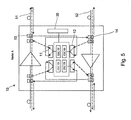
- Figure 5 shows OSU functionality at a node 10 in accordance with an embodiment of the invention.
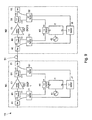
- Figure 6 shows a pair of adjacent nodes with this functionality.
- Figure 6 shows signal flows to measure link 51.
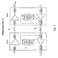
- Figure 7 shows signal flows to measure link 52.
- a first stage measures propagation delay on the first link 51.
- Figure 6 shows signal flows. Dashed lines refer to signals sent in the normal, forward, direction of the OSC on link 51. Dotted lines refer to signals sent in the reverse direction, contrary to normal operation of the OSC on link 51.
- Node A sends a test signal (e.g. a predefined sequence of data) via the OSC channel from the OSC TX of node A to the OSC RX of node B via the second link 52, and subsequently receives the signal via the second link 52, after retransmission by node B.
- Figure 7 shows signal flows. Dashed lines refer to signals sent in the normal, reverse, direction of the OSC along link 52. Dotted lines refer to signals sent in the forward direction, contrary to normal operation of the OSC on link 52.
- Offset ⁇ ⁇ T AB_ 51 - ⁇ ⁇ T AB_ 52
- the offset is the difference in propagation delays between the two links 51, 52.
- Figures 5-7 show additional apparatus at a node 10 to support the measurement.
- An additional switch 11 is provided on the output side of OSC TX and an additional add filter or tap 14 is provided in the path from link 52 to allow a test signal to be switched to link 52.
- An additional combiner 12 is provided on the input side of OSC RX and an additional drop filter 13 is provided in the OSU module to allow a test signal to be received from link 51.
- the OSC operates at a well defined wavelength ⁇ OSC which is different from the wavelength at which the DWDM traffic is transmitted.
- D is a coefficient calculated as in the following, using dispersion and dispersion slope parameters, D ref and S ref (in ps/nm km and ps/nm 2 km respectively), provided in the data sheet of the fibre manufacturer for a reference wavelength ⁇ ref .
- ⁇ 0 ⁇ + ⁇ OSC / 2
- D D ref + S ref * ⁇ 0 - ⁇ ref
- L is the length of the fibre at installation.
- a direct measurement of the delay can be made for a plurality of wavelengths (e.g. three wavelengths ⁇ 1 , ⁇ 2 , ⁇ 3 ), where one of the plurality of wavelengths can be ⁇ OSC , according to the method explained above.
- the fixed laser (OSC TX) is replaced with a tunable laser and add/drop filters are replaced with tunable ones. If tunable lasers are already connected to the equipment, such three wavelengths could be selected among the ones on which the laser can be tuned.
- the delay for an arbitrary different ⁇ can be derived by any suitable technique, such as quadratic interpolation.
- Module 30 which is arranged to perform any of the calculations described above.
- Module 30 can include storage for storing results and parameters used in the calculations.
- Module 30 can control the OSU to perform the sequence of steps of the method.
- the measurements can be sent to another node, such as a management node for calculation.
- the method can use an optical interface transmitting at a wavelength that is blocked by optical amplifiers or other optical equipment located at the two ends of an optical span, so that a measurement is performed on a span-by-span basis.
- Figure 8 shows a pair of adjacent nodes 10 (Node N1, Node N2) of an optical transmission network 4, such as the network of Figure 2 .
- a link 51 connects Node 1 to Node 2 for carrying traffic in a forward direction (N1 - N2) and a link 52 connects Node 1 to Node 2 for carrying traffic in the reverse direction (N2 - N1).
- the two links 51, 52 can have different path lengths, which will incur different propagation delays when signals are sent over these links 51, 52
- Apparatus 20 is provided at each node N1, N2 to measure link asymmetry.
- Propagation delay can be measured on a span-by-span basis between pairs of nodes. Such measurement can be performed at the beginning of the system operation. The method can be performed at other times, e.g. periodically during the lifetime of the network, after equipment at a node has been upgraded or after a fault has occurred, for example.
- the following method can measure the propagation delays introduced by fibre spans 51, 52 and optical nodes 10 in a network so that it is possible to compensate for asymmetries between the two propagation directions. Any node delay (e.g. due to dispersion compensating fibre) can also be measured.
- Figure 8 shows signal flows during the method.
- the method comprises:
- the method can further comprise:
- Measurements acquired at steps 1-4 are used to estimate the difference in propagation delay of the fibre spans 51, 52.
- Measurements acquired at steps 1 A and 3A indicate the delay introduced by the nodes N1 and N2 and can be used to refine the estimation of propagation delay. Measurements can be performed in various orders. For example, measuring delay at node N2 (step 1A) is advantageously performed after step 1A so that node N2 can send the measurement of node delay along with processing delay as part of the step of sending a signal at step 2. This minimizes the number of separate transmissions between node N2 and node N1. However, the measurement of delay at node N2 can be performed at another time, such as after step 2 or 4 or before step 1.
- Measurements at steps 1-4 of the propagation delay between nodes can be made using a dedicated channel transmitted/received by optical interfaces at nodes N1, N2.
- This dedicated channel can be the Optical Supervisory Channel (OSC), or a channel which replaces the traditional Optical Supervisory Channel (OSC) in new networks.
- the wavelength used for measurement will be called an Optical Monitoring Channel (OMC).
- OMC Optical Monitoring Channel
- the frame structure and bit rate details for the data exchanged over this channel for the purpose of correcting for asymmetry may be based on existing standardized format (e.g. as defined in G.709 in case of OTN networks).
- Measurements at steps 1A and 3A of the delay within a node should advantageously occur at a wavelength within the amplification spectrum of the optical amplifier or, more generally, at a wavelength within the operating spectrum of whatever component in the transmission path is being measured.
- all measurements are performed at the same wavelength for best accuracy and to simplify calculations.
- the method can be applied to any kind of node in an optical network, such as optical amplifiers, reconfigurable and fixed OADMs, etc.
- the method can be repeated at multiple (e.g. three) different wavelengths in order to have a complete characterization of the delay vs. the wavelength spectrum. This can be achieved by using a tunable transmitter at the nodes N1, N2 can be used to emit at the different wavelengths.
- the method can perform measurements at a single wavelength and the delay at different wavelengths can be calculated using fibre chromatic dispersion data.
- Figure 9 shows an example of a node architecture to perform the method described above.
- Figure 9 shows a node with an optical amplifier in the transmission path for sake of simplicity, although the node can comprise any kind of optical component, or combination of components.
- Each node has access to an oscillator K1, K2 of sufficient accuracy which is used for measurements.
- switches B1, D1, H1, taps A1, E1 and splitters F1, G1, J1 are provided.
- Switches B1 and D1 allow the delay through the amplifier C1 of node N1 to be measured.
- Switch B1 forwards a test signal from module I1 to the input of the amplifier C1 and switches a signal output by amplifier C1 to the module I1.
- Tap E1 and splitter G1 allow a test signal from module I1 to be applied to link 51 and also allows a test signal received on link 51 to be forwarded to module I1.
- Tap A1 and splitter F1 perform a similar function for test signals sent/received between node N1 and a previous node (not shown).
- switches B2, D2, H2, taps A2, E2 and splitters F2, G2, J2 are provided.
- Switches B2 and D2 allow the delay through the amplifier C2 of node N2 to be measured.
- Switch B2 forwards a test signal from module I2 to the input of the amplifier C2 and switches a signal output by amplifier C2 to the module I2.
- Tap A1 and splitter F1 allow a test signal from module I2 to be applied to link 51 and also allows a test signal received on link 51 to be forwarded to module I2.
- Tap E2 and splitter G2 perform a similar function for test signals sent/received between node N2 and a following node (not shown).
- Figure 9 shows measurement apparatus for implementing steps 1, 2 and 1A of the method described above. Similar measurement apparatus is also provided at each node N1, N2 to implement steps 3, 4 and 3A.
- An optical signal is transmitted from I1 Tx to I2 Rx, through H1 t21 ⁇ G1 ⁇ E1 ⁇ Fibre Span ⁇ A2 ⁇ F2 ⁇ J2
- An optical signal is transmitted from I2 Tx to I2 Rx, through H2 t12 ⁇ F2 ⁇ B2 i12 ⁇ Optical Amplifier ⁇ D2 o12 ⁇ G2 ⁇ J2
- An optical signal is transmitted from I2 Tx to I1 Rx, through H2 t12 ⁇ F2 A2 ⁇ Fibre Span ⁇ E1 ⁇ G1 ⁇ J1
- the scheme in Figure 4 does not contain wavelength-dependent devices and can be used with both single wavelength and tunable transmitters.
- switches B1, D1, B2, D2 can be replaced with tunable or fixed drop filters.
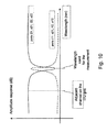
- a transfer function of a suitable filter is shown in Figure 10 .
- the method can be repeated at a set of different wavelengths, with tunable filters tuning to the particular wavelength in use at each point in time.
- OMC Optical Monitoring Channel
- the signal arrives in OMC RX of I2 with a delay of ⁇ T 12 due to the propagation time in the fibre span from node A to node B.
- ⁇ T 12 is not measurable by node B because node A and B does not have a common time reference.
- the OMC Module in Node 2 sends a second predefined sequence of data in this case via the relevant delay components of Node 2 (i.e. Optical Amplifier with the related DCF) and receives a delayed copy of the same sequence. In this way is able to measure the delay ⁇ T2 added by its Optical Amplifier (step 1A)
- Node 2 introduces an additional delay ⁇ T 2proc , mainly due to signal processing in the OMC module, and then sends a response to 1 using its TX module in I2 (step 2).
- the data streaming from node 2 to node 1 runs on the same fibre and contains ⁇ T2 proc and ⁇ T2 values.
- the signal arrives in OMC RX of node 1 with a delay of ⁇ T 21 introduced by the propagation time in the fibre span from node 2 to node 1.
- T 1 T 0 + ⁇ ⁇ T 12 + ⁇ ⁇ T 2 ⁇ proc + ⁇ ⁇ T 21
- Node N1 sends a test signal (e.g. a predefined sequence of data) via the OMC channel to node N2 via the second link 52, and subsequently receives a reply to the signal via the second link 52, after retransmission by node B.
- a test signal e.g. a predefined sequence of data
- Offset ⁇ ⁇ T 51 - ⁇ ⁇ T 52
- the offset is the difference in propagation delays between the two links 51, 52.
- a sequence of messages similar to the IEEE 1588 Pdelay _ Req and Pdelay_Resp could be used to obtain measurement of propagation delay over a single fibre, as shown in Figure 12 .
- all nodes involved in this process shall implement an oscillator with sufficient accuracy. If the network supports synchronous Ethernet, access to an accurate reference will be available. If there is no accurate frequency reference available on the line (e.g. as normally is the case for OTN networks), the free-running accuracy of the oscillator in the node involved in the measurement should be at least within a few ppm (e.g. similar to the accuracy that can be provided by the oscillator used to implement the G.813 or G.8262 clocks). In fact assuming the data exchange is completed in 1 ms, in the end the error introduced by the oscillator would be in the order of few ns and should still be acceptable (e.g. 4.6 ppm over 1 ms would result in 4.6 ns).
- the OMC operates at a well-defined wavelength ⁇ OMC which is different from the wavelength at which the DWDM traffic is transmitted.
- ⁇ OMC estimated in (2) is valid at ⁇ OMC : additional calculations are required to evaluate the propagation delay related to the wavelength(s) really used for traffic.
- fibre dispersion parameters could be experimentally estimated running the aforementioned steps at three different wavelengths, e.g. by using tunable lasers, Several implementations are possible for the setup in figure 1 , based on optical switches or fixed or tunable add drop filters. Depending on the implementation, in service operation is possible for all the steps of the method.
- the method provides a propagation delay ⁇ f for the forward link 51 and a reverse propagation delay ⁇ r for the reverse link 52.
- the difference ( ⁇ f - ⁇ r ) can be used in the evaluation of the delay asymmetry to be used in the time recovering process.
- the delayAsymmetry parameter defined in IEEE1588 is half of the difference ( ⁇ f - ⁇ r ). Note that according to IEE15888 the delayAsymmetry parameter is defined to be positive when the master-to-slave or responder-to-requestor propagation time is longer than the slave-to-master or requestor-to-responder propagation time.
- the compensation can be performed locally where the PTP flow is processed.
- IEEE1588 is processed outside the transport network (e.g. at the borders of the OTN network) some means is provided in order to make the asymmetry compensation values available at the point in the network where the PTP packets are processed.
- the asymmetry compensation is a process only required only at start up, or during rearrangements in the network, there would not be particular timing constraints for the distribution of these data.
- the data could be distributed via the control plane.
- D is a coefficient calculated as in the following, using dispersion and dispersion slope parameters, D ref and S ref (in ps/nm km and ps/nm 2 km respectively), provided in the data sheet of the fibre manufacturer for a reference wavelength ⁇ ref .
- ⁇ 0 ⁇ + ⁇ OMC / 2
- D D ref + S ref * ⁇ 0 - ⁇ ref L is the length of the fibre at installation.
- the delay for an arbitrary different ⁇ can be derived by any suitable technique, such as quadratic interpolation.
- a more accurate correction might be done by using the Sellmeier equations for the fibre chromatic dispersion (see G.650 and G.652).
- Measurement module 20 is arranged to perform any of the calculations described above. Module 20 can include storage for storing results and parameters used in the calculations. As an alternative to locally performing calculations at the node, the measurements can be sent to another node, such as a management node for calculation.
- Embodiments have an advantage of not requiring manual compensation for asymmetries in the fibre. This process is currently only handled manually and the related costs might become unbearable once the IEEE 1588 technology is implemented in the telecom networks.
- the apparatus provided at node N1 supports measurement of propagation delay between nodes N1 and N2 and also supports measurement of propagation delay between node N1 and a previous node (not shown). This allows a single module I1 to be used for both spans. In an alternative embodiment, there is apparatus dedicated to each span (i.e. just to measuring node N1-N2).
- the apparatus provided at node N1 supports measurement of propagation delay along link 51 between nodes N1 and N2. Additional apparatus is provided at node N1 to support measurement of propagation delay along link 52 between nodes N1 and N2.
- apparatus with a single module I1 can selectively connect to link 51 and to link 52.
- apparatus with a single module I1 can selectively connect to any of: link 51; link 52; the span between nodes N1-N2; and the span between node N1 and a previous node.
- this shows a node 10 with an input 11, an output 12 and a component 15 such as an optical amplifier in the transmission path connecting the input 11 and output 12.
- Delay incurred by the component 15 at node N1 can be calculated as part of the measurement process between node N0 (the node preceding N1) and N1.
- Figure 11 shows a node such as an OADM with an input stage 110 and an output stage 120 interconnected by a switch 115. Any delay incurred by components 122 in the output stage of the node can be calculated by an additional measurement step using the signal path 37.
- Delay incurred by the component 112 at node 200 can be calculated as part of the measurement process between the preceding node and node 200, where the "output port" of step 1A can be an internal output port 113 of node 100.
- any delay incurred by components at each of an input stage and an output stage of the node can be calculated.
- asymmetry is evaluated between each pair of fibres used to exchange timing information, and can include delay incurred at any part of a node.
- the measurements for asymmetry compensation can be performed at start up of the network or during/following rearrangements of the network (in case these rearrangements would require the updating of the asymmetry compensation).
- a wavelength that carries traffic can be used for the measurements.
- some of the Overhead RES bytes can be used in case the measurement is made by a node that terminates that frame (e.g. in case of OTN, the GCC bytes in the OTN overhead).
- To perform measurements in the opposite direction as traffic flow over the link e.g.
- one of the lambdas that is used in the other fibres could be used (but this may not always be desired due to interferences and a new lambda different from any of the lambdas used for traffic should be used).
- the data could be carried in the overhead (e.g. GCC bytes in the OTN overhead).
- Figure 13A shows signalling to obtain a calibration of the forward propagation delay d f and signalling to obtain a calibration of the reverse propagation delay d r .
- Wavelength ⁇ 1 can be the wavelength which carries the OSC, a dedicated measurement channel (such as the OMC described above or a traffic channel dedicated to measurement), or a traffic channel which is used to make measurements while carrying traffic. If the measurement process uses a wavelength which is different from the wavelength at which a value of propagation delay is required, then an adjustment can be made to compensate for different optical properties at the two wavelengths. For example, in Figure 13A all measurements are performed at a wavelength ⁇ 1 and the wavelength at which a value of propagation delay is required is a different wavelength, say ⁇ n. The value of propagation delay calculated at wavelength ⁇ 1 can be compensated to obtain a value at the required wavelength ⁇ n.
- Figure 13B shows an example situation where measurements on link 51 are made at a wavelength ⁇ 1 and measurements on link 52 are made at a wavelength ⁇ 2. The measurements can be compensated to account for this difference.
- Figure 13A if a value of propagation delay is required at a wavelength which is different from the ones used to make measurements, then a further compensatory adjustment can be made.
- Figure 13C shows another example situation where different wavelengths are used. A measurement in the forward direction (A-B) is made at wavelength ⁇ 1 and a measurement in the reverse direction (B-A) is made at wavelength ⁇ 2. The propagation delay for link 51 can be adjusted to compensate for the different wavelengths used to make the measurements.
- wavelengths ⁇ 1, ⁇ 2 can be the wavelength which carries the OSC, a dedicated measurement channel (such as the OMC described above or a traffic channel dedicated to measurement), or a traffic channel which is used to make measurements while carrying traffic.
- the first method uses a fixed wavelength transmitter (e.g. using the OSC/OMC), and uses chromatic dispersion data (e.g. known from optical fibre data-sheet) to compensate the measurement for the wavelength of interest.
- the second method is based on direct delay measurement at a set of three (or more) different wavelengths (e.g. using a tuneable transmitter). This allows propagation delay to be calculated at any desired wavelength by quadratic interpolation between the values obtained at the set of different wavelengths.
- the compensation of asymmetry due to the use of different wavelength is obtained by calculating the group delay applicable to wavelengths used in the forward and in the reverse direction.
- the evaluation of the refractive indexes can be done either using known chromatic dispersion data (e.g. from the optical fibre data-sheet) or, in case the dispersion in unknown, making a direct delay measurement at three different wavelengths (the refractive index for an arbitrary wavelength can then be derived by quadratic interpolation).
- Step 14 shows a method for measuring asymmetry in propagation delay of first and second links which connect a first node to a second node of a communication network.
- Step 101 comprises measuring a round trip delay of the first link. This can comprise a step 102 of transmitting a test signal from the first node to the second node over the first link and receiving a reply to the test signal from the second node over the first link. Additionally, step 103 can receive a measure of processing delay, performed by the second node. If different wavelengths have been used for the test signal and reply at step 102, step 104 can compensate for this.
- Step 105 comprises measuring a round trip delay of the second link.
- a method for measuring asymmetry in propagation delay of first and second links which connect nodes of a communication network comprises transmitting a test signal to the second node over the first link and measuring a first link round trip delay taken to receive the test signal from the second node over the first link.
- the method further comprises transmitting a test signal to the second node over the second link and measuring a second link round trip delay taken to receive the test signal from the second node over the second link.
- the method further comprises determining a difference in the propagation delay of the first link with respect to the second link using the first link round trip delay and the second link round trip delay.
- the communication network can be an optical network.
- the test signal can be transmitted over an Optical Supervisory Channel of the optical network.
- the method can determine a difference in the propagation delay of the first link with respect to the second link at a first wavelength (e.g. a wavelength used to carry the OSC) and can then determine a difference in the propagation delay of the first link with respect to the second link at a second, different, wavelength, using the determined difference in the propagation delay at the first wavelength.
- the second wavelength can be a wavelength used to carry traffic.
- the method can use known parameters of the link such as: dispersion , dispersion slope.
- the method can be performed at a plurality of different wavelengths, to give a value for the difference in the propagation delay of the first link with respect to the second link at each of a plurality of different wavelengths.
- One of the plurality of wavelengths can be a wavelength used to carry the OSC.
- the method can comprise determining a difference in the propagation delay of the first link with respect to the second link at a further wavelength, using the values of difference in propagation delay calculated at the plurality of wavelengths. Any suitable mathematical technique, such as quadratic interpolation, can be used.
- the determined difference in the propagation delay of the first link with respect to the second link can be used by any layer using the communication network.
- An aspect provides a node of a communication network comprising an interface to a first link and an interface to a second link.
- the first link and second link connect the node to a second node.
- the node is arranged to transmit a test signal to the second node over the first link and measure a first link round trip delay taken to receive the test signal from the second node over the first link.
- the node is further arranged to transmit a test signal to the second node over the second link and measure a second link round trip delay taken to receive the test signal from the second node over the second link.
- the node can be arranged to determine a difference in the propagation delay of the first link with respect to the second link using the first link round trip delay and the second link round trip delay.
- the node can be a node of an optical communication network.
- the test signal can be transmitted over an Optical Supervisory Channel of the optical communication network.
- the node can comprise a transmitter which is arranged to selectively transmit on the first link and the second link.
- the node can comprise a receiver which is arranged to receive from the first link and the second link.
- the first link is normally used to send traffic, and the node can comprise a drop function for extracting a wavelength carrying the test signal from the first link.
- the second link is normally used to receive traffic, and the node can comprise an add function for adding a wavelength carrying the test signal to the second link.
Landscapes
- Engineering & Computer Science (AREA)
- Computer Networks & Wireless Communication (AREA)
- Signal Processing (AREA)
- Physics & Mathematics (AREA)
- Electromagnetism (AREA)
- Environmental & Geological Engineering (AREA)
- Data Exchanges In Wide-Area Networks (AREA)
- Optical Communication System (AREA)
- Monitoring And Testing Of Transmission In General (AREA)
Description
- This invention relates to a communication network, such as an optical communication network, and to determining asymmetries between links of the network.
- There are a number of applications requiring accurate frequency and/or time synchronization references in order to properly operate, for example mobile technologies such as Global System for Mobile Communications (GSM), Wideband Code Division Multiple Access (W-CDMA) and in the future Long Term Evolution (LTE). In case of frequency synchronization the traditional solution is to get synchronization from a synchronous stream of data, as for instance in case of Time-Division Multiplexed (TDM) based networks, but the migration of networks from TDM to packet-based technologies (such as Ethernet) requires a different approach.
- One solution is to use a packet based method, where the timing is carried across a packet network by sending packets containing timestamp information. The timestamps are generated by a master (server) that has access to an accurate reference, such as Global Positioning System (GPS). This is shown in
US 2007/0223537 . - Each receiving system can run an algorithm that recovers the timing based on adaptive clock recovery methods, e.g. by comparing the local timing with the inter-arrival times of the packets (see ITU-T G.8261). The accuracy of the recovered clock is therefore affected by variable delays in the network, and one of the key requirements of the algorithm is to filter out the packet delay variation.
- When time synchronization is requested, a two-way timing protocol is required (e.g. Network Time Protocol (NTP) or Precision Time Protocol (PTP)). The transfer delay from master to slave is calculated. One fundamental assumption with this approach is that the delay from master to slave and from slave to master shall be identical. This means that any asymmetry in the network would significantly impact the performance of the delivered time synchronization reference.
- As an example, the scheme shown in
Figure 1 relates to the time distribution via the PTP protocol (IEEE 1588). Similar discussion applies with other protocols such as NTP. The message exchange pattern is: - The master sends a Sync message to the slave and notes the time, t1, at which it was sent.
- The slave receives the Sync message and notes the time of reception, t2.
- The master conveys to the slave the timestamp t1 by:
- ∘ Embedding the timestamp t1 in the Sync message. This requires some sort of hardware processing for highest accuracy and precision, or
- ∘ Embedding the timestamp t1 in a Follow_Up message.
- The slave sends a Delay_Req message to the master and notes the time, t3, at which it was sent.
- The master receives the Delay_Req message and notes the time of reception, t4.
- The master conveys to the slave the timestamp t4 by embedding it in a Delay_Resp message.
- At the conclusion of this exchange of messages, the slave possesses all four timestamps. These timestamps may be used to compute the offset of the slave's clock with respect to the master and the mean propagation time of messages between the two clocks, which in
Figure 1 is the mean of t-ms and t-sm. The slave shall synchronize to its master via the minimization of the <offsetFromMaster> value computed by the slave. The time error between a slave and master ordinary or boundary clock (<offsetFromMaster>) is defined as: - <offsetFromMaster> = <Time on the slave clock> - <Time on the master clock> where all times are measured at the same instant.
- In particular, the <offsetFromMaster> value shall be computed by the slave as follows:
- If a Follow_Up message will not be received, then
- <offsetFromMaster> = (t2 - t1) - <meanPathDelay> - correctionField of Sync message.
- If a Follow_Up message will be received, then
- <offsetFromMaster> = (t2 - t1) - <meanPathDelay> - correctionField of Sync message - correctionField of Follow_Up message
- The nominal value of the <meanPathDelay> is computed as
- <meanPathDelay> = [(t2 - t1) + (t4 - t3)]/2 = [(t2 - t3) + (t4 - t1)]/2
- The scheme is slightly different in case of Peer-to-Peer Transparent clocks where the Path delay is calculated at each hop and included in the correction field of the sync message (or Follow-up message in case of 2-steps clock) in addition to the latency.
- From the above description it can be seen that the computation of offset and propagation time assumes that the master-to-slave and slave-to-master propagation times are equal. Any asymmetry in propagation time introduces an error in the computed value of the clock offset. The computed mean propagation time differs from the actual propagation times due to the asymmetry.
- If the delay asymmetry of the path connected to the ingress port is known, the corrections can be made as specified by the PTP protocol.
- In particular IEEE 1588 defines the attribute "delayAsymmetry" as follows for t-ms and t-sm:
- tms = <meanPathDelay> + delayAsymmetry
- tsm = <meanPathDelay> - delayAsymmetry
- In other words, delayAsymmetry is defined to be positive when the master-to-slave or responder-to requestor propagation time is longer than the slave-to-master or requestor-to-responder propagation time.
- In order to handle the packet delay variation and the asymmetries in the network the "Boundary Clock" or "Transparent Clock" functions have been specified by IEEE 1588.
- The IEEE 1588 transparent clock is a function that provides a means of measuring the delay that has been added by the network element and of measuring the delays on links connected to the network element. The end-equipment can use this information to recover the time reference.
- The boundary clock, by contrast, terminates and regenerates timestamp packets. While any asymmetry in the node is effectively removed by means of the HW timestamping at the ingress and egress ports, still asymmetries may be present in the links connecting two nodes.
- This may happen in case of forward and reverse traffic (and therefore PTP flow) in the same fibre but over different wavelength (e.g. WDM-PON) or in case of forward and reverse traffic in two different fibres (and using the same wavelength), therefore with different transmission characteristics and different length.
- The accuracy of phase/time synchronization required by mobile networks is typically in the order of microseconds. This implies that the requirements for technologies such as IEEE 1588v2 to provide precise phase/time over transport networks require that the handling of any source for asymmetry is controlled at the ns level.
- In order to remove the asymmetries in the links, currently the only solution is to manually calibrate the links. If the delay asymmetry of the path connected to the ingress port is known, the corrections can be made as specified by the PTP protocol.
- This must be performed node-by-node and can be an extremely costly and time consuming process. Moreover, at any change in the network (e.g. adding transmission equipments) the compensation has to be updated. This can be a too complex and costly task creating a significant obstacle in the deployment of the IEEE1588 technology.
- A method is described for measuring asymmetry in propagation delay of first and second links which connect a first node to a second node of a communication network, as defined in
claim 1. - Gurewitz O et al "Estimating one-way delays from cyclic-path delay measurements", Proceedings IEEE INFOCOM 2001, Conference on computer communications, twentieth annual joint conference of the IEEE computer and communications society, Piscat, Vol. 2, 22 April 2001, describes estimation of one-way delays from cyclic path delay measurements that do not require any kind of synchronization among the nodes of the network. The cyclic-path delays are expressed in terms of one-way delay variables.
- The method comprises measuring a round trip delay of the first link. The round trip delay can be measured by transmitting a test signal from the first node to the second node over the first link and receiving a reply to the test signal from the second node over the first link.
- The method further comprises measuring a round trip delay of the second link. The round trip delay can be measured by transmitting a test signal to the second node over the second link and receiving a reply to the test signal from the second node over the second link.
- The method further comprises determining a difference in the propagation delay of the first link with respect to the second link using the measured round trip delays of the first link and the second link.
- The method can comprise measuring a processing delay incurred at the second node between receiving the test signal and sending a reply to the test signal. The method can use the processing delay when determining a difference in the propagation delay of the first link with respect to the second link.
- The method can also comprise a step of measuring a delay incurred in a transmission path at the second node. The method can also comprise a step of measuring delay incurred in a transmission path at the first node. The measured delay at a node can be delay caused by a component such as an optical amplifier, dispersion compensation fibre (DCF) or any other component in the transmission path which may affect the calculation of difference in propagation delay.
- Measurements can be made at any suitable wavelength. Measurements can be performed using a dedicated wavelength, such a wavelength dedicated to measurement purposes. This wavelength can be the wavelength used to carry the Optical Supervisory Channel (OSC) or any other suitable wavelength outside a transmission band of an optical amplifier or other optical component at a node. It is also possible to perform measurements at a wavelength within the transmission band of an optical amplifier, such as one or more of the wavelengths normally used to carry traffic channels. The measurements can be performed while the wavelength is carrying traffic, such as by using overhead information.
- The method can determine a difference in the propagation delay of the first link with respect to the second link at a first wavelength and can then determine a difference in the propagation delay of the first link with respect to the second link at a second, different, wavelength, using the determined difference in the propagation delay at the first wavelength. The second wavelength can be a wavelength used to carry traffic. The method can use known parameters of the link such as: dispersion, dispersion slope.
- In an alternative, the method can be performed at a plurality of different wavelengths, to give a value for the difference in the propagation delay of the first link with respect to the second link at each of a plurality of different wavelengths. The method can comprise determining a difference in the propagation delay of the first link with respect to the second link at a further wavelength, using the values of difference in propagation delay calculated at the plurality of wavelengths. Any suitable mathematical technique, such as quadratic interpolation, can be used.
- The determined difference in the propagation delay of the first link with respect to the second link can be used by any layer using the communication network.
- The communication network can be an optical network.
- According to an embodiment, at least one of the measuring steps is performed at a wavelength that is normally used to carry traffic while the wavelength is carrying traffic. This can be achieved by using overhead data. In the case of the Optical Transport Network, suitable overhead data are Reserved (RES) bytes of the overhead or General Communication Channel (GCC) bytes of the overhead.
- An aspect provides apparatus at a node of a communication network to perform any of the steps of the method. The apparatus is arranged to measure a round trip delay of the first link. The round trip delay can be measured by transmitting a test signal from the first node to the second node over the first link and receiving a reply to the test signal from the second node over the first link. The test signal can be applied to the first link by a tap, combiner, switch or any suitable mechanism. Similarly, a reply to the test signal can be applied to the first link by a tap, combiner, switch or any suitable mechanism.
- The apparatus is arranged to measure a round trip delay of the second link. The round trip delay can be measured by transmitting a test signal to the second node over the second link and receiving a reply to the test signal from the second node over the second link. The test signal can be applied to the second link by a tap, combiner, switch or any suitable mechanism. Similarly, a reply to the test signal can be applied to the second link by a tap, combiner, switch or any suitable mechanism.
- The apparatus further comprises a module for determining a difference in the propagation delay of the first link with respect to the second link using the measured round trip delays of the first link and the second link.
- The apparatus can also comprise a module for measuring a delay incurred in a transmission path at the node. The apparatus can comprise a first element to apply a test signal from a module to the transmission path and a second element to forward the test signal from the transmission path to the module. The first and second elements can be positioned at an input to a transmission interface at a node and at an output of a transmission interface at a node, or at respective sides of one or more components in the transmission path which may incur a delay, such as at respective sides of an optical amplifier or other component in the transmission path. The first and second elements can be switches or filters.
- The node can be a node of an optical communication network.
- The functionality described here can be implemented in hardware, software executed by a processing apparatus, or by a combination of hardware and software. The processing apparatus can comprise a computer, a processor, a state machine, a logic array or any other suitable processing apparatus. The processing apparatus can be a general-purpose processor which executes software to cause the general-purpose processor to perform the required tasks, or the processing apparatus can be dedicated to perform the required functions. Another aspect of the invention provides machine-readable instructions (software) which, when executed by a processor, perform any of the described methods. The machine-readable instructions may be stored on an electronic memory device, hard disk, optical disk or other machine-readable storage medium. The machine-readable instructions can be downloaded to the storage medium via a network connection.
-
Figure 2 shows anoptical communication network 2 comprisingnodes 10.Adjacent nodes 10 of the network are connected bylinks 5. A separate link can be provided for each direction of communication: a first link for carrying traffic in the forward direction of communication and a second link for carrying traffic in the reverse direction of communication. Each link can be a separate fibre which can follow a physically separate path. - An embodiment of a system and method for measuring asymmetry between nodes will now be described with reference to
Figures 3 to 7 . This embodiment uses an Optical Supervisory Channel (OSC). -
Figures 3 and4 show a pair of adjacent nodes 10 (Node A, Node B) of theoptical transmission network 2. Alink 51 connects Node A to Node B for carrying traffic in a forward direction (A-B) and alink 52 connects Node A to Node B for carrying traffic in a reverse direction (B-A). The twolinks links -
Figures 3 and4 show conventional apparatus provided at nodes to support an Optical Supervisory Channel (OSC). The OSC is an additional wavelength λOSC, usually outside the EDFA amplification band, (at 1510 nm, 1620 nm, 1310 nm or another proprietary wavelength) which carries information about the DWDM optical signal as well as remote conditions at the optical terminal or amplifier site. It is also normally used for remote software upgrades and network management information. The OSC signal structure is vendor specific even if the ITU standard suggests using an OC-3 signal structure. Unlike the 1550 nm band client signal-carrying wavelengths, the OSC is terminated at intermediate amplifier sites, where it receives local information before retransmission. -
Figure 4 shows two nodes connected by two fibre spans 51, 52 (one for each direction). The dashed lines depict the OSC between the two nodes during normal operation. OSC is dropped and added at each site using filters and RX/TX modules. Each intermediate node is equipped with a unit devoted to OSC termination. This unit can be called an Optical Supervisory Unit (OSU). A Dual OSU card can be provided to support an OSC in directions. - According to an embodiment of the invention, propagation delay is measured on a span-by-span basis. Such measurement can be performed at the beginning of the system operation and so the bandwidth reserved and the hardware installed for OSC can be used at the begin of network life without interfering with the following normal OSC operation. The method can be performed at other times, e.g. periodically during the lifetime of the network or after equipment at a node has been upgraded.
- In particular the principle is based on the round trip delay calculation as for instance used with protocols like Network Time Protocol (NTP) and Precision Time Protocol (PTP).
-
Figure 5 shows OSU functionality at anode 10 in accordance with an embodiment of the invention.Figure 6 shows a pair of adjacent nodes with this functionality.Figure 6 shows signal flows to measurelink 51.Figure 7 shows signal flows to measurelink 52. - A method according to an embodiment of the invention will now be described. A first stage measures propagation delay on the
first link 51.Figure 6 shows signal flows. Dashed lines refer to signals sent in the normal, forward, direction of the OSC onlink 51. Dotted lines refer to signals sent in the reverse direction, contrary to normal operation of the OSC onlink 51. - ▪ At the time T0 a test signal (e.g. a predefined sequence of data) is sent via the OSC channel from the OSC TX of node A to the OSC RX of node B via the
first link 51. - ▪ The signal arrives in OSC RX of node B with a delay of ΔTAB due to the propagation time in the fibre span from node A to node B. At this stage ΔTAB is not measurable by node B because node A and B does not have a common time reference.
- ▪ The OSU module, in node B, introduces an additional processing delay ΔTB and then sends a response to A, via the
first link 51, using its TX module. The data streaming from node B to node A runs on thesame fibre 51 and contains the ΔTB figure. - ▪ The signal arrives in OSC RX of node A with a delay of ΔTBA introduced by the propagation time in the fibre span from node B to node A.
- ▪ Node A now mark as T1 the time in which the signal from node B is received. That is:

- ▪ Note that T0 and T1 are measured directly by node A while ΔTB has been measured by node B and sent to node A embedded in the signal sent back to A. In addition it is possible to assume that ΔTAB = ΔTBA and so node A can calculate the desired propagation delay at the wavelength of operation of the OSC channel λOSC:

- The method is then repeated for the
second link 52. Node A sends a test signal (e.g. a predefined sequence of data) via the OSC channel from the OSC TX of node A to the OSC RX of node B via thesecond link 52, and subsequently receives the signal via thesecond link 52, after retransmission by node B.Figure 7 shows signal flows. Dashed lines refer to signals sent in the normal, reverse, direction of the OSC alonglink 52. Dotted lines refer to signals sent in the forward direction, contrary to normal operation of the OSC onlink 52. - The two measurement stages described above provide:


where
- From this, the offset (asymmetry) can be computed:

- The offset is the difference in propagation delays between the two
links -
Figures 5-7 show additional apparatus at anode 10 to support the measurement. Anadditional switch 11 is provided on the output side of OSC TX and an additional add filter or tap 14 is provided in the path fromlink 52 to allow a test signal to be switched to link 52. Anadditional combiner 12 is provided on the input side of OSC RX and anadditional drop filter 13 is provided in the OSU module to allow a test signal to be received fromlink 51. - The OSC operates at a well defined wavelength λOSC which is different from the wavelength at which the DWDM traffic is transmitted. The value of τOSC estimated in (2) is valid at λOSC. Additional calculations are required to refer the propagation delay to the wavelength(s) used for traffic. If λ represents one of the (e.g. 80) traffic-carrying wavelengths of the ITU grid, we have:

- Where D is a coefficient calculated as in the following, using dispersion and dispersion slope parameters, Dref and Sref (in ps/nm km and ps/nm2 km respectively), provided in the data sheet of the fibre manufacturer for a reference wavelength λref.


- L is the length of the fibre at installation.
- Finally the propagation delay at λ is:

- If the dispersion in unknown and it is required to apply the proposed method to an arbitrary λ, a direct measurement of the delay can be made for a plurality of wavelengths (e.g. three wavelengths λ1, λ2, λ3), where one of the plurality of wavelengths can be λOSC, according to the method explained above. Advantageously, the fixed laser (OSC TX) is replaced with a tunable laser and add/drop filters are replaced with tunable ones. If tunable lasers are already connected to the equipment, such three wavelengths could be selected among the ones on which the laser can be tuned. The delay for an arbitrary different λ can be derived by any suitable technique, such as quadratic interpolation.
- Referring again to
Figure 5 , this shows amodule 30 which is arranged to perform any of the calculations described above.Module 30 can include storage for storing results and parameters used in the calculations.Module 30 can control the OSU to perform the sequence of steps of the method. As an alternative to locally performing calculations at the node, the measurements can be sent to another node, such as a management node for calculation. - As an alternative to performing measurements using the OSC, the method can use an optical interface transmitting at a wavelength that is blocked by optical amplifiers or other optical equipment located at the two ends of an optical span, so that a measurement is performed on a span-by-span basis.
- Another embodiment of a system and method for measuring asymmetry between nodes will now be described with reference to
Figures 8 to 12 .Figure 8 shows a pair of adjacent nodes 10 (Node N1, Node N2) of anoptical transmission network 4, such as the network ofFigure 2 . Alink 51 connectsNode 1 toNode 2 for carrying traffic in a forward direction (N1 - N2) and alink 52 connectsNode 1 toNode 2 for carrying traffic in the reverse direction (N2 - N1). The twolinks links Apparatus 20 is provided at each node N1, N2 to measure link asymmetry. - Propagation delay can be measured on a span-by-span basis between pairs of nodes. Such measurement can be performed at the beginning of the system operation. The method can be performed at other times, e.g. periodically during the lifetime of the network, after equipment at a node has been upgraded or after a fault has occurred, for example.
- The following method can measure the propagation delays introduced by fibre spans 51, 52 and
optical nodes 10 in a network so that it is possible to compensate for asymmetries between the two propagation directions. Any node delay (e.g. due to dispersion compensating fibre) can also be measured.Figure 8 shows signal flows during the method. - The method comprises:
- measuring round-trip propagation delay over
link 51 by:- 1. Sending a signal (31) from an output port of node N1 to an input port of a subsequent node N2 in the same propagation direction to the channel wavelengths on
link 51. - 2. Sending a signal (32) from an input port of node N2 to an output port of the previous node N1, in the opposite propagation direction to the channel wavelengths on link 51 (i.e. opposite to the normal direction of link 51).
Processing delay at node N2 can be measured by node N2 and sent to node N1. Processing delay is the delay between receiving the test signal at node N2 and sending a signal atstep 2.
- 1. Sending a signal (31) from an output port of node N1 to an input port of a subsequent node N2 in the same propagation direction to the channel wavelengths on
- measuring round-trip propagation delay over
link 52 by:- 3. Sending a signal (33) from an input port of node N1 to an output port of a subsequent node N2 in the opposite propagation direction to the channel wavelengths on link 52 (i.e. opposite to the normal direction of link 52).
- 4. Sending a signal (34) from an output port of node N2 to an input port of the previous node N1, in the same propagation direction as the channel wavelengths on
link 52.
- The method can further comprise:
- measuring delay at node N2 by:
- 1A. Sending a signal (35) from an input port of node N2 to an output port of the same node N2, in the same propagation direction as the channel wavelengths. The measured delay at node N2 can be sent to node N1.
- measuring delay at node N1 by:
- 3A. Sending a signal (36) from an input port of node N1 to an output port of the same node N1, in the same propagation direction as the channel wavelengths.
- Measurements acquired at steps 1-4 are used to estimate the difference in propagation delay of the fibre spans 51, 52. Measurements acquired at steps 1 A and 3A indicate the delay introduced by the nodes N1 and N2 and can be used to refine the estimation of propagation delay. Measurements can be performed in various orders. For example, measuring delay at node N2 (step 1A) is advantageously performed after step 1A so that node N2 can send the measurement of node delay along with processing delay as part of the step of sending a signal at
step 2. This minimizes the number of separate transmissions between node N2 and node N1. However, the measurement of delay at node N2 can be performed at another time, such as afterstep step 1. - Measurements at steps 1-4 of the propagation delay between nodes can be made using a dedicated channel transmitted/received by optical interfaces at nodes N1, N2. This dedicated channel can be the Optical Supervisory Channel (OSC), or a channel which replaces the traditional Optical Supervisory Channel (OSC) in new networks. The wavelength used for measurement will be called an Optical Monitoring Channel (OMC). The frame structure and bit rate details for the data exchanged over this channel for the purpose of correcting for asymmetry, may be based on existing standardized format (e.g. as defined in G.709 in case of OTN networks).
- Measurements at steps 1A and 3A of the delay within a node should advantageously occur at a wavelength within the amplification spectrum of the optical amplifier or, more generally, at a wavelength within the operating spectrum of whatever component in the transmission path is being measured.
- Advantageously, all measurements are performed at the same wavelength for best accuracy and to simplify calculations. However, it is possible to perform round trip measurements at one wavelength, perform node delay measurements at another wavelength, and apply a correction factor to one of the types of measurement.
- The method can be applied to any kind of node in an optical network, such as optical amplifiers, reconfigurable and fixed OADMs, etc.
- The method can be repeated at multiple (e.g. three) different wavelengths in order to have a complete characterization of the delay vs. the wavelength spectrum. This can be achieved by using a tunable transmitter at the nodes N1, N2 can be used to emit at the different wavelengths.
- Alternatively, the method can perform measurements at a single wavelength and the delay at different wavelengths can be calculated using fibre chromatic dispersion data.
-
Figure 9 shows an example of a node architecture to perform the method described above.Figure 9 shows a node with an optical amplifier in the transmission path for sake of simplicity, although the node can comprise any kind of optical component, or combination of components. - Each node has access to an oscillator K1, K2 of sufficient accuracy which is used for measurements.
- At node N1, switches B1, D1, H1, taps A1, E1 and splitters F1, G1, J1 are provided. Switches B1 and D1 allow the delay through the amplifier C1 of node N1 to be measured. Switch B1 forwards a test signal from module I1 to the input of the amplifier C1 and switches a signal output by amplifier C1 to the module I1. Tap E1 and splitter G1 allow a test signal from module I1 to be applied to link 51 and also allows a test signal received on
link 51 to be forwarded to module I1. Tap A1 and splitter F1 perform a similar function for test signals sent/received between node N1 and a previous node (not shown). - At node N2, switches B2, D2, H2, taps A2, E2 and splitters F2, G2, J2 are provided. Switches B2 and D2 allow the delay through the amplifier C2 of node N2 to be measured. Switch B2 forwards a test signal from module I2 to the input of the amplifier C2 and switches a signal output by amplifier C2 to the module I2. Tap A1 and splitter F1 allow a test signal from module I2 to be applied to link 51 and also allows a test signal received on
link 51 to be forwarded to module I2. Tap E2 and splitter G2 perform a similar function for test signals sent/received between node N2 and a following node (not shown). -
Figure 9 shows measurement apparatus for implementingsteps steps - The following steps correspond to those described above.
- An optical signal is transmitted from I1 Tx to I2 Rx, through H1 t21 → G1 → E1 → Fibre Span → A2 → F2 → J2
- An optical signal is transmitted from I2 Tx to I2 Rx, through H2 t12 → F2 →B2 i12 → Optical Amplifier →D2 o12 → G2 → J2
- An optical signal is transmitted from I2 Tx to I1 Rx, through H2 t12 → F2 A2 → Fibre Span → E1 → G1 → J1
- The states of the switches (on=closed, off= open) are summarized below:
H1 B1 D1 H2 B2 D2 Regular t11 off i11 off o21 on t12 off i12 off o22 on operation t21 on i21 on o11 off t22 on i22 on o12 off Step 1t11 off i11 on o11 on(1) t12 off i12 on o12 on(1) (N1-N2) t21 on i21 off o21 off t22 on i22 off o22 off Step 1A t11 on i11 on o21 off t12 on i12 on o22 off (delay at N2) t21 off i21 off o11 on t22 off i22 off o12 on Step 2t11 on i11 off o21 off t12 on i12 off o22 off (N2-N1) t21 off i21 on o11 on t22 off i22 on o12 on (1) The signal going from o11 into the optimal amplifier C1 is blocked by an optical isolator (not shown in the figure) present at the output port of C1. Similar considerations hold for different types of nodes. - The scheme in
Figure 4 does not contain wavelength-dependent devices and can be used with both single wavelength and tunable transmitters. - To allow in-service operation, switches B1, D1, B2, D2 can be replaced with tunable or fixed drop filters. A transfer function of a suitable filter is shown in
Figure 10 . As described above, the method can be repeated at a set of different wavelengths, with tunable filters tuning to the particular wavelength in use at each point in time. - The term Optical Monitoring Channel (OMC) will be used to refer to the wavelength at which a measurement is made. With reference to
Figure 9 : - At the time To a predefined sequence of data is sent via the OMC channel from the OMC TX of node I1 to the OMC RX of I2 (step 1).
- The signal arrives in OMC RX of I2 with a delay of ΔT12 due to the propagation time in the fibre span from node A to node B. ΔT12 is not measurable by node B because node A and B does not have a common time reference.
- The OMC Module in
Node 2 sends a second predefined sequence of data in this case via the relevant delay components of Node 2 (i.e. Optical Amplifier with the related DCF) and receives a delayed copy of the same sequence. In this way is able to measure the delay ΔT2 added by its Optical Amplifier (step 1A) -
Node 2 introduces an additional delay ΔT2proc, mainly due to signal processing in the OMC module, and then sends a response to 1 using its TX module in I2 (step 2). The data streaming fromnode 2 tonode 1 runs on the same fibre and contains ΔT2proc and ΔT2 values. - The signal arrives in OMC RX of
node 1 with a delay of ΔT21 introduced by the propagation time in the fibre span fromnode 2 tonode 1. -
Node 1 now marks as T1 the time in which the signal fromnode 2 is received. That is:
- Note that To and T1 are measured directly by
node 1 while ΔT2 and ΔT2proc have been measured bynode 2 and sent tonode 1 embedded in the signal sent back to 1. In addition it's possible to assume that ΔT12 = ΔT21 and sonode 1 can easily calculate the desired propagation delay at the wavelength of operation of the OMC channel λOMC:
Note: the additional internal delays due to the OMC module is not impacting the measurement as in the end what is important is to calculate the difference between the delay in one fibre with the delay in a second fibre. These internal delays will be identical and will disappear once calculating the difference. - The method is then repeated for the
second link 52. Node N1 sends a test signal (e.g. a predefined sequence of data) via the OMC channel to node N2 via thesecond link 52, and subsequently receives a reply to the signal via thesecond link 52, after retransmission by node B. - The steps described above provide two measurements:
- ΔT51 = τOMC calculated for
link 51 - ΔT52 = τOMC calculated for
link 52 - From this, the offset (asymmetry) can be computed:

- The offset is the difference in propagation delays between the two
links - A sequence of messages similar to the IEEE 1588 Pdelay_Req and Pdelay_Resp could be used to obtain measurement of propagation delay over a single fibre, as shown in
Figure 12 . The four time stamps t1, t2, t3 and t4 would provide the information on the propagation delay on the fibre where ΔTB = (t3 - t2). - Advantageously, all nodes involved in this process shall implement an oscillator with sufficient accuracy. If the network supports synchronous Ethernet, access to an accurate reference will be available. If there is no accurate frequency reference available on the line (e.g. as normally is the case for OTN networks), the free-running accuracy of the oscillator in the node involved in the measurement should be at least within a few ppm (e.g. similar to the accuracy that can be provided by the oscillator used to implement the G.813 or G.8262 clocks). In fact assuming the data exchange is completed in 1 ms, in the end the error introduced by the oscillator would be in the order of few ns and should still be acceptable (e.g. 4.6 ppm over 1 ms would result in 4.6 ns).
- The OMC operates at a well-defined wavelength λOMC which is different from the wavelength at which the DWDM traffic is transmitted. The value of τOMC estimated in (2) is valid at λOMC: additional calculations are required to evaluate the propagation delay related to the wavelength(s) really used for traffic. Alternatively, fibre dispersion parameters could be experimentally estimated running the aforementioned steps at three different wavelengths, e.g. by using tunable lasers, Several implementations are possible for the setup in
figure 1 , based on optical switches or fixed or tunable add drop filters. Depending on the implementation, in service operation is possible for all the steps of the method. - The method provides a propagation delay τf for the
forward link 51 and a reverse propagation delay τr for thereverse link 52. The difference (τf - τr) can be used in the evaluation of the delay asymmetry to be used in the time recovering process. In particular, the delayAsymmetry parameter defined in IEEE1588 is half of the difference (τf - τr). Note that according to IEE15888 the delayAsymmetry parameter is defined to be positive when the master-to-slave or responder-to-requestor propagation time is longer than the slave-to-master or requestor-to-responder propagation time. - If a Boundary Clock is implemented in every node, the compensation can be performed locally where the PTP flow is processed. For the generic case where IEEE1588 is processed outside the transport network (e.g. at the borders of the OTN network) some means is provided in order to make the asymmetry compensation values available at the point in the network where the PTP packets are processed. As the asymmetry compensation is a process only required only at start up, or during rearrangements in the network, there would not be particular timing constraints for the distribution of these data. As an example, the data could be distributed via the control plane.
- Some additional processing can be performed if the measurement process uses a wavelength which is different from the wavelength at which delay needs to be calculated. If λ represents one of the (e.g. 80) traffic-carrying wavelengths of the ITU grid, we have:

- Where D is a coefficient calculated as in the following, using dispersion and dispersion slope parameters, Dref and Sref (in ps/nm km and ps/nm2 km respectively), provided in the data sheet of the fibre manufacturer for a reference wavelength λref.


L is the length of the fibre at installation.
Finally the propagation delay at λ is:
If the dispersion in unknown and it is required to apply the proposed method to an arbitrary λ, a direct measurement of the delay can be made for a plurality of wavelengths (e.g. three wavelengths λ1, λ2, λ3), where one of the plurality of wavelengths can be λOMC, according to the method explained above. The delay for an arbitrary different λ can be derived by any suitable technique, such as quadratic interpolation. A more accurate correction might be done by using the Sellmeier equations for the fibre chromatic dispersion (see G.650 and G.652). -
Measurement module 20 is arranged to perform any of the calculations described above.Module 20 can include storage for storing results and parameters used in the calculations. As an alternative to locally performing calculations at the node, the measurements can be sent to another node, such as a management node for calculation. - Embodiments have an advantage of not requiring manual compensation for asymmetries in the fibre. This process is currently only handled manually and the related costs might become unbearable once the IEEE 1588 technology is implemented in the telecom networks.
- In
Figure 9 , the apparatus provided at node N1 supports measurement of propagation delay between nodes N1 and N2 and also supports measurement of propagation delay between node N1 and a previous node (not shown). This allows a single module I1 to be used for both spans. In an alternative embodiment, there is apparatus dedicated to each span (i.e. just to measuring node N1-N2). - In
Figure 9 , the apparatus provided at node N1 supports measurement of propagation delay alonglink 51 between nodes N1 and N2. Additional apparatus is provided at node N1 to support measurement of propagation delay alonglink 52 between nodes N1 and N2. In an alternative embodiment, apparatus with a single module I1 can selectively connect to link 51 and to link 52. In another alternative embodiment, apparatus with a single module I1 can selectively connect to any of: link 51;link 52; the span between nodes N1-N2; and the span between node N1 and a previous node. - Referring again to
Figure 9 , this shows anode 10 with aninput 11, anoutput 12 and acomponent 15 such as an optical amplifier in the transmission path connecting theinput 11 andoutput 12. Delay incurred by thecomponent 15 at node N1 can be calculated as part of the measurement process between node N0 (the node preceding N1) and N1.Figure 11 shows a node such as an OADM with aninput stage 110 and anoutput stage 120 interconnected by aswitch 115. Any delay incurred bycomponents 122 in the output stage of the node can be calculated by an additional measurement step using thesignal path 37. Delay incurred by thecomponent 112 at node 200 can be calculated as part of the measurement process between the preceding node and node 200, where the "output port" of step 1A can be aninternal output port 113 ofnode 100. Similarly, for links in the opposite direction, any delay incurred by components at each of an input stage and an output stage of the node can be calculated. In general, asymmetry is evaluated between each pair of fibres used to exchange timing information, and can include delay incurred at any part of a node. - The measurements for asymmetry compensation can be performed at start up of the network or during/following rearrangements of the network (in case these rearrangements would require the updating of the asymmetry compensation).
- It can be advantageous to use a media that is not used by traffic (especially to handle rearrangements), such as the OSC. Using the OSC for delay compensation measurements during the normal operation of the network would make the OSC unavailable during the short periods it is used for these measurements, but this should not be a problem. An alternative approach is to dedicate a specific traffic channel (wavelength, lambda) for these measurements. An example of this has been described above, where the dedicated wavelength is called the Optical Monitoring Channel (OMC). In this case, the dedicated channel could be used during normal operation of the network without stopping other traffic or OSC traffic.
- In some cases it might not be desirable to dedicate an additional traffic channel for this measurement, e.g. to simplify the set up of the network or to limit the impact on the capacity of links. A wavelength that carries traffic can be used for the measurements. To perform measurements in the same direction as traffic flow over the link (e.g. direction N1-N2 over
link 51 inFigure 8 ), some of the Overhead RES bytes can be used in case the measurement is made by a node that terminates that frame (e.g. in case of OTN, the GCC bytes in the OTN overhead). To perform measurements in the opposite direction as traffic flow over the link (e.g. direction N2-N1 overlink 51 inFigure 8 ) one of the lambdas that is used in the other fibres could be used (but this may not always be desired due to interferences and a new lambda different from any of the lambdas used for traffic should be used). The data could be carried in the overhead (e.g. GCC bytes in the OTN overhead). - The measurement procedure is performed on both fibres (i.e. the
fibre 51 used in the forward direction and in thefibre 52 used for the reverse direction).Figure 13A shows signalling to obtain a calibration of the forward propagation delay df and signalling to obtain a calibration of the reverse propagation delay dr. - Advantageously, a full set of measurements to determine propagation delay are performed at one wavelength. This is illustrated in
Figure 13A . All measurements are performed at a wavelength λ1. Wavelength λ1 can be the wavelength which carries the OSC, a dedicated measurement channel (such as the OMC described above or a traffic channel dedicated to measurement), or a traffic channel which is used to make measurements while carrying traffic. If the measurement process uses a wavelength which is different from the wavelength at which a value of propagation delay is required, then an adjustment can be made to compensate for different optical properties at the two wavelengths. For example, inFigure 13A all measurements are performed at a wavelength λ1 and the wavelength at which a value of propagation delay is required is a different wavelength, say λn. The value of propagation delay calculated at wavelength λ1 can be compensated to obtain a value at the required wavelength λn. - There can be situations where it is not possible to perform a full set of measurements at one wavelength.
Figure 13B shows an example situation where measurements onlink 51 are made at a wavelength λ1 and measurements onlink 52 are made at a wavelength λ2. The measurements can be compensated to account for this difference. As inFigure 13A , if a value of propagation delay is required at a wavelength which is different from the ones used to make measurements, then a further compensatory adjustment can be made.Figure 13C shows another example situation where different wavelengths are used. A measurement in the forward direction (A-B) is made at wavelength λ1 and a measurement in the reverse direction (B-A) is made at wavelength λ2. The propagation delay forlink 51 can be adjusted to compensate for the different wavelengths used to make the measurements. InFigures 13B and 13C wavelengths λ1, λ2 can be the wavelength which carries the OSC, a dedicated measurement channel (such as the OMC described above or a traffic channel dedicated to measurement), or a traffic channel which is used to make measurements while carrying traffic. - It should be noted that the use of different wavelengths on the two
fibres 51, 52 (or in a single fibre in the case of a transmission system using a single fibre) would result in different propagation delays, even if the two fibres have the same length. The above description explains two methods for estimating the group delays at different wavelengths. The first method uses a fixed wavelength transmitter (e.g. using the OSC/OMC), and uses chromatic dispersion data (e.g. known from optical fibre data-sheet) to compensate the measurement for the wavelength of interest. The second method is based on direct delay measurement at a set of three (or more) different wavelengths (e.g. using a tuneable transmitter). This allows propagation delay to be calculated at any desired wavelength by quadratic interpolation between the values obtained at the set of different wavelengths. - A calculation related to the different wavelengths compensation is described above (see equations 3-5). A more accurate estimation is given in OSC delay variation in G.652 fibres. It should be possible to define an appropriate limit for the maximum error that can be accepted for this measurement. Another, more general, relationship is given below.
- The compensation of asymmetry due to the use of different wavelength is obtained by calculating the group delay applicable to wavelengths used in the forward and in the reverse direction.
- Indicating with A the asymmetry, the following applies:

Where L is the distance, c is the speed of light, df and dr are the forward and reverse transmission delay, and nr and nf are the group refractive indexes applicable at the wavelength used in the forward and reverse direction respectively. - The evaluation of the refractive indexes can be done either using known chromatic dispersion data (e.g. from the optical fibre data-sheet) or, in case the dispersion in unknown, making a direct delay measurement at three different wavelengths (the refractive index for an arbitrary wavelength can then be derived by quadratic interpolation).
- These data can then be used to derive the group delay of a generic wavelength. In particular in case of a G.652 compliant fibre the group delay at the applicable wavelengths can be calculated making use of the Sellmeier equations as described in G.652.
-
Figure 14 shows a method for measuring asymmetry in propagation delay of first and second links which connect a first node to a second node of a communication network. Step 101 comprises measuring a round trip delay of the first link. This can comprise astep 102 of transmitting a test signal from the first node to the second node over the first link and receiving a reply to the test signal from the second node over the first link. Additionally, step 103 can receive a measure of processing delay, performed by the second node. If different wavelengths have been used for the test signal and reply atstep 102, step 104 can compensate for this. Step 105 comprises measuring a round trip delay of the second link. This can comprise astep 106 of transmitting a test signal from the first node to the second node over the second link and receiving a reply to the test signal from the second node over the second link. Additionally, step 107 can receive a measure of processing delay, performed by the second node. If different wavelengths have been used for the test signal and reply atstep 106, step 108 can compensate for this. If different wavelengths have been used for the measurements made atstep - A method is described for measuring asymmetry in propagation delay of first and second links which connect nodes of a communication network. The method comprises transmitting a test signal to the second node over the first link and measuring a first link round trip delay taken to receive the test signal from the second node over the first link. The method further comprises transmitting a test signal to the second node over the second link and measuring a second link round trip delay taken to receive the test signal from the second node over the second link. The method further comprises determining a difference in the propagation delay of the first link with respect to the second link using the first link round trip delay and the second link round trip delay.
- The communication network can be an optical network. The test signal can be transmitted over an Optical Supervisory Channel of the optical network.
- The method can determine a difference in the propagation delay of the first link with respect to the second link at a first wavelength (e.g. a wavelength used to carry the OSC) and can then determine a difference in the propagation delay of the first link with respect to the second link at a second, different, wavelength, using the determined difference in the propagation delay at the first wavelength. The second wavelength can be a wavelength used to carry traffic. The method can use known parameters of the link such as: dispersion , dispersion slope.
- In an alternative, the method can be performed at a plurality of different wavelengths, to give a value for the difference in the propagation delay of the first link with respect to the second link at each of a plurality of different wavelengths. One of the plurality of wavelengths can be a wavelength used to carry the OSC. The method can comprise determining a difference in the propagation delay of the first link with respect to the second link at a further wavelength, using the values of difference in propagation delay calculated at the plurality of wavelengths. Any suitable mathematical technique, such as quadratic interpolation, can be used.
- The determined difference in the propagation delay of the first link with respect to the second link can be used by any layer using the communication network.
- An aspect provides a node of a communication network comprising an interface to a first link and an interface to a second link. The first link and second link connect the node to a second node. The node is arranged to transmit a test signal to the second node over the first link and measure a first link round trip delay taken to receive the test signal from the second node over the first link. The node is further arranged to transmit a test signal to the second node over the second link and measure a second link round trip delay taken to receive the test signal from the second node over the second link. The node can be arranged to determine a difference in the propagation delay of the first link with respect to the second link using the first link round trip delay and the second link round trip delay.
- The node can be a node of an optical communication network. The test signal can be transmitted over an Optical Supervisory Channel of the optical communication network.
- The node can comprise a transmitter which is arranged to selectively transmit on the first link and the second link. The node can comprise a receiver which is arranged to receive from the first link and the second link. The first link is normally used to send traffic, and the node can comprise a drop function for extracting a wavelength carrying the test signal from the first link. The second link is normally used to receive traffic, and the node can comprise an add function for adding a wavelength carrying the test signal to the second link.
- Modifications and other embodiments of the disclosed invention will come to mind to one skilled in the art having the benefit of the teachings presented in the foregoing descriptions and the associated drawings. Therefore, it is to be understood that the invention is not to be limited to the specific embodiments disclosed and that modifications and other embodiments are intended to be included within the scope of this disclosure. Although specific terms may be employed herein, they are used in a generic and descriptive sense only and not for purposes of limitation.
Claims (17)
- A method for measuring asymmetry in propagation delay of first and second links (51,52) which connect a first node (N1) to a second node (N2) of a communication network characterized by:measuring (101) a round trip delay of the first link (51);measuring (105) a round trip delay of the second link (52);determining a forward propagation delay (df) of the first link (51) from the first node to the second node based on the measured round trip delay of the first link, anddetermining a reverse propagation delay (dr) of the second link (52) from the second node to the first node based on the measured round trip delay of the second link, anddetermining (109) a difference between the propagation delay of the first link and the propagation delay of the second link.
- A method according to claim 1 wherein at least one of the measuring steps (101,102) is performed at a wavelength that is normally used to carry traffic.
- A method according to claim 1 or 2 wherein at least one of the measuring steps (101,102) is performed at a wavelength, while the wavelength is carrying traffic.
- A method according to claim 3 wherein the at least one of the measuring steps (101,102) uses overhead data.
- A method according to claim 1 or 2 wherein at least one of the measuring steps (101,102) is performed at a dedicated wavelength.
- A method according to claim 1 wherein at least one of the measuring steps (101,102) is performed at a wavelength used to carry an Optical Supervisory Channel.
- A method according to any one of the preceding claims further comprising compensating (104,108,110) for at least one of:different wavelengths used in measuring the round trip delay of the first link (51);different wavelengths used in measuring the round trip delay of the second link (52);a different wavelength used in measuring a round trip delay of the second link compared to a wavelength used in measuring a round trip delay of the first link.
- A method according to any one of the preceding claims wherein the step of measuring (101) round trip delay of the first link (51) comprises transmitting a test signal (31) from the first node (N1) to the second node (N2) over the first link and receiving a reply (32) to the test signal from the second node over the first link (51).
- A method according to any one of the preceding claims wherein the step of measuring (105) a round trip delay of the second link comprises transmitting a test signal (33) to the second node (N2) over the second link (52) and receiving a reply (34) to the test signal from the second node over the second link (52).
- A method according to any one of the preceding claims further comprising:measuring a processing delay incurred at the second node (N2) between receiving the test signal (31) and sending a reply (32) to the test signal; and,using the processing delay when determining a difference in the propagation delay of the first link with respect to the second link.
- A method according to any one of the preceding claims further comprising measuring a delay incurred in a transmission path at the second node (N2).
- A method according to claim 11 wherein the step of measuring a delay incurred in a transmission path at the second node (N2) comprises measuring delay caused by at least one of: an optical amplifier, a dispersion compensation fibre.
- A method according to any one of the preceding claims wherein the step of determining a difference in the propagation delay of the first link (51) with respect to the second link (52) determines a difference in the propagation delay of the first link with respect to the second link at a first wavelength and the method further comprises determining a difference in the propagation delay of the first link with respect to the second link at a second, different, wavelength, using the determined difference in the propagation delay at the first wavelength.
- A method according to any one of the preceding claims wherein the step of determining a difference in the propagation delay of the first link (51) with respect to the second link (52) is performed at a plurality of different wavelengths and the method further comprises determining a difference in the propagation delay of the first link with respect to the second link at a further wavelength, using the values of difference in propagation delay calculated at the plurality of wavelengths.
- A method according to any one of the preceding claims wherein the first link (51) comprises a first optical fibre and the second link (52) comprises a second optical fibre.
- Apparatus at a node of a communication network which is arranged to perform the method according to any one of the preceding claims.
- Machine-readable instructions which, when executed by a processor, cause the processor to perform the method according to any one of claims 1 to 15.
Priority Applications (1)
| Application Number | Priority Date | Filing Date | Title |
|---|---|---|---|
| EP11757842.7A EP2628260B1 (en) | 2010-10-13 | 2011-09-13 | Determining asymmetries in a communication network |
Applications Claiming Priority (4)
| Application Number | Priority Date | Filing Date | Title |
|---|---|---|---|
| US39274410P | 2010-10-13 | 2010-10-13 | |
| EP11161744 | 2011-04-08 | ||
| EP11757842.7A EP2628260B1 (en) | 2010-10-13 | 2011-09-13 | Determining asymmetries in a communication network |
| PCT/EP2011/065844 WO2012048975A1 (en) | 2010-10-13 | 2011-09-13 | Determining asymmetries in a communication network |
Publications (2)
| Publication Number | Publication Date |
|---|---|
| EP2628260A1 EP2628260A1 (en) | 2013-08-21 |
| EP2628260B1 true EP2628260B1 (en) | 2016-01-13 |
Family
ID=44653315
Family Applications (1)
| Application Number | Title | Priority Date | Filing Date |
|---|---|---|---|
| EP11757842.7A Active EP2628260B1 (en) | 2010-10-13 | 2011-09-13 | Determining asymmetries in a communication network |
Country Status (6)
| Country | Link |
|---|---|
| US (2) | US9166681B2 (en) |
| EP (1) | EP2628260B1 (en) |
| CN (1) | CN103155450B (en) |
| RU (1) | RU2550149C2 (en) |
| SG (1) | SG188519A1 (en) |
| WO (1) | WO2012048975A1 (en) |
Cited By (1)
| Publication number | Priority date | Publication date | Assignee | Title |
|---|---|---|---|---|
| EP3667951A1 (en) | 2018-12-13 | 2020-06-17 | ADVA Optical Networking SE | Determination of the latency of an optical transmission link |
Families Citing this family (59)
| Publication number | Priority date | Publication date | Assignee | Title |
|---|---|---|---|---|
| EP2658161B1 (en) * | 2010-12-24 | 2018-08-08 | Nec Corporation | Transmission device, transmission method and computer program |
| US8953948B2 (en) * | 2011-02-23 | 2015-02-10 | Ciena Corporation | Optical transport network synchronization and timestamping systems and methods |
| US9331844B2 (en) * | 2011-05-24 | 2016-05-03 | Stichting Vu-Vumc | System and method for network synchronization and frequency dissemination |
| US9106353B2 (en) * | 2011-12-13 | 2015-08-11 | Jds Uniphase Corporation | Time synchronization for network testing equipment |
| CN102546009B (en) * | 2012-01-17 | 2014-12-24 | 华为技术有限公司 | Optical fiber symmetry detecting method and device |
| EP2618502A1 (en) * | 2012-01-19 | 2013-07-24 | ABB Technology AG | Data transmission over packet switched network |
| EP2597791B1 (en) * | 2012-02-21 | 2018-08-15 | Huawei Technologies Co., Ltd. | Method and device for compensating for time path |
| US9584217B2 (en) * | 2012-05-16 | 2017-02-28 | Telefonaktiebolaget Lm Ericsson (Publ) | Determining properties of an optical communications path in an optical communications network |
| WO2013174454A1 (en) | 2012-05-24 | 2013-11-28 | Telefonaktiebolaget L M Ericsson (Publ) | Distributing clock synchronization information within an optical communications network |
| US12375508B2 (en) | 2012-06-26 | 2025-07-29 | Aeris Communications, Inc. | Methodology for intelligent pattern detection and anomaly detection in machine to machine communication network |
| US10237290B2 (en) | 2012-06-26 | 2019-03-19 | Aeris Communications, Inc. | Methodology for intelligent pattern detection and anomaly detection in machine to machine communication network |
| CN104737476B (en) | 2012-08-22 | 2018-07-13 | 瑞典爱立信有限公司 | Method for distributing path delay data over connection-oriented communication network, corresponding device, and machine-readable medium |
| CN110098887A (en) | 2012-09-06 | 2019-08-06 | 瑞典爱立信有限公司 | Pass through the use of the public public wireless electrical interface of asymmetrical network |
| US9450846B1 (en) * | 2012-10-17 | 2016-09-20 | Cisco Technology, Inc. | System and method for tracking packets in a network environment |
| EP2747316A3 (en) * | 2012-12-24 | 2018-01-03 | Akademia Gorniczo-Hutnicza im. Stanislawa Staszica w Krakowie | A system and a method for synchronization and transmission of information in a distributed measurement and control system |
| US9264132B2 (en) * | 2013-01-07 | 2016-02-16 | Microsemi Frequency And Time Corporation | Universal asymmetry compensation for packet timing protocols |
| CN110087178B (en) * | 2013-03-06 | 2021-06-29 | 英特尔公司 | System and method for channel information exchange for time-of-flight range determination |
| US9160473B2 (en) * | 2013-03-13 | 2015-10-13 | Microsemi Frequency And Time Corporation | Asymmetry correction for precise clock synchronization over optical fiber |
| US9154996B2 (en) * | 2013-06-12 | 2015-10-06 | Honeywell International Inc. | Apparatus and method for maintaining reliability of wireless network having asymmetric or other low quality wireless links |
| FR3012709B1 (en) | 2013-10-25 | 2017-02-17 | Thales Sa | METHOD AND SYSTEM FOR TIME SYNCHRONIZATION |
| WO2015169363A1 (en) * | 2014-05-08 | 2015-11-12 | Telefonaktiebolaget L M Ericsson (Publ) | Method and apparatus for determining propagation delay in a communications network |
| CN104168077B (en) * | 2014-07-04 | 2017-02-08 | 上海交通大学 | High accuracy optical fiber bidirectional time comparison method and system |
| CN105490734B (en) * | 2014-09-25 | 2019-09-03 | 华为技术有限公司 | Method and device for measuring optical fiber length |
| EP3018837B1 (en) * | 2014-11-07 | 2018-01-10 | ADVA Optical Networking SE | Method and apparatus for providing a differential latency |
| US9295018B1 (en) | 2014-12-17 | 2016-03-22 | Telefonaktiebolaget L M Ericsson (Publ) | Communication network nodes and methods performed therein |
| KR102153396B1 (en) * | 2014-12-30 | 2020-09-08 | 주식회사 쏠리드 | Node unit capable of measuring delay and distributed antenna system including it |
| US9608751B2 (en) | 2015-03-18 | 2017-03-28 | Accedian Networks Inc. | Simplified synchronized Ethernet implementation |
| CN106211306B (en) * | 2015-04-30 | 2020-04-03 | 华为技术有限公司 | A communication network delay jitter smoothing method, device and system |
| EP3295749B1 (en) * | 2015-05-13 | 2019-01-23 | Telefonaktiebolaget LM Ericsson (PUBL) | Method for controlling transmission of data |
| US9608752B2 (en) * | 2015-05-15 | 2017-03-28 | Telefonaktiebolaget Lm Ericsson (Publ) | Systems and methods of transporting internal radio base station (RBS) interface information over a packet switched network |
| US9774539B1 (en) * | 2015-06-15 | 2017-09-26 | Veritas Technologies Llc | Systems and methods for reconfiguring data flow across network channels |
| US20170272163A1 (en) * | 2016-03-17 | 2017-09-21 | Nikola Alic | Compensation of nonlinear impairment in fiber optic links by including distributed variations of waveguide dispersive properties |
| WO2018016056A1 (en) * | 2016-07-21 | 2018-01-25 | 三菱電機株式会社 | Communication apparatus, communication system, and delay compensation method |
| US10439712B2 (en) | 2016-09-09 | 2019-10-08 | Huawei Technologies Co., Ltd. | System and methods for determining propagation delay |
| US10341083B2 (en) * | 2016-09-09 | 2019-07-02 | Huawei Technologies Co., Ltd. | System and methods for network synchronization |
| CN106713040B (en) * | 2016-12-29 | 2019-11-19 | 大唐电信(成都)信息技术有限公司 | A GM equipment in-band management networking method |
| CN108603803B (en) * | 2017-01-06 | 2019-11-22 | 华为技术有限公司 | Method and network device for measuring dispersion coefficient of optical fiber |
| WO2018208197A1 (en) * | 2017-05-12 | 2018-11-15 | Telefonaktiebolaget Lm Ericsson (Publ) | Methods and devices for synchronization in communication networks |
| WO2018218511A1 (en) * | 2017-05-31 | 2018-12-06 | 华为技术有限公司 | Time delay measurement method and site |
| EP3413481B1 (en) * | 2017-06-09 | 2021-04-07 | ADVA Optical Networking SE | Method and device for determining the latency or length of an optical path, especially an optical fiber, of a fiber-optic transmission link |
| EP3725017A1 (en) * | 2017-12-13 | 2020-10-21 | Telefonaktiebolaget LM Ericsson (publ) | Method of estimating a propagation delay difference of an optical link and apparatus for same |
| US11159972B2 (en) | 2018-10-31 | 2021-10-26 | Qualcomm Incorporated | Handling of radio frequency front-end group delays for round trip time estimation |
| US10848256B2 (en) | 2018-11-08 | 2020-11-24 | Qualcomm Incorporated | Group delay calibration for carrier aggregation / multi-radio access technology |
| GB201900789D0 (en) | 2019-01-21 | 2019-03-06 | Hoptroff London Ltd | Method for testing time distribution |
| JP7310163B2 (en) * | 2019-02-14 | 2023-07-19 | 日本電信電話株式会社 | TRANSMISSION DEVICE, TIME TRANSMISSION SYSTEM, AND DELAY CORRECTION METHOD |
| CN113439397B (en) * | 2019-02-25 | 2022-12-27 | 华为技术有限公司 | Time synchronization method, device and system |
| WO2021052094A1 (en) * | 2019-09-20 | 2021-03-25 | Rhodia Operations | Stable herbicidal compositions comprising amine oxide and tertiary amine |
| CN112751639B (en) * | 2019-10-31 | 2022-04-22 | 华为技术有限公司 | Time synchronization method, communication equipment and system |
| CN112994820B (en) * | 2019-12-16 | 2023-04-18 | 华为技术有限公司 | Optical fiber link detection method and device |
| US10986426B1 (en) * | 2020-01-02 | 2021-04-20 | Cisco Technology, Inc. | Measuring fiber asymmetry |
| CN113098647B (en) * | 2020-01-09 | 2022-04-29 | 烽火通信科技股份有限公司 | A method and system for calculating link asymmetry error caused by wavelength difference |
| CN113726679B (en) * | 2020-05-25 | 2023-06-20 | 华为技术有限公司 | Dynamically configurable data transmission method, device, device and storage medium |
| US12308949B2 (en) * | 2020-06-18 | 2025-05-20 | Net Insight Ab | Link profiling for asymmetric delay compensation |
| CN111628914B (en) * | 2020-06-19 | 2021-06-29 | 西安微电子技术研究所 | Periodic communication network link delay measurement method and system and FPGA |
| JP7140308B1 (en) * | 2021-06-11 | 2022-09-21 | 住友電気工業株式会社 | RELAY SYSTEM, COMMUNICATION DEVICE, AND DELAY TIME DETERMINATION METHOD |
| EP4364377B1 (en) * | 2021-06-30 | 2025-02-26 | Telefonaktiebolaget LM Ericsson (publ) | Boost enhanced active measurement |
| US11652547B2 (en) | 2021-09-24 | 2023-05-16 | Huawei Technologies Co., Ltd. | Method and systems to identify types of fibers in an optical network |
| WO2023083464A1 (en) * | 2021-11-12 | 2023-05-19 | Telefonaktiebolaget Lm Ericsson (Publ) | Methods and apparatus for determining a signalling delay |
| TWI875047B (en) | 2023-06-20 | 2025-03-01 | 優達科技股份有限公司 | Delay compensation method and device |
Citations (1)
| Publication number | Priority date | Publication date | Assignee | Title |
|---|---|---|---|---|
| WO2011079460A1 (en) * | 2009-12-31 | 2011-07-07 | Abb Research Ltd. | Method and apparatus for detecting communication channel delay asymmetry |
Family Cites Families (15)
| Publication number | Priority date | Publication date | Assignee | Title |
|---|---|---|---|---|
| GB8906937D0 (en) * | 1989-03-28 | 1989-05-10 | Plessey Telecomm | Testing optical fibre links |
| GB9025304D0 (en) | 1990-11-21 | 1991-01-02 | Plessey Telecomm | Optical transmission monitoring |
| US5426694A (en) * | 1993-10-08 | 1995-06-20 | Excel, Inc. | Telecommunication switch having programmable network protocols and communications services |
| EP1206067A1 (en) | 2000-11-06 | 2002-05-15 | Agilent Technologies, Inc. (a Delaware corporation) | Method of and apparatus for network measurement |
| JP4396859B2 (en) * | 2004-01-09 | 2010-01-13 | 日本電気株式会社 | Load balancing method, node and control program |
| CN1993948A (en) | 2004-06-04 | 2007-07-04 | 高通股份有限公司 | High data rate interface apparatus and method |
| KR100716986B1 (en) * | 2004-11-11 | 2007-05-10 | 삼성전자주식회사 | Method and apparatus for route selection using RR (Return Routability) |
| GB2443868A (en) | 2006-03-21 | 2008-05-21 | Zarlink Semiconductor Ltd | Synchronising slave clocks in non-symmetric packet networks |
| US7787775B2 (en) | 2006-05-08 | 2010-08-31 | Tellabs Operations, Inc. | Methods and apparatus for optical networks |
| US7739561B2 (en) | 2006-07-14 | 2010-06-15 | At&T Intellectual Property 1, L.P. | Method and apparatus for monitoring an optical network signal |
| US8121111B2 (en) * | 2007-03-29 | 2012-02-21 | Verizon Patent And Licensing Inc. | Method and system for measuring latency |
| US8873947B2 (en) * | 2007-09-05 | 2014-10-28 | Alcatel Lucent | Method and apparatus for determining fiber characteristics in an optical communication network |
| CN102308529B (en) * | 2009-02-09 | 2014-04-30 | Abb研究有限公司 | Method for detecting network asymmetrical status and asymmetrical communication channels for power system |
| US8774232B2 (en) * | 2010-01-08 | 2014-07-08 | Ciena Corporation | Systems and methods of measuring latency and routing thereon in optical networks |
| US9015362B2 (en) * | 2010-07-16 | 2015-04-21 | International Business Machines Corporation | Monitoring network performance and detecting network faults using round trip transmission times |
-
2011
- 2011-09-13 RU RU2013119978/07A patent/RU2550149C2/en active
- 2011-09-13 SG SG2013018205A patent/SG188519A1/en unknown
- 2011-09-13 EP EP11757842.7A patent/EP2628260B1/en active Active
- 2011-09-13 WO PCT/EP2011/065844 patent/WO2012048975A1/en not_active Ceased
- 2011-09-13 US US13/879,147 patent/US9166681B2/en active Active
- 2011-09-13 CN CN201180049387.4A patent/CN103155450B/en active Active
-
2015
- 2015-10-05 US US14/874,873 patent/US9705770B2/en active Active
Patent Citations (1)
| Publication number | Priority date | Publication date | Assignee | Title |
|---|---|---|---|---|
| WO2011079460A1 (en) * | 2009-12-31 | 2011-07-07 | Abb Research Ltd. | Method and apparatus for detecting communication channel delay asymmetry |
Cited By (2)
| Publication number | Priority date | Publication date | Assignee | Title |
|---|---|---|---|---|
| EP3667951A1 (en) | 2018-12-13 | 2020-06-17 | ADVA Optical Networking SE | Determination of the latency of an optical transmission link |
| US10958995B2 (en) | 2018-12-13 | 2021-03-23 | Adva Optical Networking Se | Determination of the latency of an optical transmission link |
Also Published As
| Publication number | Publication date |
|---|---|
| US9705770B2 (en) | 2017-07-11 |
| US20130202291A1 (en) | 2013-08-08 |
| US9166681B2 (en) | 2015-10-20 |
| RU2550149C2 (en) | 2015-05-10 |
| CN103155450A (en) | 2013-06-12 |
| CN103155450B (en) | 2017-09-22 |
| SG188519A1 (en) | 2013-04-30 |
| EP2628260A1 (en) | 2013-08-21 |
| WO2012048975A1 (en) | 2012-04-19 |
| RU2013119978A (en) | 2014-11-20 |
| US20160105341A1 (en) | 2016-04-14 |
Similar Documents
| Publication | Publication Date | Title |
|---|---|---|
| US9705770B2 (en) | Determining asymmetries in a communication network | |
| US9584217B2 (en) | Determining properties of an optical communications path in an optical communications network | |
| US10075258B2 (en) | Distributing path delay data in a connection-oriented communications network | |
| US9130670B2 (en) | Technique for determining a propagation delay of an optical signal between two optical devices via an optical link | |
| CN105187275B (en) | A kind of method and device for measuring the asymmetric time delay of fiber transmission link | |
| EP2806583B1 (en) | Optical fiber transmission system | |
| US20160211936A1 (en) | A Method for Detecting Timing References Affected by a Change in Path Delay Asymmetry Between Nodes in a Communication Network | |
| KR20130064808A (en) | Method for correcting an asymmetry in a delay | |
| US9172525B2 (en) | Method and device for compensating for time path | |
| JP7302192B2 (en) | TRANSMISSION DEVICE, TIME TRANSMISSION SYSTEM, AND DELAY CORRECTION METHOD | |
| JP7310163B2 (en) | TRANSMISSION DEVICE, TIME TRANSMISSION SYSTEM, AND DELAY CORRECTION METHOD | |
| JP6456787B2 (en) | Time synchronization apparatus and time synchronization method | |
| US11368215B2 (en) | Method of estimating a propagation delay difference of an optical link and apparatus for same | |
| US20250141543A1 (en) | Optical transmission line monitoring device and optical transmission line monitoring method | |
| Yazawa et al. | High accurately synchronized λ-tunable WDM/TDM-PON using timestamps based time and frequency synchronization for mobile backhaul | |
| Vekselman et al. | Synchronization Over Optical Communication Channels Using DWDM and PTP. Architecture and Optical Time Channel (OTC) Implementation | |
| JP2017022647A (en) | Time synchronization apparatus and time synchronization method |
Legal Events
| Date | Code | Title | Description |
|---|---|---|---|
| PUAI | Public reference made under article 153(3) epc to a published international application that has entered the european phase |
Free format text: ORIGINAL CODE: 0009012 |
|
| 17P | Request for examination filed |
Effective date: 20130312 |
|
| AK | Designated contracting states |
Kind code of ref document: A1 Designated state(s): AL AT BE BG CH CY CZ DE DK EE ES FI FR GB GR HR HU IE IS IT LI LT LU LV MC MK MT NL NO PL PT RO RS SE SI SK SM TR |
|
| DAX | Request for extension of the european patent (deleted) | ||
| RIC1 | Information provided on ipc code assigned before grant |
Ipc: H04L 12/26 20060101ALI20140422BHEP Ipc: H04J 14/02 20060101AFI20140422BHEP Ipc: H04B 10/077 20130101ALI20140422BHEP Ipc: H04J 3/06 20060101ALI20140422BHEP Ipc: H04B 10/07 20130101ALI20140422BHEP |
|
| 17Q | First examination report despatched |
Effective date: 20140620 |
|
| REG | Reference to a national code |
Ref country code: DE Ref legal event code: R079 Ref document number: 602011022660 Country of ref document: DE Free format text: PREVIOUS MAIN CLASS: H04B0010080000 Ipc: H04B0010079000 |
|
| RIC1 | Information provided on ipc code assigned before grant |
Ipc: H04B 10/079 20130101AFI20150521BHEP Ipc: H04L 12/26 20060101ALI20150521BHEP Ipc: H04B 10/077 20130101ALI20150521BHEP Ipc: H04J 14/02 20060101ALI20150521BHEP Ipc: H04B 10/07 20130101ALI20150521BHEP Ipc: H04J 3/06 20060101ALI20150521BHEP |
|
| GRAP | Despatch of communication of intention to grant a patent |
Free format text: ORIGINAL CODE: EPIDOSNIGR1 |
|
| INTG | Intention to grant announced |
Effective date: 20150706 |
|
| GRAS | Grant fee paid |
Free format text: ORIGINAL CODE: EPIDOSNIGR3 |
|
| GRAA | (expected) grant |
Free format text: ORIGINAL CODE: 0009210 |
|
| AK | Designated contracting states |
Kind code of ref document: B1 Designated state(s): AL AT BE BG CH CY CZ DE DK EE ES FI FR GB GR HR HU IE IS IT LI LT LU LV MC MK MT NL NO PL PT RO RS SE SI SK SM TR |
|
| REG | Reference to a national code |
Ref country code: GB Ref legal event code: FG4D |
|
| REG | Reference to a national code |
Ref country code: CH Ref legal event code: EP |
|
| REG | Reference to a national code |
Ref country code: IE Ref legal event code: FG4D |
|
| REG | Reference to a national code |
Ref country code: AT Ref legal event code: REF Ref document number: 771115 Country of ref document: AT Kind code of ref document: T Effective date: 20160215 |
|
| REG | Reference to a national code |
Ref country code: DE Ref legal event code: R096 Ref document number: 602011022660 Country of ref document: DE |
|
| REG | Reference to a national code |
Ref country code: NL Ref legal event code: FP |
|
| REG | Reference to a national code |
Ref country code: LT Ref legal event code: MG4D |
|
| REG | Reference to a national code |
Ref country code: AT Ref legal event code: MK05 Ref document number: 771115 Country of ref document: AT Kind code of ref document: T Effective date: 20160113 |
|
| PG25 | Lapsed in a contracting state [announced via postgrant information from national office to epo] |
Ref country code: HR Free format text: LAPSE BECAUSE OF FAILURE TO SUBMIT A TRANSLATION OF THE DESCRIPTION OR TO PAY THE FEE WITHIN THE PRESCRIBED TIME-LIMIT Effective date: 20160113 Ref country code: FI Free format text: LAPSE BECAUSE OF FAILURE TO SUBMIT A TRANSLATION OF THE DESCRIPTION OR TO PAY THE FEE WITHIN THE PRESCRIBED TIME-LIMIT Effective date: 20160113 Ref country code: NO Free format text: LAPSE BECAUSE OF FAILURE TO SUBMIT A TRANSLATION OF THE DESCRIPTION OR TO PAY THE FEE WITHIN THE PRESCRIBED TIME-LIMIT Effective date: 20160413 Ref country code: ES Free format text: LAPSE BECAUSE OF FAILURE TO SUBMIT A TRANSLATION OF THE DESCRIPTION OR TO PAY THE FEE WITHIN THE PRESCRIBED TIME-LIMIT Effective date: 20160113 Ref country code: GR Free format text: LAPSE BECAUSE OF FAILURE TO SUBMIT A TRANSLATION OF THE DESCRIPTION OR TO PAY THE FEE WITHIN THE PRESCRIBED TIME-LIMIT Effective date: 20160414 |
|
| PG25 | Lapsed in a contracting state [announced via postgrant information from national office to epo] |
Ref country code: SE Free format text: LAPSE BECAUSE OF FAILURE TO SUBMIT A TRANSLATION OF THE DESCRIPTION OR TO PAY THE FEE WITHIN THE PRESCRIBED TIME-LIMIT Effective date: 20160113 Ref country code: PT Free format text: LAPSE BECAUSE OF FAILURE TO SUBMIT A TRANSLATION OF THE DESCRIPTION OR TO PAY THE FEE WITHIN THE PRESCRIBED TIME-LIMIT Effective date: 20160513 Ref country code: PL Free format text: LAPSE BECAUSE OF FAILURE TO SUBMIT A TRANSLATION OF THE DESCRIPTION OR TO PAY THE FEE WITHIN THE PRESCRIBED TIME-LIMIT Effective date: 20160113 Ref country code: LV Free format text: LAPSE BECAUSE OF FAILURE TO SUBMIT A TRANSLATION OF THE DESCRIPTION OR TO PAY THE FEE WITHIN THE PRESCRIBED TIME-LIMIT Effective date: 20160113 Ref country code: IS Free format text: LAPSE BECAUSE OF FAILURE TO SUBMIT A TRANSLATION OF THE DESCRIPTION OR TO PAY THE FEE WITHIN THE PRESCRIBED TIME-LIMIT Effective date: 20160513 Ref country code: AT Free format text: LAPSE BECAUSE OF FAILURE TO SUBMIT A TRANSLATION OF THE DESCRIPTION OR TO PAY THE FEE WITHIN THE PRESCRIBED TIME-LIMIT Effective date: 20160113 Ref country code: LT Free format text: LAPSE BECAUSE OF FAILURE TO SUBMIT A TRANSLATION OF THE DESCRIPTION OR TO PAY THE FEE WITHIN THE PRESCRIBED TIME-LIMIT Effective date: 20160113 Ref country code: RS Free format text: LAPSE BECAUSE OF FAILURE TO SUBMIT A TRANSLATION OF THE DESCRIPTION OR TO PAY THE FEE WITHIN THE PRESCRIBED TIME-LIMIT Effective date: 20160113 |
|
| REG | Reference to a national code |
Ref country code: DE Ref legal event code: R097 Ref document number: 602011022660 Country of ref document: DE |
|
| PG25 | Lapsed in a contracting state [announced via postgrant information from national office to epo] |
Ref country code: EE Free format text: LAPSE BECAUSE OF FAILURE TO SUBMIT A TRANSLATION OF THE DESCRIPTION OR TO PAY THE FEE WITHIN THE PRESCRIBED TIME-LIMIT Effective date: 20160113 Ref country code: DK Free format text: LAPSE BECAUSE OF FAILURE TO SUBMIT A TRANSLATION OF THE DESCRIPTION OR TO PAY THE FEE WITHIN THE PRESCRIBED TIME-LIMIT Effective date: 20160113 |
|
| PLBE | No opposition filed within time limit |
Free format text: ORIGINAL CODE: 0009261 |
|
| STAA | Information on the status of an ep patent application or granted ep patent |
Free format text: STATUS: NO OPPOSITION FILED WITHIN TIME LIMIT |
|
| PG25 | Lapsed in a contracting state [announced via postgrant information from national office to epo] |
Ref country code: SK Free format text: LAPSE BECAUSE OF FAILURE TO SUBMIT A TRANSLATION OF THE DESCRIPTION OR TO PAY THE FEE WITHIN THE PRESCRIBED TIME-LIMIT Effective date: 20160113 Ref country code: SM Free format text: LAPSE BECAUSE OF FAILURE TO SUBMIT A TRANSLATION OF THE DESCRIPTION OR TO PAY THE FEE WITHIN THE PRESCRIBED TIME-LIMIT Effective date: 20160113 Ref country code: CZ Free format text: LAPSE BECAUSE OF FAILURE TO SUBMIT A TRANSLATION OF THE DESCRIPTION OR TO PAY THE FEE WITHIN THE PRESCRIBED TIME-LIMIT Effective date: 20160113 Ref country code: RO Free format text: LAPSE BECAUSE OF FAILURE TO SUBMIT A TRANSLATION OF THE DESCRIPTION OR TO PAY THE FEE WITHIN THE PRESCRIBED TIME-LIMIT Effective date: 20160113 |
|
| 26N | No opposition filed |
Effective date: 20161014 |
|
| PG25 | Lapsed in a contracting state [announced via postgrant information from national office to epo] |
Ref country code: BE Free format text: LAPSE BECAUSE OF FAILURE TO SUBMIT A TRANSLATION OF THE DESCRIPTION OR TO PAY THE FEE WITHIN THE PRESCRIBED TIME-LIMIT Effective date: 20160113 |
|
| PG25 | Lapsed in a contracting state [announced via postgrant information from national office to epo] |
Ref country code: SI Free format text: LAPSE BECAUSE OF FAILURE TO SUBMIT A TRANSLATION OF THE DESCRIPTION OR TO PAY THE FEE WITHIN THE PRESCRIBED TIME-LIMIT Effective date: 20160113 Ref country code: BG Free format text: LAPSE BECAUSE OF FAILURE TO SUBMIT A TRANSLATION OF THE DESCRIPTION OR TO PAY THE FEE WITHIN THE PRESCRIBED TIME-LIMIT Effective date: 20160413 |
|
| PG25 | Lapsed in a contracting state [announced via postgrant information from national office to epo] |
Ref country code: MC Free format text: LAPSE BECAUSE OF FAILURE TO SUBMIT A TRANSLATION OF THE DESCRIPTION OR TO PAY THE FEE WITHIN THE PRESCRIBED TIME-LIMIT Effective date: 20160113 |
|
| REG | Reference to a national code |
Ref country code: CH Ref legal event code: PL |
|
| REG | Reference to a national code |
Ref country code: FR Ref legal event code: ST Effective date: 20170531 |
|
| PG25 | Lapsed in a contracting state [announced via postgrant information from national office to epo] |
Ref country code: FR Free format text: LAPSE BECAUSE OF NON-PAYMENT OF DUE FEES Effective date: 20160930 Ref country code: LI Free format text: LAPSE BECAUSE OF NON-PAYMENT OF DUE FEES Effective date: 20160930 Ref country code: CH Free format text: LAPSE BECAUSE OF NON-PAYMENT OF DUE FEES Effective date: 20160930 |
|
| PG25 | Lapsed in a contracting state [announced via postgrant information from national office to epo] |
Ref country code: LU Free format text: LAPSE BECAUSE OF NON-PAYMENT OF DUE FEES Effective date: 20160913 |
|
| PG25 | Lapsed in a contracting state [announced via postgrant information from national office to epo] |
Ref country code: HU Free format text: LAPSE BECAUSE OF FAILURE TO SUBMIT A TRANSLATION OF THE DESCRIPTION OR TO PAY THE FEE WITHIN THE PRESCRIBED TIME-LIMIT; INVALID AB INITIO Effective date: 20110913 Ref country code: CY Free format text: LAPSE BECAUSE OF FAILURE TO SUBMIT A TRANSLATION OF THE DESCRIPTION OR TO PAY THE FEE WITHIN THE PRESCRIBED TIME-LIMIT Effective date: 20160113 |
|
| PG25 | Lapsed in a contracting state [announced via postgrant information from national office to epo] |
Ref country code: TR Free format text: LAPSE BECAUSE OF FAILURE TO SUBMIT A TRANSLATION OF THE DESCRIPTION OR TO PAY THE FEE WITHIN THE PRESCRIBED TIME-LIMIT Effective date: 20160113 Ref country code: MT Free format text: LAPSE BECAUSE OF NON-PAYMENT OF DUE FEES Effective date: 20160930 Ref country code: MK Free format text: LAPSE BECAUSE OF FAILURE TO SUBMIT A TRANSLATION OF THE DESCRIPTION OR TO PAY THE FEE WITHIN THE PRESCRIBED TIME-LIMIT Effective date: 20160113 |
|
| PG25 | Lapsed in a contracting state [announced via postgrant information from national office to epo] |
Ref country code: AL Free format text: LAPSE BECAUSE OF FAILURE TO SUBMIT A TRANSLATION OF THE DESCRIPTION OR TO PAY THE FEE WITHIN THE PRESCRIBED TIME-LIMIT Effective date: 20160113 |
|
| P01 | Opt-out of the competence of the unified patent court (upc) registered |
Effective date: 20230523 |
|
| PGFP | Annual fee paid to national office [announced via postgrant information from national office to epo] |
Ref country code: DE Payment date: 20250929 Year of fee payment: 15 |
|
| PGFP | Annual fee paid to national office [announced via postgrant information from national office to epo] |
Ref country code: NL Payment date: 20250926 Year of fee payment: 15 Ref country code: IT Payment date: 20250919 Year of fee payment: 15 |
|
| PGFP | Annual fee paid to national office [announced via postgrant information from national office to epo] |
Ref country code: GB Payment date: 20250929 Year of fee payment: 15 |
|
| PGFP | Annual fee paid to national office [announced via postgrant information from national office to epo] |
Ref country code: IE Payment date: 20250929 Year of fee payment: 15 |