EP2626974A1 - Stator core of motor, and manufacturing method - Google Patents
Stator core of motor, and manufacturing method Download PDFInfo
- Publication number
- EP2626974A1 EP2626974A1 EP11830342.9A EP11830342A EP2626974A1 EP 2626974 A1 EP2626974 A1 EP 2626974A1 EP 11830342 A EP11830342 A EP 11830342A EP 2626974 A1 EP2626974 A1 EP 2626974A1
- Authority
- EP
- European Patent Office
- Prior art keywords
- circumferentially
- stator core
- divided parts
- divided
- facing
- Prior art date
- Legal status (The legal status is an assumption and is not a legal conclusion. Google has not performed a legal analysis and makes no representation as to the accuracy of the status listed.)
- Withdrawn
Links
- 238000004519 manufacturing process Methods 0.000 title claims description 24
- 230000002093 peripheral effect Effects 0.000 claims abstract description 21
- 238000003825 pressing Methods 0.000 claims description 4
- 238000005304 joining Methods 0.000 claims description 3
- 230000004048 modification Effects 0.000 description 23
- 238000012986 modification Methods 0.000 description 23
- XEEYBQQBJWHFJM-UHFFFAOYSA-N Iron Chemical compound [Fe] XEEYBQQBJWHFJM-UHFFFAOYSA-N 0.000 description 10
- 230000000694 effects Effects 0.000 description 6
- 230000004907 flux Effects 0.000 description 5
- 229910052742 iron Inorganic materials 0.000 description 5
- 238000000034 method Methods 0.000 description 4
- 230000006835 compression Effects 0.000 description 2
- 238000007906 compression Methods 0.000 description 2
- 229910000831 Steel Inorganic materials 0.000 description 1
- 230000002542 deteriorative effect Effects 0.000 description 1
- 230000002708 enhancing effect Effects 0.000 description 1
- 239000010959 steel Substances 0.000 description 1
Images





Classifications
-
- H—ELECTRICITY
- H02—GENERATION; CONVERSION OR DISTRIBUTION OF ELECTRIC POWER
- H02K—DYNAMO-ELECTRIC MACHINES
- H02K15/00—Processes or apparatus specially adapted for manufacturing, assembling, maintaining or repairing of dynamo-electric machines
- H02K15/02—Processes or apparatus specially adapted for manufacturing, assembling, maintaining or repairing of dynamo-electric machines of stator or rotor bodies
-
- H—ELECTRICITY
- H02—GENERATION; CONVERSION OR DISTRIBUTION OF ELECTRIC POWER
- H02K—DYNAMO-ELECTRIC MACHINES
- H02K1/00—Details of the magnetic circuit
- H02K1/06—Details of the magnetic circuit characterised by the shape, form or construction
- H02K1/12—Stationary parts of the magnetic circuit
- H02K1/16—Stator cores with slots for windings
-
- H—ELECTRICITY
- H02—GENERATION; CONVERSION OR DISTRIBUTION OF ELECTRIC POWER
- H02K—DYNAMO-ELECTRIC MACHINES
- H02K1/00—Details of the magnetic circuit
- H02K1/06—Details of the magnetic circuit characterised by the shape, form or construction
- H02K1/12—Stationary parts of the magnetic circuit
- H02K1/18—Means for mounting or fastening magnetic stationary parts on to, or to, the stator structures
- H02K1/185—Means for mounting or fastening magnetic stationary parts on to, or to, the stator structures to outer stators
-
- H—ELECTRICITY
- H02—GENERATION; CONVERSION OR DISTRIBUTION OF ELECTRIC POWER
- H02K—DYNAMO-ELECTRIC MACHINES
- H02K1/00—Details of the magnetic circuit
- H02K1/06—Details of the magnetic circuit characterised by the shape, form or construction
- H02K1/12—Stationary parts of the magnetic circuit
- H02K1/18—Means for mounting or fastening magnetic stationary parts on to, or to, the stator structures
-
- H—ELECTRICITY
- H02—GENERATION; CONVERSION OR DISTRIBUTION OF ELECTRIC POWER
- H02K—DYNAMO-ELECTRIC MACHINES
- H02K15/00—Processes or apparatus specially adapted for manufacturing, assembling, maintaining or repairing of dynamo-electric machines
- H02K15/02—Processes or apparatus specially adapted for manufacturing, assembling, maintaining or repairing of dynamo-electric machines of stator or rotor bodies
- H02K15/021—Magnetic cores
-
- H—ELECTRICITY
- H02—GENERATION; CONVERSION OR DISTRIBUTION OF ELECTRIC POWER
- H02K—DYNAMO-ELECTRIC MACHINES
- H02K2201/00—Specific aspects not provided for in the other groups of this subclass relating to the magnetic circuits
- H02K2201/09—Magnetic cores comprising laminations characterised by being fastened by caulking
Definitions
- the present invention relates to a stator core for a motor and its manufacturing method.
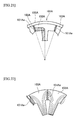
- Fig. 21 is a front main part view illustrating a state of a stator core attached to a core case by shrink-fitting.
- Fig. 22 is a front main part view illustrating the stator core.
- Fig. 23 is a front main part view illustrating a state of a stator core attached to a core case by shrink-fitting.
- Fig. 24 is a sectional view illustrating a state of a stator core attached to a core case by shrink-fitting.
- stator core segments 103A, 103B and 103C of stator cores 101A, 101B and 101C of motors are joined to form an annular shape and are received and fixed by shrink-fitting in core cases 105A, 105B and 105C.
- stator core 101A of Figs. 21 and 22 has slits 101Aa made therein so as not to generate compressive stress, and the stator cores 103B and 103C of Figs. 22 and 24 have holes 103Ba and 103Ca to reduce compressive stress.
- the slits 101Aa and the holes 103Ba and 103Ca make an increase of magnetic resistance and result in a problem of deteriorating magnetic properties.
- the problem to be solved by the invention lies in that a reduction in compressive stress by means of slits or holes causes an increase in magnetic resistance and deteriorates magnetic properties.
- the present invention in order to reduce compressive stress at a portion having a high density of magnetic flux without forming slits or holes, characterizes a stator core for a motor in that the stator core including an annular yoke and teeth protruding radially inward from an inner periphery of the yoke, an outer periphery of the yoke attached to an inner periphery of an annular member with a radially inwardly tightening interference, comprises a circumferentially deformable part formed on a radially outer peripheral side of the yoke and compressively deformed in a circumferential direction by the tightening interference; circumferentially facing divided parts formed on a radially inner peripheral side of the yoke, and each having a dividing line that is oriented in a radial direction and reaches a portion between the teeth and divided surfaces that face each other without a gap; and radially facing divided parts formed between the radially inner and outer sides of the yok
- the present invention characterizes a stator core manufacturing method for manufacturing a stator core for a motor in that the stator core manufacturing method comprises a segment processing step of processing a plurality of circumferential stator core segments divided at the circumferentially pressed divided parts, the circumferentially facing divided parts, and the radially facing divided parts; and an assembly step of joining the plurality of stator core segments annularly in the circumferential direction and attaching the plurality of stator core segments to the inner periphery of the annular member with the radially inwardly tightening interference, thereby pressing the divided surfaces of the circumferentially pressed divided parts against each other and facing the divided surfaces of the circumferentially facing divided parts without a gap in the circumferential direction.
- the present invention characterizes a stator core manufacturing method for manufacturing the stator core for a motor in that the stator core manufacturing method comprises a semi-finished core processing step of forming a semi-finished stator core having the ring part, circumferentially facing divided part correspondents, and radially facing divided part correspondents; and an assembly step of attaching the semi-finished stator core to the inner periphery of the annular member with the radially inwardly tightening interference, thereby causing compressive deformation of the ring part and facing the divided surfaces of the circumferentially facing divided parts without a gap in the circumferential direction.
- the stator core for a motor of the present invention generates the compressive stress by the attachment to the annular member with the tightening interference in the circumferentially deformable part on the outer peripheral side of the yoke, and the circumferentially facing divided parts on the inner peripheral side of the yoke are put into the state of the compressive stress being smaller than the compressive stress acting on the circumferentially deformable part or being zero.
- the stator core manufacturing method of the present invention produces the plurality of stator core segments, annularly joins the plurality of stator core segments in the circumferential direction, and attaches them to the inner periphery of the annular member with the radially inwardly tightening interference, thereby generating the compressive stress based on the tightening interference in the circumferentially pressed divided parts so that the circumferentially facing divided parts are put into the state of the compressive stress being smaller than the compressive stress acting on the circumferentially pressed divided parts or being zero.
- the stator core manufacturing method of the present invention produces the semi-finished stator core and attaches it to the inner periphery of the annular member with the radially inwardly tightening interference, thereby generating the compressive stress based on the tightening interference in the ring part so that the circumferentially facing divided parts are put into the state of the compressive stress being smaller than the compressive stress acting on the circumferentially deformable part or being zero.
- stator core that is provided with a circumferentially deformable part, circumferentially facing divided parts, and radially facing divided parts.
- Fig. 1 is a front main part view illustrating a state of a stator core attached to a motor case by shrink-fitting
- Fig. 2 is a side view illustrating the stator core at circumferentially pressed divided parts
- Fig. 3 is a sectional view partly illustrating a stack of the stator cores.
- a stator core 1 is made of a magnetic steel plate and has an annular yoke 3 and teeth 5 protruding radially inward from an inner periphery of the yoke 3.
- a plurality of stator cores 1 are stacked one on another, and an outer periphery of each yoke 3 in the stacked state is attached to an inner periphery of a motor case 7 as an annular member by shrink-fitting with a radial inward tightening interference.
- the yoke 3 is provided with circumferentially pressed divided parts 9, circumferentially facing divided parts 11, and radially facing divided parts 13.
- the circumferentially pressed divided parts 9 are formed in a circumferentially deformable part 14 on a radially outer peripheral side and each have dividing line 9a that is oriented in a radial direction of the stator core 1 so as to pass through the center of curvature (center of rotation) of the yoke 3.
- the circumferentially deformable part 14 is formed on the radially outer peripheral side of the yoke 3 and includes the outermost periphery of the yoke, and the circumferentially deformable part is annularly formed with a radial width of the circumferentially pressed divided parts 9 in a circumferential direction.
- the circumferentially deformable part 14 compressively deforms in the circumferential direction by the shrink-fitting of the stator core 1 into the inner peripheral side of the motor case 7 as will be described later.
- the dividing line 9a is oriented in the radial direction through a tooth 5.
- an extension line of the dividing line 9a is set so as to pass through a center of the tooth 5 in a width direction thereof and a center of the stator core 1.
- the circumferentially pressed divided part 9 has divided surfaces pressed against each other in the circumferential direction by the tightening interference and includes the outermost periphery of the yoke 3.
- the circumferentially facing divided parts 11 are provided on a radially inner peripheral side of the yoke 3 and each have a dividing line 11a that reaches a portion between teeth 5 and is oriented in the radial direction of the stator core 1. Accordingly, the dividing line 11a is oriented in the radial direction through the portion between the teeth 5. According to the present embodiment, an extension line of the dividing line 11a is set so as to pass through a center between the teeth 5 and the center of the stator core 1.
- the circumferentially facing divided parts 11 each have divided surfaces facing each other without a gap between them in the circumferential direction and the circumferentially facing divided parts 11 are shifted relative to the circumferentially pressed divided parts 9 in the circumferential direction.
- the radially facing divided parts 13 are formed at a center between the radially inner and outer sides of the yoke 3 along the circumferential direction at a predetermined interval, and each have a dividing line 13a that is oriented in the circumferential direction.
- the dividing line 13a is formed in an arc shape with a center of curvature that is the center of the stator core 1.
- the radially facing divided parts 13 are continuous at one ends with the respective circumferentially facing divided parts 11 and at the other ends with the respective circumferentially pressed divided parts 9.
- the radially facing divided part 13 connects between the circumferentially pressed divided part 9 and the circumferentially facing divided part 11 in the circumferential direction and has divided surfaces facing each other in the radial direction.
- the radially facing divided parts 13 may be formed with a radial gap between divided surfaces and, in this case, the divided surfaces may be also formed to be straight.
- Radial lengths of the circumferentially pressed divided parts 9 and the circumferentially facing divided parts 11 are the same in the present embodiment.
- a compressive stress acting on the circumferentially facing divided part 11 is smaller than a compressive stress on the circumferentially pressed divided part 9, or is zero. According to the present embodiment, the compressive stress acting on the circumferentially facing divided parts.
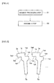
- Fig. 4 is a process chart illustrating a stator core manufacturing method.
- Fig. 5 is a front main part view illustrating stator core segments processed in a segment processing step
- Fig. 6 is a front main part view illustrating the stator core segments in a joined state before shrink-fitting in an assembly step.
- the stator core manufacturing method comprises a segment processing step S 1 and an assembly step S2, for manufacturing the stator core 1 for a motor.
- the segment processing step S1 forms a plurality of stator core segments 1a... in the circumferential direction that are divided as illustrated in Fig. 5 with the circumferentially pressed divided parts 9, the circumferentially facing divided parts 11, and the radially facing divided parts 13 in Fig. 1 .
- the stator core segments 1a... each have a yoke correspondent 3aa and a tooth correspondent 5a, and divided surfaces 1aa, 1ab, 1ac, 1ad, 1ae, and 1af.
- the divided surfaces 1ab and 1ae are formed in an arc shape in accordance with the dividing line 13a.
- the plurality of stator core segments 1a... are annularly joined together in the circumferential direction.
- the divided surfaces 1aa and 1ad are in contact with each other in the circumferential direction and the divided surfaces 1ab and 1ae are in contact with each other in the radial direction, to form a gap G between the divided surfaces 1ac and 1af as illustrated in Fig. 6 .
- the gap G is approximately 50 ⁇ m according to the present embodiment.
- the gap G is sufficient to allow a stress acting on the circumferentially facing divided part 11 to be put into a state of the compressive stress being smaller than the compressive stress acting on the circumferentially pressed divided part 9 or being zero due to the tightening interference.
- the divided surfaces of the respective circumferentially pressed divided parts 9 are pressed against each other by the tightening interference.
- a circumferential distortion caused by the pressing is absorbed by moving the divided surfaces 1ab and 1ae of the respective radially facing divided parts 13 relative to each other in the circumferential direction so that the divided surfaces 1 ac and 1af of the respective circumferentially facing divided parts 11 face each other in the circumferential direction without a gap as illustrated in Fig. 1 .
- the compressive stress is generated in the circumferentially pressed divided parts 9, and the compressive stress on an inner diameter side relative to the radially facing divided parts 13 is zero.
- the stator core 1 for the motor includes an annular yoke 3 and teeth 5 protruding radially inward from the inner periphery of the yoke 3 and the outer periphery of the yoke 3 is attached to the inner periphery of the motor case 7 by shrink-fitting with the radially inwardly tightening interference.
- the stator core 1 comprises the circumferentially deformable part 14 that is formed on the radially outer peripheral side of the yoke 3 and has the circumferentially pressed divided parts 9 each having the dividing surfaces 1aa and 1ad pressed against each other in the circumferential direction by the tightening interference; the circumferentially facing divided parts 11 formed on the radially inner peripheral side of the yoke 3, each having the dividing line 11a that is oriented in the radial direction and reaches the portion between teeth 5, and having the divided surfaces 1ac and 1af that face each other without a gap; and the radially facing divided parts 13 formed at the center or at a portion closer to the outer periphery or elsewhere between the radially inner and outer sides of the yoke 3 along the circumferential direction at the predetermined interval, and each having the divided surfaces 1ab and 1ae that face each other in the radial direction, and being continuous at one ends with the respective circumferentially facing divided parts 11 and at the other ends with the respective
- the circumferentially pressed divided parts 9 includes the outermost periphery of the yoke 3.
- the circumferentially pressed divided parts 9 can be provided on the an outermost peripheral side, thereby allowing the circumferentially facing divided parts 11 to be formed surely on the inner peripheral side.
- the dividing lines 9a and 11a are oriented to the center of the curvature of the yoke 3.
- the divided surfaces of the circumferentially pressed divided parts 9 are securely pressed by the tightening interference of the shrink-fitting, the divided surfaces of the radially facing divided parts 13 easily face each other without a gap, and the circumferentially facing divided parts 11 are securely formed with less magnetic resistance and less iron loss.
- the radial lengths of the circumferentially pressed divided parts 9 and the circumferentially facing divided parts 11 are the same.
- the dividing lines 9a of the circumferentially pressed divided parts 9 are oriented in the radial direction through the respective teeth 5 and the dividing lines 11a of the circumferentially facing divided parts 11 are oriented in the radial direction through the respective portions between the teeth 5.
- the circumferentially pressed divided parts 9 can be formed without dividing the teeth 5.
- the stator core manufacturing method includes the segment processing step S1 of forming the plurality of stator core segments 1a... in the circumferential direction divided at the circumferentially pressed divided parts 9, the circumferentially facing divided parts 11, and the radially facing divided parts 13; and the assembly step S2 of joining the plurality of stator core segments 1a... annularly in the circumferential direction and attaching the plurality of stator core segments to the inner periphery of the motor case 7 with the radially inwardly tightening interference, thereby pressing the divided surfaces 1aa and 1ad of the respective circumferentially pressed divided parts 9 against each other and facing the divided surfaces 1ac and 1af of the respective circumferentially facing divided parts 11 without a gap between them.
- the stator core 1 that is provided with the circumferentially pressed divided parts 9, the circumferentially facing divided parts 11, and the radially facing divided parts 13 is securely formed.
- Fig. 7 is a front main part view illustrating a stator core according to a modification.
- a stator core 1A radial lengths of circumferentially pressed divided parts 9A are formed relatively short, and radial lengths of circumferentially facing divided parts 11A are formed relatively long.
- the radial lengths of the circumferentially facing divided parts 11 A that involve compressive stress being smaller than compressive stress acting on the circumferentially pressed divided parts 9A or being zero are enlarged.
- the circumferentially deformable part 14A has an increased deformability due to a reduced width in a radial direction, and further reduces magnetic resistance, prevents the increase in iron loss.
- Figs. 8 to 10 are drawings according to a second embodiment of the present invention, in which Fig. 8 is a front main part view illustrating a stator core, Fig. 9 is a side view illustrating a flexible portion of the stator core, and Fig. 10 is a sectional view partly illustrating a stack of the stator cores.
- the basic structure according to the present embodiment is the same as that of the first embodiment, and the same parts will be represented with the same numerals and corresponding parts will be represented with the same numerals with "B" to omit duplicate description.
- the stator core 1B is provided with flexible portions 15 adjoining respective circumferentially pressed divided parts 9B in a circumferentially deformable part 14B for securing an amount of deformation in a circumferential direction.
- the flexible portions 15 have a convex-concave portion in a thickness direction of a yoke 3B.
- the convex-concave portions of the flexible portions 15 have a triangular chevron shape in the thickness direction in a cross section.
- the sectional shape of each flexible portion 15 is formed so that, when the stator cores 1 B are stacked, the flexible portions are closely stacked one on another, or, when producing the stack, the flexible portions are closely stacked under pressure.
- a yoke 3Ba of the stator core 1Ba at an end has a cutout 17 formed to escape an adjacent flexible portion 15.
- the present embodiment also provides the same effects as the first embodiment due to the presence of the circumferentially pressed divided parts 9B, the circumferentially facing divided parts 11B, and the radially facing divided parts 13B. Furthermore, in the present embodiment, since the amount of compression of the circumferentially pressed divided parts 9B due to the shrink-fitting is increased by the flexible portions 15, gaps formed in the circumferentially facing divided parts 11B before the shrink-fitting is set to, for example, approximately 70 ⁇ m to facilitate the setting of the gaps.
- Fig. 11 is a side view illustrating a flexible portion of a stator core according to a modification
- Fig. 12 is a sectional view partly illustrating a stack of the stator cores of according to the modification.
- the basic structure of the modification is the same as that of the example in Figs. 8 to 10 , and the same parts will be represented with the same numerals and corresponding components will be represented with the same characters with "C" omit duplicate description.
- a convex-concave portion of a flexible portion 15C provided in a circumferentially deformable part 14C has a triangular chevron shape in a thickness direction in a cross section so that the convex-concave portion protrudes both forward and rearward in a direction along an axis of the stator core 1C.
- the yokes 3Ca and 3Cb of stator cores 1Ca and 1Cb at both ends have cutouts 17Ca and 17Cb formed in a shape to escape adjacent flexible portions 15C.
- the amount of deformation of the flexible portions 15C is further increased relative to the example in Figs. 8 to 10 , thereby further easily setting gaps in the circumferentially facing divided parts (corresponding to the circumferentially facing divided parts 11B of Fig. 8 ).
- Fig. 13 is a side view illustrating a flexible portion of a stator core according to another modification
- Fig. 14 is a sectional view partly illustrating a stack of the stator cores according to the modification.
- the basic structure of the modification is the same as that of the example in Figs. 8 to 10 , and the same parts will be represented with the same characters and corresponding parts will be represented with the same numerals with "D" to omit duplicate description.
- a convex-concave portion of a flexible portion 15D provided in a circumferentially deformable part 14D has a curved chevron shape in a thickness direction in a cross section.
- a yoke 3Da of the stator core 1Da at an end has a cutout 17D formed in a shape to escape an adjacent flexible portion 15D.
- the modification provides substantially the same effects as the example of Figs. 8 to 10 .
- Fig. 15 is a side view illustrating a flexible portion of a stator core according to still another modification
- Fig. 16 is a sectional view partly illustrating a stack of the stator cores according to the modification.
- a convex-concave portion of a flexible portion 15E provided in a circumferentially deformable part 14E has a curved chevron shape in a thickness direction in a cross section so that the convex-concave portion protrudes both forward and rearward in a direction along an axis of the stator core 1E.
- the yokes 3Ea and 3Eb of stator cores 1Ea and 1Eb at both ends have cutouts 17Ea and 17Eb formed in a shape to escape adjacent flexible portions 15E.
- the modification provides substantially the same effects as the modification of Figs. 11 and 12 .
- Figs. 17 to 19 are drawings according to a third embodiment of the present invention in which Fig. 17 is a front main part view illustrating a state of a stator core attached to a motor case by shrink-fitting, Fig. 18 is a process chart illustrating a stator core manufacturing method, and Fig. 19 is a front main part view illustrating a state of a semi-finished stator core before the shrink-fitting.
- the basic structure of the present embodiment is the same as that of the first embodiment, and the same parts will be represented with the same numerals and corresponding components will be represented with the same numerals with "F" to omit duplicate description.
- a stator core 1F of the present third embodiment is provided with a circumferentially deformable part 14F having no circumferentially pressed divided parts and is a circumferentially continuous ring part.
- a radially facing divided parts 13F are continuous at one ends with respective circumferentially facing divided parts 11 and closed at the other ends.
- a stator core manufacturing method has a semi-finished core processing step S10 and an assembly step S 11, for producing a stator core 1 F for a motor.
- a semi-finished core 1Fa illustrated in Fig. 19 is formed.
- the semi-finished core 1Fa is provided with circumferentially facing divided part correspondents 11Fa, radially facing divided part correspondents 13Fa, a circumferentially deformable part correspondent 14Fa, and teeth correspondents 5a, and divided surfaces 1ab, 1ae, 1ac, and 1af.
- the circumferentially facing divided part correspondents 11Fa, the radially facing divided part correspondents 13a, the circumferentially deformable part correspondent 14Fa, and the teeth correspondents 5a correspond to the circumferentially facing divided parts 11, the radially facing divided parts 13F, the circumferentially deformable part 14F, and the teeth 5 in Fig. 17 .
- the semi-finished core 1Fa before shrink-fitting has a gap G between the divided surfaces 1ac and 1af.
- This gap G is approximately 50 ⁇ m in the present embodiment.
- the requirements for the gap G are as mentioned above.
- semi-finished cores 1Fa... of Fig. 19 are stacked one on another in a thickness direction and attached to an inner periphery of a motor case 7 of Fig. 17 by shrink-fitting with a radially inwardly tightening interference.
- the circumferentially deformable part correspondent 14Fa of Fig. 19 is compressed in a circumferential direction due to the tightening interference.
- a circumferential distortion caused by this compression is absorbed by moving the divided surfaces 1ab and 1ae of the respective radially facing divided part correspondents 13Fa relative to each other in the circumferential direction, thereby making the divided surfaces 1ac and 1af of the respective circumferentially facing divided parts 11 face each other without a gap as illustrated in Fig. 17 .
- the circumferentially facing divided parts 11 can be put into a state of compressive stress being smaller than compressive stress acting on the circumferentially deformable parts 9 or being zero, thereby providing the same effects as the first embodiment.
- the semi-finished core 1Fa is not divided, it is easy to handle and reduces the number of parts for easy assembly and easy parts control.
- the present embodiment may also form flexible portions on an outer peripheral side or elsewhere relative to the radially facing divided parts 13F, thereby facilitating the compressive deformation of the circumferentially deformable part 14F.
- the radial width of the circumferentially deformable part 14F may be relatively narrow and the radial length of the circumferentially facing divided parts 11 may be relatively long. In this case, the compressive deformation of the circumferentially deformable part 14F by the tightening interference can be made easier.
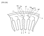
- Fig. 20 is a front main part view illustrating a state of a stator core according to a modification of the third embodiment attached to a motor case by shrink-fitting.
- dividing lines 13a of radially facing divided parts 13F are set to be inclined so that one ends of the dividing lines continuous to respective circumferentially facing divided parts 11 are located on an inner peripheral side relative to the other closed ends. Accordingly, when divided surfaces of the radially facing divided part 13F move relative to each other in a circumferential direction by compressive deformation at the time of shrink-fitting, the divided surfaces come in closely contact with each other.
Landscapes
- Engineering & Computer Science (AREA)
- Power Engineering (AREA)
- Manufacturing & Machinery (AREA)
- Iron Core Of Rotating Electric Machines (AREA)
- Manufacture Of Motors, Generators (AREA)
Abstract
It is capable of reducing compressive stress without forming slits or holes.
A stator core comprises a circumferentially deformable part 14 that is formed on a radially outer peripheral side of a yoke 3 and has circumferentially pressed divided parts 9 each having dividing surfaces 1aa and 1ad pressed against each other in a circumferential direction by tightening interference; circumferentially facing divided parts 11 formed on a radially inner peripheral side of the yoke 3, each having a dividing line 11 a that is oriented in a radial direction and reaches a portion between teeth 5 and divided surfaces 1ac and 1af that face each other without a gap; and radially facing divided parts 13 formed at the center or at a portion closer to the outer periphery or elsewhere between the radially inner and outer sides of the yoke 3 along the circumferential direction at the predetermined interval, and each having divided surfaces 1ab and 1ae that face each other in the radial direction, and being continuous at one ends with the respective circumferentially facing divided parts 11 and at the other ends with the respective circumferentially pressed divided parts 9, the divided surfaces 1ab and 1ae moved relative to each other in the circumferential direction by compressive deformation of the circumferentially deformable part 14. The circumferentially facing divided parts 11 are in a state of compressive stress being smaller than compressive stress acting on the circumferentially pressed divided parts 9 or being zero.
Description
- The present invention relates to a stator core for a motor and its manufacturing method.
- Conventionally, there are ones disclosed in
Patent Documents Figs. 21 to 24 .Fig. 21 is a front main part view illustrating a state of a stator core attached to a core case by shrink-fitting.Fig. 22 is a front main part view illustrating the stator core.Fig. 23 is a front main part view illustrating a state of a stator core attached to a core case by shrink-fitting.Fig. 24 is a sectional view illustrating a state of a stator core attached to a core case by shrink-fitting. - In all
Figs. 21 to 24 ,stator core segments stator cores core cases - Where, there is a problem that iron loss increases due to compressive stress generated in the
stator core segments - To address this, the
stator core 101A ofFigs. 21 and 22 has slits 101Aa made therein so as not to generate compressive stress, and thestator cores Figs. 22 and24 have holes 103Ba and 103Ca to reduce compressive stress. - However, the slits 101Aa and the holes 103Ba and 103Ca make an increase of magnetic resistance and result in a problem of deteriorating magnetic properties.
- On the other hand, in the case of the slits 101Aa, it is conceivable to compressively deform contacting portions on the outer peripheral side toward a direction to eliminate the slits (circumferential direction) by the compressive stress.
- However, only the deformation amount due to the distortion around the contacting portions on the outer peripheral side results in the small amount of the compressive deformation of the contacting portions, and it is physically difficult to eliminate the slit 101Aa.
- Such a problem also exists in stator cores other than a divided- type stator core.
-
- Patent Document 1:
JP 2005-51941 A - Patent Document 2:
JP 2009-261162 A - Patent Document 3:
JP 2002-136013 A - The problem to be solved by the invention lies in that a reduction in compressive stress by means of slits or holes causes an increase in magnetic resistance and deteriorates magnetic properties.
- The present invention, in order to reduce compressive stress at a portion having a high density of magnetic flux without forming slits or holes, characterizes a stator core for a motor in that the stator core including an annular yoke and teeth protruding radially inward from an inner periphery of the yoke, an outer periphery of the yoke attached to an inner periphery of an annular member with a radially inwardly tightening interference, comprises a circumferentially deformable part formed on a radially outer peripheral side of the yoke and compressively deformed in a circumferential direction by the tightening interference; circumferentially facing divided parts formed on a radially inner peripheral side of the yoke, and each having a dividing line that is oriented in a radial direction and reaches a portion between the teeth and divided surfaces that face each other without a gap; and radially facing divided parts formed between the radially inner and outer sides of the yoke along the circumferential direction at a predetermined interval, each having divided surfaces that face each other in the radial direction, and being continuous at one ends with the respective circumferentially facing divided parts, the divided surfaces moved relative to each other in the circumferential direction by compressive deformation of the circumferentially deformable part, wherein the circumferentially facing divided parts are in a state of a compressive stress being smaller than a compressive stress acting on the circumferentially deformable part or being zero.
- The present invention characterizes a stator core manufacturing method for manufacturing a stator core for a motor in that the stator core manufacturing method comprises a segment processing step of processing a plurality of circumferential stator core segments divided at the circumferentially pressed divided parts, the circumferentially facing divided parts, and the radially facing divided parts; and an assembly step of joining the plurality of stator core segments annularly in the circumferential direction and attaching the plurality of stator core segments to the inner periphery of the annular member with the radially inwardly tightening interference, thereby pressing the divided surfaces of the circumferentially pressed divided parts against each other and facing the divided surfaces of the circumferentially facing divided parts without a gap in the circumferential direction.
- The present invention characterizes a stator core manufacturing method for manufacturing the stator core for a motor in that the stator core manufacturing method comprises a semi-finished core processing step of forming a semi-finished stator core having the ring part, circumferentially facing divided part correspondents, and radially facing divided part correspondents; and an assembly step of attaching the semi-finished stator core to the inner periphery of the annular member with the radially inwardly tightening interference, thereby causing compressive deformation of the ring part and facing the divided surfaces of the circumferentially facing divided parts without a gap in the circumferential direction.
- Because of the above configuration, the stator core for a motor of the present invention generates the compressive stress by the attachment to the annular member with the tightening interference in the circumferentially deformable part on the outer peripheral side of the yoke, and the circumferentially facing divided parts on the inner peripheral side of the yoke are put into the state of the compressive stress being smaller than the compressive stress acting on the circumferentially deformable part or being zero.
- As a result, much of magnetic flux passes through the circumferentially facing divided parts involving less compressive stress, to realize small magnetic loss such as iron loss and the stable attachment to the annular member.
- Because of the above configuration, the stator core manufacturing method of the present invention produces the plurality of stator core segments, annularly joins the plurality of stator core segments in the circumferential direction, and attaches them to the inner periphery of the annular member with the radially inwardly tightening interference, thereby generating the compressive stress based on the tightening interference in the circumferentially pressed divided parts so that the circumferentially facing divided parts are put into the state of the compressive stress being smaller than the compressive stress acting on the circumferentially pressed divided parts or being zero.
- Because of the above configuration, the stator core manufacturing method of the present invention produces the semi-finished stator core and attaches it to the inner periphery of the annular member with the radially inwardly tightening interference, thereby generating the compressive stress based on the tightening interference in the ring part so that the circumferentially facing divided parts are put into the state of the compressive stress being smaller than the compressive stress acting on the circumferentially deformable part or being zero.
-
- [
Fig. 1 ] It is a front main part view illustrating a state of a stator core attached to a motor case by shrink-fitting. (First embodiment) - [
Fig. 2 ] It is a side view illustrating the stator core at circumferentially pressed divided parts. (First embodiment) - [
Fig. 3 ] It is a sectional view illustrating a stack of the stator cores. (First embodiment) - [
Fig. 4 ] It is a process chart illustrating a stator core manufacturing method. (First embodiment) - [
Fig. 5 ] It is a front main part view illustrating stator core segments processed in a segment processing step. (First embodiment) - [
Fig. 6 ] It is a front main part view illustrating the stator core segments in a joined state before shrink-fitting in an assembly step. (First embodiment) - [
Fig. 7 ] It is a front main part view illustrating a stator core according to a modification. (First embodiment) - [
Fig. 8 ] It is a front main part view illustrating a stator core. (Second embodiment) - [
Fig. 9 ] It is a side view illustrating a flexible portion of the stator core. (Second embodiment) - [
Fig. 10 ] It is a sectional view partly illustrating a stack of the stator cores. (Second embodiment) - [
Fig. 11 ] It is a side view illustrating a flexible portion of a stator core according to a modification. (Second embodiment) - [
Fig. 12 ] It is a sectional view partly illustrating a stack of the stator cores according to the modification. (Second embodiment) - [
Fig. 13 ] It is a side view illustrating a flexible portion of a stator core according to another modification. (Second embodiment) - [
Fig. 14 ] It is a sectional view partly illustrating a stack of the stator cores according to the modification. (Second embodiment) - [
Fig. 15 ] It is a side view illustrating a flexible portion of a stator core according to still another modification. (Second embodiment) - [
Fig. 16 ] It is a sectional view partly illustrating a stack of the stator cores according to the modification. (Second embodiment) - [
Fig. 17 ] It is a front main part view illustrating a state of a stator core attached to a motor case by shrink-fitting. (Third embodiment) - [
Fig. 18 ] It is a process chart illustrating a stator core manufacturing method. (Third embodiment) - [
Fig. 19 ] It is a front main part view illustrating a state of a semi-finished stator core before shrink-fitting. (Third embodiment) - [
Fig. 20 ] It is a front main part view illustrating a state of a stator core according to a modification attached to a motor case by shrink-fitting. (Third embodiment) - [
Fig. 21 ] It is a front main part view illustrating a state of a stator core attached to a core case by shrink-fitting. (Prior art) - [
Fig. 22 ] It is a front main part view illustrating the stator core. (Prior art) - [
Fig. 23 ] It is a front main part view illustrating a state of a stator core attached to a core case by shrink-fitting. (Prior art) - [
Fig. 24 ] It is a sectional view illustrating a state of a stator core attached to a core case by shrink-fitting. (Prior art) - The object capable of reducing compressive stress without forming slits or holes is accomplished by a stator core that is provided with a circumferentially deformable part, circumferentially facing divided parts, and radially facing divided parts.
-
Fig. 1 is a front main part view illustrating a state of a stator core attached to a motor case by shrink-fitting,Fig. 2 is a side view illustrating the stator core at circumferentially pressed divided parts, andFig. 3 is a sectional view partly illustrating a stack of the stator cores. - As illustrated in
Figs. 1 to 3 , astator core 1 is made of a magnetic steel plate and has anannular yoke 3 andteeth 5 protruding radially inward from an inner periphery of theyoke 3. A plurality ofstator cores 1 are stacked one on another, and an outer periphery of eachyoke 3 in the stacked state is attached to an inner periphery of amotor case 7 as an annular member by shrink-fitting with a radial inward tightening interference. - The
yoke 3 is provided with circumferentially pressed dividedparts 9, circumferentially facing dividedparts 11, and radially facing dividedparts 13. - The circumferentially pressed divided
parts 9 are formed in a circumferentiallydeformable part 14 on a radially outer peripheral side and each have dividingline 9a that is oriented in a radial direction of thestator core 1 so as to pass through the center of curvature (center of rotation) of theyoke 3. - The circumferentially
deformable part 14 is formed on the radially outer peripheral side of theyoke 3 and includes the outermost periphery of the yoke, and the circumferentially deformable part is annularly formed with a radial width of the circumferentially pressed dividedparts 9 in a circumferential direction. The circumferentiallydeformable part 14 compressively deforms in the circumferential direction by the shrink-fitting of thestator core 1 into the inner peripheral side of themotor case 7 as will be described later. - The
dividing line 9a is oriented in the radial direction through atooth 5. In the present embodiment, an extension line of thedividing line 9a is set so as to pass through a center of thetooth 5 in a width direction thereof and a center of thestator core 1. The circumferentially pressed dividedpart 9 has divided surfaces pressed against each other in the circumferential direction by the tightening interference and includes the outermost periphery of theyoke 3. - The circumferentially facing divided
parts 11 are provided on a radially inner peripheral side of theyoke 3 and each have adividing line 11a that reaches a portion betweenteeth 5 and is oriented in the radial direction of thestator core 1. Accordingly, thedividing line 11a is oriented in the radial direction through the portion between theteeth 5. According to the present embodiment, an extension line of thedividing line 11a is set so as to pass through a center between theteeth 5 and the center of thestator core 1. The circumferentially facing dividedparts 11 each have divided surfaces facing each other without a gap between them in the circumferential direction and the circumferentially facing dividedparts 11 are shifted relative to the circumferentially pressed dividedparts 9 in the circumferential direction. - The radially facing divided
parts 13 are formed at a center between the radially inner and outer sides of theyoke 3 along the circumferential direction at a predetermined interval, and each have adividing line 13a that is oriented in the circumferential direction. According to the present embodiment, thedividing line 13a is formed in an arc shape with a center of curvature that is the center of thestator core 1. The radially facing dividedparts 13 are continuous at one ends with the respective circumferentially facing dividedparts 11 and at the other ends with the respective circumferentially pressed dividedparts 9. - Accordingly, the radially facing divided
part 13 connects between the circumferentially pressed dividedpart 9 and the circumferentially facing dividedpart 11 in the circumferential direction and has divided surfaces facing each other in the radial direction. - The radially facing divided
parts 13 may be formed with a radial gap between divided surfaces and, in this case, the divided surfaces may be also formed to be straight. - Radial lengths of the circumferentially pressed divided
parts 9 and the circumferentially facing dividedparts 11 are the same in the present embodiment. A compressive stress acting on the circumferentially facing dividedpart 11 is smaller than a compressive stress on the circumferentially pressed dividedpart 9, or is zero. According to the present embodiment, the compressive stress acting on the circumferentially facing divided parts. -
Fig. 4 is a process chart illustrating a stator core manufacturing method.Fig. 5 is a front main part view illustrating stator core segments processed in a segment processing step, andFig. 6 is a front main part view illustrating the stator core segments in a joined state before shrink-fitting in an assembly step. - As illustrated in
Fig. 4 , the stator core manufacturing method according to the present embodiment comprises a segmentprocessing step S 1 and an assembly step S2, for manufacturing thestator core 1 for a motor. - The segment processing step S1 forms a plurality of
stator core segments 1a... in the circumferential direction that are divided as illustrated inFig. 5 with the circumferentially pressed dividedparts 9, the circumferentially facing dividedparts 11, and the radially facing dividedparts 13 inFig. 1 . Thestator core segments 1a... each have a yoke correspondent 3aa and atooth correspondent 5a, and divided surfaces 1aa, 1ab, 1ac, 1ad, 1ae, and 1af. The divided surfaces 1ab and 1ae are formed in an arc shape in accordance with thedividing line 13a. - In the assembly step S2, the plurality of
stator core segments 1a... are annularly joined together in the circumferential direction. In this joined state before the shrink-fitting, the divided surfaces 1aa and 1ad are in contact with each other in the circumferential direction and the divided surfaces 1ab and 1ae are in contact with each other in the radial direction, to form a gap G between the divided surfaces 1ac and 1af as illustrated inFig. 6 . The gap G is approximately 50µm according to the present embodiment. The gap G, however, is sufficient to allow a stress acting on the circumferentially facing dividedpart 11 to be put into a state of the compressive stress being smaller than the compressive stress acting on the circumferentially pressed dividedpart 9 or being zero due to the tightening interference. - Thereafter, a plurality of sets of the annularly joined
stator core segments 1a... are stacked one on another in a thickness direction thereof and attached to the inner periphery of themotor case 7 by shrink-fitting with the radially inwardly tightening interference. - After completion of this attachment by shrink-fitting, the divided surfaces of the respective circumferentially pressed divided
parts 9 are pressed against each other by the tightening interference. A circumferential distortion caused by the pressing is absorbed by moving the divided surfaces 1ab and 1ae of the respective radially facing dividedparts 13 relative to each other in the circumferential direction so that the dividedsurfaces 1 ac and 1af of the respective circumferentially facing dividedparts 11 face each other in the circumferential direction without a gap as illustrated inFig. 1 . - In the
stator core 1 according to the present embodiment, the compressive stress is generated in the circumferentially pressed dividedparts 9, and the compressive stress on an inner diameter side relative to the radially facing dividedparts 13 is zero. - As a result, there is no increase in iron loss on the inner diameter side relative to the radially facing divided
parts 13, and magnetic flux passes efficiently from theteeth 5 through the circumferentially facing dividedparts 11. - According to the first embodiment of the present invention, the
stator core 1 for the motor includes anannular yoke 3 andteeth 5 protruding radially inward from the inner periphery of theyoke 3 and the outer periphery of theyoke 3 is attached to the inner periphery of themotor case 7 by shrink-fitting with the radially inwardly tightening interference. Thestator core 1 comprises the circumferentiallydeformable part 14 that is formed on the radially outer peripheral side of theyoke 3 and has the circumferentially pressed dividedparts 9 each having the dividing surfaces 1aa and 1ad pressed against each other in the circumferential direction by the tightening interference; the circumferentially facing dividedparts 11 formed on the radially inner peripheral side of theyoke 3, each having thedividing line 11a that is oriented in the radial direction and reaches the portion betweenteeth 5, and having the divided surfaces 1ac and 1af that face each other without a gap; and the radially facing dividedparts 13 formed at the center or at a portion closer to the outer periphery or elsewhere between the radially inner and outer sides of theyoke 3 along the circumferential direction at the predetermined interval, and each having the divided surfaces 1ab and 1ae that face each other in the radial direction, and being continuous at one ends with the respective circumferentially facing dividedparts 11 and at the other ends with the respective circumferentially pressed dividedparts 9, the divided surfaces 1ab and 1ae moved relative to each other in the circumferential direction by the compressive deformation of the circumferentiallydeformable part 14. The circumferentially facing dividedparts 11 are in a state of the compressive stress being smaller than the compressive stress acting on the circumferentially pressed dividedparts 9 or being zero. - As a result, the magnetic flux is efficiently passed from the
teeth 5 through the circumferentially facing dividedparts 11 as mentioned above, thereby enhancing the output efficiency of the motor. - In the case of the above-described conventional one of a slit type, it is physically difficult to eliminate the slits. In the present embodiment, even if dimensions are relatively rough by setting the circumferentially pressed divided
parts 9 and the circumferentially facing dividedparts 11 in a stepped shape, the divided surfaces of the respective circumferentially facing dividedparts 11 easily face each other without a gap in zero compressive stress due to the circumferential distortion from the circumferentially pressed dividedparts 9 to the circumferentially facing dividedparts 11. This securely improves the output efficiency of the motor. - The circumferentially pressed divided
parts 9 includes the outermost periphery of theyoke 3. - Accordingly, the circumferentially pressed divided
parts 9 can be provided on the an outermost peripheral side, thereby allowing the circumferentially facing dividedparts 11 to be formed surely on the inner peripheral side. - The
dividing lines yoke 3. - Accordingly, the divided surfaces of the circumferentially pressed divided
parts 9 are securely pressed by the tightening interference of the shrink-fitting, the divided surfaces of the radially facing dividedparts 13 easily face each other without a gap, and the circumferentially facing dividedparts 11 are securely formed with less magnetic resistance and less iron loss. - The radial lengths of the circumferentially pressed divided
parts 9 and the circumferentially facing dividedparts 11 are the same. - As a result, compressive force by the shrink-fitting is received by the pressed divided surfaces of the circumferentially pressed divided
parts 9, thereby making the divided surfaces of the radially facing dividedparts 13 face each other without a gap. - The
dividing lines 9a of the circumferentially pressed dividedparts 9 are oriented in the radial direction through therespective teeth 5 and thedividing lines 11a of the circumferentially facing dividedparts 11 are oriented in the radial direction through the respective portions between theteeth 5. - As a result, the circumferentially pressed divided
parts 9 can be formed without dividing theteeth 5. - The stator core manufacturing method includes the segment processing step S1 of forming the plurality of
stator core segments 1a... in the circumferential direction divided at the circumferentially pressed dividedparts 9, the circumferentially facing dividedparts 11, and the radially facing dividedparts 13; and the assembly step S2 of joining the plurality ofstator core segments 1a... annularly in the circumferential direction and attaching the plurality of stator core segments to the inner periphery of themotor case 7 with the radially inwardly tightening interference, thereby pressing the divided surfaces 1aa and 1ad of the respective circumferentially pressed dividedparts 9 against each other and facing the divided surfaces 1ac and 1af of the respective circumferentially facing dividedparts 11 without a gap between them. - Accordingly, through the segment processing step S1 and the assembly step S2, the
stator core 1 that is provided with the circumferentially pressed dividedparts 9, the circumferentially facing dividedparts 11, and the radially facing dividedparts 13 is securely formed. -
Fig. 7 is a front main part view illustrating a stator core according to a modification. In a stator core 1A, radial lengths of circumferentially pressed dividedparts 9A are formed relatively short, and radial lengths of circumferentially facing dividedparts 11A are formed relatively long. - Accordingly, the radial lengths of the circumferentially facing divided
parts 11 A that involve compressive stress being smaller than compressive stress acting on the circumferentially pressed dividedparts 9A or being zero are enlarged. The circumferentiallydeformable part 14A has an increased deformability due to a reduced width in a radial direction, and further reduces magnetic resistance, prevents the increase in iron loss. -
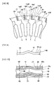
Figs. 8 to 10 are drawings according to a second embodiment of the present invention, in whichFig. 8 is a front main part view illustrating a stator core,Fig. 9 is a side view illustrating a flexible portion of the stator core, andFig. 10 is a sectional view partly illustrating a stack of the stator cores. The basic structure according to the present embodiment is the same as that of the first embodiment, and the same parts will be represented with the same numerals and corresponding parts will be represented with the same numerals with "B" to omit duplicate description. - The
stator core 1B according to the present embodiment, as illustrated inFigs. 8 to 10 , is provided withflexible portions 15 adjoining respective circumferentially pressed dividedparts 9B in a circumferentiallydeformable part 14B for securing an amount of deformation in a circumferential direction. Theflexible portions 15 have a convex-concave portion in a thickness direction of ayoke 3B. According to the present embodiment, the convex-concave portions of theflexible portions 15 have a triangular chevron shape in the thickness direction in a cross section. The sectional shape of eachflexible portion 15 is formed so that, when thestator cores 1 B are stacked, the flexible portions are closely stacked one on another, or, when producing the stack, the flexible portions are closely stacked under pressure. - As illustrated in
Fig. 10 , a yoke 3Ba of the stator core 1Ba at an end has acutout 17 formed to escape an adjacentflexible portion 15. - Accordingly, the present embodiment also provides the same effects as the first embodiment due to the presence of the circumferentially pressed divided
parts 9B, the circumferentially facing dividedparts 11B, and the radially facing dividedparts 13B. Furthermore, in the present embodiment, since the amount of compression of the circumferentially pressed dividedparts 9B due to the shrink-fitting is increased by theflexible portions 15, gaps formed in the circumferentially facing dividedparts 11B before the shrink-fitting is set to, for example, approximately 70µm to facilitate the setting of the gaps. -
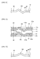
Fig. 11 is a side view illustrating a flexible portion of a stator core according to a modification, andFig. 12 is a sectional view partly illustrating a stack of the stator cores of according to the modification. The basic structure of the modification is the same as that of the example inFigs. 8 to 10 , and the same parts will be represented with the same numerals and corresponding components will be represented with the same characters with "C" omit duplicate description. - In a
stator core 1C ofFigs. 11 and 12 , a convex-concave portion of aflexible portion 15C provided in a circumferentiallydeformable part 14C has a triangular chevron shape in a thickness direction in a cross section so that the convex-concave portion protrudes both forward and rearward in a direction along an axis of thestator core 1C. The yokes 3Ca and 3Cb of stator cores 1Ca and 1Cb at both ends have cutouts 17Ca and 17Cb formed in a shape to escape adjacentflexible portions 15C. - With this modification, the amount of deformation of the
flexible portions 15C is further increased relative to the example inFigs. 8 to 10 , thereby further easily setting gaps in the circumferentially facing divided parts (corresponding to the circumferentially facing dividedparts 11B ofFig. 8 ). -
Fig. 13 is a side view illustrating a flexible portion of a stator core according to another modification andFig. 14 is a sectional view partly illustrating a stack of the stator cores according to the modification. The basic structure of the modification is the same as that of the example inFigs. 8 to 10 , and the same parts will be represented with the same characters and corresponding parts will be represented with the same numerals with "D" to omit duplicate description. - In a
stator core 1D ofFigs. 13 and14 , a convex-concave portion of aflexible portion 15D provided in a circumferentiallydeformable part 14D has a curved chevron shape in a thickness direction in a cross section. A yoke 3Da of the stator core 1Da at an end has acutout 17D formed in a shape to escape an adjacentflexible portion 15D. - Accordingly, the modification provides substantially the same effects as the example of
Figs. 8 to 10 . -
Fig. 15 is a side view illustrating a flexible portion of a stator core according to still another modification andFig. 16 is a sectional view partly illustrating a stack of the stator cores according to the modification. In astator core 1E ofFigs. 15 and 16 , a convex-concave portion of aflexible portion 15E provided in a circumferentiallydeformable part 14E has a curved chevron shape in a thickness direction in a cross section so that the convex-concave portion protrudes both forward and rearward in a direction along an axis of thestator core 1E. The yokes 3Ea and 3Eb of stator cores 1Ea and 1Eb at both ends have cutouts 17Ea and 17Eb formed in a shape to escape adjacentflexible portions 15E. The modification provides substantially the same effects as the modification ofFigs. 11 and 12 . -
Figs. 17 to 19 are drawings according to a third embodiment of the present invention in whichFig. 17 is a front main part view illustrating a state of a stator core attached to a motor case by shrink-fitting,Fig. 18 is a process chart illustrating a stator core manufacturing method, andFig. 19 is a front main part view illustrating a state of a semi-finished stator core before the shrink-fitting. The basic structure of the present embodiment is the same as that of the first embodiment, and the same parts will be represented with the same numerals and corresponding components will be represented with the same numerals with "F" to omit duplicate description. - As illustrated in
Fig. 17 , astator core 1F of the present third embodiment is provided with a circumferentiallydeformable part 14F having no circumferentially pressed divided parts and is a circumferentially continuous ring part. A radially facing dividedparts 13F are continuous at one ends with respective circumferentially facing dividedparts 11 and closed at the other ends. - As illustrated in
Fig. 18 , a stator core manufacturing method according to the present embodiment has a semi-finished core processing step S10 and anassembly step S 11, for producing astator core 1 F for a motor. - In the semi-finished core processing step S10, a semi-finished core 1Fa illustrated in
Fig. 19 is formed. The semi-finished core 1Fa is provided with circumferentially facing divided part correspondents 11Fa, radially facing divided part correspondents 13Fa, a circumferentially deformable part correspondent 14Fa, andteeth correspondents 5a, and divided surfaces 1ab, 1ae, 1ac, and 1af. - The circumferentially facing divided part correspondents 11Fa, the radially facing divided
part correspondents 13a, the circumferentially deformable part correspondent 14Fa, and theteeth correspondents 5a correspond to the circumferentially facing dividedparts 11, the radially facing dividedparts 13F, the circumferentiallydeformable part 14F, and theteeth 5 inFig. 17 . - As illustrated in
Fig. 19 , the semi-finished core 1Fa before shrink-fitting has a gap G between the divided surfaces 1ac and 1af. This gap G is approximately 50µm in the present embodiment. The requirements for the gap G are as mentioned above. - In the assembly step S11 of
Fig. 18 , semi-finished cores 1Fa... ofFig. 19 are stacked one on another in a thickness direction and attached to an inner periphery of amotor case 7 ofFig. 17 by shrink-fitting with a radially inwardly tightening interference. - After completion of this attachment by the shrink-fitting, the circumferentially deformable part correspondent 14Fa of
Fig. 19 is compressed in a circumferential direction due to the tightening interference. A circumferential distortion caused by this compression is absorbed by moving the divided surfaces 1ab and 1ae of the respective radially facing divided part correspondents 13Fa relative to each other in the circumferential direction, thereby making the divided surfaces 1ac and 1af of the respective circumferentially facing dividedparts 11 face each other without a gap as illustrated inFig. 17 . - Accordingly, in the present embodiment, the circumferentially facing divided
parts 11 can be put into a state of compressive stress being smaller than compressive stress acting on the circumferentiallydeformable parts 9 or being zero, thereby providing the same effects as the first embodiment. - Furthermore, since the semi-finished core 1Fa is not divided, it is easy to handle and reduces the number of parts for easy assembly and easy parts control.
- Incidentally, the present embodiment may also form flexible portions on an outer peripheral side or elsewhere relative to the radially facing divided
parts 13F, thereby facilitating the compressive deformation of the circumferentiallydeformable part 14F. - The radial width of the circumferentially
deformable part 14F may be relatively narrow and the radial length of the circumferentially facing dividedparts 11 may be relatively long. In this case, the compressive deformation of the circumferentiallydeformable part 14F by the tightening interference can be made easier. -
Fig. 20 is a front main part view illustrating a state of a stator core according to a modification of the third embodiment attached to a motor case by shrink-fitting. - In this modification, dividing
lines 13a of radially facing dividedparts 13F are set to be inclined so that one ends of the dividing lines continuous to respective circumferentially facing dividedparts 11 are located on an inner peripheral side relative to the other closed ends. Accordingly, when divided surfaces of the radially facing dividedpart 13F move relative to each other in a circumferential direction by compressive deformation at the time of shrink-fitting, the divided surfaces come in closely contact with each other. - Even if the divided surfaces of the radially facing divided
part 13F do not come in closely contact with each other by the compressive deformation at the time of the shrink-fitting, the gap between the divided surfaces can be minimized to improve magnetic properties. - Incidentally, such setting of the
dividing line 13a is also equally applicable to thestator cores -
- 1, 1B, 1C, 1D, 1E, 1F stator core
- 1Fa semi-finished core
- 1a... stator core segments
- 1aa, 1ab, 1ac, 1ad, 1ae, 1af divided surface
- 3, 3A, 3B, 3C, 3D, 3E yoke
- 5 tooth
- 5a tooth correspondent
- 7 motor case (annular member)
- 9, 9A, 9B, 9C, 9D, 9E circumferentially pressed divided part
- 9a, 11a, 13a dividing line
- 11 circumferentially facing divided part
- 11F circumferentially facing divided part correspondent
- 13, 13F radially facing divided part
- 13F radially facing divided part correspondent
- 14, 14A, 14B, 14C, 14D, 14E, 14F circumferentially deformable part
- 14Fa circumferentially deformable part correspondent
- 15, 15C, 15D, 15E flexible portion
-
S 1 segment processing step - S2, S11 assembly step
- S10 semi-finished core processsing step
Claims (14)
- A stator core for a motor including an annular yoke and teeth protruding radially inward from an inner periphery of the yoke, an outer periphery of the yoke attached to an inner periphery of an annular member with a radially inwardly tightening interference, comprising:a circumferentially deformable part formed on a radially outer peripheral side of the yoke and compressively deformed in a circumferential direction by the tightening interference;circumferentially facing divided parts formed on a radially inner peripheral side of the yoke, and each having a dividing line that is oriented in a radial direction and reaches a portion between the teeth and divided surfaces that face each other without a gap; andradially facing divided parts formed between the radially inner and outer sides of the yoke along the circumferential direction at a predetermined interval, each having divided surfaces that face each other in the radial direction, and being continuous at one ends with the respective circumferentially facing divided parts, the divided surfaces moved relative to each other in the circumferential direction by compressive deformation of the circumferentially deformable part, whereinthe circumferentially facing divided parts are in a state of a compressive stress being smaller than a compressive stress acting on the circumferentially deformable part or being zero.
- The stator core according to claim 1, wherein:the circumferentially deformable part has circumferentially pressed divided parts each having a dividing line oriented in the radial direction and divided surfaces pressed against each other by the tightening interference and being continuous with respective other ends of the circumferentially facing divided parts.
- The stator core according to claim 1, wherein:the circumferentially deformable part is a ring part continuous in the circumferential direction.
- The stator core according to any one of claims 1 to 3, wherein:the circumferentially deformable part includes an outermost periphery of the yoke.
- The stator core according to any one of claims 1 to 4, wherein:the dividing lines of the circumferentially facing divided parts are oriented to a center of the yoke.
- The stator core according to claim 2, wherein:radial lengths of the circumferentially pressed divided parts and the circumferentially facing divided parts are the same.
- The stator core according to claim 2, wherein:radial lengths of the circumferentially pressed divided parts are shorter than radial lengths of the circumferentially facing divided parts.
- The stator core according to claim 2, wherein:the dividing lines of the circumferentially pressed divided parts are oriented in the radial direction through the respective teeth; andthe dividing lines of the circumferentially facing divided parts are oriented in the radial direction through the respective portions between the teeth.
- The stator core according to any one of claims 1 to 8, wherein:the circumferentially deformable part has a flexible portion for securing an amount of the deformation in the circumferential direction.
- The stator core according to claim 9, wherein:the flexible portion is a convex-concave portion in a thickness direction of the yoke.
- The stator core according to any one of claims 1 to 10, wherein:dividing lines of the radially facing divided parts are set to be inclined so that one ends continuous with the circumferentially facing divided parts are located on an inner peripheral side relative to other ends being closed.
- A stator core manufacturing method for manufacturing the stator core for a motor according to claim 2, comprising:a segment processing step of processing a plurality of circumferential stator core segments divided at the circumferentially pressed divided parts, the circumferentially facing divided parts, and the radially facing divided parts; andan assembly step of joining the plurality of stator core segments annularly in the circumferential direction and attaching the plurality of stator core segments to the inner periphery of the annular member with the radially inwardly tightening interference, thereby pressing the divided surfaces of the respective circumferentially pressed divided parts against each other and facing the divided surfaces of the respective circumferentially facing divided parts without a gap in the circumferential direction.
- A stator core manufacturing method for manufacturing the stator core for a motor according to claim 3, comprising:a semi-finished core processing step of forming a semi-finished stator core having the ring part, circumferentially facing divided part correspondents, and radially facing divided part correspondents; andan assembly step of attaching the semi-finished stator core to the inner periphery of the annular member with the radially inwardly tightening interference, thereby causing compressive deformation of the ring part and facing the divided surfaces of the respective circumferentially facing divided parts without a gap in the circumferential direction.
- The stator core manufacturing method according to claim 12 or 13, wherein:the attachment to the annular member with the tightening interference is carried out by shrink-fitting.
Applications Claiming Priority (3)
| Application Number | Priority Date | Filing Date | Title |
|---|---|---|---|
| JP2010228989 | 2010-10-08 | ||
| JP2010265531A JP5641902B2 (en) | 2010-10-08 | 2010-11-29 | Motor stator core and manufacturing method |
| PCT/JP2011/005439 WO2012046408A1 (en) | 2010-10-08 | 2011-09-27 | Stator core of motor, and manufacturing method |
Publications (1)
| Publication Number | Publication Date |
|---|---|
| EP2626974A1 true EP2626974A1 (en) | 2013-08-14 |
Family
ID=45927416
Family Applications (1)
| Application Number | Title | Priority Date | Filing Date |
|---|---|---|---|
| EP11830342.9A Withdrawn EP2626974A1 (en) | 2010-10-08 | 2011-09-27 | Stator core of motor, and manufacturing method |
Country Status (6)
| Country | Link |
|---|---|
| US (1) | US9276441B2 (en) |
| EP (1) | EP2626974A1 (en) |
| JP (1) | JP5641902B2 (en) |
| KR (1) | KR101445694B1 (en) |
| CN (1) | CN103155360B (en) |
| WO (1) | WO2012046408A1 (en) |
Cited By (3)
| Publication number | Priority date | Publication date | Assignee | Title |
|---|---|---|---|---|
| US10085482B2 (en) | 2013-07-03 | 2018-10-02 | Philip Morris Products S.A. | Multiple use aerosol-generating system |
| DE102020214828A1 (en) | 2020-11-25 | 2022-05-25 | Robert Bosch Gesellschaft mit beschränkter Haftung | Stator for an electrical machine and associated electrical machine |
| IT202300016551A1 (en) * | 2023-08-03 | 2025-02-03 | Eurogroup Laminations S P A | APPARATUS AND METHOD FOR MANUFACTURING REED PACKS FOR AUTOMOTIVE ELECTRIC MOTORS |
Families Citing this family (8)
| Publication number | Priority date | Publication date | Assignee | Title |
|---|---|---|---|---|
| TWI459688B (en) | 2012-10-19 | 2014-11-01 | Ind Tech Res Inst | Wound stator core |
| ES2619588T3 (en) * | 2013-02-15 | 2017-06-26 | Siemens Aktiengesellschaft | Electric machine with segmented stator and two-layer winding |
| CN103560627B (en) * | 2013-11-15 | 2016-01-06 | 上海电气电站设备有限公司 | A kind of turbo generator radial tightening up method unshakable in one's determination |
| DE102017216633A1 (en) * | 2017-09-20 | 2019-03-21 | Continental Automotive Gmbh | Electric machine |
| ES2914811T3 (en) * | 2019-05-27 | 2022-06-16 | Magnax Bv | Stator for an axial flow machine |
| WO2020255243A1 (en) * | 2019-06-18 | 2020-12-24 | 三菱電機株式会社 | Compressor |
| DE102019216757A1 (en) * | 2019-10-30 | 2021-05-06 | Robert Bosch Gmbh | Machine component, electrical machine, and method for manufacturing the machine component |
| US20240154478A1 (en) * | 2021-03-15 | 2024-05-09 | Nhk Spring Co., Ltd. | Laminated iron core manufacturing method and laminated iron core |
Family Cites Families (31)
| Publication number | Priority date | Publication date | Assignee | Title |
|---|---|---|---|---|
| US3202851A (en) * | 1961-07-19 | 1965-08-24 | Gen Motors Corp | Method and means for aligning and fastening laminations of dynamoelectric machine |
| DE3311852C2 (en) | 1983-03-31 | 1986-11-06 | Siemens AG, 1000 Berlin und 8000 München | Process for the production of a package of laminated sheet metal lamellas for electrical machines and devices |
| US4654552A (en) * | 1985-03-28 | 1987-03-31 | General Electric Company | Lanced strip and edgewise wound core |
| JPH0998545A (en) * | 1995-09-29 | 1997-04-08 | Mitsubishi Electric Corp | Electric blower and its manufacturing method |
| JPH1017419A (en) | 1996-07-03 | 1998-01-20 | Sankyo Co Ltd | Herbicidal composition containing sulfonamide derivative and pyrazole derivative |
| JP3463490B2 (en) * | 1996-12-17 | 2003-11-05 | 神鋼電機株式会社 | Rotating electric machine stator |
| JP3651263B2 (en) | 1998-05-29 | 2005-05-25 | 日本精工株式会社 | Split pole type electric motor |
| US6002191A (en) * | 1998-06-19 | 1999-12-14 | General Electric Company | Paired interlocks for stacking of non-rotated lamination cores |
| JP2002113601A (en) | 2000-10-04 | 2002-04-16 | Jidosha Denki Kogyo Co Ltd | Cutting device |
| JP2002136013A (en) | 2000-10-27 | 2002-05-10 | Nissan Motor Co Ltd | Magnet motor |
| US7012350B2 (en) * | 2001-01-04 | 2006-03-14 | Emerson Electric Co. | Segmented stator switched reluctance machine |
| JP3987027B2 (en) * | 2003-03-31 | 2007-10-03 | 三菱電機株式会社 | Rotating machine armature |
| JP2005051941A (en) * | 2003-07-30 | 2005-02-24 | Toyota Motor Corp | Split stator core |
| US7077355B2 (en) * | 2004-09-28 | 2006-07-18 | Toyo Denso Kabushiki Kaisha | Split-type stator core winding device |
| WO2006120975A1 (en) * | 2005-05-06 | 2006-11-16 | Mitsuba Corporation | Motor, rotary electric machine and its stator, and method for manufacturing the stator |
| JP2007082275A (en) * | 2005-09-12 | 2007-03-29 | Koatekku:Kk | Structure for coupling two member, core of dynamo-electric machine having the same |
| ES2398669T3 (en) * | 2006-06-02 | 2013-03-20 | Brose Fahrzeugteile Gmbh & Co. Kg, Wurzburg | Electromotor and procedure for the manufacture of an electric motor for a car control mechanism |
| JP4807219B2 (en) * | 2006-10-20 | 2011-11-02 | トヨタ自動車株式会社 | Stator core and rotating electric machine |
| JP4316626B2 (en) * | 2007-01-30 | 2009-08-19 | 三菱電機株式会社 | Rotating electric machine |
| JP2008206262A (en) * | 2007-02-19 | 2008-09-04 | Mitsui High Tec Inc | Laminated iron core and method for manufacturing the same |
| JP2008312304A (en) * | 2007-06-13 | 2008-12-25 | Toyota Motor Corp | Stator core and motor using the same |
| JP2009261162A (en) | 2008-04-18 | 2009-11-05 | Toyota Motor Corp | Split stator core |
| JP5151738B2 (en) * | 2008-07-01 | 2013-02-27 | 株式会社デンソー | Rotating electric machine stator and rotating electric machine |
| JP5157755B2 (en) * | 2008-08-29 | 2013-03-06 | 株式会社デンソー | Rotating electric machine stator |
| JP5465866B2 (en) * | 2008-11-10 | 2014-04-09 | トヨタ自動車株式会社 | Stator core and rotating electric machine |
| JP5326642B2 (en) * | 2009-02-19 | 2013-10-30 | 新日鐵住金株式会社 | Rotating electric machine and method of manufacturing rotating electric machine |
| JP2010220288A (en) * | 2009-03-13 | 2010-09-30 | Mabuchi Motor Co Ltd | Core block and magnetic pole core for motors using the core block |
| JP2011015592A (en) * | 2009-07-06 | 2011-01-20 | Toyota Motor Corp | Split stator and manufacturing method thereof |
| JP2011254623A (en) * | 2010-06-02 | 2011-12-15 | Aisin Seiki Co Ltd | Rotary electric machine and stator of rotary electric machine |
| KR101135251B1 (en) * | 2010-10-08 | 2012-04-12 | 엘지이노텍 주식회사 | Devided-core of eps motor stator |
| JP2012165494A (en) * | 2011-02-03 | 2012-08-30 | Mitsui High Tec Inc | Laminated iron core and manufacturing method therefor |
-
2010
- 2010-11-29 JP JP2010265531A patent/JP5641902B2/en not_active Expired - Fee Related
-
2011
- 2011-09-27 CN CN201180048637.2A patent/CN103155360B/en not_active Expired - Fee Related
- 2011-09-27 KR KR1020137009496A patent/KR101445694B1/en not_active Expired - Fee Related
- 2011-09-27 WO PCT/JP2011/005439 patent/WO2012046408A1/en not_active Ceased
- 2011-09-27 EP EP11830342.9A patent/EP2626974A1/en not_active Withdrawn
- 2011-09-27 US US13/877,873 patent/US9276441B2/en not_active Expired - Fee Related
Non-Patent Citations (1)
| Title |
|---|
| See references of WO2012046408A1 * |
Cited By (4)
| Publication number | Priority date | Publication date | Assignee | Title |
|---|---|---|---|---|
| US10085482B2 (en) | 2013-07-03 | 2018-10-02 | Philip Morris Products S.A. | Multiple use aerosol-generating system |
| DE102020214828A1 (en) | 2020-11-25 | 2022-05-25 | Robert Bosch Gesellschaft mit beschränkter Haftung | Stator for an electrical machine and associated electrical machine |
| IT202300016551A1 (en) * | 2023-08-03 | 2025-02-03 | Eurogroup Laminations S P A | APPARATUS AND METHOD FOR MANUFACTURING REED PACKS FOR AUTOMOTIVE ELECTRIC MOTORS |
| WO2025027428A1 (en) * | 2023-08-03 | 2025-02-06 | Eurogroup Laminations S.P.A. | Apparatus and methods for manufacturing lamellar packs for electric motors for automotive applications |
Also Published As
| Publication number | Publication date |
|---|---|
| JP2012100511A (en) | 2012-05-24 |
| US20130187514A1 (en) | 2013-07-25 |
| KR101445694B1 (en) | 2014-11-04 |
| CN103155360A (en) | 2013-06-12 |
| WO2012046408A1 (en) | 2012-04-12 |
| CN103155360B (en) | 2015-09-23 |
| JP5641902B2 (en) | 2014-12-17 |
| US9276441B2 (en) | 2016-03-01 |
| KR20130089253A (en) | 2013-08-09 |
Similar Documents
| Publication | Publication Date | Title |
|---|---|---|
| US9276441B2 (en) | Stator core of motor, and manufacturing method | |
| US20160099616A1 (en) | Iron core member, inner rotor type stator for rotating electrical machine, and method for manufacturing inner rotor type stator for rotating electrical machine | |
| JP4807219B2 (en) | Stator core and rotating electric machine | |
| US8791618B2 (en) | Squirrel-cage rotor for induction motor | |
| US20030127942A1 (en) | Stator core of vehicle rotary electric machine and method of manufacturing the same | |
| EP2816708A1 (en) | Stator core for motor and manufacturing method therefor | |
| WO2012101812A1 (en) | Manufacturing method for helical core for rotating electrical machine and manufacturing device for helical core for rotating electrical machine | |
| JP5326642B2 (en) | Rotating electric machine and method of manufacturing rotating electric machine | |
| US20180226846A1 (en) | Stacked iron core for armature, and armature | |
| JPH0393437A (en) | Stator for electric machinery | |
| JP5638705B2 (en) | Electric motor laminated core | |
| CN110366807B (en) | Laminated core for rotating electrical machine, method for manufacturing laminated core for rotating electrical machine, and rotating electrical machine | |
| JP2002272073A (en) | Rotating electric machine | |
| CN112217354B (en) | Method and apparatus for manufacturing laminated core of rotating electrical machine | |
| US11855486B2 (en) | Stator core, rotor core, and motor | |
| CN108475946A (en) | The manufacturing method of the stator of the stator of electric rotating machine, electric rotating machine and electric rotating machine | |
| CN114825809B (en) | Method for producing an armature, armature and core | |
| TWI584558B (en) | Rotary motor stator core and stator, and rotary motor | |
| JP7799162B2 (en) | Split stator and rotating electric machine | |
| JP5335633B2 (en) | Rotating electric machine and method of manufacturing rotating electric machine | |
| US9059614B2 (en) | Multi-gap type electric rotating machine | |
| WO2023182257A1 (en) | Stator core manufacturing method, stator core, and motor | |
| JP2008125333A (en) | Stator | |
| JP2002218723A (en) | Induction motor rotor | |
| JP5109737B2 (en) | Method for manufacturing split stator core |
Legal Events
| Date | Code | Title | Description |
|---|---|---|---|
| PUAI | Public reference made under article 153(3) epc to a published international application that has entered the european phase |
Free format text: ORIGINAL CODE: 0009012 |
|
| 17P | Request for examination filed |
Effective date: 20130507 |
|
| AK | Designated contracting states |
Kind code of ref document: A1 Designated state(s): AL AT BE BG CH CY CZ DE DK EE ES FI FR GB GR HR HU IE IS IT LI LT LU LV MC MK MT NL NO PL PT RO RS SE SI SK SM TR |
|
| DAX | Request for extension of the european patent (deleted) | ||
| STAA | Information on the status of an ep patent application or granted ep patent |
Free format text: STATUS: REQUEST FOR EXAMINATION WAS MADE |
|
| STAA | Information on the status of an ep patent application or granted ep patent |
Free format text: STATUS: THE APPLICATION IS DEEMED TO BE WITHDRAWN |
|
| 18D | Application deemed to be withdrawn |
Effective date: 20170401 |