EP2626970A2 - Battery state of charge determination method and battery state of charge determination apparatus - Google Patents
Battery state of charge determination method and battery state of charge determination apparatus Download PDFInfo
- Publication number
- EP2626970A2 EP2626970A2 EP13154498.3A EP13154498A EP2626970A2 EP 2626970 A2 EP2626970 A2 EP 2626970A2 EP 13154498 A EP13154498 A EP 13154498A EP 2626970 A2 EP2626970 A2 EP 2626970A2
- Authority
- EP
- European Patent Office
- Prior art keywords
- battery
- charge
- power generation
- state
- generation voltage
- Prior art date
- Legal status (The legal status is an assumption and is not a legal conclusion. Google has not performed a legal analysis and makes no representation as to the accuracy of the status listed.)
- Granted
Links
Images

Classifications
-
- H—ELECTRICITY
- H02—GENERATION; CONVERSION OR DISTRIBUTION OF ELECTRIC POWER
- H02J—ELECTRIC POWER NETWORKS; CIRCUIT ARRANGEMENTS OR SYSTEMS FOR SUPPLYING OR DISTRIBUTING ELECTRIC POWER; SYSTEMS FOR STORING ELECTRIC ENERGY
- H02J7/00—Circuit arrangements for charging or discharging batteries or for supplying loads from batteries
- H02J7/14—Circuit arrangements for charging or discharging batteries or for supplying loads from batteries for charging batteries from dynamo-electric generators driven at varying speed, e.g. on vehicle
- H02J7/16—Regulation of the charging current or voltage by variation of field
-
- G—PHYSICS
- G01—MEASURING; TESTING
- G01R—MEASURING ELECTRIC VARIABLES; MEASURING MAGNETIC VARIABLES
- G01R31/00—Arrangements for testing electric properties; Arrangements for locating electric faults; Arrangements for electrical testing characterised by what is being tested not provided for elsewhere
- G01R31/36—Arrangements for testing, measuring or monitoring the electrical condition of accumulators or electric batteries, e.g. capacity or state of charge [SoC]
- G01R31/382—Arrangements for monitoring battery or accumulator variables, e.g. SoC
Definitions
- the invention relates to a battery state of charge determination method and a battery state of charge determination apparatus for determining that a battery is in a low state of charge condition in which a state of charge of the battery is equal to or smaller than a predetermined state of charge.
- a method and apparatus for determining a state of charge of a battery is available in the related art (see Japanese Patent Application Publication No. 2010-271288 ( JP-2010-271288 A ), for example).
- a state of charge of a battery during vehicle travel, or in other words during driving of an engine is calculated on the basis of an estimated open circuit voltage of the battery at a point where a battery charging/discharging current reverses, or in other words reaches zero.
- the open circuit voltage and the state of charge of the battery typically have a linear relationship. With the method and apparatus described above, therefore, the state of charge of the battery can be determined precisely even during driving of the engine.
- the invention provides a battery state of charge determination method and a battery state of charge determination apparatus with which erroneous determination of a battery state of charge can be reduced.
- a first aspect of the invention is a battery state of charge determination method including: boosting a power generation voltage of an alternator capable of supplying a charging current to a battery; determining whether or not a condition in which the charging current supplied to the battery equals or exceeds a predetermined threshold has been established continuously for a predetermined time after the power generation voltage of the alternator is boosted; and determining that the battery is in a low state of charge condition, in which a state of charge of the battery is equal to or smaller than a predetermined state of charge, when it is determined that the condition in which the charging current supplied to the battery equals or exceeds the predetermined threshold has been established continuously for the predetermined time.
- a second aspect of the invention is a battery state of charge determination apparatus including: power generation voltage boosting means for boosting a power generation voltage of an alternator capable of supplying a charging current to a battery; condition determining means for determining whether or not a condition in which the charging current supplied to the battery equals or exceeds a predetermined threshold has been established continuously for a predetermined time after the power generation voltage boosting means boosts the power generation voltage of the alternator; and low state of charge condition determining means for determining that the battery is in a low state of charge condition, in which a state of charge of the battery is equal to or smaller than a predetermined state of charge, when the condition determining means determines that the condition in which the charging current supplied to the battery equals or exceeds the predetermined threshold has been established continuously for the predetermined time.
- FIG. 1 is an overall view of a system 12 including a battery state of charge determination apparatus 10 serving as an embodiment of the invention.
- the system 12 according to this embodiment includes a battery 14, a vehicle electric load 16, and an alternator 18.
- the system 12 is an in-vehicle system capable of driving the vehicle electric load 16 by supplying charged power from the battery 14 and generated power from the alternator 18, and charging the battery 14 by supplying generated power from the alternator 18.
- the battery state of charge determination apparatus 10 is an apparatus that determines a state of charge (SOC) of the battery 14.
- SOC state of charge
- the battery 14, the vehicle electric load 16, and the alternator 18 are connected to each other via a power line 20.
- the battery 14 is a direct current power supply that outputs a voltage of approximately 12 volts, for example.
- the vehicle electric load 16 is a load driven by a supply of power from the battery 14 and the alternator 18, for example a meter or a lamp.
- the alternator 18 is driven using an in-vehicle engine as a power supply to convert rotational energy into electric energy, whereupon the alternator 18 supplies power to the vehicle electric load 16 and charges the battery 14 via the power line 20.
- the alternator 18 includes a rotor coil, a stator coil, and a rectifying circuit that subjects an output of the stator coil to full-wave rectification.
- the alternator 18 is driven to generate power in accordance with a current amount flowing to the rotor coil.
- Alternating current power obtained by power generation in the alternator 18 is rectified by the rectifying circuit so as to be converted into direct current power, whereupon the direct current power is output.
- the alternator 18 includes a voltage adjustment unit constituted by a switch element (a MOSFET or the like, for example) or the like that is controlled in order to adjust an output power generation voltage.
- a voltage applied to the rotor coil of the alternator 18 is adjusted by appropriately switch-driving the voltage adjustment unit. Accordingly, an excitation current flowing to the rotor coil is adjusted, whereby the output power generation voltage is adjusted.
- Data required to calculate a target power generation voltage to be issued to the alternator 18 as an instruction are input into the ECU 22 from various external sensors.
- the data input from the external sensors include conditions of the battery 14, an operating condition of the vehicle electric load 16, vehicle traveling conditions, and so on.
- the conditions of the battery 14 include at least a voltage across the terminals and a charging/discharging current of the battery 14, and may further include a battery temperature and so on.
- the vehicle traveling conditions include the engine operating condition and the accelerator ON/OFF condition, for example.
- the target power generation voltage is a voltage corresponding to an amount of power to be supplied to at least one of the vehicle electric load 16 and the battery 14 from the alternator 18.
- the ECU 22 calculates a target power generation voltage (a power generation voltage instruction value) periodically on the basis of the input data.
- Target power generation voltages that can be issued to the alternator 18 as instructions may be limited to a predetermined instruction range (a range of 13.8 volts to 14.8 volts, for example), and the value set as the target power generation voltage may be selected from a plurality of values determined in advance as values within the predetermined instruction range.
- the ECU 22 performs power generation control on the alternator 18 on the basis of the target power generation voltage of the alternator 18. More specifically, the ECU 22 switch-drives the voltage adjustment unit of the alternator 18 such that the target power generation voltage is realized.
- FIG. 2 shows experiment data expressing a relationship between the battery state of charge and a battery charging current following the elapse of a predetermined time after the power generation voltage of the alternator 18 is boosted from a first voltage to a second voltage.
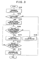
- FIG. 3 is a flowchart showing an example of a control routine executed by the ECU 22 in the battery state of charge determination apparatus 10 according to this embodiment.
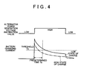
- FIG 4 is a view illustrating temporal variation in the power generation voltage instruction value of the alternator 18 and the charging current of the battery 14 in the battery state of charge determination apparatus 10 according to this embodiment. Note that in FIG 4 , a case in which the battery 14 is in a low state of charge condition and a case in which the battery 14 is in a high state of charge condition are indicated by a thick solid line and a dot-dash line, respectively.
- the ECU 22 calculates the target power generation voltage periodically on the basis of the input data.
- the ECU 22 then causes the alternator 18 to generate power on the basis of the target power generation voltage. More specifically, the ECU 22 switch-drives the voltage adjustment unit such that the target power generation voltage is realized.
- the voltage adjustment unit is switch-driven, an appropriate amount of current flows to the rotor coil, and as a result, the alternator 18 is caused to perform power generation such that the target power generation voltage is realized.
- the charging current of the battery 14 upon the elapse of a predetermined time (10 seconds, for example) after the power generation voltage of the alternator 18 is boosted from a comparatively low first voltage (13.8 volts, for example) to a comparatively high second voltage (14.8 volts, for example) varies in accordance with the state of charge of the battery 14 at that time. More specifically, as shown in FIG. 2 , the charging current of the battery 14 at the elapse point of the predetermined time decreases linearly as the state of charge of the battery 14 increases and increases linearly as the state of charge of the battery 14 decreases.
- the ECU 22 executes processing to increment a counter (to be referred to hereafter as a first counter) that measures time while a vehicle ignition is ON, or in other words while an engine is driven (Step 100). After incrementing the first counter, the ECU 22 determines whether or not the first counter shows a value that equals or exceeds a fixed time (Step 102). The first counter is cleared when the ignition is switched OFF or ON or when the battery 14 is determined to be in the low state of charge condition, as will be described below.
- the fixed time may be a predetermined time set in advance.
- the ECU 22 determines that the fixed time has not elapsed, and therefore terminates the current routine without performing any further processing.
- the ECU 22 determines that the fixed time has elapsed, and therefore performs an adjustment to boost the power generation voltage of the alternator 18 above a normal power generation voltage (Step 104). More specifically, the ECU 22 sets a higher voltage than a normal target power generation voltage calculated on the basis of the input data as a target power generation voltage following boosting of the power generation voltage of the alternator 18 (a boosted target power generation voltage).
- the boosted target power generation voltage may take any value obtained by adding a predetermined voltage to the normal target power generation voltage, for example a value one level higher than the normal target power generation voltage. Further, execution of the processing for boosting the power generation voltage may be permitted only when the normal target power generation voltage calculated on the basis of the input data is smaller than a value which is lower than an upper limit value of the instruction range of the power generation voltages that can be issued to the alternator 18 as instructions by a predetermined voltage.
- the charging current of the battery 14 following boosting of the power generation voltage (the power generation voltage instruction value) is much higher than the charging current of the battery 14 prior to boosting of the generated power.
- the charging current of the battery 14 decreases gradually over time after increasing in response to boosting of the power generation voltage.
- a decrease speed of the charging current at this time differs according to the state of charge of the battery 14. More specifically, the decrease speed of the charging current increases as the state of charge increases and decreases as the state of charge decreases.
- the ECU 22 determines whether or not the charging current of the battery 14 equals or exceeds a predetermined threshold Ta (Step 106).
- the predetermined threshold Ta is a boundary value of the battery charging current used to differentiate the low state of charge condition of the battery 14 from the high state of charge condition of the battery 14, and is set at 35 ampere, for example.
- the low state of charge condition of the battery 14 is a condition in which the state of charge is equal to or smaller than a predetermined state of charge (88%, for example), while the high state of charge condition of the battery 14 is a condition in which the state of charge exceeds the predetermined state of charge.
- Step 106 When determining in Step 106 that the charging current of the battery 14 is smaller than the predetermined threshold Ta, the ECU 22 executes processing to clear a counter (to be referred to hereafter as a second counter) that measures a duration of a high charging current condition in which the charging current of the battery 14 equals or exceeds the predetermined threshold Ta (Step 108).
- a second counter that measures a duration of a high charging current condition in which the charging current of the battery 14 equals or exceeds the predetermined threshold Ta
- Step 110 When determining in Step 106 that the charging current of the battery 14 equals or exceeds the predetermined threshold Ta, on the other hand, the ECU 22 executes processing to increment the second counter (Step 110).
- the ECU 22 determines whether or not the second counter shows a value that equals or exceeds a predetermined time Tb (Step 112).
- the predetermined time Tb is a boundary value of the duration of the high charging current condition, and is set at 10 seconds, for example.
- Step 112 When the second counter shows a smaller value than the predetermined time Tb in Step 112, the ECU 22 determines that the high charging current condition has not been established continuously for the predetermined time Tb, and therefore repeats the processing of Step 106 onward.
- the second counter shows a value that equals or exceeds the predetermined time Tb in Step 112
- the ECU 22 determines that the high charging current condition has been established continuously for the predetermined time Tb, and therefore determines that the battery 14 is in the low state of charge condition (Step 114).
- the battery state of charge determination apparatus 10 when the high charging current condition, in which the charging current of the battery 14 equals or exceeds the predetermined threshold Ta, has not been established continuously for the predetermined time Tb after the power generation voltage of the alternator 18 is boosted above the normal value, the battery 14 is not determined to be in the low state of charge condition, but when the high charging current condition has been established continuously for the predetermined time Tb, the battery 14 is determined to be in the low state of charge condition.
- the charging current of the battery 14 following boosting of the power generation voltage of the alternator 18 is much higher than the charging current of the battery 14 prior to boosting. Further, the charging current of the battery 14 decreases gradually over time after increasing, while the decrease speed of the charging current increases as the state of charge of the battery 14 increases and decreases as the state of charge of the battery 14 decreases.
- the battery state of charge determination apparatus 10 it is possible to determine accurately whether or not the battery 14 is in the low state of charge condition, and therefore erroneous determination of the battery state of charge (for example, a situation in which the battery 14 is determined to be in the high state of charge condition despite actually being in the low state of charge condition, or the like) can be reduced.
- the power generation voltage of the alternator 18 is boosted from the normal value at fixed time intervals while the engine is driven.
- the battery state of charge can be determined at fixed time intervals while the engine is driven, and it is therefore possible to determine that the battery 14 is in the low state of charge condition quickly even during engine driving.
- Step 104 in the routine shown in FIG 3 which is executed by the ECU 22, functions as power generation voltage boosting means, the processing of Step 112 functions as condition determining means, and the processing of Step 114 functions as low state of charge condition determining means.
- the state of charge condition of the battery 14 is determined to belong to either the low state of charge condition or the high state of charge condition, i.e. in binary terms, on the basis of whether or not the condition in which the charging current of the battery 14 equals or exceeds the predetermined threshold Ta has been established continuously for the predetermined time Tb.
- the state of charge condition of the battery 14 may be determined to belong to one of three or more state of charge conditions on the basis of the relationship between the charging current of the battery 14 and the duration.
Landscapes
- Physics & Mathematics (AREA)
- General Physics & Mathematics (AREA)
- Engineering & Computer Science (AREA)
- Power Engineering (AREA)
- Charge And Discharge Circuits For Batteries Or The Like (AREA)
- Control Of Charge By Means Of Generators (AREA)
- Secondary Cells (AREA)
Abstract
Description
- The invention relates to a battery state of charge determination method and a battery state of charge determination apparatus for determining that a battery is in a low state of charge condition in which a state of charge of the battery is equal to or smaller than a predetermined state of charge.
- A method and apparatus for determining a state of charge of a battery is available in the related art (see Japanese Patent Application Publication No.
2010-271288 JP-2010-271288 A - During driving of the engine, however, a precision of the estimated open circuit voltage of the battery at the point where the battery charging/discharging current reaches zero is lower than that of a normal open circuit voltage. Therefore, the relationship between the estimated open circuit voltage and the state of charge varies greatly in accordance with travel conditions of the vehicle, a charging/discharging history and a temperature of the battery, and so on. Hence, with the method described in
JP-2010-271288 A - The invention provides a battery state of charge determination method and a battery state of charge determination apparatus with which erroneous determination of a battery state of charge can be reduced.
- A first aspect of the invention is a battery state of charge determination method including: boosting a power generation voltage of an alternator capable of supplying a charging current to a battery; determining whether or not a condition in which the charging current supplied to the battery equals or exceeds a predetermined threshold has been established continuously for a predetermined time after the power generation voltage of the alternator is boosted; and determining that the battery is in a low state of charge condition, in which a state of charge of the battery is equal to or smaller than a predetermined state of charge, when it is determined that the condition in which the charging current supplied to the battery equals or exceeds the predetermined threshold has been established continuously for the predetermined time.
- A second aspect of the invention is a battery state of charge determination apparatus including: power generation voltage boosting means for boosting a power generation voltage of an alternator capable of supplying a charging current to a battery; condition determining means for determining whether or not a condition in which the charging current supplied to the battery equals or exceeds a predetermined threshold has been established continuously for a predetermined time after the power generation voltage boosting means boosts the power generation voltage of the alternator; and low state of charge condition determining means for determining that the battery is in a low state of charge condition, in which a state of charge of the battery is equal to or smaller than a predetermined state of charge, when the condition determining means determines that the condition in which the charging current supplied to the battery equals or exceeds the predetermined threshold has been established continuously for the predetermined time.
- According to the configurations described above, erroneous determination of the battery state of charge can be reduced.
- Features, advantages, and technical and industrial significance of exemplary embodiments of the invention will be described below with reference to the accompanying drawings, in which like numerals denote like elements, and wherein:
-
FIG 1 is an overall constitutional diagram of a system including a battery state of charge determination apparatus according to an embodiment of the invention; -
FIG 2 shows experiment data expressing a relationship between a battery state of charge and a battery charging current following the elapse of a predetermined time after a power generation voltage of an alternator boosted to a predetermined voltage; -
FIG. 3 is a flowchart showing an example of a control routine executed in the battery state of charge determination apparatus according to the embodiment; and -
FIG. 4 is a view illustrating temporal variation in a power generation voltage instruction value of the alternator and the charging current of the battery in the battery state of charge determination apparatus according to the embodiment. - A specific embodiment of the invention will be described below using the drawings.
-
FIG. 1 is an overall view of asystem 12 including a battery state ofcharge determination apparatus 10 serving as an embodiment of the invention. As shown inFIG 1 , thesystem 12 according to this embodiment includes abattery 14, a vehicleelectric load 16, and analternator 18. Thesystem 12 is an in-vehicle system capable of driving the vehicleelectric load 16 by supplying charged power from thebattery 14 and generated power from thealternator 18, and charging thebattery 14 by supplying generated power from thealternator 18. Further, the battery state ofcharge determination apparatus 10 is an apparatus that determines a state of charge (SOC) of thebattery 14. - The
battery 14, the vehicleelectric load 16, and thealternator 18 are connected to each other via apower line 20. Thebattery 14 is a direct current power supply that outputs a voltage of approximately 12 volts, for example. The vehicleelectric load 16 is a load driven by a supply of power from thebattery 14 and thealternator 18, for example a meter or a lamp. Thealternator 18 is driven using an in-vehicle engine as a power supply to convert rotational energy into electric energy, whereupon thealternator 18 supplies power to the vehicleelectric load 16 and charges thebattery 14 via thepower line 20. - The
alternator 18 includes a rotor coil, a stator coil, and a rectifying circuit that subjects an output of the stator coil to full-wave rectification. Thealternator 18 is driven to generate power in accordance with a current amount flowing to the rotor coil. Alternating current power obtained by power generation in thealternator 18 is rectified by the rectifying circuit so as to be converted into direct current power, whereupon the direct current power is output. Thealternator 18 includes a voltage adjustment unit constituted by a switch element (a MOSFET or the like, for example) or the like that is controlled in order to adjust an output power generation voltage. A voltage applied to the rotor coil of thealternator 18 is adjusted by appropriately switch-driving the voltage adjustment unit. Accordingly, an excitation current flowing to the rotor coil is adjusted, whereby the output power generation voltage is adjusted. - An electronic control unit (to be referred to hereafter as an ECU) 22 having a microcomputer as a main component is connected to the
alternator 18. Data required to calculate a target power generation voltage to be issued to thealternator 18 as an instruction are input into theECU 22 from various external sensors. The data input from the external sensors include conditions of thebattery 14, an operating condition of the vehicleelectric load 16, vehicle traveling conditions, and so on. The conditions of thebattery 14 include at least a voltage across the terminals and a charging/discharging current of thebattery 14, and may further include a battery temperature and so on. The vehicle traveling conditions include the engine operating condition and the accelerator ON/OFF condition, for example. The target power generation voltage is a voltage corresponding to an amount of power to be supplied to at least one of the vehicleelectric load 16 and thebattery 14 from thealternator 18. - The
ECU 22 calculates a target power generation voltage (a power generation voltage instruction value) periodically on the basis of the input data. Target power generation voltages that can be issued to thealternator 18 as instructions may be limited to a predetermined instruction range (a range of 13.8 volts to 14.8 volts, for example), and the value set as the target power generation voltage may be selected from a plurality of values determined in advance as values within the predetermined instruction range. The ECU 22 performs power generation control on thealternator 18 on the basis of the target power generation voltage of thealternator 18. More specifically, theECU 22 switch-drives the voltage adjustment unit of thealternator 18 such that the target power generation voltage is realized. - Next, referring to
FIGS. 2 to 4 , an operation of the battery state ofcharge determination apparatus 10 according to this embodiment will be described.FIG. 2 shows experiment data expressing a relationship between the battery state of charge and a battery charging current following the elapse of a predetermined time after the power generation voltage of thealternator 18 is boosted from a first voltage to a second voltage.FIG. 3 is a flowchart showing an example of a control routine executed by theECU 22 in the battery state ofcharge determination apparatus 10 according to this embodiment.FIG 4 is a view illustrating temporal variation in the power generation voltage instruction value of thealternator 18 and the charging current of thebattery 14 in the battery state ofcharge determination apparatus 10 according to this embodiment. Note that inFIG 4 , a case in which thebattery 14 is in a low state of charge condition and a case in which thebattery 14 is in a high state of charge condition are indicated by a thick solid line and a dot-dash line, respectively. - In this embodiment, as described above, the
ECU 22 calculates the target power generation voltage periodically on the basis of the input data. TheECU 22 then causes thealternator 18 to generate power on the basis of the target power generation voltage. More specifically, theECU 22 switch-drives the voltage adjustment unit such that the target power generation voltage is realized. When the voltage adjustment unit is switch-driven, an appropriate amount of current flows to the rotor coil, and as a result, thealternator 18 is caused to perform power generation such that the target power generation voltage is realized. - Incidentally, assuming that identical data are input into the
ECU 22 on the basis of identical vehicle travel conditions, battery conditions, and so on, the charging current of thebattery 14 upon the elapse of a predetermined time (10 seconds, for example) after the power generation voltage of thealternator 18 is boosted from a comparatively low first voltage (13.8 volts, for example) to a comparatively high second voltage (14.8 volts, for example) varies in accordance with the state of charge of thebattery 14 at that time. More specifically, as shown inFIG. 2 , the charging current of thebattery 14 at the elapse point of the predetermined time decreases linearly as the state of charge of thebattery 14 increases and increases linearly as the state of charge of thebattery 14 decreases. - In this embodiment, first, the
ECU 22 executes processing to increment a counter (to be referred to hereafter as a first counter) that measures time while a vehicle ignition is ON, or in other words while an engine is driven (Step 100). After incrementing the first counter, theECU 22 determines whether or not the first counter shows a value that equals or exceeds a fixed time (Step 102). The first counter is cleared when the ignition is switched OFF or ON or when thebattery 14 is determined to be in the low state of charge condition, as will be described below. The fixed time may be a predetermined time set in advance. - When the first counter shows a value that is smaller than the fixed time, the
ECU 22 determines that the fixed time has not elapsed, and therefore terminates the current routine without performing any further processing. When the first counter shows a value that equals or exceeds the fixed time, on the other hand, theECU 22 determines that the fixed time has elapsed, and therefore performs an adjustment to boost the power generation voltage of thealternator 18 above a normal power generation voltage (Step 104). More specifically, theECU 22 sets a higher voltage than a normal target power generation voltage calculated on the basis of the input data as a target power generation voltage following boosting of the power generation voltage of the alternator 18 (a boosted target power generation voltage). - The boosted target power generation voltage may take any value obtained by adding a predetermined voltage to the normal target power generation voltage, for example a value one level higher than the normal target power generation voltage. Further, execution of the processing for boosting the power generation voltage may be permitted only when the normal target power generation voltage calculated on the basis of the input data is smaller than a value which is lower than an upper limit value of the instruction range of the power generation voltages that can be issued to the
alternator 18 as instructions by a predetermined voltage. - When the power generation voltage of the
alternator 18 is boosted, an ability of thebattery 14 to receive the charging current improves. Therefore, as shown inFIG. 4 , the charging current of thebattery 14 following boosting of the power generation voltage (the power generation voltage instruction value) is much higher than the charging current of thebattery 14 prior to boosting of the generated power. Further, the charging current of thebattery 14 decreases gradually over time after increasing in response to boosting of the power generation voltage. A decrease speed of the charging current at this time differs according to the state of charge of thebattery 14. More specifically, the decrease speed of the charging current increases as the state of charge increases and decreases as the state of charge decreases. - After executing the processing of Step 104, the
ECU 22 determines whether or not the charging current of thebattery 14 equals or exceeds a predetermined threshold Ta (Step 106). The predetermined threshold Ta is a boundary value of the battery charging current used to differentiate the low state of charge condition of thebattery 14 from the high state of charge condition of thebattery 14, and is set at 35 ampere, for example. The low state of charge condition of thebattery 14 is a condition in which the state of charge is equal to or smaller than a predetermined state of charge (88%, for example), while the high state of charge condition of thebattery 14 is a condition in which the state of charge exceeds the predetermined state of charge. - When determining in Step 106 that the charging current of the
battery 14 is smaller than the predetermined threshold Ta, theECU 22 executes processing to clear a counter (to be referred to hereafter as a second counter) that measures a duration of a high charging current condition in which the charging current of thebattery 14 equals or exceeds the predetermined threshold Ta (Step 108). When determining in Step 106 that the charging current of thebattery 14 equals or exceeds the predetermined threshold Ta, on the other hand, theECU 22 executes processing to increment the second counter (Step 110). - After executing the processing of Step 108 or Step 110, the
ECU 22 determines whether or not the second counter shows a value that equals or exceeds a predetermined time Tb (Step 112). The predetermined time Tb is a boundary value of the duration of the high charging current condition, and is set at 10 seconds, for example. - When the second counter shows a smaller value than the predetermined time Tb in Step 112, the
ECU 22 determines that the high charging current condition has not been established continuously for the predetermined time Tb, and therefore repeats the processing of Step 106 onward. When the second counter shows a value that equals or exceeds the predetermined time Tb in Step 112, on the other hand, theECU 22 determines that the high charging current condition has been established continuously for the predetermined time Tb, and therefore determines that thebattery 14 is in the low state of charge condition (Step 114). - Hence, in the battery state of
charge determination apparatus 10 according to this embodiment, when the high charging current condition, in which the charging current of thebattery 14 equals or exceeds the predetermined threshold Ta, has not been established continuously for the predetermined time Tb after the power generation voltage of thealternator 18 is boosted above the normal value, thebattery 14 is not determined to be in the low state of charge condition, but when the high charging current condition has been established continuously for the predetermined time Tb, thebattery 14 is determined to be in the low state of charge condition. - As described above, the charging current of the
battery 14 following boosting of the power generation voltage of thealternator 18 is much higher than the charging current of thebattery 14 prior to boosting. Further, the charging current of thebattery 14 decreases gradually over time after increasing, while the decrease speed of the charging current increases as the state of charge of thebattery 14 increases and decreases as the state of charge of thebattery 14 decreases. Hence, with the battery state ofcharge determination apparatus 10 according to this embodiment, it is possible to determine accurately whether or not thebattery 14 is in the low state of charge condition, and therefore erroneous determination of the battery state of charge (for example, a situation in which thebattery 14 is determined to be in the high state of charge condition despite actually being in the low state of charge condition, or the like) can be reduced. - Furthermore, in this embodiment, the power generation voltage of the
alternator 18 is boosted from the normal value at fixed time intervals while the engine is driven. Hence, with the battery state ofcharge determination apparatus 10 according to this embodiment, the battery state of charge can be determined at fixed time intervals while the engine is driven, and it is therefore possible to determine that thebattery 14 is in the low state of charge condition quickly even during engine driving. - In the above embodiment, the processing of Step 104 in the routine shown in
FIG 3 , which is executed by theECU 22, functions as power generation voltage boosting means, the processing of Step 112 functions as condition determining means, and the processing of Step 114 functions as low state of charge condition determining means. - In the above embodiment, the state of charge condition of the
battery 14 is determined to belong to either the low state of charge condition or the high state of charge condition, i.e. in binary terms, on the basis of whether or not the condition in which the charging current of thebattery 14 equals or exceeds the predetermined threshold Ta has been established continuously for the predetermined time Tb. However, the state of charge condition of thebattery 14 may be determined to belong to one of three or more state of charge conditions on the basis of the relationship between the charging current of thebattery 14 and the duration.
Claims (6)
- A battery state of charge determination method characterized by:boosting a power generation voltage of an alternator (18) capable of supplying a charging current to a battery (14);determining whether or not a condition in which the charging current supplied to the battery (14) equals or exceeds a predetermined threshold has been established continuously for a predetermined time after the power generation voltage of the alternator (18) is boosted; anddetermining that the battery (14) is in a low state of charge condition, in which a state of charge of the battery (14) is equal to or smaller than a predetermined state of charge, when it is determined that the condition in which the charging current supplied to the battery (14) equals or exceeds the predetermined threshold has been established continuously for the predetermined time.
- The battery state of charge determination method according to claim 1, wherein the power generation voltage of the alternator (18) is boosted at fixed time intervals while an engine is driven.
- The battery state of charge determination method according to claim 1 or 2, wherein the power generation voltage of the alternator (18) is boosted to a higher voltage than a target power generation voltage of the alternator (18) calculated on the basis of at least a condition of the battery.
- A battery state of charge determination apparatus characterized by:power generation voltage boosting means (S104) for boosting a power generation voltage of an alternator (18) capable of supplying a charging current to a battery (14);condition determining means (S112) for determining whether or not a condition in which the charging current supplied to the battery (14) equals or exceeds a predetermined threshold has been established continuously for a predetermined time after the power generation voltage boosting means (S104) boosts the power generation voltage of the alternator (18); andlow state of charge condition determining means (S114) for determining that the battery (14) is in a low state of charge condition, in which a state of charge of the battery (14) is equal to or smaller than a predetermined state of charge, when the condition determining means (S112) determines that the condition in which the charging current supplied to the battery (14) equals or exceeds the predetermined threshold has been established continuously for the predetermined time.
- The battery state of charge determination apparatus according to claim 4, wherein the power generation voltage boosting means (S104) boosts the power generation voltage of the alternator (18) at fixed time intervals while an engine is driven.
- The battery state of charge determination apparatus according to claim 4 or 5, wherein the power generation voltage boosting means (S104) boosts the power generation voltage of the alternator (18) to a higher voltage than a target power generation voltage of the alternator (18) calculated on the basis of at least a condition of the battery.
Applications Claiming Priority (1)
| Application Number | Priority Date | Filing Date | Title |
|---|---|---|---|
| JP2012027799A JP5974523B2 (en) | 2012-02-10 | 2012-02-10 | Battery charge rate determination method and battery charge rate determination device |
Publications (3)
| Publication Number | Publication Date |
|---|---|
| EP2626970A2 true EP2626970A2 (en) | 2013-08-14 |
| EP2626970A3 EP2626970A3 (en) | 2018-01-10 |
| EP2626970B1 EP2626970B1 (en) | 2019-07-03 |
Family
ID=47832891
Family Applications (1)
| Application Number | Title | Priority Date | Filing Date |
|---|---|---|---|
| EP13154498.3A Active EP2626970B1 (en) | 2012-02-10 | 2013-02-08 | Battery state of charge determination method and battery state of charge determination apparatus |
Country Status (2)
| Country | Link |
|---|---|
| EP (1) | EP2626970B1 (en) |
| JP (1) | JP5974523B2 (en) |
Cited By (1)
| Publication number | Priority date | Publication date | Assignee | Title |
|---|---|---|---|---|
| CN108988416A (en) * | 2015-05-13 | 2018-12-11 | 广东欧珀移动通信有限公司 | Quick charging method, power adapter and mobile terminal |
Citations (1)
| Publication number | Priority date | Publication date | Assignee | Title |
|---|---|---|---|---|
| JP2010271288A (en) | 2009-05-25 | 2010-12-02 | Mitsubishi Heavy Ind Ltd | Battery charging rate calculation device, battery charging rate calculation method, and program |
Family Cites Families (6)
| Publication number | Priority date | Publication date | Assignee | Title |
|---|---|---|---|---|
| JPH10106631A (en) * | 1996-09-30 | 1998-04-24 | Mitsuoka Denki Seisakusho:Kk | Device for identifying kind of storage means or the like |
| JP3740323B2 (en) * | 1998-07-31 | 2006-02-01 | キヤノン株式会社 | Secondary battery charging method and apparatus |
| JP2005224013A (en) * | 2004-02-05 | 2005-08-18 | Honda Motor Co Ltd | Power supply |
| US7233128B2 (en) * | 2004-07-30 | 2007-06-19 | Ford Global Technologies, Llc | Calculation of state of charge offset using a closed integral method |
| JP2007312469A (en) * | 2006-05-17 | 2007-11-29 | Hitachi Ltd | In-vehicle power supply system, in-vehicle power generator and control device therefor |
| JP5082677B2 (en) * | 2007-08-24 | 2012-11-28 | トヨタ自動車株式会社 | Battery identification method and battery identification device |
-
2012
- 2012-02-10 JP JP2012027799A patent/JP5974523B2/en not_active Expired - Fee Related
-
2013
- 2013-02-08 EP EP13154498.3A patent/EP2626970B1/en active Active
Patent Citations (1)
| Publication number | Priority date | Publication date | Assignee | Title |
|---|---|---|---|---|
| JP2010271288A (en) | 2009-05-25 | 2010-12-02 | Mitsubishi Heavy Ind Ltd | Battery charging rate calculation device, battery charging rate calculation method, and program |
Cited By (1)
| Publication number | Priority date | Publication date | Assignee | Title |
|---|---|---|---|---|
| CN108988416A (en) * | 2015-05-13 | 2018-12-11 | 广东欧珀移动通信有限公司 | Quick charging method, power adapter and mobile terminal |
Also Published As
| Publication number | Publication date |
|---|---|
| JP5974523B2 (en) | 2016-08-23 |
| EP2626970A3 (en) | 2018-01-10 |
| EP2626970B1 (en) | 2019-07-03 |
| JP2013163461A (en) | 2013-08-22 |
Similar Documents
| Publication | Publication Date | Title |
|---|---|---|
| US9300236B2 (en) | Increasing the excitation current of a multiphase AC generator connected to an electrical system of a motor vehicle upon the activation of the generator | |
| JP6414460B2 (en) | Battery deterioration state determination device and deterioration state determination method | |
| US8716966B2 (en) | Rotary electric machine for vehicles | |
| US9871395B2 (en) | Charging control device | |
| JP4158513B2 (en) | Vehicle power generation control device | |
| US20180259584A1 (en) | Lithium ion battery residual capacity estimation device | |
| CN109075730B (en) | Control device for rotating electric machine | |
| US10498154B2 (en) | Electric power system | |
| JP2019030189A (en) | Power system | |
| CN103516275A (en) | Control device and control method for a vehicle AC generator | |
| US20180212457A1 (en) | Method and device for operating an electrical system, and electrical system | |
| CN110361669B (en) | Battery Deterioration Determining Device | |
| EP2289147A1 (en) | Control of battery balance | |
| CN112534702B (en) | Power conversion device | |
| CN107615563A (en) | Device for judging state of battery for auxiliary equipment and method for judging state of battery for auxiliary machinery | |
| EP2626970B1 (en) | Battery state of charge determination method and battery state of charge determination apparatus | |
| JP2004263619A (en) | Power supply control device for vehicles | |
| EP2290388A2 (en) | Battery condition determination | |
| US20080180069A1 (en) | Battery-less power generation control system and straddle type vehicle having the same | |
| JP5541189B2 (en) | Current sensor abnormality determination device | |
| US20130300323A1 (en) | Method and circuit arrangement for charging an intermediate circuit capacitor | |
| US10992162B2 (en) | Method for detecting a state of a vehicle electric system | |
| JP4893434B2 (en) | Vehicle generator control system | |
| JP5285323B2 (en) | Charge control device for secondary battery for vehicle | |
| US9214872B2 (en) | Method for actuating the switching transistors of a rectifier |
Legal Events
| Date | Code | Title | Description |
|---|---|---|---|
| PUAI | Public reference made under article 153(3) epc to a published international application that has entered the european phase |
Free format text: ORIGINAL CODE: 0009012 |
|
| AK | Designated contracting states |
Kind code of ref document: A2 Designated state(s): AL AT BE BG CH CY CZ DE DK EE ES FI FR GB GR HR HU IE IS IT LI LT LU LV MC MK MT NL NO PL PT RO RS SE SI SK SM TR |
|
| AX | Request for extension of the european patent |
Extension state: BA ME |
|
| 17P | Request for examination filed |
Effective date: 20150310 |
|
| RBV | Designated contracting states (corrected) |
Designated state(s): AL AT BE BG CH CY CZ DE DK EE ES FI FR GB GR HR HU IE IS IT LI LT LU LV MC MK MT NL NO PL PT RO RS SE SI SK SM TR |
|
| PUAL | Search report despatched |
Free format text: ORIGINAL CODE: 0009013 |
|
| AK | Designated contracting states |
Kind code of ref document: A3 Designated state(s): AL AT BE BG CH CY CZ DE DK EE ES FI FR GB GR HR HU IE IS IT LI LT LU LV MC MK MT NL NO PL PT RO RS SE SI SK SM TR |
|
| AX | Request for extension of the european patent |
Extension state: BA ME |
|
| RIC1 | Information provided on ipc code assigned before grant |
Ipc: H02J 7/16 20060101AFI20171201BHEP |
|
| GRAP | Despatch of communication of intention to grant a patent |
Free format text: ORIGINAL CODE: EPIDOSNIGR1 |
|
| STAA | Information on the status of an ep patent application or granted ep patent |
Free format text: STATUS: GRANT OF PATENT IS INTENDED |
|
| INTG | Intention to grant announced |
Effective date: 20190215 |
|
| RAP1 | Party data changed (applicant data changed or rights of an application transferred) |
Owner name: TOYOTA JIDOSHA KABUSHIKI KAISHA |
|
| GRAS | Grant fee paid |
Free format text: ORIGINAL CODE: EPIDOSNIGR3 |
|
| GRAA | (expected) grant |
Free format text: ORIGINAL CODE: 0009210 |
|
| STAA | Information on the status of an ep patent application or granted ep patent |
Free format text: STATUS: THE PATENT HAS BEEN GRANTED |
|
| AK | Designated contracting states |
Kind code of ref document: B1 Designated state(s): AL AT BE BG CH CY CZ DE DK EE ES FI FR GB GR HR HU IE IS IT LI LT LU LV MC MK MT NL NO PL PT RO RS SE SI SK SM TR |
|
| REG | Reference to a national code |
Ref country code: GB Ref legal event code: FG4D |
|
| REG | Reference to a national code |
Ref country code: CH Ref legal event code: EP Ref country code: AT Ref legal event code: REF Ref document number: 1152156 Country of ref document: AT Kind code of ref document: T Effective date: 20190715 |
|
| REG | Reference to a national code |
Ref country code: IE Ref legal event code: FG4D |
|
| REG | Reference to a national code |
Ref country code: DE Ref legal event code: R096 Ref document number: 602013057299 Country of ref document: DE |
|
| REG | Reference to a national code |
Ref country code: DE Ref legal event code: R084 Ref document number: 602013057299 Country of ref document: DE |
|
| REG | Reference to a national code |
Ref country code: GB Ref legal event code: 746 Effective date: 20190903 |
|
| REG | Reference to a national code |
Ref country code: NL Ref legal event code: MP Effective date: 20190703 |
|
| REG | Reference to a national code |
Ref country code: LT Ref legal event code: MG4D |
|
| REG | Reference to a national code |
Ref country code: AT Ref legal event code: MK05 Ref document number: 1152156 Country of ref document: AT Kind code of ref document: T Effective date: 20190703 |
|
| PG25 | Lapsed in a contracting state [announced via postgrant information from national office to epo] |
Ref country code: NO Free format text: LAPSE BECAUSE OF FAILURE TO SUBMIT A TRANSLATION OF THE DESCRIPTION OR TO PAY THE FEE WITHIN THE PRESCRIBED TIME-LIMIT Effective date: 20191003 Ref country code: SE Free format text: LAPSE BECAUSE OF FAILURE TO SUBMIT A TRANSLATION OF THE DESCRIPTION OR TO PAY THE FEE WITHIN THE PRESCRIBED TIME-LIMIT Effective date: 20190703 Ref country code: AT Free format text: LAPSE BECAUSE OF FAILURE TO SUBMIT A TRANSLATION OF THE DESCRIPTION OR TO PAY THE FEE WITHIN THE PRESCRIBED TIME-LIMIT Effective date: 20190703 Ref country code: PT Free format text: LAPSE BECAUSE OF FAILURE TO SUBMIT A TRANSLATION OF THE DESCRIPTION OR TO PAY THE FEE WITHIN THE PRESCRIBED TIME-LIMIT Effective date: 20191104 Ref country code: CZ Free format text: LAPSE BECAUSE OF FAILURE TO SUBMIT A TRANSLATION OF THE DESCRIPTION OR TO PAY THE FEE WITHIN THE PRESCRIBED TIME-LIMIT Effective date: 20190703 Ref country code: HR Free format text: LAPSE BECAUSE OF FAILURE TO SUBMIT A TRANSLATION OF THE DESCRIPTION OR TO PAY THE FEE WITHIN THE PRESCRIBED TIME-LIMIT Effective date: 20190703 Ref country code: NL Free format text: LAPSE BECAUSE OF FAILURE TO SUBMIT A TRANSLATION OF THE DESCRIPTION OR TO PAY THE FEE WITHIN THE PRESCRIBED TIME-LIMIT Effective date: 20190703 Ref country code: BG Free format text: LAPSE BECAUSE OF FAILURE TO SUBMIT A TRANSLATION OF THE DESCRIPTION OR TO PAY THE FEE WITHIN THE PRESCRIBED TIME-LIMIT Effective date: 20191003 Ref country code: LT Free format text: LAPSE BECAUSE OF FAILURE TO SUBMIT A TRANSLATION OF THE DESCRIPTION OR TO PAY THE FEE WITHIN THE PRESCRIBED TIME-LIMIT Effective date: 20190703 Ref country code: FI Free format text: LAPSE BECAUSE OF FAILURE TO SUBMIT A TRANSLATION OF THE DESCRIPTION OR TO PAY THE FEE WITHIN THE PRESCRIBED TIME-LIMIT Effective date: 20190703 |
|
| PG25 | Lapsed in a contracting state [announced via postgrant information from national office to epo] |
Ref country code: AL Free format text: LAPSE BECAUSE OF FAILURE TO SUBMIT A TRANSLATION OF THE DESCRIPTION OR TO PAY THE FEE WITHIN THE PRESCRIBED TIME-LIMIT Effective date: 20190703 Ref country code: ES Free format text: LAPSE BECAUSE OF FAILURE TO SUBMIT A TRANSLATION OF THE DESCRIPTION OR TO PAY THE FEE WITHIN THE PRESCRIBED TIME-LIMIT Effective date: 20190703 Ref country code: GR Free format text: LAPSE BECAUSE OF FAILURE TO SUBMIT A TRANSLATION OF THE DESCRIPTION OR TO PAY THE FEE WITHIN THE PRESCRIBED TIME-LIMIT Effective date: 20191004 Ref country code: IS Free format text: LAPSE BECAUSE OF FAILURE TO SUBMIT A TRANSLATION OF THE DESCRIPTION OR TO PAY THE FEE WITHIN THE PRESCRIBED TIME-LIMIT Effective date: 20191103 Ref country code: RS Free format text: LAPSE BECAUSE OF FAILURE TO SUBMIT A TRANSLATION OF THE DESCRIPTION OR TO PAY THE FEE WITHIN THE PRESCRIBED TIME-LIMIT Effective date: 20190703 Ref country code: LV Free format text: LAPSE BECAUSE OF FAILURE TO SUBMIT A TRANSLATION OF THE DESCRIPTION OR TO PAY THE FEE WITHIN THE PRESCRIBED TIME-LIMIT Effective date: 20190703 |
|
| PG25 | Lapsed in a contracting state [announced via postgrant information from national office to epo] |
Ref country code: TR Free format text: LAPSE BECAUSE OF FAILURE TO SUBMIT A TRANSLATION OF THE DESCRIPTION OR TO PAY THE FEE WITHIN THE PRESCRIBED TIME-LIMIT Effective date: 20190703 |
|
| PG25 | Lapsed in a contracting state [announced via postgrant information from national office to epo] |
Ref country code: IT Free format text: LAPSE BECAUSE OF FAILURE TO SUBMIT A TRANSLATION OF THE DESCRIPTION OR TO PAY THE FEE WITHIN THE PRESCRIBED TIME-LIMIT Effective date: 20190703 Ref country code: RO Free format text: LAPSE BECAUSE OF FAILURE TO SUBMIT A TRANSLATION OF THE DESCRIPTION OR TO PAY THE FEE WITHIN THE PRESCRIBED TIME-LIMIT Effective date: 20190703 Ref country code: DK Free format text: LAPSE BECAUSE OF FAILURE TO SUBMIT A TRANSLATION OF THE DESCRIPTION OR TO PAY THE FEE WITHIN THE PRESCRIBED TIME-LIMIT Effective date: 20190703 Ref country code: EE Free format text: LAPSE BECAUSE OF FAILURE TO SUBMIT A TRANSLATION OF THE DESCRIPTION OR TO PAY THE FEE WITHIN THE PRESCRIBED TIME-LIMIT Effective date: 20190703 Ref country code: PL Free format text: LAPSE BECAUSE OF FAILURE TO SUBMIT A TRANSLATION OF THE DESCRIPTION OR TO PAY THE FEE WITHIN THE PRESCRIBED TIME-LIMIT Effective date: 20190703 |
|
| PG25 | Lapsed in a contracting state [announced via postgrant information from national office to epo] |
Ref country code: SK Free format text: LAPSE BECAUSE OF FAILURE TO SUBMIT A TRANSLATION OF THE DESCRIPTION OR TO PAY THE FEE WITHIN THE PRESCRIBED TIME-LIMIT Effective date: 20190703 Ref country code: IS Free format text: LAPSE BECAUSE OF FAILURE TO SUBMIT A TRANSLATION OF THE DESCRIPTION OR TO PAY THE FEE WITHIN THE PRESCRIBED TIME-LIMIT Effective date: 20200224 Ref country code: SM Free format text: LAPSE BECAUSE OF FAILURE TO SUBMIT A TRANSLATION OF THE DESCRIPTION OR TO PAY THE FEE WITHIN THE PRESCRIBED TIME-LIMIT Effective date: 20190703 |
|
| REG | Reference to a national code |
Ref country code: DE Ref legal event code: R097 Ref document number: 602013057299 Country of ref document: DE |
|
| PLBE | No opposition filed within time limit |
Free format text: ORIGINAL CODE: 0009261 |
|
| STAA | Information on the status of an ep patent application or granted ep patent |
Free format text: STATUS: NO OPPOSITION FILED WITHIN TIME LIMIT |
|
| PG2D | Information on lapse in contracting state deleted |
Ref country code: IS |
|
| 26N | No opposition filed |
Effective date: 20200603 |
|
| PG25 | Lapsed in a contracting state [announced via postgrant information from national office to epo] |
Ref country code: SI Free format text: LAPSE BECAUSE OF FAILURE TO SUBMIT A TRANSLATION OF THE DESCRIPTION OR TO PAY THE FEE WITHIN THE PRESCRIBED TIME-LIMIT Effective date: 20190703 |
|
| REG | Reference to a national code |
Ref country code: CH Ref legal event code: PL |
|
| REG | Reference to a national code |
Ref country code: BE Ref legal event code: MM Effective date: 20200229 |
|
| PG25 | Lapsed in a contracting state [announced via postgrant information from national office to epo] |
Ref country code: MC Free format text: LAPSE BECAUSE OF FAILURE TO SUBMIT A TRANSLATION OF THE DESCRIPTION OR TO PAY THE FEE WITHIN THE PRESCRIBED TIME-LIMIT Effective date: 20190703 Ref country code: LU Free format text: LAPSE BECAUSE OF NON-PAYMENT OF DUE FEES Effective date: 20200208 |
|
| PG25 | Lapsed in a contracting state [announced via postgrant information from national office to epo] |
Ref country code: CH Free format text: LAPSE BECAUSE OF NON-PAYMENT OF DUE FEES Effective date: 20200229 Ref country code: LI Free format text: LAPSE BECAUSE OF NON-PAYMENT OF DUE FEES Effective date: 20200229 |
|
| PG25 | Lapsed in a contracting state [announced via postgrant information from national office to epo] |
Ref country code: IE Free format text: LAPSE BECAUSE OF NON-PAYMENT OF DUE FEES Effective date: 20200208 |
|
| PG25 | Lapsed in a contracting state [announced via postgrant information from national office to epo] |
Ref country code: BE Free format text: LAPSE BECAUSE OF NON-PAYMENT OF DUE FEES Effective date: 20200229 |
|
| PGFP | Annual fee paid to national office [announced via postgrant information from national office to epo] |
Ref country code: GB Payment date: 20211230 Year of fee payment: 10 |
|
| PGFP | Annual fee paid to national office [announced via postgrant information from national office to epo] |
Ref country code: DE Payment date: 20211230 Year of fee payment: 10 |
|
| PG25 | Lapsed in a contracting state [announced via postgrant information from national office to epo] |
Ref country code: MT Free format text: LAPSE BECAUSE OF FAILURE TO SUBMIT A TRANSLATION OF THE DESCRIPTION OR TO PAY THE FEE WITHIN THE PRESCRIBED TIME-LIMIT Effective date: 20190703 Ref country code: CY Free format text: LAPSE BECAUSE OF FAILURE TO SUBMIT A TRANSLATION OF THE DESCRIPTION OR TO PAY THE FEE WITHIN THE PRESCRIBED TIME-LIMIT Effective date: 20190703 |
|
| PGFP | Annual fee paid to national office [announced via postgrant information from national office to epo] |
Ref country code: FR Payment date: 20220118 Year of fee payment: 10 |
|
| PG25 | Lapsed in a contracting state [announced via postgrant information from national office to epo] |
Ref country code: MK Free format text: LAPSE BECAUSE OF FAILURE TO SUBMIT A TRANSLATION OF THE DESCRIPTION OR TO PAY THE FEE WITHIN THE PRESCRIBED TIME-LIMIT Effective date: 20190703 |
|
| P01 | Opt-out of the competence of the unified patent court (upc) registered |
Effective date: 20230427 |
|
| REG | Reference to a national code |
Ref country code: DE Ref legal event code: R119 Ref document number: 602013057299 Country of ref document: DE |
|
| GBPC | Gb: european patent ceased through non-payment of renewal fee |
Effective date: 20230208 |
|
| PG25 | Lapsed in a contracting state [announced via postgrant information from national office to epo] |
Ref country code: GB Free format text: LAPSE BECAUSE OF NON-PAYMENT OF DUE FEES Effective date: 20230208 |
|
| PG25 | Lapsed in a contracting state [announced via postgrant information from national office to epo] |
Ref country code: GB Free format text: LAPSE BECAUSE OF NON-PAYMENT OF DUE FEES Effective date: 20230208 Ref country code: FR Free format text: LAPSE BECAUSE OF NON-PAYMENT OF DUE FEES Effective date: 20230228 Ref country code: DE Free format text: LAPSE BECAUSE OF NON-PAYMENT OF DUE FEES Effective date: 20230901 |